
SR Policy and RSVP-TE Tunnel Support
The following lists provide an overview of SR policy and RSVP-TE tunnel supported and unsupported features. Contact your Cisco Crosswork Optimization Engine representative for any capabilities that are not documented in the following lists.
|
Category |
Capability |
Notes |
|---|---|---|
|
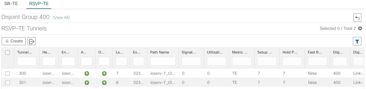
RSVP-TE |
|
— |
|
— |
|
|
FRR protection on tunnels provisioned by Crosswork Optimization Engine |
— |
|
|
Path optimization objective min-metric (IGP,TE, or Latency) |
— |
|
|
Path constraints (affinity and disjointness) |
Only 2 RSVP tunnels per disjoint group or sub-id is supported |
|
|
Binding Label for explicit and dynamic tunnels |
— |
|
|
Signaled Bandwidth |
— |
|
|
Setup/Hold Priority |
— |
|
|
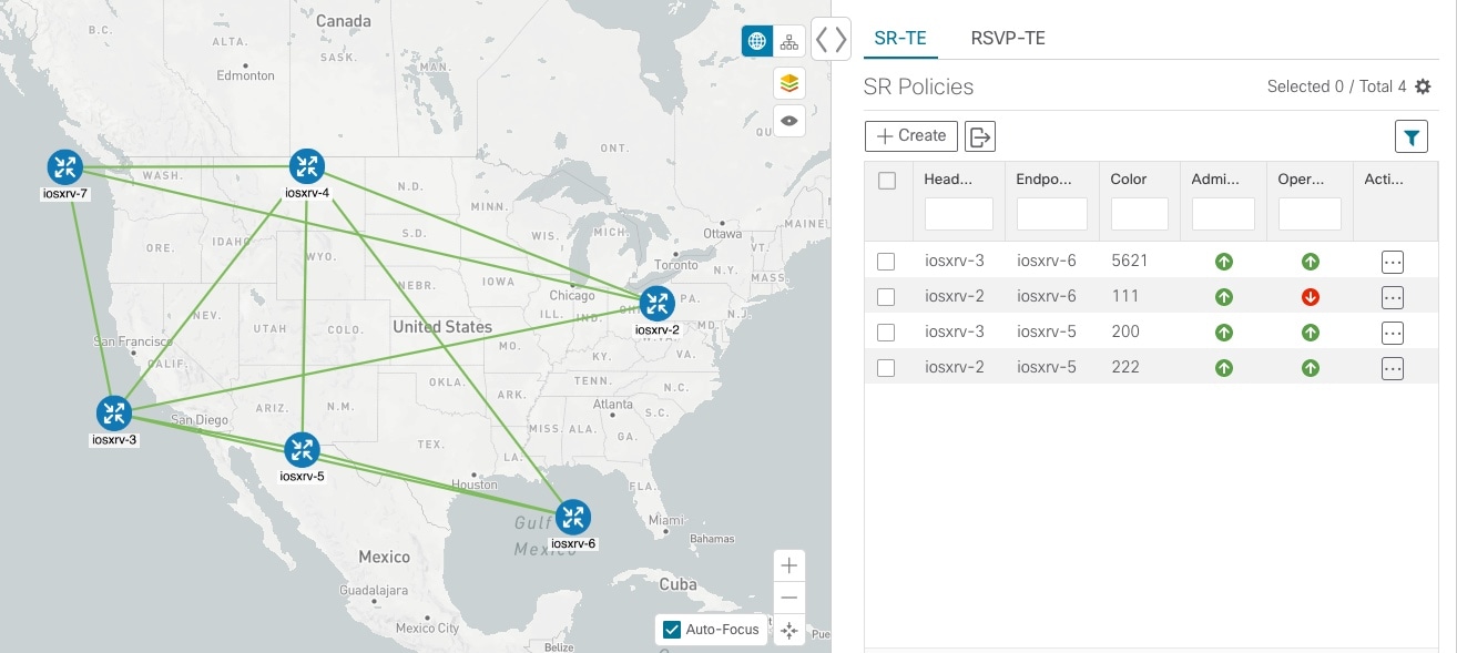
SR Policy |
|
— |
|
Single consistent Segment Routing Global Block (SRGB) configured on routers throughout domain covered by Crosswork Optimization Engine |
If index SIDs are used and there are different SRGB bases along a path of a policy, the label can change along the path. |
|
|
— |
|
|
Protected and Unprotected adjacency SIDs |
— |
|
|
Regular and Strict prefix SIDs |
— |
|
|
SR policy optimization objective min-metric (IGP, TE, and Latency) |
— |
|
|
SR policy path constraints (affinity and disjointness) |
Only 2 SR policies per disjoint group or sub-id are supported |
|
|
Binding SID for explicit or dynamic policies |
— |
|
|
Profile ID |
— |
|
Category |
Description |
Notes |
|---|---|---|
|
RSVP-TE |
Configuring loose hop ERO in COE |
Only strict hops can be configured. If strict hops are not configured for every hop along the path and those hops are not remote interface IPs or loopback IPs, unexpected behavior may occur. For example, a tunnel may remain operationally down, hops may be modified, and so on. |
|
Named tunnels configured on PCCs |
These tunnels are not discovered byCrosswork Optimization Engine. |
|
|
Tunnels with Loopback IPs other than TE router ID for headend or endpoint and path hops |
— |
|
|
Display of active FRR protected paths in the topology map. |
Crosswork Optimization Engine discovers FRR tunnels which are displayed in the topology map, but will not associate an actively protected tunnel with the FRR tunnel being used. The path in the topology map will not include FRR protected paths when protection is active. |
|
|
P2MP tunnels |
— |
|
|
SR Policy |
Provisioning multiple candidate paths via Crosswork Optimization Engine |
These paths are not discovered if configured on PCC. Crosswork Optimization Engine does not support configuration of these paths. |
|
Weighted Equal-Cost Multipath (WECMP) |
— |
|
|
Multiple segment lists per candidate path |
|
|
|
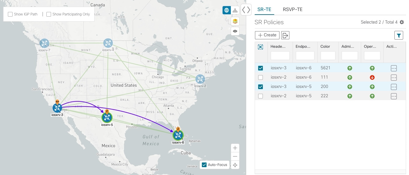
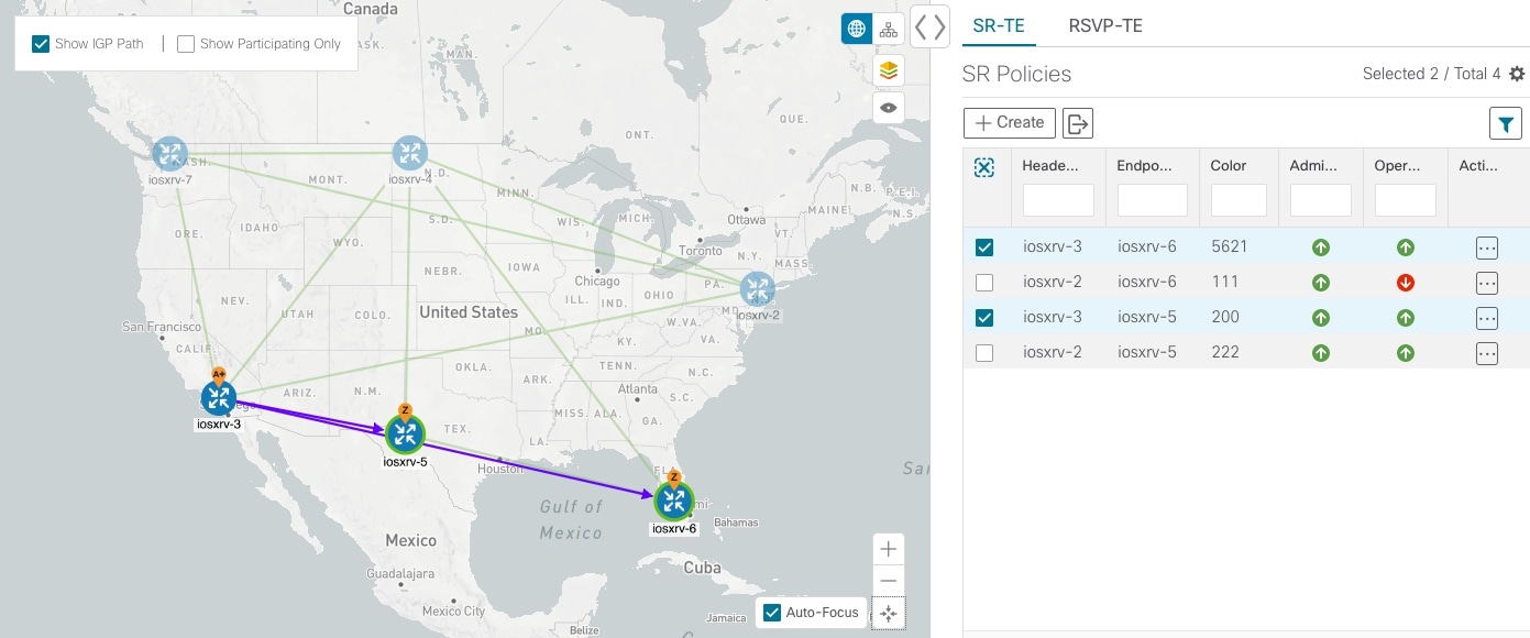
Visualization of multiple candidate paths |
Only the current active path can be seen in the UI. |
|
|
Binding SIDs as Segment List Hops |
— |
|
|
SR IGP Flexible Algorithm (Flex Algo) |
— |
|
|
Anycast SIDs |
— |
|
|
Hop count metric type for policies |
Crosswork Optimization Engine does not support provisioning with this metric type and does not discover this metric type if configured on the PCC |
|
|
Routers that are not SR-capable |
The assumption is that all routers discovered by Crosswork Optimization Engine are SR-capable |
|
|
SR policies with Loopback IPs other than TE router ID for headend/endpoint and prefix SIDs in segment list |
— |
|
|
SR policy provisioned with IPv6 endpoints/hops |
— |
|
|
SRv6 |
Only 2 SR policies per disjoint group/sub-id |
|
|
SR policy optimization objective min-metric with margin |
Not supported for policies provisioned by Crosswork Optimization Engine. Margin is not discovered for PCC-initiated policies. |
|
|
SR policy constraints (resource exclusion or metric bound) |
Not supported for policies provisioned by Crosswork Optimization Engine. Constraints are not discovered for PCC-initiated policies. |
 ) the table or policy details (if in the
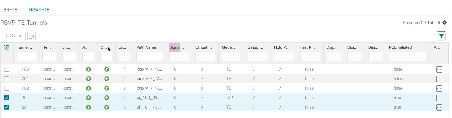

 next to the segment hop you want to move.
 Feedback