-
null
- Understanding SNMP
- SNMPv3 with AES Encryption
- Cisco-Supported MIBs
- About Cisco-Supported MIBs and CISCO-SMI
- Types of MIB Output for SNMP Monitoring
- Types of Cisco-Supported MIBs
- Akamai Connect (CISCO-WAN-OPTIMIZATION-MIB)
- Alarms (CISCO-CONTENT-ENGINE-MIB)
- AOs (CISCO-WAN-OPTIMIZATION-MIB)
- Applications (CISCO-WAN-OPTIMIZATION-MIB)
- AppNav (CISCO-APPNAV-MIB)
- Class Maps (CISCO-WAN-OPTIMIZATION-MIB)
- Configuration (CISCO-CONFIG-MAN-MIB)
- CPU and Memory (CISCO-PROCESS-MIB)
- Devices (CISCO-CDP-MIB and CISCO-ENTITY-ASSET-MIB)
- DRE Cache (CISCO-WAN-OPTIMIZATION-MIB)
- DRE Performance (CISCO-WAN-OPTIMIZATION-MIB)
- HTTP (CISCO-WAN-OPTIMIZATION-MIB)
- Interfaces (IF-MIB)
- IP Routing (IP-MIB, IP-FORWARD-MIB, MIB-II)
- MAPI (CISCO-WAN-OPTIMIZATION-MIB)
- Network Management (EVENT-MIB, HOST-RESOURCES-MIB)
- Policy Maps (CISCO-WAN-OPTIMIZATION-MIB)
- SMB (CISCO-WAN-OPTIMIZATION-MIB)
- SNMP (ENTITY, ISNMP, and SNMP MIB Groups)
- TFO (CISCO-WAN-OPTIMIZATION-MIB)
- Downloading MIB Files
- Using MIBs to Monitor WAAS
- Enabling the SNMP Agent on a WAAS Device
- Checklist for Configuring SNMP
- Preparing for SNMP Monitoring
- Enabling SNMP Traps
- Defining SNMP Triggers to generate User-Defined Traps
- Specifying the SNMP Host
- Specifying the SNMP Community String
- Creating SNMP Views
- Creating an SNMP Group
- Creating an SNMP User
- Configuring SNMP Asset Tag Settings
- Configuring SNMP Contact Settings
- Configuring SNMP Trap Source Settings
Configuring SNMP Monitoring
This chapter describes how to configure Simple Network Management Protocol (SNMP) traps, recipients, community strings, group associations, user security model groups, and user access permissions.

Note![]() Throughout this chapter, the term Cisco WAAS device is used to refer collectively to the WAAS Central Manager and WAEs in your network. The term WAE refers to WAE appliances, and WAE Network Modules (the Cisco Network Modules-WAE family of devices).
Throughout this chapter, the term Cisco WAAS device is used to refer collectively to the WAAS Central Manager and WAEs in your network. The term WAE refers to WAE appliances, and WAE Network Modules (the Cisco Network Modules-WAE family of devices).
This chapter contains the following sections:
- Understanding SNMP
- SNMPv3 with AES Encryption
- Cisco-Supported MIBs
- Checklist for Configuring SNMP
- Preparing for SNMP Monitoring
- Enabling SNMP Traps
- Defining SNMP Triggers to generate User-Defined Traps
- Specifying the SNMP Host
- Specifying the SNMP Community String
- Creating SNMP Views
- Creating an SNMP Group
- Creating an SNMP User
- Configuring SNMP Asset Tag Settings
- Configuring SNMP Contact Settings
- Configuring SNMP Trap Source Settings
Understanding SNMP
SNMP is an interoperable standards-based protocol that allows for external monitoring of Cisco WAAS devices through an SNMP agent.
An SNMP-managed network consists of the following primary components:
- Managed device—A network node that contains an SNMP agent and resides on a managed network. Managed devices include routers, access servers, switches, bridges, hubs, computer hosts, and printers. Each WAAS device running the WAAS software has an SNMP agent.
- SNMP agent—A software module that resides on a managed device. An agent has local knowledge of management information and translates that information into a form that is compatible with SNMP. The SNMP agent gathers data from the MIB, which is the repository for information about device parameters and network data. The agent can also send traps, or notification of certain events, to the management system.
- Management station—Also known as the SNMP host, the management station uses SNMP to send the agent an SNMP Get request to obtain information from the WAAS device. The managed devices then collect and store management information and use SNMP to make this information available to the management station.
Before you can access this SNMP information, you must have deployed an SNMP management application on a management station. This SNMP management station is referred to as the SNMP host because it uses SNMP to send the device agent an SNMP Get request to obtain information from the WAAS device.
This section contains the following topics:
- SNMP Communication Process
- Supported SNMP Versions
- SNMP Security Models and Security Levels
- Downloading MIB Files
- Enabling the SNMP Agent on a WAAS Device
SNMP Communication Process
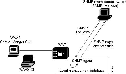
The SNMP management station and the SNMP agent that resides on a WAAS device use SNMP to communicate as follows:
1.![]() The SNMP management station (the SNMP host) uses SNMP to request information from the WAAS device.
The SNMP management station (the SNMP host) uses SNMP to request information from the WAAS device.
2.![]() After receiving these SNMP requests, the SNMP agent on the WAAS device accesses a table that contains information about the individual device. This table, or database, is called a MIB.
After receiving these SNMP requests, the SNMP agent on the WAAS device accesses a table that contains information about the individual device. This table, or database, is called a MIB.
Note![]() The SNMP agent on the WAAS device only initiates communication with the SNMP host under unusual conditions; it will initiate communication when it has a trap it needs to send to the host. For more information on this topic, see Enabling SNMP Traps.
The SNMP agent on the WAAS device only initiates communication with the SNMP host under unusual conditions; it will initiate communication when it has a trap it needs to send to the host. For more information on this topic, see Enabling SNMP Traps.
3.![]() After locating the specified information in the MIB, the agent uses SNMP to send the information to the SNMP management station.
After locating the specified information in the MIB, the agent uses SNMP to send the information to the SNMP management station.
Figure 17-1 illustrates these SNMP operations for an individual WAAS device.
Figure 17-1 SNMP Components in a Cisco WAAS Network
Supported SNMP Versions
The WAAS software supports the following versions of SNMP:
- Version 1 (SNMPv1)—This is the initial implementation of SNMP. See RFC 1157 for a full description of its functionality.
- Version 2 (SNMPv2c)—This is the second release of SNMP, described in RFC 1902. It provides additions to data types, counter size, and protocol operations.
- Version 3 (SNMPv3)—This is the most recent version of SNMP, defined in RFC 2271 through RFC 2275.
Each Cisco device running WAAS software contains the software necessary to communicate information about device configuration and activity using SNMP.
SNMP Security Models and Security Levels
SNMPv1 and SNMPv2c do not have any security (that is, authentication or privacy) features to keep SNMP packet traffic confidential. As a result, packets on the wire can be detected and SNMP community strings compromised.
To solve the security shortcomings of SNMPv1 and SNMPv2c, SNMPv3 provides secure access to WAAS devices by authenticating and encrypting packets over the network. The SNMP agent in the WAAS software supports SNMPv3 as well as SNMPv1 and SNMPv2c.
The following security features are provided in SNMPv3:
- Message integrity—Ensures that nothing has interfered with a packet during transmission.
- Authentication—Determines that the message is from a valid source.
- Encryption—Scrambles the contents of a packet to prevent it from being seen by an unauthorized source.
SNMPv3 provides security models as well as security levels. A security model is an authentication process that is set up for a user and the group in which the user resides. A security level is the permitted level of security within a security model. A combination of a security model and a security level determines which security process is used when an SNMP packet is handled. Three security models are available: SNMPv1, SNMPv2c, and SNMPv3.
Table 17-1 describes the combinations of security models and security levels.
The SNMPv3 agent can be used in the following modes:
- noAuthNoPriv mode (that is, no security mechanisms turned on for packets)
- AuthNoPriv mode (for packets that do not have to be encrypted using the privacy algorithm [DES 56])
- AuthPriv mode (for packets that must be encrypted; privacy requires that authentication be performed on the packet)
Using SNMPv3, users can securely collect management information from their SNMP agents without worrying that the data has been tampered with. Also, confidential information, such as SNMP set packets that change a Content Engine’s configuration, can be encrypted to prevent their contents from being exposed on the wire. Also, the group-based administrative model allows different users to access the same SNMP agent with varying access privileges.
SNMPv3 with AES Encryption
This section contains the following topics:
- About SNMPv3 with AES Encryption
- Operating Guidelines for SNMPv3 with AES Encryption
- Upgrade and Downgrade Guidelines for SNMPv3 with AES Encryption
About SNMPv3 with AES Encryption
SNMP in Cisco WAAS Version 6.4.3d and earlier: Supports only Data Encryption Standard (DES) encryption.
SNMP in Cisco WAAS Version 6.4.3e and later: Supports Advanced Encryption Standard (AES) encryption as well as DES encryption, which provides strong encryption capability for SNMPv3 messages. AES encryption uses the Cipher Feedback (CFB) mode with encryption key sizes of 128, 192, or 256 bits.
The SNMPv3 User-based Security Model (USM) provides three modes of operation:
- noAuthNoPriv: This mode is similar to the SNMPv1 and SNMPv2c model, in that a username is treated in a manner equivalent to the community string. This mode does not utilize strong authentication and does not encrypt SNMP traffic.
- authNoPriv: This mode provides strong authentication via SHA or MD5, but does not encrypt SNMP traffic.
- authPriv: This mode provides strong authentication via SHA or MD5, and encrypts SNMP messages using DES encryption algorithm.
For Cisco WAAS Version 6.4.3e and later, Cisco provides support for AES as an additional option for message encryption under the SNMPv3 authPriv mode.
Command modification for SNMPv3 with AES encryption:
For Cisco WAAS Version 6.4.3e and later, the global configuration command snmp-server user name group contains the parameter protocol AES {128 | 192 |256} | DES. This parameter specifies the encryption method and key length. For more information, see the Cisco Wide Area Application Services Command Reference.
Operating Guidelines for SNMPv3 with AES Encryption
Consider the following operating guidelines for SNMPv3 with AES encryption:
- If one of the devices in a device group is running an earlier version than Cisco WAAS Version 6.4.3e, you must upgrade the device to Cisco WAAS Version 6.4.3e for the device group to create an AES encryption user for the group.
- If Priv Password is Empty, do not select Protocol Algorithm and AES Encryption.
- If Priv Password is entered, select Priv Protocol either (DES or AES).
- If Protocol is selected by AES, select AES Encryption.
- If Protocol is selected by DES, do not select AES Encryption.
- If no-auth is selected, do not select Protocol.
- If Priv Password is Empty, do not select AES Encryption.
- If the Cisco WAAS Central Manager is running Cisco WAAS Version 6.4.3e or later, and the device is part of a device group containing devices running 6.4.3e, then you can create the AES encryption user.
Upgrade and Downgrade Guidelines for SNMPv3 with AES Encryption
Consider the following upgrade and downgrade guidelines for SNMPv3 with AES encryption:
- WAAS 6.4.3d release and lower versions support DES encryption only. The privacy protocol cannot be configured, and is not displayed in the running-configuration and show commands.
- If you downgrade from Cisco WAAS Version 6.4.3e to an earlier version, the downgrade will not proceed if there are SNMPv3 users configured in authpriv mode with Priv Protocol AES. A Warning message will be displayed in the CLI if AES encryption users are present in the running configuration. A pop-up message will also be displayed, if you attempt to downgrade from the WAAS Central Manager and if AES encryption users are present in the running configuration. You must remove the AES encryption users from configuration and downgrade again to complete the image installation.
- After upgrading to Cisco WAAS Version 6.4.3e or later, the existing SNMP users in authpriv mode, if present, will be added with Priv Protocol DES.
Cisco-Supported MIBs
This section contains the following topics:
- About Cisco-Supported MIBs and CISCO-SMI
- Types of MIB Output for SNMP Monitoring
- Types of Cisco-Supported MIBs
- Downloading MIB Files
- Using MIBs to Monitor WAAS
About Cisco-Supported MIBs and CISCO-SMI
A Management Information Base (MIB) is a collection of managed objects, arranged in a hierarchical tree of MIB modules, groups, and objects:
For example, CISCO-WAN-OPTIMIZATION-MIB contains many types of optimization groups, including cwoAoStats and cwoTfoStats.
MIB group—Contains the prefix for a set of related MIB objects, such as cwoAoStats (AO statistics) and cwoTfoStats (TFO statistics).
–![]() The cwoAoStatsIsConfigured MIB object indicates if the AO is configured or not.
The cwoAoStatsIsConfigured MIB object indicates if the AO is configured or not.
–![]() The cwoTfoStatsLoadStatus displays the current TFO load status (such as “operating normally” or “overloaded”).
The cwoTfoStatsLoadStatus displays the current TFO load status (such as “operating normally” or “overloaded”).
The Structure of Management Information (SMI) defines the framework within which you can define or construct a MIB. The CISCO-SMI MIB group describes the structure of Cisco MIBs.
Note![]() SNMP views are broken in software release versions 6.1.1x, 6.2.1x, 6.2.3x, 6.4.1x. When you upgrade from release version 5.x to a release version 6.x.x, we recommend that you upgrade to 6.4.3 as the views are restored in 6.4.3 and later.
SNMP views are broken in software release versions 6.1.1x, 6.2.1x, 6.2.3x, 6.4.1x. When you upgrade from release version 5.x to a release version 6.x.x, we recommend that you upgrade to 6.4.3 as the views are restored in 6.4.3 and later.
Types of MIB Output for SNMP Monitoring
MB Output for Statistical Data
MIB output can provide information about a device, interface, or process at a specified moment in time. Figure 17-2 shows an example of MIB output of statistical data for the MIB object cwoDreCacheStats. This object displays DRE cache information, such as the current operational status, the portion of the disk space allocated for DRE cache, the age of the oldest data unit the data block, and the amount of data units replaced in the last hour.
Figure 17-2 Sample MIB Output for DRE Cache Information with cwoDreCacheStats
MIB Output for Trend Data
The greatest value provided by MIBs may be in enabling SNMP monitoring to use the external MIB tool to gather statistics — and then provide trend data from these statistics, in either text or graphical format. This enables you to more easily identify anomalies in your WAAS network, and therefore to more effectively plan or modify your network.
For example, in the output shown in the above Figure 17-2, the MIB cwoDreCacheStatsUsed provides information on the percentage of DRE disk space currently being used:
If you want to monitor the trend of how DRE disk space is being used over a particular period of time, you could run the cwoDreCacheStatsUsed MIB for a specified time range. As shown below in Figure 17-3, you could view data for a specified time range that displays the usage trend for the DRE cache disk space.
Figure 17-3 Sample MIB Output for Percentage of DRE Disk Space Being Used
For more information on MIB usage with SNMP monitoring, and for more examples of MIB output, see Using MIBs to Monitor WAAS.
Types of Cisco-Supported MIBs
This section describes the types of Cisco-supported MIBs, in alphabetical order by topic:
- Akamai Connect (CISCO-WAN-OPTIMIZATION-MIB)
- Alarms (CISCO-CONTENT-ENGINE-MIB)
- AOs (CISCO-WAN-OPTIMIZATION-MIB)
- Applications (CISCO-WAN-OPTIMIZATION-MIB)
- AppNav (CISCO-APPNAV-MIB)
- Class Maps (CISCO-WAN-OPTIMIZATION-MIB)
- Configuration (CISCO-CONFIG-MAN-MIB)
- CPU and Memory (CISCO-PROCESS-MIB)
- Devices (CISCO-CDP-MIB and CISCO-ENTITY-ASSET-MIB)
- DRE Cache (CISCO-WAN-OPTIMIZATION-MIB)
- DRE Performance (CISCO-WAN-OPTIMIZATION-MIB)
- HTTP (CISCO-WAN-OPTIMIZATION-MIB)
- Interfaces (IF-MIB)
- IP Routing (IP-MIB, IP-FORWARD-MIB, MIB-II)
- MAPI (CISCO-WAN-OPTIMIZATION-MIB)
- Network Management (EVENT-MIB, HOST-RESOURCES-MIB)
- Policy Maps (CISCO-WAN-OPTIMIZATION-MIB)
- SMB (CISCO-WAN-OPTIMIZATION-MIB)
- SNMP (ENTITY, ISNMP, and SNMP MIB Groups)
- TFO (CISCO-WAN-OPTIMIZATION-MIB)
Akamai Connect (CISCO-WAN-OPTIMIZATION-MIB)
Table 17-2 shows the Akamai Connect MIB objects associated with the cwoAoHttpxStatsAKC MIB object, for a specified caching mode: Standard, Basic, Bypass, or Advanced. For each Akamai Connect caching mode, there are MIB objects that provide the following types of information:
- Cache transactions—The Akamai Connect cache statistics for the total number of cache-hit transactions that were served from cache in the specified caching mode.
- Cache transactions percent—The percentage of total number of cache-hit HTTP transactions in the specified caching mode.
- Cache response time saved—The total response time saved for cache-hit HTTP transactions in the specified Akamai Connect cache mode, in milliseconds.
- Average cache response time saved—The average response time saved per cache-hit HTTP transaction in the specified Akamai Connect cache mode, in milliseconds.
- Response in bytes—The total number of response bytes saved for cache-hit HTTP transactions in the specified Akamai Connect cache mode.
- Response bytes percent—The percentage of total number of response bytes saved for cache-hit HTTP transactions in the specified Akamai Connect cache mode.
- Response time saved percent—The percentage of total response time saved for cache-hit HTTP transactions in the specified Akamai Connect cache mode.
Table 17-2 Akamai Connect MIB Objects
Alarms (CISCO-CONTENT-ENGINE-MIB)
Table 17-3 describes CISCO-CONTENT-ENGINE-MIB objects that are used to verify if there are critical, major, or minor alarms raised on the system.
AOs (CISCO-WAN-OPTIMIZATION-MIB)
The CISCO-WAN-OPTIMIZATION-MIB group displays information about the status and statistics associated with application optimizers.
The Application Optimizers (AOs), also known as Application Acclerators, statistics MIB group displays status information such as configuration or license information for AOs including HTTP, SSL, MAPI, SMB, and ICA.
This section contains the following tables for the cwoAoStats MIB objects:
- Table 17-4, “AO Name, Configuration, and License MIB Objects”
- Table 17-5, “AO Operational Status, Startup Time, and Reset Time MIB Objects”
- Table 17-6, “AO Summary Connection Information MIB Objects”
- Table 17-7, “AO Current Connection Information MIB Objects”
- Table 17-8, “AO Load Status and Bandwidth Information MIB Objects”
Table 17-4 AO Name, Configuration, and License MIB Objects
Table 17-5 AO Operational Status, Startup Time, and Reset Time MIB Objects
cwoAoStats MIB Objects for AO Summary Connection Information
Table 17-6 AO Summary Connection Information MIB Objects
Table 17-7 AO Current Connection Information MIB Objects
Table 17-8 AO Load Status and Bandwidth Information MIB Objects
|
|
|
|---|---|
The percentage bandwidth optimization achieved due to optimization done by the AO. |
Applications (CISCO-WAN-OPTIMIZATION-MIB)
The cwoAppStats MIB object displays information about application optimization and traffic.
Table 17-9 Applications Information MIB Objects
AppNav (CISCO-APPNAV-MIB)
The CISCO-APPNAV-MIB group displays information about AppNavwhen the WAAS device is in AppNav Controller mode.
AppNav Controller MIB Objects
An AppNav Controller is a device that intercepts network traffic and, based on a flow policy, distributes that traffic to one more WAAS nodes for optimization. Table 17-10 displays AppNav Controller MIB objects.
Table 17-10 AppNav Controller Group MIB Objects
AppNav Controller Group MIB Objects
An AppNav Controller Group is a group of AppNav Controllers that together provide the necessary intelligence for handling asymmetric flows and high availability. Table 17-11 displays AppNav Controller Group MIB objects.
Table 17-11 AppNav Controller Group MIB Objects
AppNav Service Node MIB Objects
A WAAS node is also known as a service node. Table 17-12 displays AppNav service node MIB objects.
Table 17-12 AppNav Service Node MIB Objects
AppNav Service Node Group MIB Objects
A WAAS node is also known as a service node. Table 17-13 displays AppNav service node MIB objects.
Table 17-13 AppNav Service Node MIB Objects
AppNav Service Node Group MIB Objects
A Service Node Group is also known as a WAAS Node Group. Table 17-14 displays AppNav Service Node Group MIB objects.
Table 17-14 AppNav Service Node Group Information MIB Objects
AppNav Service Context MIB Objects
A service context is used to tie the AppNav Controller group, service node group, and AppNav policy map together. Table 17-15 displays the AppNav Service Context MIB objects.
Table 17-15 AppNav Service Context Information MIB Objects
Class Maps (CISCO-WAN-OPTIMIZATION-MIB)
AppNav class maps classify traffic according to one or more match conditions, such as peer device ID, or a mix of one peer device ID and the source IP, or destination IP, or destination port. Table 17-16 shows class map information MIB objects.
Table 17-16 Class Map Information MIB Objects
Configuration (CISCO-CONFIG-MAN-MIB)
The CISCO-CONFIG-MAN-MIB group represents a model of configuration data that exists in various locations:
- Running—In use by the running system
- Terminal—Saved to whatever hardware is attached as the terminal
- Local—Saved locally in NVRAM or in flash memory
- Remote—Saved to a server on the network
Note![]() The CISCO-CONFIG-MAN-MIB group includes only operations that are specifically related to configuration, although some of the system functions can be used for general file storage and transfer.
The CISCO-CONFIG-MAN-MIB group includes only operations that are specifically related to configuration, although some of the system functions can be used for general file storage and transfer.
CPU and Memory (CISCO-PROCESS-MIB)
The CISCO-PROCESS-MIB group displays memory and CPU usage on the device and also describes active system processes.
CPU utilization presents a status of how busy the system is. The numbers are a ratio of the current idle time over the longest idle time. (This information should be used as an estimate only.)
Table 17-17 CPU and Memory Information MIB Objects
|
|
|
|---|---|
The overall CPU percentage showing how busy the system was in the last 1 minute. |
|
The overall CPU percentage showing how busy the system was in the last 5 minutes. |
Devices (CISCO-CDP-MIB and CISCO-ENTITY-ASSET-MIB)
CISCO-CDP-MIB Group
The CISC-CDP-MIB group displays the ifIndex value of the local interface.
- For 802.3 repeaters on which the repeater ports do not have ifIndex values assigned, this value is a unique value for the port and is greater than any ifIndex value supported by the repeater.
- In this example, the specific port is indicated by the corresponding values of cdpInterfaceGroup and cdpInterfacePort, where these values correspond to the group number and the port number values of RFC 1516.
CISCO-ENTITY-ASSET-MIB Group
The CISCO-ENTITY-ASSET-MIB group provides information about items in the entPhysicalTable MIB object, including part number, serial number, hardware version, firmware ID and software ID. A full description of these is provided in RFC 2037.
Note the following about information listed in entPhysicalTable:
- Displayed information includes the orderable part number, serial number, hardware revision, manufacturing assembly number and revision, firmware ID and revision (if any), and software ID and revision (if any) of relevant entities listed in entPhysicalTable. Entities that have none of this data available are not listed in this MIB.
- The entPhysicalTable is sparsely populated. Therefore, some variables may not exist for a particular entity at a particular time.
For example, a row that represents a powered-off module may have no values for software ID (ceAssetSoftwareID) and revision (ceAssetSoftwareRevision). Similarly, a power supply would probably never have firmware or software information listed in the table.
For example, a manufacturing date in the serial number, consider all data items to be a single unit. Do not decompose the items or parse them. Use only string equal and unequal operations on them.
DRE Cache (CISCO-WAN-OPTIMIZATION-MIB)
Table 17-18 displays optimization DRE cache statistics MIB objects, which provide information such as the portion of disk space allocated for DRE cache or the percentage of DRE disk space currently being used.
Table 17-18 DRE Cache Statistics MIB Objects
DRE Performance (CISCO-WAN-OPTIMIZATION-MIB)
Table 17-19 displays DRE performance MIB objects, which provide information such as DRE compression ratio during decoding or the decoding average message size.
Table 17-19 DRE Performance Statistics MIB Objects
|
|
|
|---|---|
The Encoding average latency introduced to compress a message. |
|
The Decoding average latency introduced to compress a message. |
|
HTTP (CISCO-WAN-OPTIMIZATION-MIB)
Table 17-20 shows the HTTP AO information MIB objects, which provide information such as the percentage estimated time saved due to optimizations done by HTTP AO since it was started or the total number of SharePoint Optimized HTTP sessions.
Table 17-20 HTTP AO Information MIB Objects
Note![]() Discontinuities in the value of these HTTP counters can occur at re-initialization of the HTTP AO. The last discontinuity time is indicated by the value of cwoAoStatsLastResetTime for the HTTP AO.
Discontinuities in the value of these HTTP counters can occur at re-initialization of the HTTP AO. The last discontinuity time is indicated by the value of cwoAoStatsLastResetTime for the HTTP AO.
Interfaces (IF-MIB)
The IF-MIB group supports querying for interface-related statistics including 64-bit interface counters. These counters include received and sent octets, unicast, multicast, and broadcast packets on the device interfaces. All the objects from ifXEntry are supported except for ifCounterDiscontinuityTime. This MIB is documented in RFC 2233.
Loopback interface interface information are not reported.
A transmission error or discard can point to Layer 1 or Layer 2 problems, such as a bad cable or a speed/duplex mismatch on a connected switch or router.
This section contains the following types of MIB objects for the IF-MIB group:
Interface Description MIB Object
The ifDescr MIB object displays information about the interface, including the name of the manufacturer, the product name, and the version of the hardware or software interface.
Interface Status MIB Objects
This section describes two interface status MIB objects:
–![]() up (1)—The interface is up and ready to transmit and receive network traffic.
up (1)—The interface is up and ready to transmit and receive network traffic.
–![]() down (2)—The interface is down.
down (2)—The interface is down.
–![]() testing (3)—In the Testing state, no operational packets can be passed.
testing (3)—In the Testing state, no operational packets can be passed.
Note![]() At system startup, all interfaces start with ifAdminStatus down. After either management action or configuration information, ifAdminStatus is changed to either up or testing, or remains down.
At system startup, all interfaces start with ifAdminStatus down. After either management action or configuration information, ifAdminStatus is changed to either up or testing, or remains down.
–![]() up (1)—The interface is up and ready to transmit and receive network traffic.
up (1)—The interface is up and ready to transmit and receive network traffic.
–![]() down (2)—The interface is down.
down (2)—The interface is down.
–![]() testing(3)—In the Testing state, no operational packets can be passed.
testing(3)—In the Testing state, no operational packets can be passed.
–![]() unknown(4)—The status of the interface cannot be determined.
unknown(4)—The status of the interface cannot be determined.
–![]() dormant(5)—The interface is waiting for an external action.
dormant(5)—The interface is waiting for an external action.
–![]() notPresent(6)—The interface has a missing component; usually a missing hardware component.
notPresent(6)—The interface has a missing component; usually a missing hardware component.
–![]() lowerLayerDown(7)—The interface is down due to a lower-layer interface.
lowerLayerDown(7)—The interface is down due to a lower-layer interface.
Note![]() If ifAdminStatus is down, then ifOperStatus should also be down. If ifAdminStatus is up, then ifOperStatus should also be up.
If ifAdminStatus is down, then ifOperStatus should also be down. If ifAdminStatus is up, then ifOperStatus should also be up.
Interface Discards MIB Objects
Table 17-21 Interface Discards MIB Objects
Note![]() Discontinuities in the value of ifInDiscards or of ifOutDiscards can occur at re-initialization of the management system and at other times, as indicated by the value ifCounterDiscontinuityTime.
Discontinuities in the value of ifInDiscards or of ifOutDiscards can occur at re-initialization of the management system and at other times, as indicated by the value ifCounterDiscontinuityTime.
Interface Errors MIB Objects
Table 17-22 Interface Errors MIB Objects
Note![]() Discontinuities in the value of ifInErrors or of ifOutErrors can occur at re-initialization of the management system and at other times, as indicated by the value ifCounterDiscontinuityTime.
Discontinuities in the value of ifInErrors or of ifOutErrors can occur at re-initialization of the management system and at other times, as indicated by the value ifCounterDiscontinuityTime.
IP Routing (IP-MIB, IP-FORWARD-MIB, MIB-II)
IP-MIB Group
The IP-MIB group manages IP and ICMP implementations, excluding their management of IP routes.
IP-FORWARD-MIB Group
Displays Classless Inter-Domain Routing (CIDR) multi-path IP Routes.
MIB-II Group
The MIB-II group is the Internet Standard MIB, and is used with network management protocols in TCP/IP-based internets. The MIB-II is documented in RFC 1213, and is found in the RFC1213-MIB file in the v1 directory on the download site (other MIBs are in the v2 directory).
Note![]() The following objects from this MIB are not supported:
The following objects from this MIB are not supported:
—ifInUnknownProtos
—ifOutNUcastPkts
—ipRouteAge
—TcpConnEntry group
—egpInMsgs
—egpInErrors
—egpOutMsgs
—egpOutErrors
—EgpNeighEntry group
—egpAs
—atTable
—ipRouteTable
MAPI (CISCO-WAN-OPTIMIZATION-MIB)
Table 17-23 displays the Message Application Programming Interface (MAPI) AO MIB objects.
Note![]() For these MIB objects, discontinuities in the value of the counter can occur at re-initialization of the MAPI AO. The last discontinuity time is indicated by the value of cwoAoStatsLastResetTime for the MAPI AO.
For these MIB objects, discontinuities in the value of the counter can occur at re-initialization of the MAPI AO. The last discontinuity time is indicated by the value of cwoAoStatsLastResetTime for the MAPI AO.
Table 17-23 MAPI AO MIB Objects
Network Management (EVENT-MIB, HOST-RESOURCES-MIB)
EVENT-MIB Group
The EVENT-MIB group defines the event triggers and actions for network management purposes. This MIB is described in RFC 2981.
HOST-RESOURCES-MIB Group
This MIB manages host systems. The term “host” implies any computer that communicates with other similar computers connected to the Internet.
The HOST-RESOURCES-MIB provides attributes that are common to all Internet hosts, for example, personal computers and systems that run variants of UNIX. It does not apply to devices whose primary function is communications services (terminal servers, routers, bridges, monitoring equipment).
Note![]() The following objects from this MIB are not supported:
The following objects from this MIB are not supported:
—HrPrinterEntry
—hrSWOSIndex
—hrSWInstalledGroup
Policy Maps (CISCO-WAN-OPTIMIZATION-MIB)
Policy maps associate policy actions with class maps. Table 17-24 shows the policy maps MIB objects, which display information such as the type of policy map or the total number of connections processed by the policy map since it has been active.
Table 17-24 Policy Maps MIB Objects
SMB (CISCO-WAN-OPTIMIZATION-MIB)
The CISCO-WAN-OPTIMIZATION-MIB group displays information about the status and statistics associated with optimization and application accelerators.
Note![]() For these MIB objects, discontinuities in the value of the counter can occur at re-initialization of the SMB AO. The last discontinuity time is indicated by the value of cwoAoStatsLastResetTime for the SMB AO.
For these MIB objects, discontinuities in the value of the counter can occur at re-initialization of the SMB AO. The last discontinuity time is indicated by the value of cwoAoStatsLastResetTime for the SMB AO.
This section describes the cwoAoSmbxStats MIB objects, and contains the following topics:
- About SMB Statistics MIB Objects
- cwoAoSmbxStats MIB Objects for Cache Information
- cwoAoSmbxStats MIB Objects for Client and Server Information
- cwoAoSmbxStats MIB Objects for LAN and WAN Information
- cwoAoSmbxStats MIB Objects for RTT, Response Time, and File Information
- cwoAoSmbxStats MIB Objects for SMB Requests Information
About SMB Statistics MIB Objects
The Server Message Block (SMB) application accelerator (AO) transparently accelerates traffic and supports prepositioning of files. It relies on automatic discovery. You can fine-tune this accelerator for specific traffic needs.
cwoAoSmbxStats MIB Objects for Cache Information
Table 17-25 SMB AO Cache MIB Objects
cwoAoSmbxStats MIB Objects for Client and Server Information
Table 17-26 SMB AO Client and Server MIB Objects
cwoAoSmbxStats MIB Objects for LAN and WAN Information
Table 17-27 SMB AO LAN and WAN MIB Objects
cwoAoSmbxStats MIB Objects for RTT, Response Time, and File Information
Table 17-28 SMB RTT, Response Time, and File Information MIB Objects
|
|
|
|---|---|
The total round trip time (RTT) for all SMB connections since it was started. |
|
The total response time saved due to SMB AO optimizations since it was started. |
|
cwoAoSmbxStats MIB Objects for SMB Requests Information
Table 17-29 SMB Requests MIB Objects
SNMP (ENTITY, ISNMP, and SNMP MIB Groups)
This section describes the following SNMP MIB groups:
- ENTITY-MIB—Represents multiple logical entities supported by a single SNMP agent. This MIB is documented in RFC 2737. The following objects are supported:
- SNMP-FRAMEWORK-MIB—Facilitates remote configuration and administration of the SNMP entity. This MIB is documented in RFC 2571.
- SNMP-NOTIFICATION-MIB—Contains objects for the remote configuration of the parameters used by an SNMP entity for the generation of notifications. This MIB is documented in RFC 3413.
- SNMP-TARGET-MIB—Provides information about specifying targets of management operations for notification filtering and for proxy forwarding. This MIB is documented in RFC 3413.
- SNMP-USM-MIB—Provides information on the User-based Security Model.
- SNMP-VACM-MIB—Provides information on the View-based Access Control Model.
- SNMPv2-MIB—For this MIB group, WAAS supports the following MIB objects:
–![]() coldStart—Signifies that the SNMPv2 entity, acting in an agent role, is reinitializing itself and that its configuration may have been altered.
coldStart—Signifies that the SNMPv2 entity, acting in an agent role, is reinitializing itself and that its configuration may have been altered.
–![]() linkUp—The link up trap/notification.
linkUp—The link up trap/notification.
–![]() linkDown—The link down trap/notification.
linkDown—The link down trap/notification.
–![]() authenticationFailure—Signifies that the SNMPv2 entity, acting in an agent role, has received a protocol message that is not properly authenticated. While all implementations of the SNMPv2 must be capable of generating this trap, the snmpEnableAuthenTraps object indicates whether this trap will be generated.
authenticationFailure—Signifies that the SNMPv2 entity, acting in an agent role, has received a protocol message that is not properly authenticated. While all implementations of the SNMPv2 must be capable of generating this trap, the snmpEnableAuthenTraps object indicates whether this trap will be generated.
TFO (CISCO-WAN-OPTIMIZATION-MIB)
The CISCO-WAN-OPTIMIZATION-MIB group displays information about the status and statistics associated with optimization and application accelerators.
This section describes the cwoTfoStats MIB objects, and contains the following topics:
About TFO Statistics MIB Objects
WAAS uses a variety Transport Flow Optimization (TFO) features to optimize TCP traffic intercepted by the WAAS devices. TFO protects communicating clients and servers from negative WAN conditions, such as bandwidth constraints, packet loss, congestion, and retransmission.
cwoTfoStats MIB Object for TFO Load Status
Table 17-30 TFO Load Status MIB Object
cwoTfoStats MIB Objects for TFO Summary Connection Information
Table 17-31 TFO Summary Connection MIB Objects
cwoTfoStats MIB Objects for TFO Current Connection Information
Table 17-32 TFO Current Connection MIB Objects
Downloading MIB Files
You can download the MIB files for most of the MIBS that are supported by a device that is running the WAAS software from the following Cisco FTP site:
ftp://ftp.cisco.com/pub/mibs/v2
You can download the RFC1213-MIB file (for MIB-II) from the following Cisco FTP site:
ftp://ftp.cisco.com/pub/mibs/v1
The MIB objects that are defined in each MIB are described in the MIB files at the above FTP sites and are self-explanatory.
Using MIBs to Monitor WAAS
This section contains usage examples and sample output for using MIB files to monitor WAAS:
Using MIBs to Display Alarm Status
This section provides usage examples and sample output for WAAS alarm information. For more information on these MIBs, see Alarms (CISCO-CONTENT-ENGINE-MIB).
Using MIBs to Display AO Information and Status
This section provides usage examples and sample MIB output for WAAS AO information and status. For more information on these MIBs, see AOs (CISCO-WAN-OPTIMIZATION-MIB).
Using MIBs to Display DRE Cache and Performance Information
This section provides usage examples and sample MIB output for DRE cache and performance information.
For more information on these MIBs, see DRE Cache (CISCO-WAN-OPTIMIZATION-MIB) and
DRE Performance (CISCO-WAN-OPTIMIZATION-MIB).
- To verify if DRE is operational and the DRE is in a usable state (the DRE states are Initializing, Usable, Failed), use cwoDreCacheStatsStatus:
Note![]() On both branch and datacenter devices, the cache age should provide an effective capacity-to-reduction ratio. It is important that you baseline this value and set triggers according to your specific use case.
On both branch and datacenter devices, the cache age should provide an effective capacity-to-reduction ratio. It is important that you baseline this value and set triggers according to your specific use case.
For a datacenter device, the cache age should be approximately 5-7 days. However, there are scenarios where your cache age could be much lower and WAAS is still providing a very good reduction ratio; for example, in replication or backup scenarios.
For a branch device, the cache age in practice will likely be more than 5-7 days.
- To display DRE cache information, including the portion of the disk space allocated for DRE cache, the age of the oldest data unit the data block, and the amount of data units replaced in the last hour, use cwoDreCacheStats MIB objects:
- To display compression ratio values, use cwoDrePerfStats MIB objects. For datacenter devices, it is especially useful to view Encode compression ratio values, and for branch devices, it is especially useful to view Decode compression ratio values.
- To display compression latency values, use cwoDrePerfStats MIB objects. For datacenter devices, it is especially useful to view Encode compression latency values, and for branch devices, it is especially useful to view Decode compression latency values.
Note![]() Set a baseline for the latency value. If the latency value begins to deviate higher than normal, it could indicate a potential disk problem or failing disk, or it could indicate that a new traffic pattern is driving higher than normal disk input/output.
Set a baseline for the latency value. If the latency value begins to deviate higher than normal, it could indicate a potential disk problem or failing disk, or it could indicate that a new traffic pattern is driving higher than normal disk input/output.
- To display the average size of all the messages handled by DRE during encoding or decoding, use cwoDrePerfStats MIB objects:
Using MIBs to Display Interface Information
This section provides usage examples and sample MIB output for interface information—description, status, and transmission errors and discards. For more information on these MIBs, see Interfaces (IF-MIB).
- To check if there are any transmission-related errors which could point to L1 and L2 problems (e.g. bad cable or speed/duplex mismatch on connected switch/router), use ifInErrors and ifInDiscards.
Using MIBs to Display TFO Information
This section provides usage examples and sample MIB output for TFO information and status. For more information on these MIBs, see TFO (CISCO-WAN-OPTIMIZATION-MIB).
Performing Trend and Baseline Analysis with TFO MIBs
To be able to assess what normal load and benefits WAAS provides for your network, we recommend that you perform some trend and baseline analysis. Then, based on the results, you can create traps and alerts if the counters are above or below your defined thresholds - whichever is appropriate for the specific counter.
To monitor the system to determine if, from a connection standpoint, you need a larger device, follow these steps:
Step 1![]() To verify key connection information, use the following MIB to verify the maximum number of connections the system can optimize.
To verify key connection information, use the following MIB to verify the maximum number of connections the system can optimize.
Step 2![]() Use the following MIB object to verify the total number of active optimized connections:
Use the following MIB object to verify the total number of active optimized connections:
Step 3![]() After verifying the maximum number of connections and the total active optimized connections, you can do one of the following:
After verifying the maximum number of connections and the total active optimized connections, you can do one of the following:
For example, the WAAS poll interval is every 5 minutes. An alert is triggered if within a 1-hour or 4-hour period the total number of active optimized connections crosses 90% of the maximum number of connections the system can optimize 10 times.
For how to set an SNMP trap, see Enabling SNMP Traps.
Displaying Connection Information Using cwoTfoStats
To display connection information, use cwoTfoStats MIB objects:
CISCO-WAN-OPTIMIZATION-MIB::cwoTfoStatsTotalNormalClosedConn.0 = 0
CISCO-WAN-OPTIMIZATION-MIB::cwoTfoStatsPendingConn.0 = 0
CISCO-WAN-OPTIMIZATION-MIB::cwoTfoStatsReservedConn.0 = 0
CISCO-WAN-OPTIMIZATION-MIB::cwoTfoStatsResetConn.0 = 0
CISCO-WAN-OPTIMIZATION-MIB::cwoTfoStatsOptConn.0 = 0
CISCO-WAN-OPTIMIZATION-MIB::cwoTfoStatsMaxActiveConn.0 = 0
CISCO-WAN-OPTIMIZATION-MIB::cwoTfoStatsTotalOptConn.0 = 0
CISCO-WAN-OPTIMIZATION-MIB::cwoTfoStatsActivePTConn.0 = 0
Displaying TFO Auto-Discovery and Load Status Information Using cwoTfoStats
To display TFO auto-discovery and load status information, use cwoTfoStats:
CISCO-WAN-OPTIMIZATION-MIB::cwoTfoStatsActiveADConn.0 = 0
Note![]() If the TFO load status shows Unknown(1), Yellow(3) or Red(4), then the TFO is overloaded or has some other error condition, and no optimization can occur at any other level, such as DRE, LZ, or AO.
If the TFO load status shows Unknown(1), Yellow(3) or Red(4), then the TFO is overloaded or has some other error condition, and no optimization can occur at any other level, such as DRE, LZ, or AO.
Enabling the SNMP Agent on a WAAS Device
By default, the SNMP agent on WAAS devices is disabled and an SNMP community string is not defined. The SNMP community string is used as a password for authentication when accessing the SNMP agent on a WAAS device. To be authenticated, the Community Name field of any SNMP message sent to the WAAS device must match the SNMP community string defined on the WAAS device.
The SNMP agent on a WAAS device is enabled when you define the SNMP community string on the device. The WAAS Central Manager GUI allows you to define the SNMP community string on a device or device group.
If the SNMPv3 protocol is going to be used for SNMP requests, the next step is to define an SNMP user account that can be used to access a WAAS device through SNMP. For more information on how to create an SNMPv3 user account on a WAAS device, see Creating an SNMP User.
Checklist for Configuring SNMP
Table 17-33 describes the process for enabling SNMP monitoring on a WAAS device or device group.
|
|
|
|---|---|
For more information, see Preparing for SNMP Monitoring. |
|
Select the SNMP traps that you want to enable. |
The WAAS Central Manager provides a wide-range of traps that you can enable on a WAAS device or device group. For more information, see Enabling SNMP Traps. To define additional traps, see Defining SNMP Triggers to generate User-Defined Traps. |
Specify the SNMP host that receives the SNMP traps. |
Specify the SNMP host to that the WAAS device or device group should send their traps to. You can specify multiple hosts so different WAAS devices send traps to different hosts. For more information, see Specifying the SNMP Host. |
Specify the SNMP community string. |
Specify the SNMP community string so external users can read or write to the MIB. For more information, see Specifying the SNMP Community String. |
Set up SNMP views. |
To restrict an SNMP group to a specific view, you must create a view that specifies the MIB subtree that you want the group to view. For more information, see Creating SNMP Views. |
Create an SNMP group. |
You must set up an SNMP group if are going to create any SNMP users or want to restrict a group to view a specific MIB subtree. For more information, see Creating an SNMP Group. |
Create an SNMP user. |
If the SNMPv3 protocol is going to be used for SNMP requests, you must create at least one SNMPv3 user account on the WAAS device in order for the WAAS device to be accessed through SNMP. For more information, see Creating an SNMP User. |
Configure SNMP contact settings. |
For more information, see Configuring SNMP Contact Settings. |
Preparing for SNMP Monitoring
Before you configure your WAAS network for SNMP monitoring, complete the following preparation tasks:
- Set up the SNMP host (management station) that the WAAS devices will use to send SNMP traps.
- Determine if all your WAAS devices will be sending traps to the same host, or to different hosts. Write down the IP address or hostname of each SNMP host.
- Obtain the community string used to access the SNMP agents.
- Determine if you want to create SNMP groups so you can restrict views by group.
- Determine what additional SNMP traps you need.
- Clock synchronization between the devices in a WAAS network is important. On each WAAS device, be sure to set up a Network Time Protocol (NTP) server to keep the clocks synchronized.
Enabling SNMP Traps
To enable a WAAS device to send SNMP traps, follow these steps:
Step 1![]() From the WAAS Central Manager menu, choose Devices > device-name ( or Device Groups > device-group-name).
From the WAAS Central Manager menu, choose Devices > device-name ( or Device Groups > device-group-name).
Step 2![]() Choose Configure > Monitoring > SNMP > General Settings. The SNMP General Settings window appears. (See Figure 17-4.) Table 17-34 describes the fields in this window.
Choose Configure > Monitoring > SNMP > General Settings. The SNMP General Settings window appears. (See Figure 17-4.) Table 17-34 describes the fields in this window.
Figure 17-4 SNMP General Settings Window
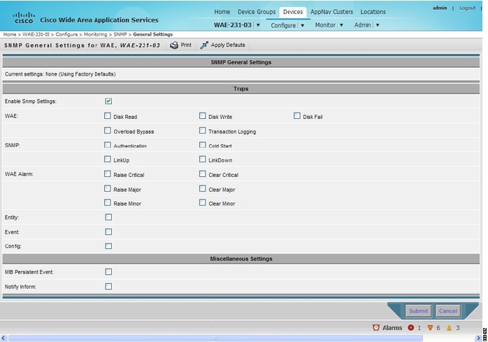
Step 3![]() Check the appropriate check boxes to enable SNMP traps.
Check the appropriate check boxes to enable SNMP traps.
A “Click Submit to Save” message appears in red next to the current settings when there are pending changes to be saved after you have applied default or device group settings. You can also revert to the previously configured window settings by clicking Reset. The Reset button is visible only when you apply default or device group settings to change the current device settings but the settings have not yet been submitted.
To enable SNMP traps from the CLI, you can use the snmp-server enable traps global configuration command.
To control access to the SNMP agent by an external SNMP server, use the snmp-server access-list global configuration command to apply an SNMP ACL.
Note![]() If you are using an SNMP server ACL, you must permit the loopback interface.
If you are using an SNMP server ACL, you must permit the loopback interface.
Note![]() If you override the device group settings from the SNMP General Settings window, the Central Manager deletes the SNMP community, SNMP group, SNMP user, SNMP view, and SNMP host settings. You are asked to confirm this behavior.
If you override the device group settings from the SNMP General Settings window, the Central Manager deletes the SNMP community, SNMP group, SNMP user, SNMP view, and SNMP host settings. You are asked to confirm this behavior.
To define additional SNMP traps for other MIB objects of interest to your particular configuration, see Defining SNMP Triggers to generate User-Defined Traps.
Defining SNMP Triggers to generate User-Defined Traps
To define additional SNMP traps for other MIB objects of interest to your particular configuration, follow these steps to create additional SNMP triggers:
Step 1![]() From the WAAS Central Manager menu, choose Devices > device-name ( or Device Groups > device-group-name).
From the WAAS Central Manager menu, choose Devices > device-name ( or Device Groups > device-group-name).
Step 2![]() Choose Configure > Monitoring > SNMP > Trigger. The SNMP Trigger List Entries window appears. The columns in this window are the same as the parameters described in Table 17-35 .
Choose Configure > Monitoring > SNMP > Trigger. The SNMP Trigger List Entries window appears. The columns in this window are the same as the parameters described in Table 17-35 .
Step 3![]() In the taskbar, click the Create New SNMP Trigger List Entry icon. The Creating New SNMP Trigger window appears. Table 17-35 describes the fields in this window.
In the taskbar, click the Create New SNMP Trigger List Entry icon. The Creating New SNMP Trigger window appears. Table 17-35 describes the fields in this window.
Step 4![]() In the appropriate fields, enter the MIB name, frequency, test, sample type, threshold value, and comments.
In the appropriate fields, enter the MIB name, frequency, test, sample type, threshold value, and comments.
Note![]() You can create valid triggers only on read-write and read-only MIB objects. If you create a trigger on a read-create MIB object, it is deleted from the Central Manager configuration after one one data feed poll cycle.
You can create valid triggers only on read-write and read-only MIB objects. If you create a trigger on a read-create MIB object, it is deleted from the Central Manager configuration after one one data feed poll cycle.
The new SNMP trigger is listed in the SNMP Trigger List window.
You can edit an SNMP trigger by clicking the Edit icon next to the MIB name in the SNMP Trigger List Entries window.
You can delete an SNMP trigger by clicking the Edit icon next to the MIB name and then clicking the Delete taskbar icon.
Note![]() If you delete any of the default SNMP triggers, they will be restored after a reload.
If you delete any of the default SNMP triggers, they will be restored after a reload.
Note![]() When you upgrade a WAE from an earlier version to the 6.0 version, all triggers are deleted.
When you upgrade a WAE from an earlier version to the 6.0 version, all triggers are deleted.
When you upgrade the Central Manager to 6.0, all the Device Group triggers will be copied to a WAE running a previous software version (if any) and all the Device Group triggers will be deleted. Also the Trigger Aggregate Settings will be set to false for all the WAES (running a version earlier than 6.0) that are being managed by the Central Manager (running version 6.0). This ensures that the DG triggers are no longer applied to any of the devices running a version earlier than 6.0.
Note![]() When you downgrade a WAE from a 6.0 to an earlier release all the IPv6 configurations will be removed. All the triggers and the monitor user configurations are deleted.
When you downgrade a WAE from a 6.0 to an earlier release all the IPv6 configurations will be removed. All the triggers and the monitor user configurations are deleted.
You can use the snmp trigger global configuration command to define SNMP traps from the CLI.
To control access to the SNMP agent by an external SNMP server, use the snmp-server access-list global configuration command to apply an SNMP ACL.
Note![]() If you are using an SNMP server ACL, you must permit the loopback interface.
If you are using an SNMP server ACL, you must permit the loopback interface.
Aggregating SNMP Triggers
An individual WAE device can have custom SNMP triggers defined and can belong to device groups that have other custom SNMP triggers defined.
In the SNMP Trigger List Entries window, the Aggregate Settings radio button controls how SNMP triggers are aggregated for an individual device, as follows:
- Choose Yes if you want to configure the device with all custom SNMP triggers that are defined for itself and for device groups to which it belongs.
- Choose No if you want to limit the device to just the custom SNMP triggers that are defined for itself.
When you change the setting, you get the following confirmation message: “This option will take effect immediately and will affect the device configuration. Do you wish to continue?” Click OK to continue.
Specifying the SNMP Host
Hosts are listed in the order in which they have been created. The maximum number of SNMP hosts that can be created is eight.
To specify the SNMP host, follow these steps:
Step 1![]() From the WAAS Central Manager menu, choose Devices > device-name ( or Device Groups > device-group-name).
From the WAAS Central Manager menu, choose Devices > device-name ( or Device Groups > device-group-name).
Step 2![]() Choose Configure > Monitoring > SNMP > Host. The SNMP Hosts window appears.
Choose Configure > Monitoring > SNMP > Host. The SNMP Hosts window appears.
Step 3![]() In the taskbar, click the Create New SNMP Host icon. The Creating New SNMP Host window appears. Table 17-36 describes the fields in this window.
In the taskbar, click the Create New SNMP Host icon. The Creating New SNMP Host window appears. Table 17-36 describes the fields in this window.
Step 4![]() Enter the hostname or IP address of an SNMP trap host, SNMP community or user name, security model to send notification, and retry count and timeout for inform requests.
Enter the hostname or IP address of an SNMP trap host, SNMP community or user name, security model to send notification, and retry count and timeout for inform requests.
To specify the SNMP host from the CLI, you can use the snmp-server host global configuration command.
Specifying the SNMP Community String
An SNMP community string is the password used to access an SNMP agent that resides on WAAS devices. There are two types of community strings: group and read-write. Community strings enhance the security of your SNMP messages.
Community strings are listed in the order in which they have been created. The maximum number of SNMP communities that can be created is ten. By default, an SNMP agent is disabled, and a community string is not configured. When a community string is configured, it permits read-only access to all agents by default.
To enable the SNMP agent and configure a community string to permit access to the SNMP agent, follow these steps:
Step 1![]() From the WAAS Central Manager menu, choose Devices > device-name ( or Device Groups > device-group-name).
From the WAAS Central Manager menu, choose Devices > device-name ( or Device Groups > device-group-name).
Step 2![]() Choose Configure > Monitoring > SNMP > Community. The SNMP Community Strings window appears.
Choose Configure > Monitoring > SNMP > Community. The SNMP Community Strings window appears.
Step 3![]() In the taskbar, click the Create New SNMP Community String icon. The Creating New SNMP Community String window appears. Table 17-37 describes the fields in this window.
In the taskbar, click the Create New SNMP Community String icon. The Creating New SNMP Community String window appears. Table 17-37 describes the fields in this window.
Step 4![]() In the appropriate fields, enter the community string, choose whether or not read-write access to the group is allowed, and enter the group name.
In the appropriate fields, enter the community string, choose whether or not read-write access to the group is allowed, and enter the group name.
To configure a community string from the CLI, you can use the snmp-server community global configuration command.
Creating SNMP Views
To restrict a group of users to view a specific MIB tree, you must create an SNMP view using the WAAS Central Manager GUI. Once you create the view, you need to create an SNMP group and SNMP users that belong to this group as described in later sections.
Views are listed in the order in which they have been created. The maximum number of views that can be created is ten.
To create a Version 2 SNMP (SNMPv2) MIB view, follow these steps:
Step 1![]() From the WAAS Central Manager menu, choose Devices > device-name ( or Device Groups > device-group-name).
From the WAAS Central Manager menu, choose Devices > device-name ( or Device Groups > device-group-name).
Step 2![]() Choose Configure > Monitoring > SNMP > View. The SNMP Views window appears.
Choose Configure > Monitoring > SNMP > View. The SNMP Views window appears.
Step 3![]() In the taskbar, click the Create New View icon. The Creating New SNMP View window appears. Table 17-38 describes the fields in this window.
In the taskbar, click the Create New View icon. The Creating New SNMP View window appears. Table 17-38 describes the fields in this window.
Step 4![]() In the appropriate fields, enter the view name, the family name, and the view type.
In the appropriate fields, enter the view name, the family name, and the view type.
Step 6![]() Create an SNMP group that will be assigned to this view as described in the section that follows.
Create an SNMP group that will be assigned to this view as described in the section that follows.
To create an SNMP view from the CLI, you can use the snmp-server view global configuration command.
Creating an SNMP Group
You must set up an SNMP group if you are going to create any SNMP users or want to restrict a group of users to view a specific MIB subtree.
Groups are listed in the order in which they have been created. The maximum number of SNMP groups that can be created is ten.
To define a user security model group, follow these steps:
Step 1![]() From the WAAS Central Manager menu, choose Devices > device-name ( or Device Groups > device-group-name).
From the WAAS Central Manager menu, choose Devices > device-name ( or Device Groups > device-group-name).
Step 2![]() Choose Configure > Monitoring > SNMP > Group. The SNMP Group Strings for WAE window appears.
Choose Configure > Monitoring > SNMP > Group. The SNMP Group Strings for WAE window appears.
Step 3![]() In the taskbar, click the Create New SNMP Group String icon. The Creating New SNMP Group String for WAE window appears. Table 17-39 describes the fields in this window.
In the taskbar, click the Create New SNMP Group String icon. The Creating New SNMP Group String for WAE window appears. Table 17-39 describes the fields in this window.
|
|
|
|---|---|
Name of the SNMP group. You can enter a maximum of 64 characters. This is a required field. |
|
Security model for the group. Choose one of the following options from the drop-down list:
Note |
|
Name of the view (a maximum of 64 characters) that enables you only to view the contents of the agent. By default, no view is defined. In order to provide read access to users of the group, a view must be specified. For information on creating SNMP views, see Creating SNMP Views. |
|
Name of the view (a maximum of 64 characters) that enables you to enter data and configure the contents of the agent. By default, no view is defined. For information on creating SNMP views, see Creating SNMP Views. |
|
Name of the view (a maximum of 64 characters) that enables you to specify a notify, inform, or trap. By default, no view is defined. For information on creating SNMP views, see Creating SNMP Views. |
Step 4![]() In the appropriate fields, enter the SNMP group configuration name, the security model, and the names of the read, write, and notify views.
In the appropriate fields, enter the SNMP group configuration name, the security model, and the names of the read, write, and notify views.
Step 6![]() Create SNMP users that belong to this new group as described in the section that follows.
Create SNMP users that belong to this new group as described in the section that follows.
To create an SNMP group from the CLI, you can use the snmp-server group global configuration command.
Creating an SNMP User
Users are listed in the order in which they have been created. The maximum number of users that can be created is ten.
To define a user who can access the SNMP engine, follow these steps:
Step 1![]() From the WAAS Central Manager menu, choose Devices > device-name ( or Device Groups > device-group-name).
From the WAAS Central Manager menu, choose Devices > device-name ( or Device Groups > device-group-name).
Step 2![]() Choose Configure > Monitoring > SNMP > User. A list of SNMP users for the device or device group appears.
Choose Configure > Monitoring > SNMP > User. A list of SNMP users for the device or device group appears.
Step 3![]() In the taskbar, click the Create New SNMP User icon. The Creating New SNMP User window appears. Table 17-40 describes the fields in this window.
In the taskbar, click the Create New SNMP User icon. The Creating New SNMP User window appears. Table 17-40 describes the fields in this window.
Step 4![]() In the appropriate fields, enter the username, the group to which the user belongs, the engine identity of the remote entity to which the user belongs, the authentication algorithm used to protect SNMP traffic from tampering, the user authentication parameters, and the authentication parameters for the packet.
In the appropriate fields, enter the username, the group to which the user belongs, the engine identity of the remote entity to which the user belongs, the authentication algorithm used to protect SNMP traffic from tampering, the user authentication parameters, and the authentication parameters for the packet.
To create an SNMP user from the CLI, you can use the snmp-server user global configuration command.
Additionally, if you want to set up a monitor user to monitor the configured triggers, you can select it from the Monitor User Settings drop-down box.
Any SNMP V3 user can be configured as a Monitor User. All the SNMP users created with a group having V3 authentication other than v3-private are eligible to be a Monitor User. A monitor user cannot be deleted, while being in that role. Similarly the corresponding monitor user group also cannot be deleted when a monitor user is configured with that group.
To create a monitor user from the CLI, you can use the snmp-server monitor user global configuration command.
Configuring SNMP Asset Tag Settings
To configure SNMP asset tag settings, which create values in the CISCO-ENTITY-ASSET-MIB, follow these steps:
Step 1![]() From the WAAS Central Manager menu, choose Devices > device-name ( or Device Groups > device-group-name).
From the WAAS Central Manager menu, choose Devices > device-name ( or Device Groups > device-group-name).
Step 2![]() Choose Configure > Monitoring > SNMP > Asset Tag. The SNMP Asset Tag Settings window appears.
Choose Configure > Monitoring > SNMP > Asset Tag. The SNMP Asset Tag Settings window appears.
Step 3![]() In the Asset Tag Name field, enter a name for the asset tag.
In the Asset Tag Name field, enter a name for the asset tag.
To configure SNMP asset tag settings from the CLI, you can use the asset tag global configuration command.
Configuring SNMP Contact Settings
To configure SNMP contact settings, follow these steps:
Step 1![]() From the WAAS Central Manager menu, choose Devices > device-name ( or Device Groups > device-group-name).
From the WAAS Central Manager menu, choose Devices > device-name ( or Device Groups > device-group-name).
Step 2![]() Choose Configure > Monitoring > SNMP > Contact Information. The SNMP Contact Settings window appears.
Choose Configure > Monitoring > SNMP > Contact Information. The SNMP Contact Settings window appears.
Step 3![]() Enter a contact name and location in the provided fields.
Enter a contact name and location in the provided fields.
To configure SNMP contact settings from the CLI, you can use the snmp-server contact global configuration command.
Configuring SNMP Trap Source Settings
To configure the source interface from which SNMP traps are sent, follow these steps:
Step 1![]() From the WAAS Central Manager menu, choose Devices > device-name. (This setting is not supported from device groups.)
From the WAAS Central Manager menu, choose Devices > device-name. (This setting is not supported from device groups.)
Step 2![]() Choose Configure > Monitoring > SNMP > Trap Source. The SNMP Trap Source Settings window appears.
Choose Configure > Monitoring > SNMP > Trap Source. The SNMP Trap Source Settings window appears.
Step 3![]() From the Trap Source drop-down list, choose the interface to be used as the trap source. From the available physical, standby, and port-channel interfaces, only those with IP addresses are shown in the list. For vWAAS devices, virtual interfaces with assigned IP addresses are shown in the list.
From the Trap Source drop-down list, choose the interface to be used as the trap source. From the available physical, standby, and port-channel interfaces, only those with IP addresses are shown in the list. For vWAAS devices, virtual interfaces with assigned IP addresses are shown in the list.
Note![]() An interface assigned as a trap source cannot be removed until it is unassigned as a trap source.
An interface assigned as a trap source cannot be removed until it is unassigned as a trap source.
To configure SNMP trap source settings from the CLI, you can use the snmp-server trap-source global configuration command.
 Feedback