- Preface
- Introduction to Cisco vWAAS
- Configuring Cisco vWAAS and Viewing vWAAS Components
- Cisco vWAAS on Cisco ISR-WAAS
- Cisco vWAAS on VMware ESXi
- Cisco vWAAS on Microsoft Hyper-V
- Cisco vWAAS on RHEL KVM, KVM on CentOS, and KVM in SUSE Linux
- Cisco vWAAS on Cisco ENCS 5400-W Series
- Cisco vWAAS on Cisco CSP 5000-W Series
- Cisco vWAAS with Cisco Enterprise NFVIS
- Cisco vWAAS with Akamai Connect
- Cisco vWAAS in Cloud Computing Systems
- Troubleshooting Cisco vWAAS
- Cisco vWAAS on Cisco CSP 5000-W Series
- Cisco CSP 5000-W Hardware Features and Specifications
- Deploying, Registering, and Configuring Cisco vWAAS on Cisco CSP 5000-W
Cisco vWAAS on Cisco CSP 5000-W Series
This chapter describes Cisco vWAAS on the Cisco Cloud Services Platform, 5000-W Series (Cisco CSP 5000-W Series) appliance.
Cisco vWAAS on Cisco CSP 5000-W Series
This section contains the following topics:
- About the Cisco CSP 5000-W Series
- Cisco CSP 5000-W Models Supported for Cisco vWAAS
- Cisco vWAAS on Cisco CSP 5000-W with Akamai Connect
- Traffic Interception Methods
About the Cisco CSP 5000-W Series
The Cisco Cloud Services Platform for WAAS (CSP-W) is a Cisco open x86 hardware platform for deployment of Cisco datacenter Network Functions Virtualization (VNFs). Cisco CSP 5000-W Series contains an embedded KVM CentOS hypervisor, and enables you to monitor and manage the lifecycle of vWAAS on NFVIS.
The Cisco CSP 5000-W Series enables you to quickly deploy any Cisco network virtual service through a simple, built-in, native GUI, Cisco WAAS CLI, or Representational State Transfer (REST) API.

Note![]() For Cisco vWAAS in Cisco WAAS Version 6.4.3e and later, Cisco devices use the strong password enforcement feature. After initial login, you must change the default password for the Cisco WAAS administrator account, and the NFVIS administrator account for vWAAS on the ENCS 5400-W series and the CSP 5000-W series. For more information, see Strong Password Enforcement in the chapter “Cisco vWAAS on Cisco ENCS 5400-W Series.”
For Cisco vWAAS in Cisco WAAS Version 6.4.3e and later, Cisco devices use the strong password enforcement feature. After initial login, you must change the default password for the Cisco WAAS administrator account, and the NFVIS administrator account for vWAAS on the ENCS 5400-W series and the CSP 5000-W series. For more information, see Strong Password Enforcement in the chapter “Cisco vWAAS on Cisco ENCS 5400-W Series.”
Cisco CSP 5000-W Models Supported for Cisco vWAAS
Three Cisco CSP 5000-W models are supported for Cisco vWAAS:
- Cisco CSP 5228-W (12,000 connections): For Cisco vWAAS-12000
- Cisco CSP 5228-W (50,000 connections): For Cisco vWAAS-50000
- Cisco CSP 5436-W (150,000 connections): For Cisco vWAAS-150000
These Cisco CSP 5000-W models replace three End-of-Sale and End-of-Life (EOS and EOL) Cisco WAVE models. Table 8-1 shows the corresponding Cisco CSP 5000-W and EOS and EOL Cisco WAVE models, the supported Cisco vWAAS models, and the Cisco UCS model used with CSP 5000-W.
Table 8-1 Cisco CSP 5000-W and Replaced and Supported Models
|
|
|
|
|
|---|---|---|---|
For more information on the EOS and EOL Cisco WAVE models, see the End-of-Sale and End-of-Life Announcement for the Cisco WAVE 294, 594, 694, 7541, 7571 and 8541.
Note![]() There is no Product Returns and Replacement (RMA) process for Cisco CSP 5000-W devices or EOS and EOL Cisco WAVE devices.
There is no Product Returns and Replacement (RMA) process for Cisco CSP 5000-W devices or EOS and EOL Cisco WAVE devices.
Cisco vWAAS on Cisco CSP 5000-W with Akamai Connect
Consider the following guidelines for Cisco vWAAS on Cisco CSP 5000-W with Akamai Connect:
- As shown in Table 8-2, a fourth disk is required for Cisco vWAAS on Cisco CSP 5000-W with Akamai Connect caching.
- Cisco CSP 5000-W devices have fixed resources. Therefore the memory on each device remains the same with or without Akamai Connect enabled.
Table 8-2 System Requirements for Cisco vWAAS on Cisco CSP 5000-W with Akamai Connect
|
|
|
|
|
|
|---|---|---|---|---|
|
|
|
|||
Traffic Interception Methods
Cisco vWAAS on the Cisco CSP 5000-W platform supports off-path deployment for WCCP and Cisco AppNav traffic interception. However, the Cisco AppNav I/O Module (Cisco AppNav IOM) is not supported on the Cisco CSP 5000-W platform.
Cisco CSP 5000-W Hardware Features and Specifications
Table 8-3 shows the specifications for each Cisco CSP 5000-W model used with Cisco vWAAS.
Note the following details about these three Cisco CSP 5000-W models:
- The dedicated management port on the device is used for CIMC connectivity.
- The first port on the four-port 1-G (I350) card is used for Cisco NFVIS management.
- We recommend that you use CSP-SFPs (Intel) to connect the Intel X520-DA2 10-Gbps ports on both sides of end-to-end connections.
Table 8-3 Specifications for Cisco CSP 5000-W Models Used with Cisco vWAAS
For more information on RAID configuration, see the Cisco UCS Servers RAID Guide.
Deploying, Registering, and Configuring Cisco vWAAS on Cisco CSP 5000-W
This section contains the following topics:
- Workflow for Deploying, Registering, and Configuring Cisco vWAAS on Cisco CSP 5000-W
- Installing Cisco vWAAS on a Cisco CSP 5000-W Device
- Configuring a Port Channel and Standby Interface
- Registering or Deregistering a Cisco CSP 5000-W Device with the Cisco WAAS Central Manager
Workflow for Deploying, Registering, and Configuring Cisco vWAAS on Cisco CSP 5000-W
|
|
|
|---|---|
2. |
|
|
|
Installing Cisco vWAAS on a Cisco CSP 5000-W Device
Cisco CSP 5000-W is a bundled solution and is shipped with a pre-installed image
To install any of the three supported Cisco vWAAS models on the supported Cisco CSP 5000-W device, perform the following tasks:
- Use the following show commands to verify that all hardware details for the CSP 5000-W device are displayed correctly.
–![]() show version: Verifies that the Cisco WAAS version is Version 6.4.3a or later.
show version: Verifies that the Cisco WAAS version is Version 6.4.3a or later.
–![]() show tfo detail: Verifies the number of Transport Flow Optimization (TFO) connections depending on the Cisco vWAAS model.
show tfo detail: Verifies the number of Transport Flow Optimization (TFO) connections depending on the Cisco vWAAS model.
–![]() show hardware: Validates the CPU and memory depending on the Cisco vWAAS model.
show hardware: Validates the CPU and memory depending on the Cisco vWAAS model.
–![]() show inventory: Validates the PID depending on the Cisco vWAAS model.
show inventory: Validates the PID depending on the Cisco vWAAS model.
Configuring a Port Channel and Standby Interface
Configuring a Port Channel Interface
To provide increased bandwidth and redundancy, a port channel bundles individual interfaces within these NIC modules:
For fiber connectivity, Intel SFP+ is required for connecting the Intel X520-DA2 10-Gbps two-port NIC (2x10-GB Fiber interfaces).
Port channeling load balances traffic across physical interfaces. The port channel stays operational as long as at least one physical interface within the port channel is operational.
You create a port channel by bundling compatible interfaces. You can configure and run either static port channels or ports channels running the Link Aggregation Control Protocol (LACP). Standby provides aggregation of several physical links into a logical one, but only for the purpose of furnishing fault-tolerance.
The following CLI commands are used in the context of port channels:
- To configure a port channel group for a network interface, use the (config-if) channel-group command:
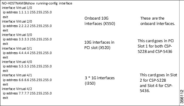
Figure 8-1 shows an annotated output for the show running-config interface command:
Figure 8-1 Cisco WAAS CLI show running-config Annotated Output
Configuring a Standby Interface
You can create two port channel groups and use them as the active and backup members of a standby group. The standby interface has two modes:
- Active-backup mode: Implements the standby interface and provides fault tolerance. Only one server interface in the bond is active. A different server interface becomes active only if the active server interface fails.
- SRC-DST-IP-PORT mode: Provides load balancing and fault tolerance. In this mode, all the frames between the same source and the same destination use the same link.
The following CLI commands are used in the context of a standby interface:
- To configure an interface to be a standby for another interface, use the (config-if) standby command:
Registering or Deregistering a Cisco CSP 5000-W Device with the Cisco WAAS Central Manager
Registering a Cisco CSP 5000-W Device with the Cisco WAAS Central Manager
To register a Cisco WAAS device or Cisco vWAAS device with the WAAS Central Manager, follow these steps:
Step 1![]() At the Cisco datacenter CSP 5000-W CLI, enter the Cisco WAAS Central Manager IP address, for example: 10.78.99.141:
At the Cisco datacenter CSP 5000-W CLI, enter the Cisco WAAS Central Manager IP address, for example: 10.78.99.141:
Note![]() The IP address configured in the Cisco NFVIS management port cannot be accessed from the Cisco WAAS Central Manager.
The IP address configured in the Cisco NFVIS management port cannot be accessed from the Cisco WAAS Central Manager.
Step 2![]() Use the cms command to register the Cisco CSP 5000-W device:
Use the cms command to register the Cisco CSP 5000-W device:
Step 3![]() Use the copy running-config startup-config command to preserve the running configuration.
Use the copy running-config startup-config command to preserve the running configuration.
Note![]() If you do not use the copy running-config startup-config command, the management service will not be started on reload, and the Cisco WAAS Central Manager will show the node as Offline.
If you do not use the copy running-config startup-config command, the management service will not be started on reload, and the Cisco WAAS Central Manager will show the node as Offline.
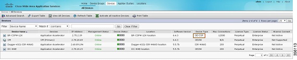
Step 4![]() After the device is registered, it is displayed in the Cisco WAAS Central Manager as OE-CSP (Figure 8-2).
After the device is registered, it is displayed in the Cisco WAAS Central Manager as OE-CSP (Figure 8-2).
Figure 8-2 Cisco OE-CSP Displayed in the WAAS Central Manager Device Listings Window
Step 5![]() To view the Cisco CSP 5000-W device in the dashboard, choose Devices > device-name > Dashboard.
To view the Cisco CSP 5000-W device in the dashboard, choose Devices > device-name > Dashboard.
The Device Dashboard window is displayed. Information displayed for the device includes device model, IP address, interception method, and device-specific charts.
Step 6![]() You can also use the Cisco CSP 5000-W CLI to view device information:
You can also use the Cisco CSP 5000-W CLI to view device information:
Deregistering a Cisco CSP 5000-W Device
To deregister a Cisco CSP 5000-W device, follow these steps.
Step 1![]() At the Cisco datacenter CSP 5000-W CLI, use the cms deregister command to deregister the device:
At the Cisco datacenter CSP 5000-W CLI, use the cms deregister command to deregister the device:
Step 2![]() Click yes to initiate the deregistering process. The system displays the following status messages.
Click yes to initiate the deregistering process. The system displays the following status messages.
Step 3![]() Use the copy running-config startup-config command to preserve the running configuration.
Use the copy running-config startup-config command to preserve the running configuration.
Note![]() If you do not use the copy running-config startup-config command, the management service will not be started on reload, and the Cisco WAAS Central Manager will show the node as Offline.
If you do not use the copy running-config startup-config command, the management service will not be started on reload, and the Cisco WAAS Central Manager will show the node as Offline.
CLI Commands Used with Cisco vWAAS on Cisco CSP 5000-W
Table 8-4 shows the CLI commands used with Cisco vWAAS on Cisco CSP 5000-W.
Table 8-4 CLI Commands used with Cisco vWAAS on Cisco CSP 5000-W
Upgrade and Downgrade Guidelines for Cisco vWAAS on Cisco CSP 5000-W
Consider the following upgrade and downgrade guidelines:
–![]() Upgrade is supported for the Cisco vWAAS bundled image in Cisco WAAS Version 6.4.3a and later, and the associated Cisco NFVIS version used with Cisco WAAS.
Upgrade is supported for the Cisco vWAAS bundled image in Cisco WAAS Version 6.4.3a and later, and the associated Cisco NFVIS version used with Cisco WAAS.
–![]() Downgrade is not supported for Cisco vWAAS for Cisco WAAS versions earlier than Cisco WAAS 6.4.3a.
Downgrade is not supported for Cisco vWAAS for Cisco WAAS versions earlier than Cisco WAAS 6.4.3a.
–![]() When there is more than one device type present at the Device Group level, the Cisco WAAS Central Manager supports upgrade and downgrade that is supported for each device type.
When there is more than one device type present at the Device Group level, the Cisco WAAS Central Manager supports upgrade and downgrade that is supported for each device type.
Note![]() Cisco CSP 5000-W devices run with specific Cisco vWAAS and Cisco NFVIS versions. We recommend that you upgrade Cisco vWAAS and Cisco NFVIS together; do not upgrade each of these separately. For more information, Upgrade Guidelines for Cisco Enterprise NFVIS in the chapter “Cisco vWAAS with Cisco Enterprise NFVIS,
Cisco CSP 5000-W devices run with specific Cisco vWAAS and Cisco NFVIS versions. We recommend that you upgrade Cisco vWAAS and Cisco NFVIS together; do not upgrade each of these separately. For more information, Upgrade Guidelines for Cisco Enterprise NFVIS in the chapter “Cisco vWAAS with Cisco Enterprise NFVIS,
 Feedback