Cisco Vision Network, Server, and Video Headend Requirements Guide, Release 6.3
Bias-Free Language
The documentation set for this product strives to use bias-free language. For the purposes of this documentation set, bias-free is defined as language that does not imply discrimination based on age, disability, gender, racial identity, ethnic identity, sexual orientation, socioeconomic status, and intersectionality. Exceptions may be present in the documentation due to language that is hardcoded in the user interfaces of the product software, language used based on RFP documentation, or language that is used by a referenced third-party product. Learn more about how Cisco is using Inclusive Language.
- Updated:
- October 28, 2020
Chapter: Deployment and Requirements- Expanded Topics
- Multicast
- Multicast Applications
- Protocol Independent Multicast
- Multicast Redundancy Strategies
- Analysis of Multicast and Failover Scenarios
- Network and Precision Time Protocols (NTP & PTP)
- PTP for Video Wall Synchronization
- Fiber Uplinks
- Wireless Access
- Digital Media Player Topics
- Cisco Vision Dynamic Signage Director on the Network - Failover
Deployment and Requirements - Expanded Topics
The topics covered in this chapter expand upon the checklist of requirements provided earlier and provides details on more technical and operational aspects of the networking requirements.
Multicast
The digital signage network uses IP Multicast for delivering a number of services. The unique requirements of these services are met using Protocol Independent Multicast (PIM) Sparse mode routing with two redundancy strategies. Earlier in this document differences in implementations between source-specific multicast (SSM) and rendezvous point (RP) were pointed out, and in this section, we’ll provide a more detailed explanation into how they work in normal and failover scenarios. If implementing a new install, it is preferable to use the SSM guidelines instead of configuring RPs which is a supported legacy design architecture. Either method is very similar on how addressing is done on the video ingress, but they are different with regards to PIM communications and how the traffic gets forwarded from the source to the receiver.
Multicast Applications
There are three applications that use IP multicast and leverage these two different redundancy strategies:
■![]() Video channels streamed to Digital Media Players (DMPs) attached. Uses Prioritycast RP Multicast Topology.
Video channels streamed to Digital Media Players (DMPs) attached. Uses Prioritycast RP Multicast Topology.
■![]() Multicast control of DMP states (i.e., what is displayed on the TVs). Uses Anycast RP Multicast Topology.
Multicast control of DMP states (i.e., what is displayed on the TVs). Uses Anycast RP Multicast Topology.
Cisco Vision Director In-Suite Video
■![]() IP Multicast video streamed from a Digital Media Player.
IP Multicast video streamed from a Digital Media Player.
Note : To control the distribution of video, use a TTL=1 to limit the video to the local VLAN or use access control lists (ACLs) or multicast boundaries to limit what VLANs can request the video.
Protocol Independent Multicast
The IP Multicast design employs Protocol Independent Multicast (PIM) Sparse mode routing with Rendezvous Point (RP) redundancy in the following manner:.
■![]() Because PIM Sparse mode operates in an on-demand fashion, receivers must request a video stream using an internet group management protocol (IGMP) join request.
Because PIM Sparse mode operates in an on-demand fashion, receivers must request a video stream using an internet group management protocol (IGMP) join request.
■![]() This request is received by the receiver’s local switch and is directed to a pre-configured Rendezvous Point (RP). The RP is where sources and receivers register and is how they find each other in the network.
This request is received by the receiver’s local switch and is directed to a pre-configured Rendezvous Point (RP). The RP is where sources and receivers register and is how they find each other in the network.
■![]() Once registered, a tree is built to connect sources and receivers that the multicast stream will traverse.
Once registered, a tree is built to connect sources and receivers that the multicast stream will traverse.
■![]() Reverse Path Forwarding (RPF) using the network’s unicast routing table is used to derive the shortest paths (or branches of the tree) between sources and receivers.
Reverse Path Forwarding (RPF) using the network’s unicast routing table is used to derive the shortest paths (or branches of the tree) between sources and receivers.
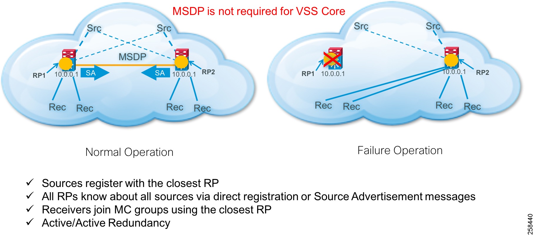
Anycast
The Anycast strategy uses two or more RPs with the same IP address and mask and Multicast Source Discovery Protocol (MSDP) to distribute multicast source registration information among the RPs. MSDP is not used in virtual switching system (VSS) core designs. It is only used in the collapsed core and access designs (e.g., Cisco Nexus) or with other manufacturers that have a single control plane. In SSM implementations, MSDP is retained but RPs are not needed.
This methodology ensures that each RP knows about all sources and can facilitate building an RP tree between the source and receiver.
Operation and Configuration
1.![]() In Anycast RP, all the RPs are configured to be MSDP peers of each other.
In Anycast RP, all the RPs are configured to be MSDP peers of each other.
2.![]() When a multicast source (e.g., Cisco Vision Dynamic Signage Director) registers with one RP, a Source Advertisement (SA) message will be sent to the other RPs informing them that there is an active source for a particular multicast group.
When a multicast source (e.g., Cisco Vision Dynamic Signage Director) registers with one RP, a Source Advertisement (SA) message will be sent to the other RPs informing them that there is an active source for a particular multicast group.
3.![]() The result is that each RP will know about the active sources in the area of the other RPs.
The result is that each RP will know about the active sources in the area of the other RPs.
4.![]() If any of the RPs were to fail, IP routing would converge.
If any of the RPs were to fail, IP routing would converge.
5.![]() New sources would register with the next closest RP.
New sources would register with the next closest RP.
6.![]() Receivers would join toward the new RP and connectivity would be maintained.
Receivers would join toward the new RP and connectivity would be maintained.
Note: The RP is normally needed only to start new sessions with sources and receivers. The RP facilitates the shared tree so that sources and receivers can directly establish a multicast data flow. If a multicast data flow is already directly established between a source and the receiver, then an RP failure will not affect that session. Anycast RP ensures that new sessions with sources and receivers can begin at any time.
General IP Multicast traffic is handled by PIM Sparse-mode and the Anycast redundancy strategy. The use of PIM Sparse-mode is consistent with the Prioritycast stategy. However, MSDP is used to support RP redundancy.
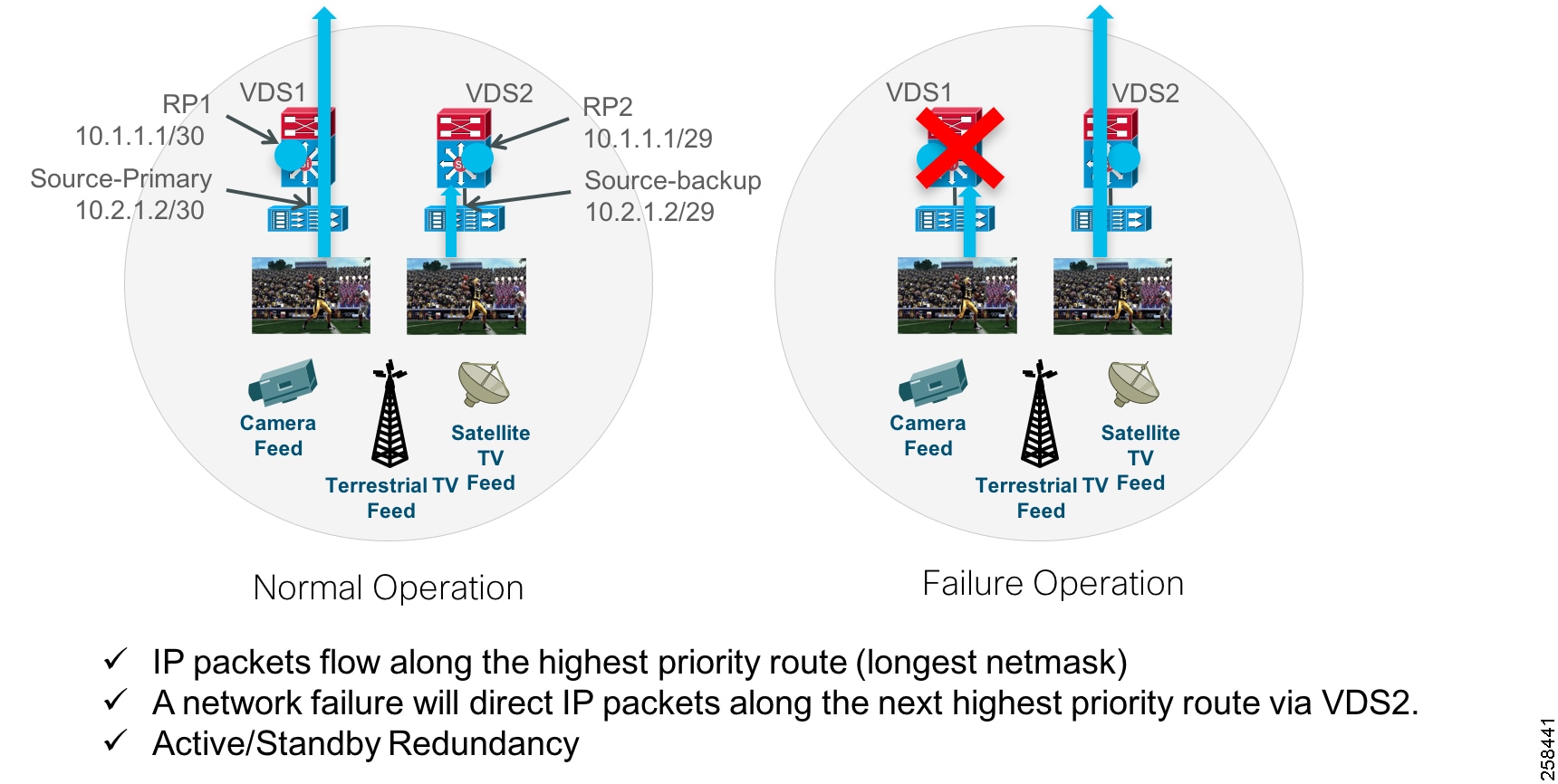
Prioritycast
Because PIM Sparse mode operates in an on-demand fashion, receivers must request a video stream using an IGMP join request. This request is received by the receiver’s local switch and is directed to a pre-configured RP. The RP is where sources and receivers register and is how they find each other in the network.
Once registered, a tree is built to connect sources and receivers that the MC stream will traverse. Reverse Path Forwarding (RPF) using the network’s unicast routing table is used to derive the shortest paths (or branches of the tree) between sources and receivers. Prioritycast uses unicast routing mechanisms to have the network act as the arbiter of what source streams traverse the network and when. This is how the active/standby redundancy strategy is implemented. Below is a description of how this is accomplished.
1.![]() Prioritycast uses duplicate multicast video sources, each source connected to a separate VDS switch.
Prioritycast uses duplicate multicast video sources, each source connected to a separate VDS switch.
2.![]() Each primary multicast source, RP, and it’s backup use identical IP addresses with differing network masks.
Each primary multicast source, RP, and it’s backup use identical IP addresses with differing network masks.
3.![]() The primary MC source and RP uses the longest network mask and is the active source and RP on the network.
The primary MC source and RP uses the longest network mask and is the active source and RP on the network.
4.![]() If the primary VDS switch or uplinks or primary MC video source Ethernet link fail, the network will converge and place the backup MC video source onto the network. The transition is transparent to the video receivers due to identical source IP addresses.
If the primary VDS switch or uplinks or primary MC video source Ethernet link fail, the network will converge and place the backup MC video source onto the network. The transition is transparent to the video receivers due to identical source IP addresses.
Figure 3 Prioritycast in Action
Multicast design uses these attributes:
■![]() Uses PIM Sparse Mode multicast routing protocol.
Uses PIM Sparse Mode multicast routing protocol.
■![]() Uses a set RP on the Core switches for general multicast support.
Uses a set RP on the Core switches for general multicast support.
■![]() Uses a set of RP on the VDS for video multicast support.
Uses a set of RP on the VDS for video multicast support.
■![]() For general multicast DMP control, Anycast RP and MSDP for RP redundancy is used (Nexus core switches). For SSM, MSDP is still used for Anycast but without RPs.
For general multicast DMP control, Anycast RP and MSDP for RP redundancy is used (Nexus core switches). For SSM, MSDP is still used for Anycast but without RPs.
■![]() Anycast RP provides an active/active redundancy strategy.
Anycast RP provides an active/active redundancy strategy.
■![]() Uses Prioritycast RP for source and RP redundancy for video multicast.
Uses Prioritycast RP for source and RP redundancy for video multicast.
■![]() Prioritycast RP provides an active/standby redundancy strategy.
Prioritycast RP provides an active/standby redundancy strategy.
■![]() Uses ACLs and MC Boundaries to limit MC to their designated areas.
Uses ACLs and MC Boundaries to limit MC to their designated areas.
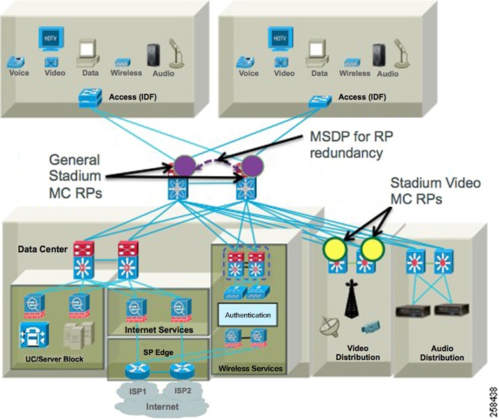
Figure 4 Connected Stadium Multicast Architecture Overview
Multicast Redundancy Strategies
Anycast and Prioritycast RP redundancy strategies have some telling attributes about how multicast traffic is handled and the impact it has on the network and endpoints. Below are the attributes of each strategy.
Anycast
■![]() Provides Source and RP Redundancy in an Active/Active redundancy model.
Provides Source and RP Redundancy in an Active/Active redundancy model.
■![]() Simple to implement. Sources can be anywhere in the network with no special IP addressing.
Simple to implement. Sources can be anywhere in the network with no special IP addressing.
■![]() An RP is configured with the same address and on each of the Core switches.
An RP is configured with the same address and on each of the Core switches.
■![]() MSDP netmask is configured between the Nexus Core switches and their respective RPs to share source information.
MSDP netmask is configured between the Nexus Core switches and their respective RPs to share source information.
Prioritycast
■![]() Provides Source and RP Redundancy in an Active/Standby redundancy model.
Provides Source and RP Redundancy in an Active/Standby redundancy model.
■![]() More complex to implement. Redundant sources must use duplicate addressing with different masks.
More complex to implement. Redundant sources must use duplicate addressing with different masks.
■![]() Provides a single source stream on the network at a time. This is important to reduce the amount of traffic on the network, especially heavy traffic like video.
Provides a single source stream on the network at a time. This is important to reduce the amount of traffic on the network, especially heavy traffic like video.
■![]() Because the network controls what source traffic is allowed on the network, no vendor proprietary source sync protocol is required between sources to trigger the backup source to start streaming.
Because the network controls what source traffic is allowed on the network, no vendor proprietary source sync protocol is required between sources to trigger the backup source to start streaming.
■![]() Because only a single stream is on the network at any one time, the video endpoints do not have to arbitrate between two duplicate video streams. This means lower endpoint complexity and processing power are required.
Because only a single stream is on the network at any one time, the video endpoints do not have to arbitrate between two duplicate video streams. This means lower endpoint complexity and processing power are required.
Analysis of Multicast and Failover Scenarios
This topic will illustrate in detail how multicast behaves normally and during failover of source or RP with Prioritycast RP and multicast sources.
Background
The RP is a loop back address defined on each VDS but with different subnet mask, /30 (primary VDS), /29 (secondary VDS). The RP-address is defined on each VDS and the core VSS switch. The RP-address statement has an access list associated with it that defines what multicast addresses are associated with that RP address. Each VDS has a directly connected source via routed interface or VLAN with a L3 netmask of /30 (primary VDS), and /29 (secondary VDS).
Each loopback on the VDS switches has the same IP address as the other, and only the netmask differs. In most circumstances, this should also be true for the multicast source unicast IP address. They should be the same on each VDS switch. The SVI/routed interface should also have the same IP address but with different netmasks.
Normal Operation
The VDS prioritycast loopback RP addresses are up on both VDS switches. There are multicast packets coming into each VDS switch via the routed/VLAN with netmask of /30, /29, respectively. The source IP address of the multicast is the same for each unique multicast addresses on each VDS switch (from the same source on both VDS1 and VDS2).
1.![]() The Route table on each VDS switch will show a directly connected route for loopback and each routed/SVI source network. Each switch will also learn of the other networks via routing protocol, but the connected routes will be preferred because their administrative distance (AD) is 0 in the routing table.
The Route table on each VDS switch will show a directly connected route for loopback and each routed/SVI source network. Each switch will also learn of the other networks via routing protocol, but the connected routes will be preferred because their administrative distance (AD) is 0 in the routing table.
2.![]() Route table on the VSS core will only know about the routing protocol advertisements and will learn of the RP and routed/SVI source networks. The VSS core will insert the network with the longest mask into the routing table for both RP and routed/SVI networks.
Route table on the VSS core will only know about the routing protocol advertisements and will learn of the RP and routed/SVI source networks. The VSS core will insert the network with the longest mask into the routing table for both RP and routed/SVI networks.
3.![]() VSS core will map via the RP-address statement multicast source address as defined by the associated access list.
VSS core will map via the RP-address statement multicast source address as defined by the associated access list.
4.![]() Then an IGMP Join comes in from a receiver into the VSS switch.
Then an IGMP Join comes in from a receiver into the VSS switch.
a.![]() The Join contains a multicast group to be joined.
The Join contains a multicast group to be joined.
b.![]() VSS core will see if the joined group matches the access list associated with the RP-address statement.
VSS core will see if the joined group matches the access list associated with the RP-address statement.
c.![]() VSS core finds a match defined to an RP-address statement and the associated multicast range defined by the access list. The address defined by the RP-address statement is the prioritycast loopback address of each VDS switch.
VSS core finds a match defined to an RP-address statement and the associated multicast range defined by the access list. The address defined by the RP-address statement is the prioritycast loopback address of each VDS switch.
d.![]() VSS core looks up the address in its routing table and finds two matches for the loopback address. It will see both /29 and /30 routing table entries.
VSS core looks up the address in its routing table and finds two matches for the loopback address. It will see both /29 and /30 routing table entries.
e.![]() Switch sends the PIM join upstream to the RP and the unicast route with the longest match, out the interface to VDS1 is selected because it has the /30 mask.
Switch sends the PIM join upstream to the RP and the unicast route with the longest match, out the interface to VDS1 is selected because it has the /30 mask.
f.![]() VDS1 already has all multicast routes built in its routing table for each incoming group coming from the source attached to the /29,/30 routed or SVI interface.
VDS1 already has all multicast routes built in its routing table for each incoming group coming from the source attached to the /29,/30 routed or SVI interface.
g.![]() VDS1 has a (*,G) and source specific (S,G) built for each source. The (*,G) is the anysource definition and the (S,G) is the source specific definition for each multicast address.
VDS1 has a (*,G) and source specific (S,G) built for each source. The (*,G) is the anysource definition and the (S,G) is the source specific definition for each multicast address.
h.![]() VDS1 after receiving the join from the VSS core also looks up the RP-address statement as well as the associated access list. The VDS1 finds that the RP is a directly connected loopback address and has a match for the requested group in the access list associated with the RP-address statement. VDS1 looks up the requested group in its multicast routing table and finds a match.
VDS1 after receiving the join from the VSS core also looks up the RP-address statement as well as the associated access list. The VDS1 finds that the RP is a directly connected loopback address and has a match for the requested group in the access list associated with the RP-address statement. VDS1 looks up the requested group in its multicast routing table and finds a match.
i.![]() VDS1 adds the outgoing interface to the *,G for the interface that the join came in on towards the VSS core and forwards one packet to the VDS core.
VDS1 adds the outgoing interface to the *,G for the interface that the join came in on towards the VSS core and forwards one packet to the VDS core.
j.![]() VDS1 will also build the same for the (*,G) entry. With the one packet it received, it will inspect the source IP of the multicast packet then send a shortest path tree (SPT) join towards the network of the source IP (VDS1).
VDS1 will also build the same for the (*,G) entry. With the one packet it received, it will inspect the source IP of the multicast packet then send a shortest path tree (SPT) join towards the network of the source IP (VDS1).
k.![]() VSS core adds the outgoing interface to the *,G for the interface that the join came in on towards the receiver VLAN. VSS core will also build the same for the S,G entry.
VSS core adds the outgoing interface to the *,G for the interface that the join came in on towards the receiver VLAN. VSS core will also build the same for the S,G entry.
l.![]() VSS core then floods the requested group to the receiver VLAN.
VSS core then floods the requested group to the receiver VLAN.
One important thing to note here is the *,G versus the S,G because it will play an important part of the decision making process in any failover configuration. There are two important concepts at play here. One is SPT and the other is rendezvous point tree (RPT). SPT is the source specific tree that gets built, this is the S,G entry (this only happens after RPT in non SSM, (ASM configurations). The S,G is the entry associated with the best unicast reverse path to the multicast source IP itself and is source specific multicast (SSM). The RPT is the shared anysource tree or RP tree, anysource multicast (ASM). The *,G RPT entry is associated with the best unicast reverse path to the RP address as defined by the rp-address statement and associated ACL.
In an ASM (anysource *,G) environment, it’s important to understand that the RP is the single point of registration for both multicast sources and receivers. This is because joins do not contain any source information, the RP is tasked with keeping track of all incoming multicast sources as well as all incoming requests from downstream PIM neighbors (receivers - DMPs). The RPT mechanism for joins is always the first to occur in RP designs because receivers and downstream PIM neighbors do not know the unicast source IP of the multicast address. After the join reaches the RP via the RPT from a downstream PIM neighbor, a switchover occurs. The RPT will forward an ASM multicast packet to the downstream PIM neighbor tree that made the request. Once each downstream L3 neighbor receives this packet, it then builds its own SPT/SSM entry in its multicast routing table and the downstream neighbor no longer needs the RPT or RP to receive the multicast because it knows the unicast path towards the source and multicast path in which to send PIM joins towards. This is called the RPT to SPT cutover. The cutover in modern IOS happens with a 0 bit threshold, which means that the neighbor (VSS core) will switch over to the SPT (SSM) path upon receiving the first packet from the RP, or a PIM message from the RP with the source IP of the source multicast group, and it does this based on the unicast route table for the unicast source IP of the group. After this point, RP is not used and why you always see both *,G and S,G entry in all the downstream multicast routing tables.
Failure Case: Source Network Fails; RP Does Not Fail
In this scenario, the same overall steps from above still occur until we get to step E. Let’s take into account three sub scenarios:
1.![]() one with an existing *,G/S,G already built before the failure
one with an existing *,G/S,G already built before the failure
2.![]() a new one to be built after the failure of the source VLAN SVI/routed interface but before the multicast routes on VDS1 timeout
a new one to be built after the failure of the source VLAN SVI/routed interface but before the multicast routes on VDS1 timeout
3.![]() one join requested after the multicast routes on VDS1 timeout
one join requested after the multicast routes on VDS1 timeout
Any multicast routes already built will continue to work. Because the route is already installed on the VSS core to the source multicast network, when the unicast source information disappears for the original path to VDS1, the secondary path to VDS2 will replace it in the switches unicast routing table. The VSS core will send PIM joins to the secondary VDS switch. The secondary VDS switch will receive the source specific join and will start to forward traffic. One thing to note is that the *,G entry will remain on VDS1, because this is where the RP is located. The S,G entry will be on VDS2. No *,G entry built with outgoing interface list (OIL) will be built on VDS2 because the group is strictly source specific at this point. The streams will stay built towards VDS2.
After the failure, there is a period of time in which the S,G multicast routes on VDS still exist. However, no multicast source is coming into VDS1, but the entries will remain until the expire timer removes them. During this time, VDS1 still knows the source IP for the requested group. The multicast routes (mroutes) on VDS1 will show the incoming interface change from the directly connected interface, to the interface that faces VDS2 (VSS core’s interface), it learns this path from its own unicast routing table. If a join comes in during this time from the VSS core, the VDS1 switch will reply to the join request with a PIM message that contains the source IP of the group that it still has cached in the multicast routing table VSS core will then build the stream, but forward PIM joins towards the known source from it’s unicast routing table, which would be on VDS2. The stream will be built and stay built towards VDS2.
After the failure, VDS1’s multicast routing entries for S,G will expire. A join from a receiver off of the VSS core will still be forwarded towards the RP on VDS1. VDS1 will build a *,G anysource entry in its routing table with OIL of the VSS Core, but no traffic will flow from VDS1 to the VSS core because VDS1 at this point has no S,G. In the PIM join, reply to the VSS core from VDS1, there will be no source information included, so this time the VSS core has no knowledge of the source IP of the multicast group and will not forward any PIM join requests to VDS2. The only entries that exist for this join will be on VSS core and VDS1 and it will be an ASM join (*,G) only. The stream will not be built as S,G and no data will flow.
Failure Case: RP Fails, Source Network Does Not Fail
This is the least likely scenario to happen. The RP loopback address should never go down. If it does go down from the perspective of the VSS core, it’s likely due to a configuration issue, or the links between VDS1 and the core fail. In the instance of the links failing, the source network would also likely fail as well.
After the failure of the RP on VDS1, any existing multicast will continue to play as the VSS core has already sent source specific join to VDS1. As long as the source network doesn’t go down, their streams will continue to be forwarded from VDS1 even though VDS2 is the RP. Any new streams will have the join sent to VDS2. VDS2 will send 1 packet down to the VSS core and the VSS core will be sent a source specific join towards VDS1 for the source network.
Complete Failure of RP and Source Network on VDS1
This should behave as you might expect. Both RPT and SPT joins will go to VDS2.
Summary
To summarize, the behavior of RP up, source network up, will flood from VDS1 only. If Source network goes down, but RP stays up on VDS1, then existing multicast on VDS1 will switch over to VDS2 and new multicast routes will continue to build until the mroute tables entries expire, after which point no new multicast routes will be built.
There are three ways to mitigate this.
1.![]() Get rid of RP and use SSM. With the current releases of Cisco Vision Director this would be a good idea.
Get rid of RP and use SSM. With the current releases of Cisco Vision Director this would be a good idea.
2.![]() Use MSDP between VDS1 and VDS2 to share SA’s between the two.
Use MSDP between VDS1 and VDS2 to share SA’s between the two.
3.![]() Use an embedded event manager (EEM) script to bring down the RP if the source network fails. Both MSDP and EEM would violate Cisco design best practices but could be used as a one off–if you accept the risks.
Use an embedded event manager (EEM) script to bring down the RP if the source network fails. Both MSDP and EEM would violate Cisco design best practices but could be used as a one off–if you accept the risks.
Network and Precision Time Protocols (NTP & PTP)
A common time source for synchronization is important in any network, but especially for delivery of video content that needs to seamlessly appear across multiple DMPs and monitors. Use the check list below to understand the requirements and caveats for provisioning Cisco Vision Dynamic Signage Director servers and DMPs to use NTP and PTP for synchronization.
■![]() Network Time Protocol (NTP) service is required in Cisco Vision Solution on the following devices:
Network Time Protocol (NTP) service is required in Cisco Vision Solution on the following devices:
–![]() Cisco Vision Dynamic Signage Director servers
Cisco Vision Dynamic Signage Director servers
–![]() Series 2-4 DMPs that are designated as the Precision Time Protocol (PTP) leader device
Series 2-4 DMPs that are designated as the Precision Time Protocol (PTP) leader device
■![]() By default, both NTP and PTP services are automatically enabled for the DMPs.
By default, both NTP and PTP services are automatically enabled for the DMPs.
■![]() An NTP source also must be used to provide initial clocking to the devices that are elected PTP leaders in the network.
An NTP source also must be used to provide initial clocking to the devices that are elected PTP leaders in the network.
■![]() Only the DMP PTP leaders derive a clock using NTP.
Only the DMP PTP leaders derive a clock using NTP.
■![]() Do not use Cisco Vision Dynamic Signage Director as an NTP source for other devices in your network.
Do not use Cisco Vision Dynamic Signage Director as an NTP source for other devices in your network.
■![]() If deploying Cisco Vision Dynamic Signage Director as a virtual machine, configure Cisco Vision Director to use a reliable NTP server running on a bare metal server rather than a source from the local VM environment.
If deploying Cisco Vision Dynamic Signage Director as a virtual machine, configure Cisco Vision Director to use a reliable NTP server running on a bare metal server rather than a source from the local VM environment.
■![]() Verify Cisco Vision Dynamic Signage Director and DMPs can reach the NTP source.
Verify Cisco Vision Dynamic Signage Director and DMPs can reach the NTP source.
The DMPs must not reference an NTP server pool. If the Cisco Vision Dynamic Signage Director server references an NTP server pool (the default), then select a specific server from that same pool as the NTP server for the DMPs.
■![]() Only IPv4 is supported for the NTP server address on the DMPs.
Only IPv4 is supported for the NTP server address on the DMPs.
■![]() The NTP server for the DMPs must not be a load-balanced server.
The NTP server for the DMPs must not be a load-balanced server.
■![]() The Cisco Vision Dynamic Signage Director network must be configured to allow bidirectional transmission of UDP messages on port 123 for NTP messages between the NTP source and DMPs.
The Cisco Vision Dynamic Signage Director network must be configured to allow bidirectional transmission of UDP messages on port 123 for NTP messages between the NTP source and DMPs.
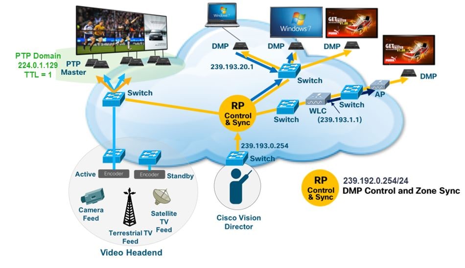
PTP for Video Wall Synchronization
NTP provides reliable clocking for your Cisco Vision network and helps ensure synchronicity between redundant servers and between the Cisco Vision Dynamic Signage Director and the DMPs. The IEEE 1588 Precision Time Protocol (PTP) is used between DMPs.
Figure 5 The Role of NTP and PTP for Synchronization
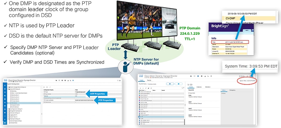
The IEEE 1588 Precision Time Protocol (PTP) is a configurable synchronization option to synchronize clocks among the DMPS driving the display of time-critical content like for video walls.
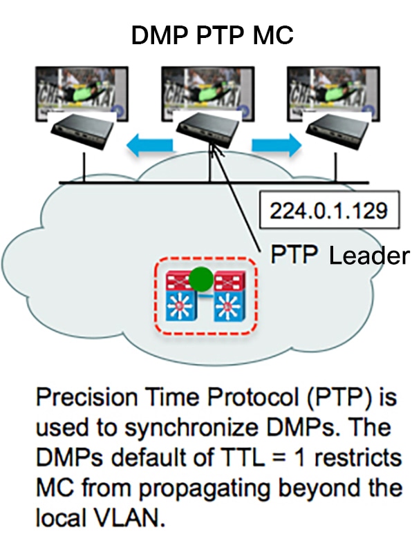
Figure 6 DMP PTP Synchronization
When using PTP, one DMP is designated as the domain leader clock. It will synchronize with a NTP reference clock and then act as the reference point for a set (subdomain only) of secondary DMP clocks. The protocol provides the means for secondary DMPs to determ
ine the path delay incurred from the leader to themselves. This time delay is then incorporated in the secondary’s time to allow for highly precise time synchronization to the leader DMP clock.
IEEE-1588 PTP uses multicast messages for communication with the following addresses:
224.0.1.129 – Default subdomain 0 (only subdomain supported)
Note: The DMPs use a TTL of 1 default, meaning PTP multicast is confined to the local subnet or VLAN. The TTL may be changed to greater than 1 to traverse a number of layer 3 hops. Careful consideration should be used when configuring TTL > 1 to traverse multiple hops due to the increased latency incurred, and the potential to exhaust the FIB database. This may negatively affect synchronization. Also, the multicast routing in the network must be configured for the PTP group addresses mentioned above.
In SDA architectures, TTL is decremented between nodes even in the same VLAN, so PTP will only function within a node or switches cascaded from a node. It is not recommended to compensate by increasing TTL since it might exhaust the multicast route table on the underlay. Given this, video walls and synchronization will only be applicable within a specific node infrastructure.
Fiber Uplinks
Note: The more common design implemented today is collapsed core, using trunk connections from the access layer back to the core, and with all layer 3 back in the core.
Access layer stack of switches are connected via 2 x 10 GE fiber cables to the core switches. The fibers should be routed via two diverse paths to avoid catastrophic fiber failure in any one fiber run. The fibers are connected to the Access stack in alternate switches to provide redundancy in case of switch failure. Small /30 subnets are used for these uplinks to provide routed EIGRP dual paths and manageability for each individual fiber link or in the case of a VSS core, Multi-chassis Etherchannel is used to bundle the fiber uplinks into a single logical uplink. In either uplink configuration, traffic is load-balanced across all links. It’s important in bandwidth planning that traffic can be handled by the remaining active links when there is a link failure.
Uni-Directional Link Detection
Uni-Directional Link Detection (UDLD) is used to detect and avoid RX/TX single fiber failures affecting the stability of the routing and switching environment. UDLD is configured on the 10 GE fiber uplinks to avoid such problems.
Spanning Tree and Protection
Spanning Tree Rapid PVST is enabled by default on many Cisco switches and provides per-VLAN spanning tree protection. It is preferred over MST since that only provides one spanning tree domain. Use RPVST or PVST+ mode on the Access stack to ensure loops from external devices are not introduced to the Layer 3 access network.
Portfast
The Spanning Tree feature portfast is configured on all access ports on the Access switch stacks to allow host ports to move quickly from Blocking to Forwarding.
BPDUGuard
Bridge Control Data Unit Guard (BPDUGuard) enabled on all access ports ensures that ports are automatically disabled if they receive BPDUs from miscabled connection to external switches which could cause Spanning Tree disruption within the access layer and potential switching loops. When BPDUs are seen on such access ports, the port is err-disabled to avoid disruption and messages appear on the NMS systems to alert Operations staff to investigate the issue.
Wireless Access
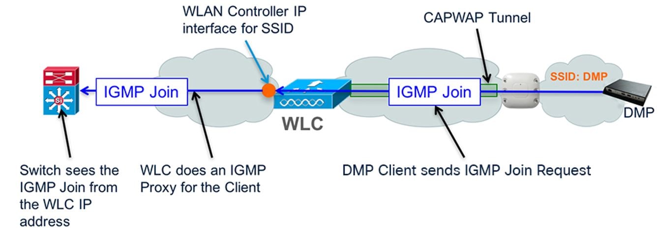
Certain models of DMPs supported Wi-Fi connectivity. For example, Series 2 DMPs and some specific hardware models in the Series 3 DMPs supported Wi-Fi. For those use cases, if content synchronization is needed, then the Wi-Fi network must support multicast to the edge. Refer to the relevant Wi-Fi design guides for further information.
Unicast control is currently supported in Cisco Vision Director releases. However, that feature does not support content synchronization.
Figure 7 Multicast over Wi-Fi Overview
Digital Media Player Topics
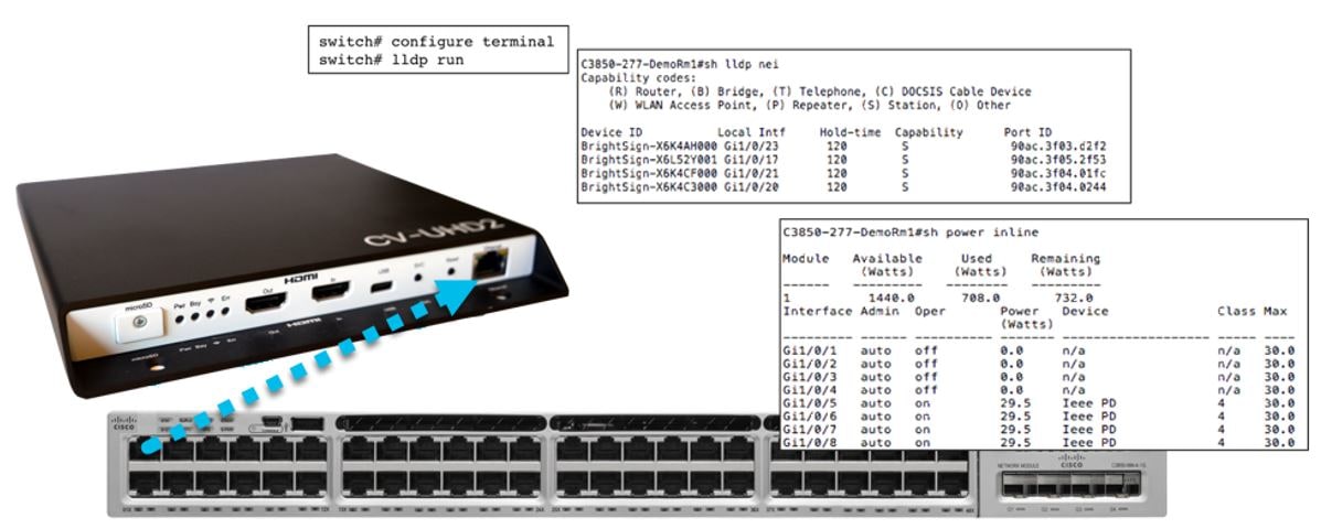
The Role of LLDP in DMP Connectivity
The Cisco Vision DMPs support standard Link Layer Discovery Protocol (LLDP). This capability allows the switch and DMP to learn about each other by exchanging LLDP messages and to negotiate 802.3at power over the Ethernet connection. Cisco Vision Dynamic Signage Director uses LLDP information for populating the switch information. This aids in troubleshooting.
Power over Ethernet
Access Layer switches should support the higher power IEEE 802.1at Power over Ethernet, also known as PoE+, which supports up to 30W per port. The new DMPs require higher power to take advantage of new capabilities. The following table shows the power requirements of the DMPs.
|
|
|
|
|
|||
|---|---|---|---|---|---|---|
|
|
|
|
|
|
|
|
|
|
|
|
|
|
|
|
|
|
|
|
|
|
|
|
Note 1 : When only 15W is available, it may appear that the DMP is partially working, but some features including display of video and HTML5 issues can occur, so powering this DMP in this mode is not supported and it should not be deployed in this fashion.
The Access Layer switches should also always be equipped with redundant as well as the highest wattage power supplies and careful consideration must be made when choosing a switch model to ensure the switch can support the required number of PoE/PoE+ ports.
Figure 8 The Role of 802.3at Power over Ethernet and LLDP
The Role of Switch Port Civic Location
IOS civic location is a collection of labels that can be configured on each switch port, and then communicated to the DMP via LLDP. One use case for civic location is jack ID, hence allowing the DMP to learn what Ethernet jack it is connected to. The DMP reports any civic location information it learns back to Cisco Vision Dynamic Signage Director, where it can be retrieved and displayed by Cisco Vision Dynamic Signage Director (Figure 9). Click Device Management > All Devices. Select a device, the bottom panel appears. Click Settings > Network tabs.

The Role of DHCP Options for DMP Auto-Registration
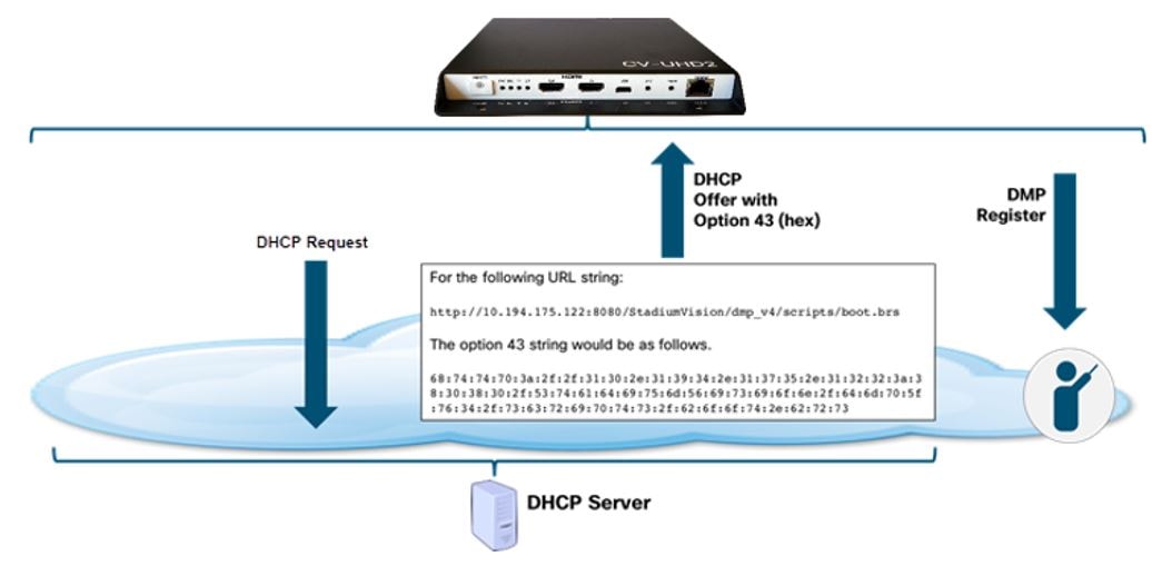
The DMP receives firmware and configuration from Cisco Vision Dynamic Signage Director. The DMP finds the Cisco Vision Dynamic Signage Director server using DHCP options (option 43). Historically, option 60 was used with early DMPs to signal the DMP for the correct option 43 content meant for it. Option 60 is no longer used or required for current DMP models.
Figure 10 DHCP and DMP Auto Registration
Configuration of DHCP Option 43 TLV String
This section highlights some details on option 43 use and format only. For full configuration details, refer to the appropriate Cisco Vision Deployment Guide for the specific Series and/or models of Digital Media Players. The guides are listed here:
https://www.cisco.com/c/en/us/support/video/stadiumvision/products-maintenance-guides-list.html
DHCP Option 43 provides a means of delivering a vendor specific URL to the DMP. Depending on the switch/IOS version, the DMP may require type-length-value (TLV) format for the option 43 data string, otherwise the “ascii” option can be used in some IOS versions. Specifically, the TLV format is constructed in the following manner:
■![]() The string is built using hex values.
The string is built using hex values.
■![]() The string begins with a hex byte of the option 43 Type (an option 43 sub-option).
The string begins with a hex byte of the option 43 Type (an option 43 sub-option).
■![]() The second hex byte is the length of the information string, or the number of ASCII characters of the string.
The second hex byte is the length of the information string, or the number of ASCII characters of the string.
■![]() Following the length value, the ascii string is typed out by using the hex byte equivalent of each character in the string.
Following the length value, the ascii string is typed out by using the hex byte equivalent of each character in the string.
■![]() The type designation is type 85 (decimal), expressed as type 55 (hex).
The type designation is type 85 (decimal), expressed as type 55 (hex).
For the following URL string, where 10.194.175.122 is the IP address of the Director server:
http://10.194.175.122:8080/CiscoVision/dmp_v4/scripts/boot.brs
The option 43 string would be as follows.
Hint: Use an ascii-to-hex conversion tool to simplify creating the hex string.
68:74:74:70:3a:2f:2f:31:30:2e:31:39:34:2e:31:37:35:2e:31:32:32:3a:38:30:38:30:2f:43:69:73:63:6f:56:69:73:69:6f:6e:2f:64:6d:70:5f:76:34:2f:73:63:72:69:70:74:73:2f:62:6f:6f:74:2e:62:72:73
Next, you place in front of this string the hex representation for <decimal type code>:<decimal number of characters in the string>
Note: In Microsoft Word, you can carefully highlight the string and then click Tools > Word Count to get the number of characters in the string.
The type code is 55 in hex and in the above URL example, there are 62 characters in the string. Decimal 62 is equal to 3E in hex.
55:3E:68:74:74:70:3a:2f:2f:31:30:2e:31:39:34:2e:31:37:35:2e:31:32:32:3a:38:30:38:30:2f:43:69:73:63:6f:56:69:73:69:6f:6e:2f:64:6d:70:5f:76:34:2f:73:63:72:69:70:74:73:2f:62:6f:6f:74:2e:62:72:73
Connecting the DMP to the Wi-Fi Network
This section does not apply to the current DMP models and is left for reference for specific older DMP models that support Wi-Fi connectivity and are deployed where there is no existing Ethernet cabling, or simply as an alternative to Ethernet network connectivity (Figure 11).
Refer to the appropriate Cisco Vision Deployment Guide for the specific Series and/or models of Media Players. The guides are listed here:
https://www.cisco.com/c/en/us/support/video/stadiumvision/products-maintenance-guides-list.html
Figure 11 Connecting the DMP to the Wi-Fi Network Overview
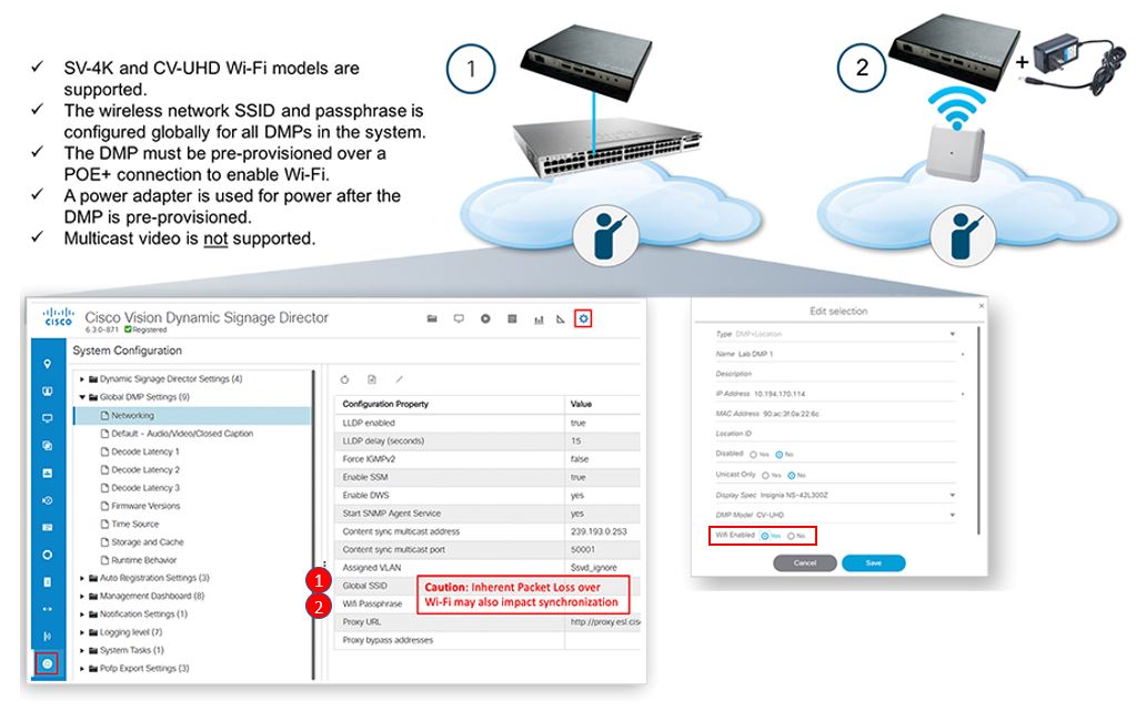
The checklist below shows the requirements and caveats for provisioning the Wi-Fi DMP models.
■![]() SV-4K and CV-UHD (part # CVUHD-WIFI-K9) are Wi-Fi connected DMPs supported in Cisco Vision Dynamic Signage Director Release 5.0 or later.
SV-4K and CV-UHD (part # CVUHD-WIFI-K9) are Wi-Fi connected DMPs supported in Cisco Vision Dynamic Signage Director Release 5.0 or later.
■![]() Support for the following Wi-Fi standards: 802.11a, 802.11b, or 802.11n.
Support for the following Wi-Fi standards: 802.11a, 802.11b, or 802.11n.
■![]() The wireless network SSID and passphrase is configured globally for all.
The wireless network SSID and passphrase is configured globally for all.
■![]() Wi-Fi-capable DMPs in the system.
Wi-Fi-capable DMPs in the system.
■![]() The SV-4K firmware automatically tries to connect with WEP (if the passphrase is of a suitable length), WPA1 or WPA2.
The SV-4K firmware automatically tries to connect with WEP (if the passphrase is of a suitable length), WPA1 or WPA2.
■![]() A Wi-Fi access point must be configured to support multicast.
A Wi-Fi access point must be configured to support multicast.
■![]() The DMP must be pre-provisioned over a POE+ connection to enable Wi-Fi.
The DMP must be pre-provisioned over a POE+ connection to enable Wi-Fi.
■![]() A DMP power adapter is used for power after the DMP is pre-provisioned.
A DMP power adapter is used for power after the DMP is pre-provisioned.
■![]() Multicast video is not supported due to bandwidth limitations and inherent packet loss over a wireless network.
Multicast video is not supported due to bandwidth limitations and inherent packet loss over a wireless network.
■![]() Due to packet loss over Wi-Fi, TV on/off multicast control messages may be lost. TV control commands like TV power on or off may not consistently work as expected.
Due to packet loss over Wi-Fi, TV on/off multicast control messages may be lost. TV control commands like TV power on or off may not consistently work as expected.
■![]() If a data feed using multicast is dropped, the DMP continues to show old data or no data if the first message is lost.
If a data feed using multicast is dropped, the DMP continues to show old data or no data if the first message is lost.
Using a DMP as an IP Multicast Source
The following two modes of streaming from the DMP are supported:
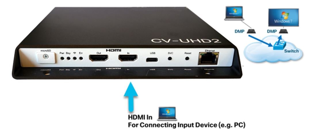
1.![]() HDMI-In streaming: Cisco Vision Dynamic Signage Solution supports streaming audio/video from a laptop or other supported device connected to the HDMI-In port on the SV-4K, CV-UHD, or CV-UHD2 media players to be played as a multicast-based channel over the wired Ethernet port.
HDMI-In streaming: Cisco Vision Dynamic Signage Solution supports streaming audio/video from a laptop or other supported device connected to the HDMI-In port on the SV-4K, CV-UHD, or CV-UHD2 media players to be played as a multicast-based channel over the wired Ethernet port.
2.![]() Display streaming: The entire video composition (without audio) on the DMP and presented on a TV connected to its HDMI-Out port will be encoded and streamed out from the DMP as a multicast-based channel over the wired ethernet port. This is useful to create a stream source that is a composition of multiple elements on the screen, for example an HTML5 page, and some other video source (or even HDMI-In video).
Display streaming: The entire video composition (without audio) on the DMP and presented on a TV connected to its HDMI-Out port will be encoded and streamed out from the DMP as a multicast-based channel over the wired ethernet port. This is useful to create a stream source that is a composition of multiple elements on the screen, for example an HTML5 page, and some other video source (or even HDMI-In video).
Note: Proper QOS DSCP classification must be set for DMP IP Multicast traffic on the network.
Figure 12 Using the DMP as an IP Multicast Source
Note: If you want to maintain privacy of channels, create a DMP-encoded channel per suite with a unique multicast address (from 239.192.20.0/24 range), and create a separate channel guide per suite. For example, if you have 10 suites—create 10 separate DMP-encoded channels with unique multicast addresses, create 10 different channel guides for each DMP-encoded channel, and assign each suite to a different channel guide.
For more information about configuring this feature, see Release 6.3: Cis co Vision Dynamic Signage Director Operations Guide.
DMP Control and Content Synchronization
Cisco Vision Dynamic Signage Director uses IP multicast to send messages to control DMPs and synchronized content. Be sure to use the value that is configured in your network for transport of Cisco Vision Dynamic Signage Director control messages. Typically, the Multicast RP used for DMP control and synchronization is on the network’s core switches. If SSM is used instead of RP, then for address usage adhere to RFC 4607.
Figure 13 Using IP Multicast for DMP Control and Content Synchronization
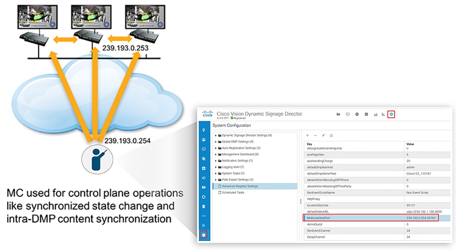
Table 2 Multicast Addresses used by the Cisco Vision Solution
Note: As of Release 6.2, only PTP domain 0 is supported. See latest Release Notes for updates.
Cisco Vision Dynamic Signage Director on the Network - Failover
For redundancy, Cisco Vision Dynamic Signage Director is installed on two virtual servers, where one of the servers operates as the primary active server and the other server operates as a secondary backup server. If a failure occurs, you can configure the backup server to become the active server, but the failover process is not automatic.
Both servers must reside in the same VLAN, have the same hardware configuration, and optimally connecting to their own switch as shown in the diagram below. HSRP should be configured to provide default gateway redundancy. Cisco Vision Dynamic Signage Director servers would typically be installed in the Data Center.
Figure 14 Cisco Vision Server Configuration Overview
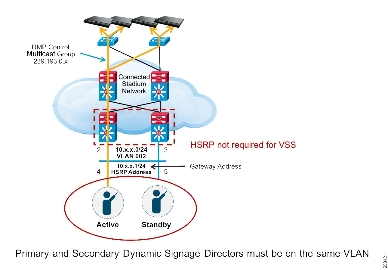
The primary and secondary servers are addressed as independent hosts with two different IP addresses on the same subnet.
The secondary server is only connected to the network to be made available as a backup to the primary should a failure occur. In addition, the secondary server can (and should) be configured to be backed up with data from the primary server on a scheduled basis so that it can be ready as a warm standby.
When the primary server fails, a manual process is used to restore the secondary server from a backup, shut down the primary server, change the secondary server’s IP address to that of the primary and then to bring the secondary server into service.
Note: Although connecting servers to the Core switches is not typically recommended. There are instances where this may be done when Data Center switches are not used in the network. The main requirement is having the Layer 2 connection between the two switches where the Cisco Vision Dynamic Signage Directors are connected.
For HSRP configuration, find the appropriate IOS software release guide for your switch.
 Feedback