- Network Architecture Role in Cisco Vision Deployments
- Network Architecture Requirements
- Multicast Role in Cisco Vision Director Solution Deployments
- Key Network Design Requirements
- Software Defined Access (SDA) Specific Guidelines
- Multicast – Mandatory Requirements (Performance-Oriented Deployments)
- Unicast – Considerations (Management-Oriented Deployments)
- Routing/Switching - Mandatory Network Design Requirements (All Deployments)
- Routing/Switching - Recommended Network Design Requirements (All Deployments)
- Quality of Service (QOS) - Mandatory Requirements (All Deployments)
- Video Headend and Video Delivery Requirements
- Cisco Vision Dynamic Signage Director Solution Requirements
- Content Transformation (CT) – Mandatory Requirements
- Content Requirements
- Cisco Vision Dynamic Signage Director (DSD) Server Requirements
- Cisco Vision Dynamic Signage Director (DSD) – Mandatory Requirements
- Cisco Vision Dynamic Signage Director (DSD) – Recommended Requirements
- Director Server Ports
- DMP Ports
- DMP – Bandwidth Considerations for WAN Deployments
Solution Operations and Deployment Requirements
Network Architecture Role in Cisco Vision Deployments
Cisco Vision Dynamic Signage Solution is a proven solution for video and content delivery in large venue deployments where high performance video display formats, low latency, resiliency, along with a comprehensive feature set for configuring a variety of TV/monitor presentation modes is needed. However, Cisco Vision Dynamic Signage Solution is also used in deployments where a smaller feature set and with less critical timing constraints suffice for the customer engagement and interactivity needs.
The underlying network is a key determinant in the type of performance and feature set that can be delivered and supported by Cisco Vision Dynamic Signage solution. This section will highlight the network salient characteristics, prevalent best practices that have proven to work in large scale and demanding deployments, and alternative network features that can support the requirements of smaller deployments that have different performance delivery profiles.
Even though Cisco Vision Dynamic Signage Solution is a network-platform agnostic solution, the cited network architecture elements called out in this chapter will reference proven Cisco and Meraki network architectures and features. References to product family names, like Catalyst or Nexus, are meant to be illustrative and not prescriptive. It is more important to follow the relevant requirements that correspond to the scale/needs of the deployment. For convenience, these deployments will be referenced as performance-oriented and management-oriented. This categorization is not indicative of size of deployment or range of features, since scalability from single, large venue to large distributed deployments can be accommodated from the same Cisco Vision product.
In the sections that follow, requirements will be categorized as Mandatory or Recommended. Mandatory requirements are those which must be followed in the design. The Recommended requirements align the deployment with proven best practices and delivery of highest performance of the solution’s available feature. Deviation from these guidelines may impact solution performance or its supported design attributes.
Network Architecture Requirements
Cisco’s Borderless Network architecture, with some customization, provides the best practice blueprint for building a scalable, tiered, hierarchical, and modular design including collapsed core/distribution and access layers that is suited to large venue deployments of Cisco Vision Director.
The architecture modularizes functions into separate blocks which are dual-homed into a redundant, collapsed core/distribution pair of switches (Figure 1).
Figure 1 Cisco Vision Network Topology
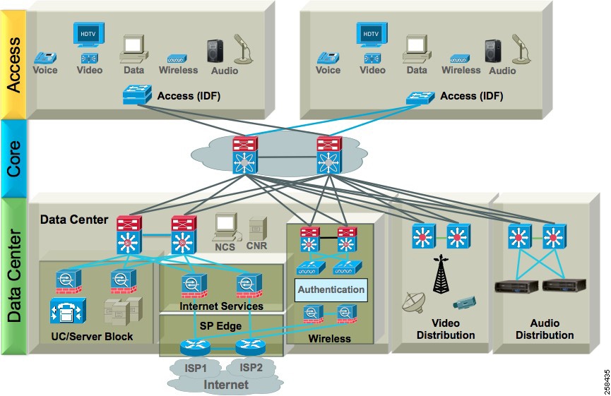
The Core layer of the network provides the high-speed, and redundant switching and aggregation of Access Layer switches including those used in the Service blocks. Building (aggregation) blocks provide flexibility during changes and upgrades.
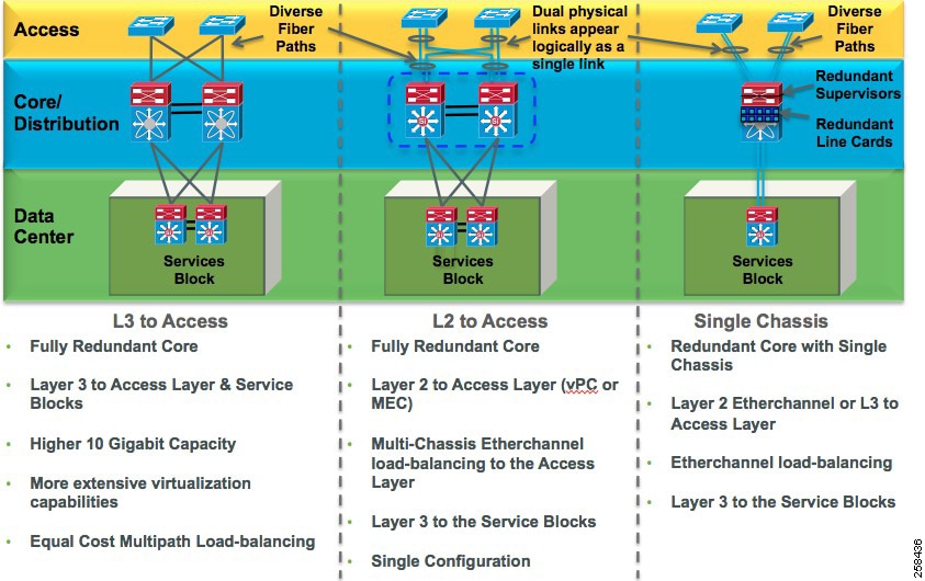
The attributes of the core designs are highlighted in the graphics above. This design can be typically implemented with Cisco Nexus or Catalyst switches or with Cisco Meraki switches.
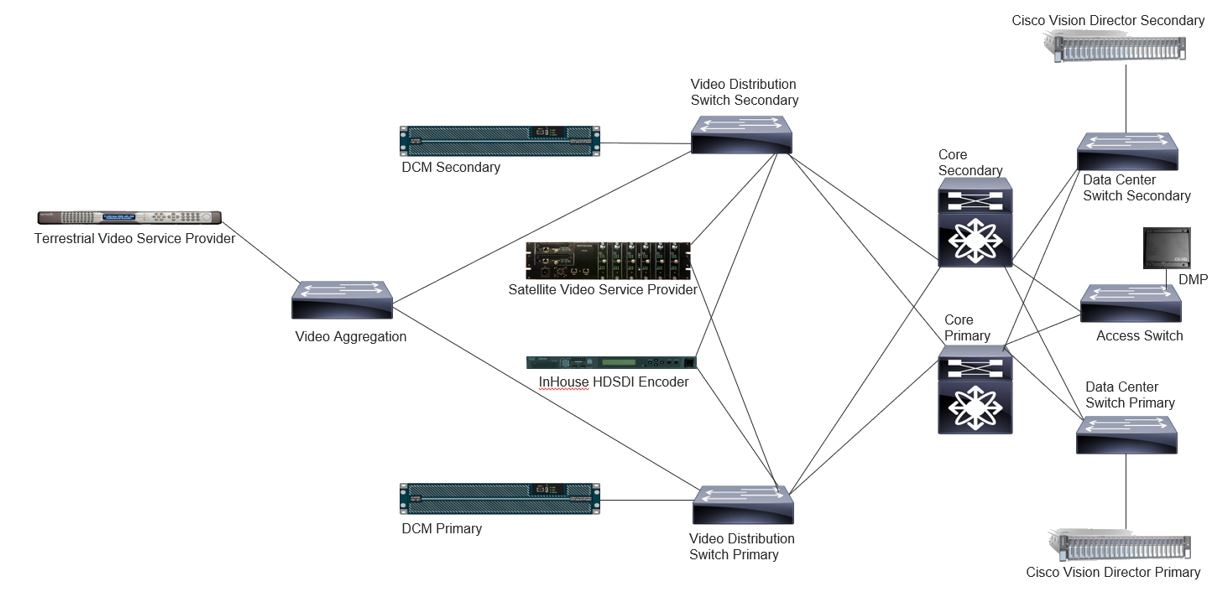
The collapsed core architecture is far more prevalent. The full Cisco Vision Director deployment in a Connected Stadium scenario is represented in Figure 3.
Figure 3 Architecture for Connected Stadium
Cisco Software-Defined Access (SDA) as part of the Cisco Digital Network Architecture is supported for Cisco Dynamic Signage Director deployments.
Figure 4 SDA Architecture with Cisco Vision Dynamic Signage Director
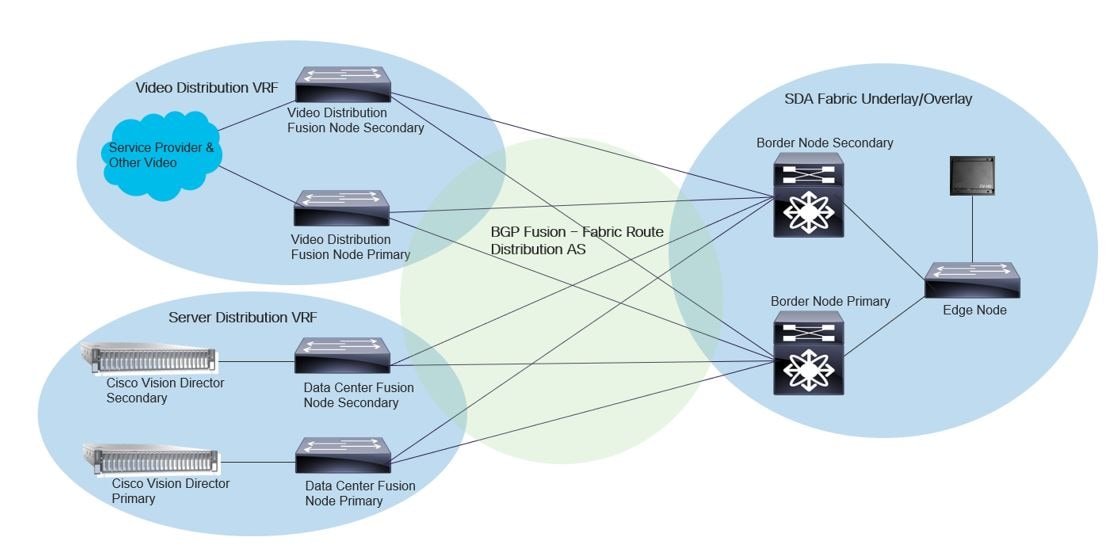
See Software Defined Access (SDA) Specific Guidelines for other relevant requirements for this architecture.
Note: Mandatory requirements cited in this document must be followed in the design. The Recommended requirements align the deployment with proven best practices. Deviation from these guidelines may impact solution performance or its supported design attributes.
Multicast Role in Cisco Vision Director Solution Deployments
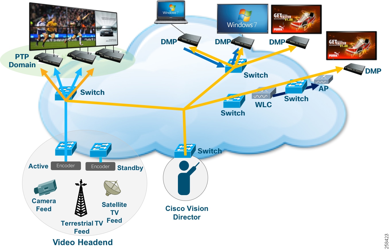
When Cisco Vision Dynamic Signage Solution is deployed in environments that require the highest scale, fastest performance, and full range of features, it requires IP multicast for the following functions:
■![]() DMP control and zone-based content synchronization.
DMP control and zone-based content synchronization.
■![]() Precision Time Protocol (PTP) for DMP-to-DMP synchronization.
Precision Time Protocol (PTP) for DMP-to-DMP synchronization.
■![]() Encode and transmit IP multicast - The DMPs may take an HDMI input, or their own screen rendering, and provide an IP multicast stream source on the network.
Encode and transmit IP multicast - The DMPs may take an HDMI input, or their own screen rendering, and provide an IP multicast stream source on the network.
■![]() Joining multicast video channels coming out from the video headend.
Joining multicast video channels coming out from the video headend.
Figure 5 IP Multicast Overview
In third-party networks that do not support multicast (e.g., Cisco Meraki WAN), unicast configurations can be used from the Cisco Vision Dynamic Signage Director to direct DMPs to video sources.
Since multicast implementations, based on type of network equipment in use, can have several variations based on the level of features that are supported, the following section will highlight the key attributes. Find a more detailed review of the multicast design considerations in different operation scenarios in the Deployment and Requirements - Expanded Topics.
Key Network Design Requirements
Software Defined Access (SDA) Specific Guidelines
These guidelines are specific to SDA, in addition to other Cisco Vision Solution network guidelines.
1.![]() PTP has been tested in two methods with SDA/DNAC and the Cisco Vision Solution.
PTP has been tested in two methods with SDA/DNAC and the Cisco Vision Solution.
a.![]() PTP TTL (time to live) set to 1 (system default).
PTP TTL (time to live) set to 1 (system default).
With a PTP TTL set to 1, DMP synchronization will not function outside a single switch stack due to TTL being decremented across the VXLAN tunnel. All DMPs that require content synchronization, such as video walls, must be on the same switch stack.
b.![]() PTP TTL set to 4.
PTP TTL set to 4.
With a PTP TTL set to 4, DMP synchronization will function across the entire VLAN.
PTP TTL set to 4 is the preferred configuration. This may not be possible due to SDA limitations.
2.![]() VLAN - Best practices for the Cisco Vision Director Solution is to have no more than 500 DMPs per VLAN. This is due to the tremendous amount of PTP traffic generated from DMPs on the VLAN.
VLAN - Best practices for the Cisco Vision Director Solution is to have no more than 500 DMPs per VLAN. This is due to the tremendous amount of PTP traffic generated from DMPs on the VLAN.
a.![]() If PTP TTL is set to 1, then one large VLAN per site may be used because the PTP traffic is isolated per switch stack. Deviation from the known best practice of no more than 500 DMPs per VLAN has not been tested.
If PTP TTL is set to 1, then one large VLAN per site may be used because the PTP traffic is isolated per switch stack. Deviation from the known best practice of no more than 500 DMPs per VLAN has not been tested.
b.![]() If PTP TTL is set to 4, with synchronization on a per VLAN basis, the 500 DMP limit per VLAN should be adhered to. However, even though setting PTP to 4 is preferred for scalability, there may be practical hardware constraints related to SDA’s architecture ability to accommodate a large number of potential multicast routes in the SDA fabric that should be considered.
If PTP TTL is set to 4, with synchronization on a per VLAN basis, the 500 DMP limit per VLAN should be adhered to. However, even though setting PTP to 4 is preferred for scalability, there may be practical hardware constraints related to SDA’s architecture ability to accommodate a large number of potential multicast routes in the SDA fabric that should be considered.
3.![]() QOS Video Requirements - QOS must be implemented throughout the fabric. Video traffic and DSD control traffic must be in a priority queue. All other traffic other than Voice must not take precedence in the fabric. QOS may be otherwise implemented according to SDA/DNAC (digital network architecture center) best practices.
QOS Video Requirements - QOS must be implemented throughout the fabric. Video traffic and DSD control traffic must be in a priority queue. All other traffic other than Voice must not take precedence in the fabric. QOS may be otherwise implemented according to SDA/DNAC (digital network architecture center) best practices.
4.![]() Video Distribution Switch (VDS) Requirements
Video Distribution Switch (VDS) Requirements
a.![]() Border Gateway Protocol (BGP) – VDS switches are considered “Fusion Nodes” in the SDA/DNAC architecture. Route protocol must be External Border Gateway Protocol (EBGP). Virtual Routing and Forwarding (VRF) for the overlay must be utilized and match that of the overlay fabric of SDA.
Border Gateway Protocol (BGP) – VDS switches are considered “Fusion Nodes” in the SDA/DNAC architecture. Route protocol must be External Border Gateway Protocol (EBGP). Virtual Routing and Forwarding (VRF) for the overlay must be utilized and match that of the overlay fabric of SDA.
The significant delta between standard design and SDA is the addition of BGP and tuned timers to facilitate quicker failover.
Each VDS switch must peer with each SDA Border Node. Underlay global VRF peering may or may not be used.
A network statement or redistribution of connection may be used for the Cisco Vision VRF.
b.![]() Source-specific multicast (SSM) must be configured on each VDS Switch.
Source-specific multicast (SSM) must be configured on each VDS Switch.
c.![]() External Fabric Rendezvous Point (RP) any-source multicast (ASM) - VDS Fusion Nodes must be configured with an external PriorityCast RP address and associated access control list (ACL).
External Fabric Rendezvous Point (RP) any-source multicast (ASM) - VDS Fusion Nodes must be configured with an external PriorityCast RP address and associated access control list (ACL).
5.![]() Server Switch / Datacenter Gateway Requirements
Server Switch / Datacenter Gateway Requirements
a.![]() BGP & VRF Route Leaking - The Server Switch is considered a “Fusion Node” in the SDA/DNAC architecture. Route protocol must be EBGP. VRF for the overlay must be utilized and matching that of the overlay fabric of SDA.
BGP & VRF Route Leaking - The Server Switch is considered a “Fusion Node” in the SDA/DNAC architecture. Route protocol must be EBGP. VRF for the overlay must be utilized and matching that of the overlay fabric of SDA.
VRF for the underlay must also be used for the purpose of route distribution between underlay where network services such as Cisco Vision DSD, NTP, and DHCP may be redistributed from the underlay or other network into the Cisco Vision VRF.
The significant delta between standard design and SDA is the addition of BGP and tuned timers to facilitate quicker failover, as well as route leaking between VRFs.
The Server switch must peer with each SDA Border Node.
A network statement or redistribution of connection may be used for the Cisco Vision VRF or underlay.
No ASM is supported on the Server switches.
b.![]() SSM must be configured on the Server switch.
SSM must be configured on the Server switch.
a.![]() External Fabric RP (ASM) - SDA Edge Node must be configured with an external PriorityCast RP address and associated ACL.
External Fabric RP (ASM) - SDA Edge Node must be configured with an external PriorityCast RP address and associated ACL.
b.![]() LLDP must be configured on each edge node to facilitate power negotiation.
LLDP must be configured on each edge node to facilitate power negotiation.
c.![]() SSM must be configured on the edge nodes.
SSM must be configured on the edge nodes.
a.![]() External Fabric RP (ASM) - SDA Edge Node must be configured with an external PriorityCast RP address and associated ACL.
External Fabric RP (ASM) - SDA Edge Node must be configured with an external PriorityCast RP address and associated ACL.
b.![]() BGP - VDS switches are considered “Fusion Nodes” in the SDA/DNAC architecture. Route protocol must be EBGP. VRF for the overlay must be utilized and matching that of the overlay fabric of SDA.
BGP - VDS switches are considered “Fusion Nodes” in the SDA/DNAC architecture. Route protocol must be EBGP. VRF for the overlay must be utilized and matching that of the overlay fabric of SDA.
The significant delta between standard design and SDA is the addition of BGP and tuned timers to facilitate quicker failover.
Each VDS switch must peer with each SDA Border Node. Underlay global VRF peering may or may not be used.
A network statement or redistribution of connected may be used for the Cisco Vision VRF.
Multicast – Mandatory Requirements (Performance-Oriented Deployments)
The latest releases of Cisco Vision Dynamic Signage Solution support SSM and Internet Group Management Protocol (IGMP)v3 architectures. SSM allows for efficient data delivery in one-to-many communications. This means that Anycast and Prioritycast protocols referenced in the Mandatory listing are no longer required, even though the general design remains. If the network has implemented IGMPv2 [Protocol Independent Multicast (PIM) sparse and dense mode] then RP will be required for the Anycast and Prioritycast protocols to allow discovery and joining of multicast groups to their destinations.
Here are the MANDATORY requirements:
1.![]() Implement PIM Sparse mode per VLAN Switch Virtual Interface (SVI) or routed interface must be used for the distribution or intermediate relay of Cisco Vision Dynamic Signage Director or IPTV Video Headend equipment traffic.
Implement PIM Sparse mode per VLAN Switch Virtual Interface (SVI) or routed interface must be used for the distribution or intermediate relay of Cisco Vision Dynamic Signage Director or IPTV Video Headend equipment traffic.
2.![]() IGMPv2 on every DMP VLAN SVI should be implemented. IGMPV3 is optional but is mandatory for SSM deployments.
IGMPv2 on every DMP VLAN SVI should be implemented. IGMPV3 is optional but is mandatory for SSM deployments.
3.![]() Enable IP Multicast in the Global Routing Table, VRF and/or virtual device context (VDC) where Cisco DMP, Cisco Vision Dynamic Signage Director and IP Multicast Video traffic will traverse.
Enable IP Multicast in the Global Routing Table, VRF and/or virtual device context (VDC) where Cisco DMP, Cisco Vision Dynamic Signage Director and IP Multicast Video traffic will traverse.
4.![]() Implement SSM for DMP control information. If not available, Anycast RP should be implemented in the Core/Spine switches for the Cisco Vision Dynamic Signage Director IP Multicast control information and the network Core/Spine switches must be the root of the Anycast RP tree. In addition, Multicast Source Discovery Protocol (MSDP) must be used to exchange source or group information between the Anycast RPs of any non VSS core/spine pair.
Implement SSM for DMP control information. If not available, Anycast RP should be implemented in the Core/Spine switches for the Cisco Vision Dynamic Signage Director IP Multicast control information and the network Core/Spine switches must be the root of the Anycast RP tree. In addition, Multicast Source Discovery Protocol (MSDP) must be used to exchange source or group information between the Anycast RPs of any non VSS core/spine pair.
5.![]() Implement SSM for video sourcing connection (Prioritycast). If not available, Prioritycast RP must be implemented in the IPTV Video Headend Video Distribution Switches, with PIM RP-Mapping configuration on all L3 networks and devices between the Cisco DMP VLANS, originating multicast video, Cisco Vision Dynamic Signage Director or other critical traffic.
Implement SSM for video sourcing connection (Prioritycast). If not available, Prioritycast RP must be implemented in the IPTV Video Headend Video Distribution Switches, with PIM RP-Mapping configuration on all L3 networks and devices between the Cisco DMP VLANS, originating multicast video, Cisco Vision Dynamic Signage Director or other critical traffic.
6.![]() Network support for IEEE 1588 Precision Time Protocol on every DMP VLAN Switch Virtual Interface.
Network support for IEEE 1588 Precision Time Protocol on every DMP VLAN Switch Virtual Interface.
7.![]() The network Multicast Routing Information Base and Multicast Forwarding Information Base must support the total sum or greater of Multicast streams in the Intranetwork including Data, Video and PTP multicast.
The network Multicast Routing Information Base and Multicast Forwarding Information Base must support the total sum or greater of Multicast streams in the Intranetwork including Data, Video and PTP multicast.
Unicast – Considerations (Management-Oriented Deployments)
In networks that do not have the required multicast features, or where some DMPs are deployed at locations that cannot be reached via multicast, unicast settings in Cisco Vision Director allow remote control and operation of DMPs and the following restrictions should be noted:
1.![]() State synchronization across multiple DMPs – unicast state changes cannot provide the same synchronization that multicast messaging offers.
State synchronization across multiple DMPs – unicast state changes cannot provide the same synchronization that multicast messaging offers.
2.![]() Zone-based video wall synchronization is not supported.
Zone-based video wall synchronization is not supported.
3.![]() Certain data integration with external sources that are normally done via multicast have to be implemented in a work-around fashion.
Certain data integration with external sources that are normally done via multicast have to be implemented in a work-around fashion.
Routing/Switching - Mandatory Network Design Requirements (All Deployments)
1.![]() Hierarchical model consisting of Core, Distribution and Access Layer, or a Collapsed Core model consisting of Spine and Leaf topology.
Hierarchical model consisting of Core, Distribution and Access Layer, or a Collapsed Core model consisting of Spine and Leaf topology.
2.![]() Power over Ethernet compliant to IEEE 802.1at (POE+ 30 watts per DMP interface for indicated models) provided by the network Access layer/Leaf switches.
Power over Ethernet compliant to IEEE 802.1at (POE+ 30 watts per DMP interface for indicated models) provided by the network Access layer/Leaf switches.
The following table shows the power requirements of the Series 2-4 DMPs:
|
|
|
|
|
|||
|---|---|---|---|---|---|---|
|
|
|
|
|
|
|
|
|
|
|
|
|
|
|
|
|
|
|
|
|
|
|
|
Note 1 : When only 15W is available, it may appear that the DMP is partially working, but some features including display of video and HTML5 issues can occur Powering the DMP in this mode is not supported and it should not be deployed in this fashion.
3.![]() Use redundant power supplies at the network Access layer/Leaf switches capable of supporting all connected DMPs.
Use redundant power supplies at the network Access layer/Leaf switches capable of supporting all connected DMPs.
4.![]() Implement IEEE 802.1ab (LLDP) on all Access layer/Leaf switches physically connected to each DMP that requires 30 watts (e.g., UHD and UHD2 models).
Implement IEEE 802.1ab (LLDP) on all Access layer/Leaf switches physically connected to each DMP that requires 30 watts (e.g., UHD and UHD2 models).
5.![]() Use unique IP DHCP scopes, providing infinite leases using option 43, for each Cisco DMP VLAN. (DHCP option 60 is optional).
Use unique IP DHCP scopes, providing infinite leases using option 43, for each Cisco DMP VLAN. (DHCP option 60 is optional).
6.![]() Use a preserved state database with synchronization between redundant DHCP servers for each Cisco DMP VLAN.
Use a preserved state database with synchronization between redundant DHCP servers for each Cisco DMP VLAN.
7.![]() Use Spanning Tree Portfast or equivalent on all host access interfaces.
Use Spanning Tree Portfast or equivalent on all host access interfaces.
8.![]() BPDU Guard or equivalent on all host access interfaces.
BPDU Guard or equivalent on all host access interfaces.
9.![]() Use VLAN pruning on all trunk interfaces.
Use VLAN pruning on all trunk interfaces.
10.![]() Use 802.1w Rapid Spanning Tree on all Intra-network trunk interfaces.
Use 802.1w Rapid Spanning Tree on all Intra-network trunk interfaces.
11.![]() Do not exceed 500 DMPs per VLAN.
Do not exceed 500 DMPs per VLAN.
Use no security measures or mechanisms which may prevent a DMP from obtaining and maintaining a lease in the current provisioned VLAN. These may reallocate provisioned VLANS, intercept or respond to the DHCP ARP verification process or other security technologies, which may prevent access to the network in a timely manner or require authentication.
Use no traffic filtering device, or security or provisioning device, in any part of the end-to-end L2/L3 network path between Cisco DMP VLANS, IPTV Video Headend equipment, Cisco Vision Dynamic Signage Director and/or other critical traffic that would disrupt the normal flow of data traffic between the mentioned devices.
In SDA Architectures, video walls and synchronization are only applicable within a specific node infrastructure. This is because TTL is decremented between nodes and increasing PTP TTL is not recommended as a method to compensate for it.
Routing/Switching - Recommended Network Design Requirements (All Deployments)
1.![]() At least 4 x 10-Gigabit uplinks between each Core or Spine switch.
At least 4 x 10-Gigabit uplinks between each Core or Spine switch.
2.![]() Cisco Catalyst switches for the network Access layer/Leaf switches.
Cisco Catalyst switches for the network Access layer/Leaf switches.
3.![]() Cisco Catalyst or Nexus switches (redundant configuration) for the network Core/Spine switches.
Cisco Catalyst or Nexus switches (redundant configuration) for the network Core/Spine switches.
4.![]() Use virtual port channel (VPC), VSS or similar technologies in the network Core/Spine switches.
Use virtual port channel (VPC), VSS or similar technologies in the network Core/Spine switches.
5.![]() Use rapid per VLAN spanning tree (RPVST) on Intra-network trunk interfaces.
Use rapid per VLAN spanning tree (RPVST) on Intra-network trunk interfaces.
6.![]() Two 10 Gigabit Ethernet links per network Access layer/Leaf and Distribution layer switches, with each link connected to an adjacent hierarchical switch.
Two 10 Gigabit Ethernet links per network Access layer/Leaf and Distribution layer switches, with each link connected to an adjacent hierarchical switch.
7.![]() Use fiber-based uplinks between the network Access layer/Leaf and Distribution layer to both Core/Spine switches.
Use fiber-based uplinks between the network Access layer/Leaf and Distribution layer to both Core/Spine switches.
8.![]() Do not cascade network Access layer/Leaf switches.
Do not cascade network Access layer/Leaf switches.
9.![]() Enhanced Interior Gateway Routing Protocol (EIGRP) is recommended for unicast routing in two-tier networks. Note the following exceptions:
Enhanced Interior Gateway Routing Protocol (EIGRP) is recommended for unicast routing in two-tier networks. Note the following exceptions:
a.![]() Network may use open shortest path first (OSPF) protocol. OSPF is hierarchical and typically used for three-tiered network designs.
Network may use open shortest path first (OSPF) protocol. OSPF is hierarchical and typically used for three-tiered network designs.
b.![]() Network may use border gateway protocol (BGP) for connectivity to fusion nodes in SDA architectures.
Network may use border gateway protocol (BGP) for connectivity to fusion nodes in SDA architectures.
10.![]() Implement default gateway redundancy. Use Gateway Load Balancing Protocol (GLBP) which provides for router load balancing as well as redundancy among leader and standby routers, or, for active/standby router redundancy only, implement either Virtual Router Redundancy Protocol (VRRP) or Hot Standby Router Protocol (HSRP).
Implement default gateway redundancy. Use Gateway Load Balancing Protocol (GLBP) which provides for router load balancing as well as redundancy among leader and standby routers, or, for active/standby router redundancy only, implement either Virtual Router Redundancy Protocol (VRRP) or Hot Standby Router Protocol (HSRP).
11.![]() Use dual redundant external Internet access for external content integration to sources beyond the Intra-network.
Use dual redundant external Internet access for external content integration to sources beyond the Intra-network.
12.![]() Use a separate Cisco DMP VLAN per intermediate distribution frame (IDF) switch stack.
Use a separate Cisco DMP VLAN per intermediate distribution frame (IDF) switch stack.
Quality of Service (QOS) - Mandatory Requirements (All Deployments)
In Cisco Vision, end-to-end QOS support is needed for delivery of video traffic. Video traffic is classified, marked and policed as it enters the network. This traffic is then queued according to administratively configured priority as it is carried through the network. This purposeful handling of the traffic guarantees that the network meets the performance requirements of video delivered for display on DMP connected monitors, whether it is sourced from the video headend, or from a DMP that is used as an encoded source on the network. Here are the requirements:
2.![]() Use Differentiated Services Code Points (DSCP) and Per-Hop Behaviors (PHB).
Use Differentiated Services Code Points (DSCP) and Per-Hop Behaviors (PHB).
3.![]() Implement traffic classification with appropriate DSCP marking applied at ingress to the network for all IP Multicast video, Cisco Vision Dynamic Signage Director data traffic, and other critical traffic.
Implement traffic classification with appropriate DSCP marking applied at ingress to the network for all IP Multicast video, Cisco Vision Dynamic Signage Director data traffic, and other critical traffic.
4.![]() Use DSCP classification of CS5 for all Cisco DMP IP Multicast, IP Multicast Video, and Cisco Vision Dynamic Signage Director IP Multicast traffic.
Use DSCP classification of CS5 for all Cisco DMP IP Multicast, IP Multicast Video, and Cisco Vision Dynamic Signage Director IP Multicast traffic.
5.![]() Implement an egress queue policy-map which includes a priority queue that reserves 15% of total 10-Gigabit uplink interface bandwidth for IP Multicast Video traffic on all interfaces between the Cisco DMP VLANS, IPTV Video Headend equipment, Cisco Vision Dynamic Signage Director, and/or other critical traffic.
Implement an egress queue policy-map which includes a priority queue that reserves 15% of total 10-Gigabit uplink interface bandwidth for IP Multicast Video traffic on all interfaces between the Cisco DMP VLANS, IPTV Video Headend equipment, Cisco Vision Dynamic Signage Director, and/or other critical traffic.
6.![]() Use QOS trust boundaries on all Intra-network interfaces between the DMP VLANS and the originating multicast video, Cisco Vision Dynamic Signage Director, or other critical traffic.
Use QOS trust boundaries on all Intra-network interfaces between the DMP VLANS and the originating multicast video, Cisco Vision Dynamic Signage Director, or other critical traffic.
For additional design information, refer to the Enterprise QoS Solution Reference Network Design Guide.
Video Headend and Video Delivery Requirements
Follow these requirements for the transport and delivery of IP video architecture and design. Areas covered within the section include:
■![]() Video Transport (VT) and Delivery
Video Transport (VT) and Delivery
Video Sources (VS) – Mandatory Requirements
1.![]() For any In-House generated video, Terrestrial/Satellite/Over The Air video service providers and all other third-party video service providers, ensure the network supports all customer-selected UHD, HD and/or SD programs as provisioned in total aggregate throughput by the end customer and/or their authorized agents for input, and end-to-end in the Cisco Vision Dynamic Signage Director solution.
For any In-House generated video, Terrestrial/Satellite/Over The Air video service providers and all other third-party video service providers, ensure the network supports all customer-selected UHD, HD and/or SD programs as provisioned in total aggregate throughput by the end customer and/or their authorized agents for input, and end-to-end in the Cisco Vision Dynamic Signage Director solution.
2.![]() Ensure the IPTV Video Headend encapsulates all encoded MPEG-2, MPEG-4, and MPEG-H IPTV traffic in ISO 13818 MPEG-TS (transport streams) for transport throughout the network.
Ensure the IPTV Video Headend encapsulates all encoded MPEG-2, MPEG-4, and MPEG-H IPTV traffic in ISO 13818 MPEG-TS (transport streams) for transport throughout the network.
3.![]() IPTV Video Headend must have redundant network connections between the video distributions switches and the Core/Spine switches.
IPTV Video Headend must have redundant network connections between the video distributions switches and the Core/Spine switches.
4.![]() Network infrastructure incorporates supported multicast routing for distribution of all IPTV channels.
Network infrastructure incorporates supported multicast routing for distribution of all IPTV channels.
5.![]() For IGMPV2 implementations - IPTV Video Headend Video Distributions Switches must be the root of the Prioritycast RP Tree.
For IGMPV2 implementations - IPTV Video Headend Video Distributions Switches must be the root of the Prioritycast RP Tree.
6.![]() IPTV Video Headend Video Distribution Switches must not be used as access switches for DMPs, except for the purpose of monitoring video traffic.
IPTV Video Headend Video Distribution Switches must not be used as access switches for DMPs, except for the purpose of monitoring video traffic.
7.![]() IP Multicast Video must not be encrypted with any encryption algorithm except those explicitly outlined as supported in the associated Cisco Vision Dynamic Signage Director documentation.
IP Multicast Video must not be encrypted with any encryption algorithm except those explicitly outlined as supported in the associated Cisco Vision Dynamic Signage Director documentation.
8.![]() IP Multicast Video Transport Streams must be received by DMPs as Single Program Transport Streams.
IP Multicast Video Transport Streams must be received by DMPs as Single Program Transport Streams.
9.![]() Locally played content must be encoded using a constant bit rate for use in video wall applications.
Locally played content must be encoded using a constant bit rate for use in video wall applications.
10.![]() Ensure all video to be used in a video wall application complies with a 40 ms PCR interval and +/- 500 ms jitter/accuracy.
Ensure all video to be used in a video wall application complies with a 40 ms PCR interval and +/- 500 ms jitter/accuracy.
Video Sources (VS) – Recommended Requirements
1.![]() For IGMPV2 implementations – if the IPTV Video Headend is implemented with a primary and redundant Video Multiplexer, then Prioritycast RP should be used for Redundancy.
For IGMPV2 implementations – if the IPTV Video Headend is implemented with a primary and redundant Video Multiplexer, then Prioritycast RP should be used for Redundancy.
2.![]() IP Multicast Video Transport Streams bit rate should be 10-25 mbps per HD stream and 25-35 mbps per UHD stream.
IP Multicast Video Transport Streams bit rate should be 10-25 mbps per HD stream and 25-35 mbps per UHD stream.
3.![]() IPTV Video Headend should include a primary and redundant Video Distribution Switch (VDS).
IPTV Video Headend should include a primary and redundant Video Distribution Switch (VDS).
Video Encoding (VE) – Mandatory Requirements
1.![]() IPTV Video Headend must support MPEG-2, MPEG-4 or high efficiency video coding (HEVC) internet protocol television (IPTV) traffic in ISO 13818 MPEG-TS encapsulated in UDP IP or RTP IP Multicast frames/packets.
IPTV Video Headend must support MPEG-2, MPEG-4 or high efficiency video coding (HEVC) internet protocol television (IPTV) traffic in ISO 13818 MPEG-TS encapsulated in UDP IP or RTP IP Multicast frames/packets.
2.![]() IPTV Video Headend must support the encoding of uncompressed HD-SDI In-House video sources as MPEG-2, MPEG-4 or HEVC IPTV transport streams encapsulated in IP Multicast frames/packets.
IPTV Video Headend must support the encoding of uncompressed HD-SDI In-House video sources as MPEG-2, MPEG-4 or HEVC IPTV transport streams encapsulated in IP Multicast frames/packets.
Video Encoding (VE) – Recommended Requirements
1.![]() Employ Cisco-qualified encoders in the IPTV Video Headend to inter-operate with the Cisco Vision Dynamic Signage Director solution.
Employ Cisco-qualified encoders in the IPTV Video Headend to inter-operate with the Cisco Vision Dynamic Signage Director solution.
2.![]() Use standards-based MPEG multiplexer where needed to groom the stream in some supported method or to separate Multiple Program Transport Stream (MPTS) to Single Program Transport Stream (SPTS).
Use standards-based MPEG multiplexer where needed to groom the stream in some supported method or to separate Multiple Program Transport Stream (MPTS) to Single Program Transport Stream (SPTS).
Video Delivery (VD) – Mandatory Requirements
1.![]() Use a dedicated physical 1:1 connection between each video display and each Cisco DMP via an HDMI cable to deliver audio and video programming to the video display.
Use a dedicated physical 1:1 connection between each video display and each Cisco DMP via an HDMI cable to deliver audio and video programming to the video display.
2.![]() Use a dedicated physical 1:1 connection between each video display and each Cisco DMP via an RS-232 cable to remotely control the video display with RS-232 codes.
Use a dedicated physical 1:1 connection between each video display and each Cisco DMP via an RS-232 cable to remotely control the video display with RS-232 codes.
3.![]() Customer must determine correct RS232 polarity pinout between each Cisco DMP and each video display.
Customer must determine correct RS232 polarity pinout between each Cisco DMP and each video display.
4.![]() Ensure that the required RS232 control codes for each video display model used is available.
Ensure that the required RS232 control codes for each video display model used is available.
5.![]() Any third-party control application must use Cisco’s proprietary control API for all remote-control functions.
Any third-party control application must use Cisco’s proprietary control API for all remote-control functions.
6.![]() Customer must provide all physical wiring and adaptors for the mounting and interconnections of the Cisco DMP and the video display.
Customer must provide all physical wiring and adaptors for the mounting and interconnections of the Cisco DMP and the video display.
7.![]() Provide for secure mounting of Cisco DMP, video display and all associated cabling between DMP and video display, as well as DMP and the access switch.
Provide for secure mounting of Cisco DMP, video display and all associated cabling between DMP and video display, as well as DMP and the access switch.
Video Delivery (VD) – Recommended Requirements
1.![]() Connect the included external infrared receiver to each Cisco DMP for remote control by an IR control device.
Connect the included external infrared receiver to each Cisco DMP for remote control by an IR control device.
Cisco Vision Dynamic Signage Director Solution Requirements
The requirements captured within this section are generally derived from business requirements around the operation and maintenance of the Cisco Vision Dynamic Signage Director solution, including:
■![]() Cisco Vision Dynamic Signage Director (DSD)
Cisco Vision Dynamic Signage Director (DSD)
Content Transformation (CT) – Mandatory Requirements
1.![]() HDMI DMP Pass Through must utilize an HDCP-compliant device.
HDMI DMP Pass Through must utilize an HDCP-compliant device.
2.![]() HDMI DMP Encoding input must not contain HDCP Copy Protection.
HDMI DMP Encoding input must not contain HDCP Copy Protection.
3.![]() Locally produced or third-party content may include, static image files, video files. MPEG transport streams and codecs must be provided in a format supported natively by the Cisco Vision Dynamic Signage Director solution.
Locally produced or third-party content may include, static image files, video files. MPEG transport streams and codecs must be provided in a format supported natively by the Cisco Vision Dynamic Signage Director solution.
4.![]() Do not use DMP-destined file content that exceeds 4GB in file size.
Do not use DMP-destined file content that exceeds 4GB in file size.
5.![]() Locally played content must be encoded using a constant bit rate for use in video wall applications.
Locally played content must be encoded using a constant bit rate for use in video wall applications.
6.![]() Ensure all video to be used in a video wall application complies with a 40ms PCR interval and is +/- 500ms jitter/accuracy. Video walls are considered in spec if their frames are +/- 1 frame from each other. Currently, it is recommended not to exceed 16 screens in a single video wall. Note, sync tolerance is subjective.
Ensure all video to be used in a video wall application complies with a 40ms PCR interval and is +/- 500ms jitter/accuracy. Video walls are considered in spec if their frames are +/- 1 frame from each other. Currently, it is recommended not to exceed 16 screens in a single video wall. Note, sync tolerance is subjective.
7.![]() Locally produced or third-party external content data sources which may include, XML, JSON, SQL, GSIS, Daktronix, OES, ATOM and RSS and must be provided in a format as specified by current product documentation.
Locally produced or third-party external content data sources which may include, XML, JSON, SQL, GSIS, Daktronix, OES, ATOM and RSS and must be provided in a format as specified by current product documentation.
8.![]() Locally produced or third-party HTML5 webpages which may be rendered by the DMP for view on video displays must be compatible with the current feature set supported by the Chromium browser on the DMP and must not exceed the hardware capabilities of the DMP, including memory, CPU and disk space.
Locally produced or third-party HTML5 webpages which may be rendered by the DMP for view on video displays must be compatible with the current feature set supported by the Chromium browser on the DMP and must not exceed the hardware capabilities of the DMP, including memory, CPU and disk space.
Content Requirements
The DMPs can render various content on the screen, possibly split across screen regions. Except for channels, content must be contained in a playlist that is then assigned to a screen region. The following types of media content can are supported:
External HTML
The HTML canvas where DMP runtime renders content on is fixed at 1920x1080 resolution. For 4K/UHD-enabled players connected to a UHD display, the DMP upscales the canvas and renders any UHD video in native UHD resolution.
An external URL can be added to Cisco Vision Director as a piece of content that can be used in a playlist, or as a channel. In either case, the external page is rendered in a sandbox. That is, the page is rendered inside an HTML iframe.
For an external URL to be rendered by the DMP (either as a content or as a channel), the page (and the source web site) must not prevent the page from being rendered in an iframe.
Cisco Vision Director and the DMP runtime make no effort to synchronize any elements contained in the external HTML page. It is up to the HTML content creators to synchronize its content if the intent is to display the page on multiple screens.
Caveats on Using Video in External HTML Pages
■![]() Video elements must refer to streamed video. Non-streamed video (that is, video that must first be downloaded by the DMPs) are not supported. There is no guarantee that the video will play reliably and at the time it is expected to play.
Video elements must refer to streamed video. Non-streamed video (that is, video that must first be downloaded by the DMPs) are not supported. There is no guarantee that the video will play reliably and at the time it is expected to play.
■![]() The DMP runtime manages the video decoded. Any video playing in the HTML page is unmanaged. For 4K/UHD players, if you plan to play video on the external HTML page, limit it to 1 video playing at any given time, and only when the DMP is not playing dual video.
The DMP runtime manages the video decoded. Any video playing in the HTML page is unmanaged. For 4K/UHD players, if you plan to play video on the external HTML page, limit it to 1 video playing at any given time, and only when the DMP is not playing dual video.
■![]() For an external HTML page that is used as a channel or used as playlist content inside a non-full screen region, design the page so that they are responsive, and scale the content based on the detected display/region dimension. Cisco Vision Director will not scale the content by default.
For an external HTML page that is used as a channel or used as playlist content inside a non-full screen region, design the page so that they are responsive, and scale the content based on the detected display/region dimension. Cisco Vision Director will not scale the content by default.
Still Images
JPEG and PNG are the supported image formats in Cisco Vision Director.
Video
Video content that can be used in Cisco Vision Director may be:
Local video files are distributed (or staged) to DMPs. Multicast videos are primarily in-house videos or videos encoded by DMPs and referenced as video channels in Cisco Vision Director.
Unicast video channels are also supported, but synchronized playback on the DMPs should not be expected or supported.
Take extreme care when referencing video content in an external HTML page. Cisco Vision Director’s DMP runtime implicitly manages the video decoders. Playing video from an HTML page is unmanaged and may change the state of the decoders without the knowledge of the DMP runtime. When using dual video in Cisco Vision Director-managed script states, avoid using external URLs that play video.
Video, like other content on the screen, can be rendered in portrait mode. However, when configuring a display to render in portrait mode and video content will be used, restrict this use case to 4K/UHD players.
Local video files must have durations that are at full-second boundaries, like 20 seconds, 1 minute 15 seconds. Any extra duration (in milliseconds, or extra frames) may be truncated1.
Encrypted video is supported. The encryption algorithms that are supported/qualified are:
Video encryption algorithm (and associated encryption key) is site-wide, and not video-source-specific. Enabling video encryption does not affect the playback of unencrypted video content.
Data Integration and Widgets
A widget is dynamic content that can be composed in Cisco Vision Director. In its simplest form, it can contain information and images that do not change over time. In general, however, some of the elements come from an external source and dynamically change, such as the team scores in a sporting event or the price of a menu item.
Widgets can get data feeds from external sources, pulled by Cisco Vision Director through its data integration component. For HTTP-based data sources, TLS1.2 is the default cryptographic protocol since Release 6.2. However, due to security requirements, there are constraints on the encryption algorithms supported2.
If the data source uses lower version of TLS1.2, or Cisco Vision Director and the external data source cannot negotiate on the encryption algorithm, one option is to enable compatibility mode by setting a registry key named security.integration.compatibility to true.
Local Control API
Cisco Vision Director provides RESTful APIs over HTTPS. Out of the box, it uses self-signed certificates to ensure secure communication over the wire.
Cisco Vision Director provides a mechanism for customers to import their own certificate so that web UI access and local control API consumption will be seamless and not require special steps (or code) to handle self-signed certificates.
Starting with Release 6.2, the local control API restricts HTTPS communication over TLS 1.2. For control devices (such as Crestron) that do not yet support TLS 1.2, Cisco Vision Director must be set to backward compatibility mode. To do this, change the registry key named security.access.compatibility to true.
The above will globally affect other RESTful APIs offered by Cisco Vision Director, such as the input trigger API.
Video Wall Requirements
DMPs in a video wall must be on the same VLAN and connected to the same access switch. PTP is also required. Whenever possible, a PTP TTL of 1 would provide better sync for file-based video content.
To achieve the best synchronization with multicast video, the streamed video must conform to ISO-13818-1. With the current state of the DMP firmware, any 2 DMPs can be +/- 1 frame off.
Due to limitations in display technologies (where lines are scanned/displayed from left-to-right, top-to-bottom), a 2x2 video wall with fast motion may show out of sync, regardless of video source (multicast or file-based). The visual out-of-sync wall becomes more evident as the number of rows increase. A 1xn video wall, where objects move across the screens is less susceptible to the TV display’s scan behavior.
Video wall size tested and supported is up to 3x3 (landscape orientation).
For formats and restrictions refer to the Content Requirements section for details. For additional information on video wall planning, refer to the latest version of Cisco Vision Content Planning and Specifications Guide.
Cisco Vision Dynamic Signage Director (DSD) Server Requirements
Cisco Vision Director is designed to run on a virtual machine (VM) provisioned on an ESX server. For vSphere version compatibility, consult the Cisco Vision Software Installation and Upgrade Guide: Release 6.3.
Cisco Vision Director is available as an ISO image, where Releases 6.3 and 6.2 ship with Red Hat Enterprise Linux (RHEL)7, while Release 6.1 (and below) ships with RHEL5.
Table 7 lists the VM hardware and OS guest specifications for Cisco Vision Director Release 6.3.
|
|
|
|---|---|
|
|
|
|
|
|
|
|
|
|
|
|
|
|
|
Four memory profiles are supported:
Since Releases 6.1, support for two configurations was implemented: Small and Standard. In Release 6.3, we expanded the configurations to accommodate more deployment options. Table 8 shows the configuration based on VM resources.
Choose the configuration based on the size and scope of the overall signage solution. Example Bill of Materials (BOMs) based on the criteria shown in tables below is presented in Appendix B: Bill of Material of this document.
Consult the Cisco Vision Software Installation and Upgrade Guide for vSphere version compatibility as it may be release-specific.
|
|
|
|---|---|
|
|
|
|
|
|
|
|
|
|
|
|
|
|
|
|
|
|
|---|---|
|
|
|
|
|
|
|
|
|
|
|
|
|
|
|
|
|
|
|---|---|
|
|
|
|
|
|
|
|
|
|
|
|
|
|
|
|
|
|
|---|---|
|
|
|
|
|
|
|
|
|
|
|
|
|
|
|
Cisco Vision Dynamic Signage Director (DSD) – Mandatory Requirements
1.![]() Customer must adhere to the best practices outlined in the latest release of the Cisco Vision Dynamic Signage Director Administration Guide, Cisco Vision Dynamic Signage Director Operations Guide, Configuring Cisco Vision Cisco Vision Dynamic Signage Director for External Triggers, Cisco Vision Director Data Integration Guide, and Cisco Vision Dynamic Signage Director Release Notes. Here is a link to the Product Page:
Customer must adhere to the best practices outlined in the latest release of the Cisco Vision Dynamic Signage Director Administration Guide, Cisco Vision Dynamic Signage Director Operations Guide, Configuring Cisco Vision Cisco Vision Dynamic Signage Director for External Triggers, Cisco Vision Director Data Integration Guide, and Cisco Vision Dynamic Signage Director Release Notes. Here is a link to the Product Page:
https://www.cisco.com/c/en/us/support/video/stadiumvision/tsd-products-support-series-home.html
2.![]() The server for Cisco Vision Director must meet the minimum system virtual machine requirements for CPU, Memory, Drive space, and read/write IOPS listed in Table 9 through Table 12.
The server for Cisco Vision Director must meet the minimum system virtual machine requirements for CPU, Memory, Drive space, and read/write IOPS listed in Table 9 through Table 12.
3.![]() The deployment must include a primary and secondary Cisco Vision Director server.
The deployment must include a primary and secondary Cisco Vision Director server.
4.![]() The primary and secondary Cisco Vision Director VMs must be in the same VLAN.
The primary and secondary Cisco Vision Director VMs must be in the same VLAN.
5.![]() Only use a HID touch screen monitor model for which the DMP contains driver support.
Only use a HID touch screen monitor model for which the DMP contains driver support.
6.![]() Do not stream video over 802.11a, b, or n WIFI to the DMP.
Do not stream video over 802.11a, b, or n WIFI to the DMP.
7.![]() Use an internal NTP source accurately synced to a minimum of Stratum 3 to an NTP leader clock. The NTP source must not be virtualized.
Use an internal NTP source accurately synced to a minimum of Stratum 3 to an NTP leader clock. The NTP source must not be virtualized.
8.![]() Cisco Vision Director VM must not be used by DMPs for NTP synchronization.
Cisco Vision Director VM must not be used by DMPs for NTP synchronization.
9.![]() Customer must use the required firmware for each DMP model as specified in the Cisco Vision Dynamic Signage Director Release Notes.
Customer must use the required firmware for each DMP model as specified in the Cisco Vision Dynamic Signage Director Release Notes.
Cisco Vision Dynamic Signage Director (DSD) – Recommended Requirements
1.![]() Use a tested TV model for HDMI/CEC support for Power ON, Standby, Power Status control.
Use a tested TV model for HDMI/CEC support for Power ON, Standby, Power Status control.
2.![]() Operation should allow for a biweekly reboot of each Cisco DMP. See documentation for Task Note: Configure Reboot DMPs.
Operation should allow for a biweekly reboot of each Cisco DMP. See documentation for Task Note: Configure Reboot DMPs.
Director Server Ports
Note: For a complete port reference for Cisco Vision Dynamic Signage Director servers, see the Cisco Vision Dynamic Signage Director Product Deployment Requirements for your release.
DMP Ports
While the DMP is a separate product, you can refer to the input/output ports on the DMP to ensure the proper communication with Cisco Vision Director and other external systems..
DMP – Bandwidth Considerations for WAN Deployments
For deployments where the DMPs are distributed, as in the case of Multiple Venue Deployments, bandwidth capacity should be properly considered even if live content is not streamed across the WAN. For example, DMP firmware upgrades will be needed from time to time and these files are generally in the 130-150 MB files size range. The transfer of firmware file may fail if due to bandwidth constraints it takes longer than 30 minutes (current time-out period. Refer to the latest Release Notes for updates) to complete.
To estimate the minimum length of time required for a file transfer:
1.![]() Divide usable WAN bandwidth (in Mbps) by (Firmware upgrade file size in MB X 8 bits/Byte).
Divide usable WAN bandwidth (in Mbps) by (Firmware upgrade file size in MB X 8 bits/Byte).
The result will be in minutes and must not exceed 30.
Note: Actual transfer time will normally be higher due to packet headers, retransmissions due to high latency, etc. The DMPs are upgraded individually and consume the link until the upgrades are complete.
 Feedback