- Managing Cisco NFVI
- Cisco VIM REST API
- Monitoring Cisco NFVI Performance
- Managing Cisco NFVI Security
- Managing Cisco NFVI Storage
- Overview to Cisco VIM Insight
- Managing Cisco VIM through Insight
- Managing Blueprints
- Managing Pod Through Cisco VIM Insight
- Day 2 Operations of Cisco VIM Insight
- Overview to the Cisco Virtual Topology System
- Managing Backup and Restore Operations
- Troubleshooting
Overview to the
Cisco Virtual Topology System
The Cisco Virtual Topology System (VTS) is an optional Cisco NFVI application that uses the Neutron driver and supports Cisco Vector Packet Processing. The following topics provide an overview to VTS architecture and features. When using VTS with Cisco NFVI, keep the following OpenStack tenant restrictions in mind:
|
Restriction |
Description |
|---|---|
|
Nova flavors: VM RAM > 512MB and equal to a multiple of 512MB |
This limitation is due to NUMA and huge pages. |
|
Nova Flavors: nova flavor-key m1.medium set hw:mem_page_size=large |
VHOST mode is the only mode supported by the VTS installation at this time. To support VHOST connections nova needs the following configurations on each flavor that will be used. |
- Understanding Cisco VTS
- Cisco VTS Architecture Overview
- Virtual Topology Forwarder
- Virtual Topology System High Availability
Understanding Cisco VTS
The Cisco Virtual Topology System (VTS) is a standards-based, open, overlay management and provisioning system for data center networks. It automates DC overlay fabric provisioning for both physical and virtual workloads.
Cisco VTS provides a network virtualization architecture and software-defined networking (SDN) framework that meets the requirements of multitenant data centers for cloud services. It enables a policy-based approach for overlay provisioning.
Cisco VTS automates complex network overlay provisioning and management tasks through integration with cloud orchestration systems such as OpenStack and VMware vCenter and abstracts out the complexity involved in managing heterogeneous network environments. The solution can be managed from the embedded Cisco VTS GUI or entirely by a set of northbound Representational State Transfer (REST) APIs that can be consumed by orchestration and cloud management systems.
Cisco VTS provides:
Cisco VTS Architecture Overview
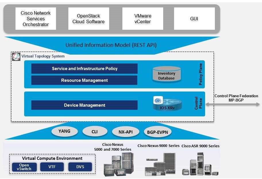
Cisco VTS architecture has two main components: the Policy Plane and the Control Plane. These perform core functions such as SDN control, resource allocation, and core management function.
-
Policy Plane: The policy plane enables Cisco VTS to implement a declarative policy model designed to capture user intent and render it into specific device-level constructs. The solution exposes a set of modular policy constructs that can be flexibly organized into user-defined services for use cases across service provider and cloud environments. These policy constructs are exposed through a set of REST APIs that can be consumed by orchestrators and applications to express user intent, or instantiated through the Cisco VTS GUI. Policy models are exposed as system policies or service policies.
System policies allow administrators to logically group devices into pods within or across data centers to define Admin Domains with common system parameters (for example, BGP-EVPN control plane with distributed Layer 2 and 3 gateways).
The inventory module maintains a database of the available physical entities (for example, data center interconnect [DCI] routers and top-of-rack leaf, spine, and border-leaf switches) and virtual entities (for example, VTFs) in the Virtual Topology System domain. The database also includes interconnections between these entities and details about all services instantiated within a Virtual Topology System domain.
The resource management module manages all available resource pools in the Virtual Topology System domain, including VLANs, VXLAN Network Identifiers (VNIs), IP addresses, and multicast groups.
-
Control Plane: The control plane module serves as the SDN control subsystem that programs the various data planes including the VTFs residing on the x86 servers, hardware leafs, DCI gateways. The Control plane hosts Service Routing (SR) module, which provides routing services to Cisco VTS. The Service Routing (SR) module is responsible for calculating L2 and L3tables and routes to provide connectivity between the different VMs for a given tenant and service chaining. The main components of this module are the VTSR and VTF. VTSR is the controller and Virtual topology forwarder (VTF) runs on each compute server hosting the tenant VMs.
Virtual Topology Forwarder
Virtual Topology Forwarder (VTF) runs on each compute server in the DC and provides connectivity to all tenant VMs hosted on the compute server. VTF supports both intra and inter DC/WAN connectivity. VTF allows Cisco VTS to terminate VXLAN tunnels on host servers by using the VTF as a Software VXLAN Tunnel Endpoint (VTEP). Cisco VTS also supports hybrid overlays by stitching together physical and virtual endpoints into a single VXLAN segment.
VTF has 2 major components—Cisco's VPP (Vector Packet Processing)and VPFa. VPFA is a Cisco agent running on each VMM compute resource. VPFA is FIB agent which receives L2/L3 table forwarding information from VTSR needed to provide the connectivity to local tenant VMs hosted on its compute, and programs them in the VPP.
VTF is deployed as a virtual machine or in vhost mode, to deliver a high-performance software data plane on a host server.
Overview to Cisco VTF and VPP
Cisco VTF is a Cisco Soft switch built on the Cisco Vector Packet Processing (VPP) technology.
The VPP platform is an extensible framework that provides extremely productive and quality switch/router functionality. It is the open source version of the Cisco VPP technology, which is a high performance, packet-processing stack that can run on commodity CPUs.
The benefits of VPP are its high performance, proven technology, modularity, flexibility, and rich feature set.
The VPP platform is built on a packet-processing graph. This modular approach allows anyone to plugin new graph nodes. This makes extensibility rather simple, and the plugins can be customized for specific purposes.
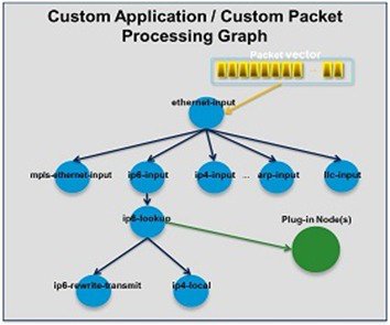
The VPP platform grabs all available packets from RX rings to form a vector of packets. A packet-processing graph is applied, node by node (including plugins) to the entire packet vector. Graph nodes are small and modular, and loosely coupled which makes it easy to include new graph nodes and rewire existing graph nodes.
A plugin can introduce new graph nodes or rearrange the packet-processing graph. You can also build a plugin independent from the VPP source and consider it as an independent component. A plugin can be installed by adding it to a plugin directory.
VTF uses remote plugin that binds into VPP using VPFA (VPF agent). The VPFA interacts with VPP application using low level API. The VPFA exposes netconf or yang based API for remote devices to program the VTF through the VPFA.
VPP + VHOSTUSER
vhost is a solution that allows the user space process to share a number of virtqueues directly with a Kernel driver. The transport mechanism in this case is the ability of the kernel side to access the user space application memory, and a number of ioeventfds and irqfds to serve as the kick mechanism. A QEMU guest uses an emulated PCI device, as the control plane is still handled by QEMU. However once a virtqueue has been set up, the QEMU guest will use the vhost API to pass direct control of a virtqueue to a Kernel driver.
In this model, a vhost_net driver directly passes the guest network traffic to a TUN device directly from the Kernel side, improving performance significantly.
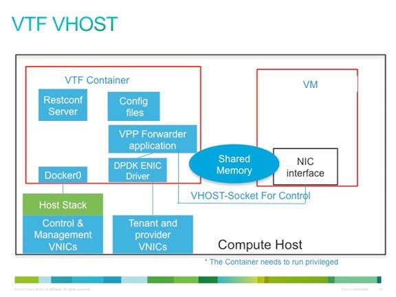
In the above implementation, the guest NFV application directly writes packets into the TX rings, which is shared through a common vhost socket as the RX ring on the VPP . The VPP grabs these packets from the RX ring buffer and forwards the packets using the vector graphs it maintains.
Virtual Topology System High Availability
The Virtual Topology System solution is designed to support redundancy, with two solution instances running on separate hosts in an active-standby configuration.
During initial setup, each instance is configured with both an underlay IP address and a virtual IP address. Virtual Router Redundancy Protocol (VRRP) is used between the instances to determine which instance is active.
The active-instance data is synchronized with the standby instance after each transaction to help ensure consistency of the control-plane information to accelerate failover after a failure. BGP peering is established from both Virtual Topology System instances for the distribution of tenant-specific routes. During the switchover, nonstop forwarding (NSF) and graceful restart help ensure that services are not disrupted.
See the Installing VTS in High Availability Mode section of the Cisco VTS 2.5.2 Installation Guide for the detailed procedure about setting up high availability.
 Feedback