Configure and Troubleshoot Secure Access (SSE) Integration on Catalyst SD-WAN
Available Languages
Contents
Introduction
This document describes how to configure the active-active SSE integration on Catalyst SD-WAN and guides troubleshooting it.
Prerequisites
Requirements
Cisco recommends that you have knowledge of these topics:
- Cisco Software-Defined Wide Area Network (SD-WAN)
- Configuration Groups
- Policy Groups
Components Used
The information in this document is based on these software and hardware versions:
- C8000V version17.15.02
- vManage version 20.15.02
-
Cisco Secure Access account
The information in this document was created from the devices in a specific lab environment. All of the devices used in this document started with a cleared (default) configuration. If your network is live, ensure that you understand the potential impact of any command.
Cisco Secure Access
Cisco Secure Access is a cloud-based Security Service Edge (SSE) solution that converges multiple network security services, delivering them from the cloud to support a hybrid workforce. Cisco SD-WAN Manager leverages REST APIs to retrieve policy information from Cisco Secure Access and distributes this information to Cisco IOS XE SD-WAN devices. This integration enables seamless, transparent, and secure Direct Internet Access (DIA) for users, allowing them to connect from any device, anywhere, securely.
Cisco SSE allows SD-WAN devices to establish connections with SSE providers using IPSec tunnels. This document is intended for users of Cisco Secure Access.
Preliminary configurations
- Enable Domain Lookup for the Device: Navigate to Configuration Groups > System Profile > Global and enable Domain Lookup.
- Configure DNS: The Router can resolve DNS and access the internet on VPN 0.
- Configure NAT DIA: The DIA configuration needs to be present on the router where the SSE tunnel is created.
Create Loopback Interfaces
If both tunnels in an Active/Active configuration connect to the same destination data center and use the same WAN interface as the source, then two loopback IP addresses need to be created.
1. Navigate to Configuration > Configuration Groups > Configuration Group Name> Transport & Management Profile > click on Edit.
2. Click on theplus sign (+) on the right side of the transport VPN Profile (main profile). This opens anAdd Featuremenu located at the far right.
3. Click on Ethernet Interface. It adds a new internet interface under Transport VPN.
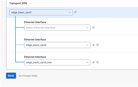
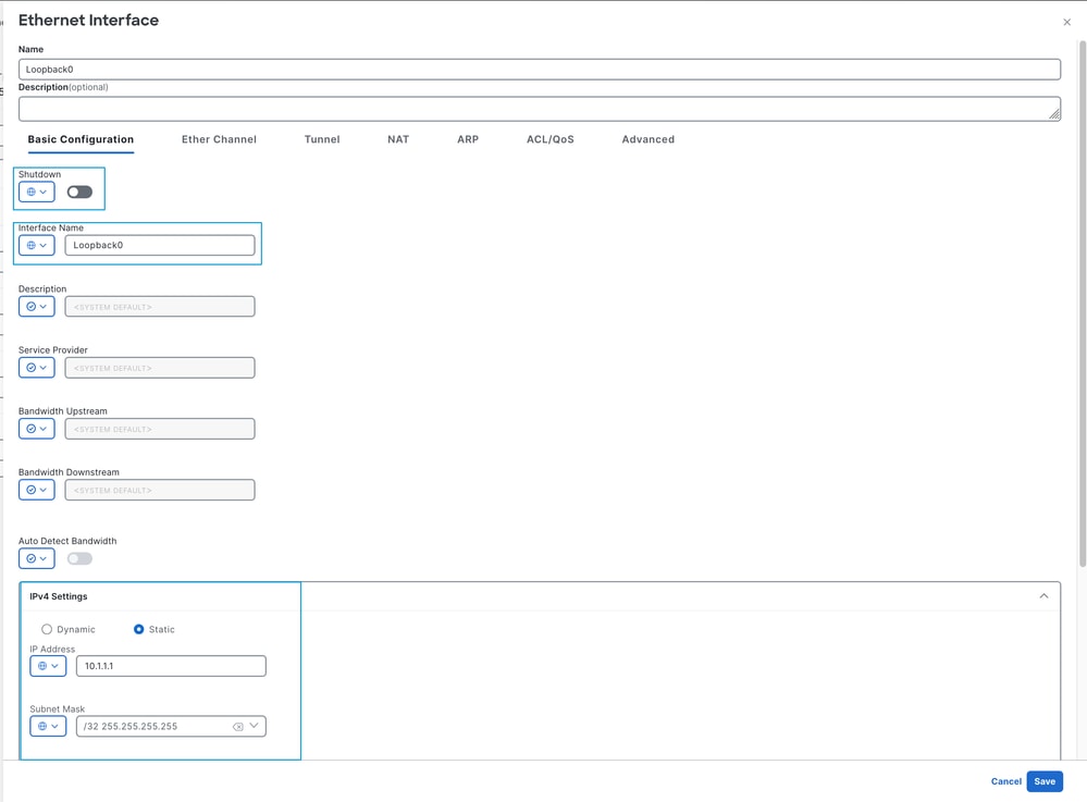
4. Create the two Loopback interfaces using RFC1918 IPv4 addresses, as the Loopback0 example in the picture.
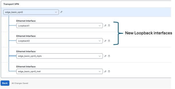
- After applying the loopback configuration, proceed to deploy the configuration change to the device. Notice that the provisioning status changes from1/1to0/1.

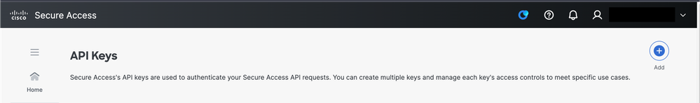
Configure New API Keys on SSE Portal
1. Access to the SSE Portal https://login.sse.cisco.com/
2. Navigate to Admin > API Keys
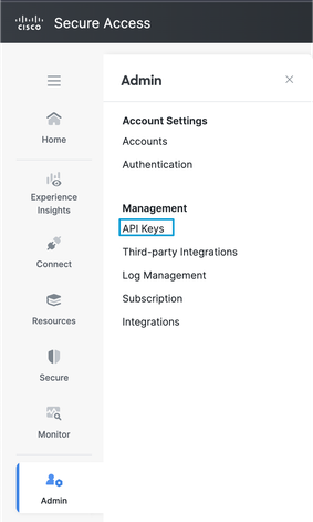
3. Click on Add + and generate a New API Key
4. Ensure that you have Read/Write access to Network Tunnel Group
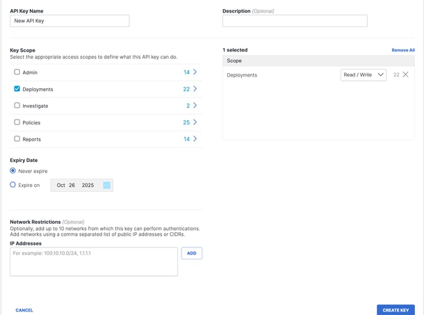
5. Click on Generate Key
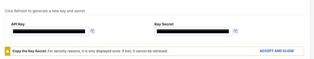
6. Copy the API key and Key Secret into a notepad and select ACCEPT AND CLOSE
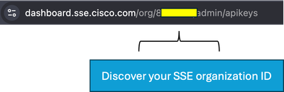
7. Under the URL https://dashboard.sse.cisco.com/#some-numbers#/admin/apikeys the#some-numbers# is your organisation ID. Copy that information into your notepad as well.
Configure SSE on Catalyst Manager
Set up Cloud Credentials
1. Navigate to Administration > Settings > Cloud Credentials > Cloud Provider Credentials, and enable Cisco Secure Access
and enter the details.
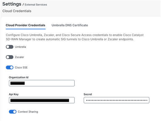
2. Optional: You can enable context sharing for enhanced functionality. For more information, please refer to the Cisco SSE User Guide on context sharing.
Configure SSE Tunnels Using Policy Group
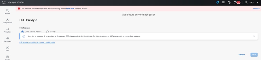
On the SD-WAN Manager navigate to Configuration > Policy Groups > Secure Internet Gateway/Secure Service Edge and click on Add Secure Service Edge (SSE).
1. Configure the SSE Tracker. In this example, the tracker URL is set to http://www.cisco.com, and the source IP address is assigned from one of the loopback interfaces.
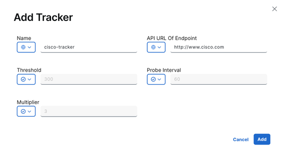
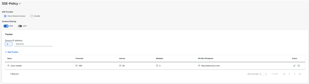
Optionally, since context sharing was enabled when the cloud credentials were configured, VPN is selected as the option in this example.
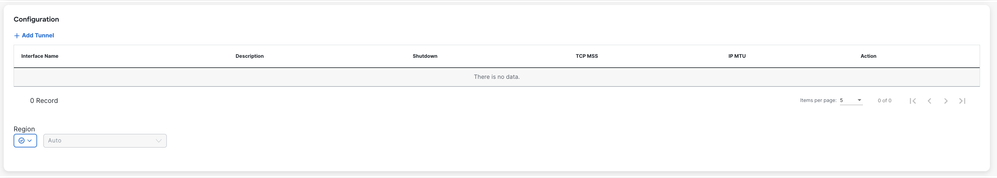
2. Click on Add Tunnel
3. In this example, the Loopback0 interface is used as the tunnel source, while the GigabitEthernet1 interface serves as the WAN interface to route traffic.
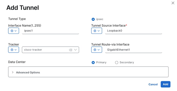
Since the tracker was configured in this example, the setting is changed to Global, and the preconfigured cisco-tracker is selected.
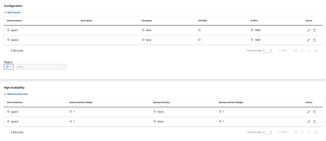
4. For the second tunnel, repeat the same steps using the same parameters, but change the Interface Name from ipsec1 to ipsec2, and the Source Interface Name to Loopback1.
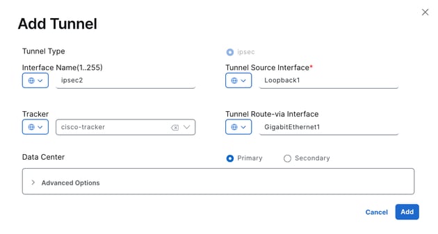
Both tunnels are configured to be active simultaneously, without a backup.
5. Click on Add Interface Pair.
6. Click on Add. The active interface is set to ipsec1, and no backup interface is specified.
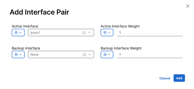
7. The same operation is repeated for the second tunnel, ipsec2.
8. Save the configuration.
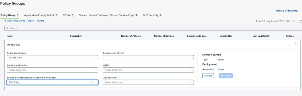
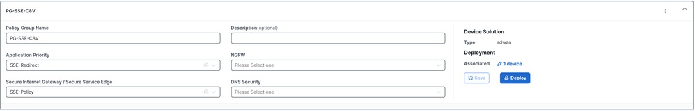
Configure Policy Group
1. You can just select the policy previously created within the policy group and save.
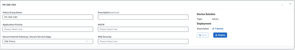
2. Once the device or devices have been associated with the policy group, proceed to deploy the policy group.
Configure Policy Group to Redirect Traffic to SSE
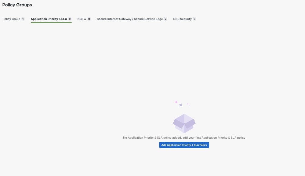
1. On the SD-WAN Manager, navigate to Configuration > Policy Groups > Application Priority & SLA.
- Select Add Application Priority & SLA Policy
- Specify a name for the policy.
2. Once the new policy is displayed, select the Advanced Layout toggle.

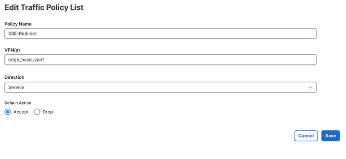
3. Select Add Traffic Policy List.
- Configure the VPNs to redirect traffic to the SSE tunnel.
- Set the Direction and the Default Action as needed and save.
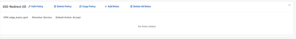
4. Select + Add Rule.
5. Configure your match traffic criteria to redirect traffic to the SSE.
6. Select Accept as the base action, then click on + Action.
7. Look for the Secure Internet Gateway / Secure Service Edge action and set it to Secure Service Edge.
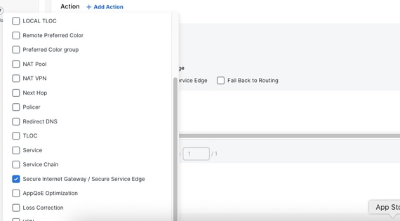
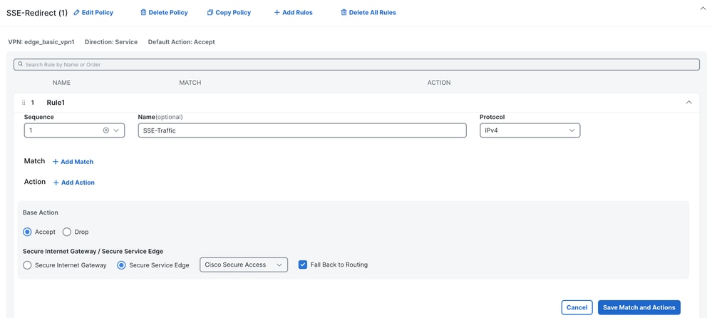
8. Click on Save Match and Actions
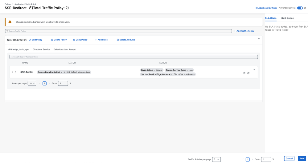
9. Click on Save.
10. Navigate to Configuration > Policy Groups and select the Application Priority policy you just created. Save and then Deploy.
Verify
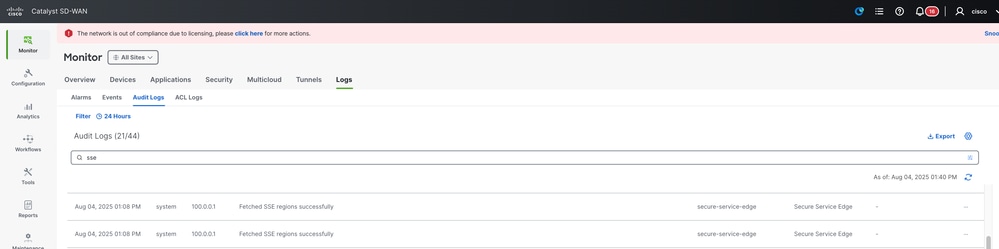
Manager
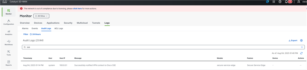
1. Monitor > Logs > Audit Logs and search for "sse".
2. You can verify if the context sharing VPN is enabled successfully by checking the Manager.
Secure Access Dashboard
Context Sharing
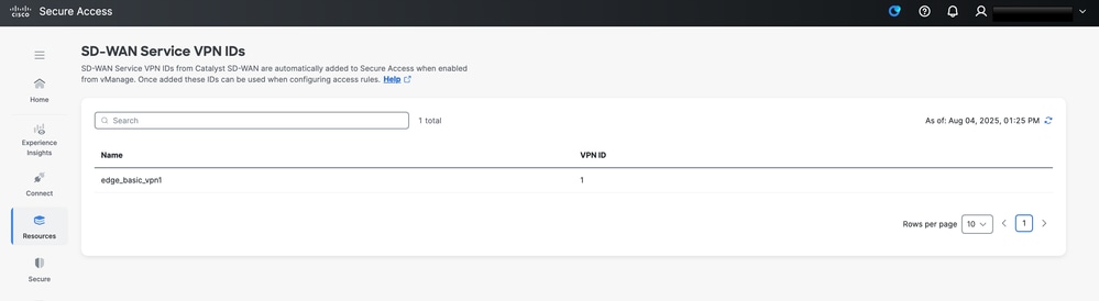
You can verify if the context sharing VPN is enabled successfully by checking the SSE dashboard,Resources > SD-WAN Service VPN IDs
Tunnel Up
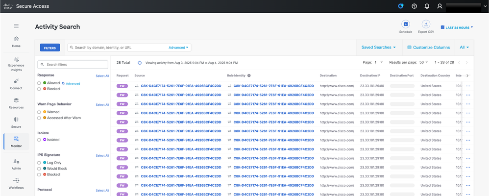
When the tunnel is up and the tracker is operational with traffic flowing through the tunnel, you can validate this by navigating to Monitor > Activity Search. On this screen, you see traffic passing through the tunnel, such as requests to www.cisco.com generated by the tracker. This visibility confirms that the tracker is up and actively monitoring traffic through the tunnel
Comand Line Interface (CLI) Commands
Hub2-SIG#show sse all
***************************************
SSE Instance Cisco-Secure-Access
***************************************
Tunnel name : Tunnel16000001
Site id: 2
Tunnel id: 655184839
SSE tunnel name: C8K-D4CE7174-5261-7E6F-91EA-4926BCF4C2DD
HA role: Active
Local state: Up
Tracker state: Up
Destination Data Center: 44.217.195.188
Tunnel type: IPSEC
Provider name: Cisco Secure Access
Context sharing: CONTEXT_SHARING_SRC_VPN
Related Information
- Configure Context Sharing SD-WAN
- Cisco Secure Access Integration with SD-Routing
- Technical Support & Documentation - Cisco Systems
Revision History
| Revision | Publish Date | Comments |
|---|---|---|
1.0 |
11-Aug-2025
|
Initial Release |
 Feedback
Contact Cisco
- Open a Support Case

- (Requires a Cisco Service Contract)