Introduction
This document describes a configuration that uses the ip nat outside source static command and the IP packets results from the NAT process.
Prerequisites
Requirements
Cisco recommends that you have knowledge of this topic:
Components Used
The information in this document is based on Cisco Routers running Cisco IOS® Software Release.
The information in this document was created from the devices in a specific lab environment. All of the devices used in this document started with a cleared (default) configuration. If your network is live, ensure that you understand the potential impact of any command.
Background Information
This document provides a sample configuration with the use of the ip nat outside source static command and includes a brief description of what happens to the IP packet during the NAT process. Consider thenetwork topologyin this document as an example.
Configure
Network Diagram
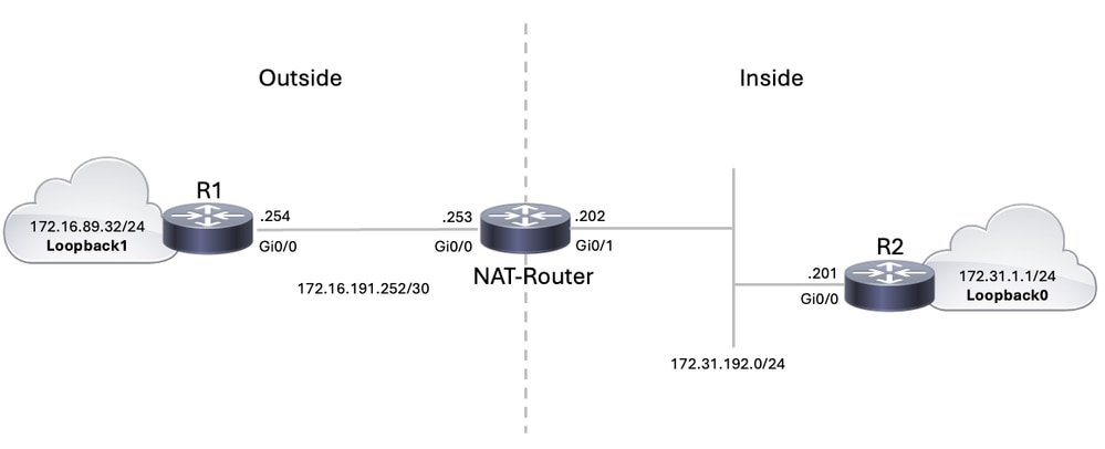
This document uses this network setup.
 Network Diagram
When you issue a ping sourced from Router R1's Loopback1 interface destined for Router R2's Loopback0 interface, this is what happens:
- On the outside interface (Gi0/0) of the NAT-Router, the ping packet appears with a Source Address (SA) of 172.16.89.32 and a Destination Address (DA) of 172.31.1.1.
- NAT translates the SA to the Outside Local Address 172.31.16.5 (corresponding to the ip nat outside source static command configured on the NAT-Router).
- The NAT-Router then checks its routing table for a route to 172.31.1.1.
- If the route does not exist, the NAT-Router drops the packet. However, in this case, the NAT-Router has a route to 172.31.1.1 through the configured static route to subnet 172.31.1.0/24. It forwards the packet to the destination.
- Router R2 receives the packet on its incoming interface (Gi0/0), now with an SA of 172.31.16.5 and a DA of 172.31.1.1.
- To respond, R2 sends an Internet Control Message Protocol (ICMP) echo reply to 172.31.16.5 (the NATted address).
- If R2 does not have a route, it drops the packet. However, in this case, it has a default route towards the NAT-Router.
- Therefore, it sends a reply packet to the NAT-Router, with an SA of 172.31.1.1 and a DA of 172.31.16.5.
- The NAT-Router sees the packet and checks for a route to the 172.31.16.5 address.
- If it does not have one, it responds with an ICMP unreachable reply.
- In this case, it has a static route configured to 172.31.16.0/24 subnet pointing to R1.
- It translates the packet back to the 172.16.89.32 address and forwards it out its outside interface (Gi0/0).
Configurations
This document uses these configurations:
| Router R1 |
hostname R1
!

!--- Output suppressed.

!
interface Loopback1
 ip address 172.16.89.32 255.255.255.0
!
interface GigabitEthernet0/0
 ip address 172.16.191.254 255.255.255.252
 duplex auto
 speed auto
!
interface GigabitEthernet0/1
 no ip address
 shutdown
!
!--- Output suppressed.

ip route 0.0.0.0 0.0.0.0 172.16.191.253

!--- Default route to forward packets to NAT-Router.
!--- Output suppressed.
|
| Router NAT-Router |
hostname NAT-Router
!

!--- Output suppressed.

!
interface GigabitEthernet0/0
 ip address 172.16.191.253 255.255.255.252
 ip nat outside
 ip virtual-reassembly in
 duplex auto
 speed auto
!
interface GigabitEthernet0/1
 ip address 172.31.192.202 255.255.255.0
 ip nat inside
 ip virtual-reassembly in
 duplex auto
 speed auto
!

!--- ip nat command defines GigabitEthernet0/1 as a NAT inside interface and GigabitEthernet0/0 as a NAT outside interface.

!--- Output suppressed.

!
no ip http server
no ip http secure-server
ip nat outside source static 172.16.89.32 172.31.16.5
ip route 172.31.1.0 255.255.255.0 172.31.192.201
ip route 172.31.16.0 255.255.255.0 172.16.191.254
!

!--- Outside local address is defined as 172.31.16.5.
!--- Static routes for reaching the loopback interfaces on R2 and subnet 172.31.16.0 towards R1.
|
Note: Note that in this particular scenario, a static route pointing to Loopback1 on R1 is not needed. This is because when the ICMP reply enters the NAT router, the routing table is checked for the destination first, and then the address translation is performed.
| Router R2 |
hostname R2
!

!--- Output suppressed.

!
interface Loopback0
 ip address 172.31.1.1 255.255.255.0
!
interface GigabitEthernet0/0
 ip address 172.31.192.201 255.255.255.0
 duplex auto
 speed auto
!

!--- Output suppressed.

ip route 0.0.0.0 0.0.0.0 172.31.192.202

!--- Default route to forward packets to NAT-Router.
!--- Output suppressed.
|
Verification
Use the show ip nat translations command to check the translation entries, as this output shows:
NAT-Router#show ip nat translations
Pro Inside global      Inside local       Outside local      Outside global
--- ---                ---                172.31.16.5        172.16.89.32
icmp 172.31.1.1:21     172.31.1.1:21      172.31.16.5:21     172.16.89.32:21
NAT-Router#
Troubleshooting
This example uses NAT translation debugging and IP packet debugging to demonstrate the NAT process.

Caution: Because the debug commands generate a significant amount of output, use them only when traffic on the IP network is low so that other activity on the system is not adversely affected.
Note: These debug outputs were taken from routers running Cisco IOS software. The collection of these debug outputs can vary based on the platform used.
Note: Refer to Important Information on Debug Commands before you use debug commands.
This output is the result of using the debug ip packet and debug ip nat commands simultaneously on the NAT-Router, while pinging from R1 loopback1 interface address (172.16.89.32) to R2 loopback0 interface address (172.31.1.1).
This output shows the first packet that arrives on the outside interface of NAT-Router. The source address of 172.16.89.32 gets translated to 172.31.16.5. The ICMP packet is forwarded toward the destination out the GigabitEthernet0/1 interface.
*Sep 19 15:34:39.925: NAT: s=172.16.89.32->172.31.16.5, d=172.31.1.1 [100]
*Sep 19 15:34:39.925: IP: s=172.31.16.5 (GigabitEthernet0/0), d=172.31.1.1 (GigabitEthernet0/1), len 100, output feature, NAT Inside(8), rtype 1, forus FALSE, sendself FALSE, mtu 0, fwdchk FALSE
*Sep 19 15:34:39.926: IP: s=172.31.16.5 (GigabitEthernet0/0), d=172.31.1.1 (GigabitEthernet0/1), len 100, output feature, Common Flow Table(29), rtype 1, forus FALSE, sendself FALSE, mtu 0, fwdchk FALSE
*Sep 19 15:34:39.926: IP: s=172.31.16.5 (GigabitEthernet0/0), d=172.31.1.1 (GigabitEthernet0/1), len 100, output feature, Stateful Inspection(30), rtype 1, forus FALSE, sendself FALSE, mtu 0, fwdchk FALSE
*Sep 19 15:34:39.927: IP: s=172.31.16.5 (GigabitEthernet0/0), d=172.31.1.1 (GigabitEthernet0/1), len 100, output feature, NAT ALG proxy(63), rtype 1, forus FALSE, sendself FALSE, mtu 0, fwdchk FALSE
*Sep 19 15:34:39.927: IP: s=172.31.16.5 (GigabitEthernet0/0), d=172.31.1.1 (GigabitEthernet0/1), g=172.31.192.201, len 100, forward
*Sep 19 15:34:39.928: IP: s=172.31.16.5 (GigabitEthernet0/0), d=172.31.1.1 (GigabitEthernet0/1), len 100, sending full packet
This output shows the return packet sourced from 172.31.1.1 with a destination address of 172.31.16.5, which gets translated to 172.16.89.32. The resultant ICMP packet gets forwarded out the GigabitEthernet0/0 interface (NAT-Router).
*Sep 19 15:34:39.930: NAT*: i: icmp (172.31.1.1, 20) -> (172.31.16.5, 20) [100]
*Sep 19 15:34:39.930: NAT*: s=172.31.1.1, d=172.31.16.5->172.16.89.32 [100]
The exchange of ICMP packets continues. The NAT process for this debug output is the same as the previous output.
*Sep 19 15:34:39.932: NAT*: o: icmp (172.16.89.32, 20) -> (172.31.1.1, 20) [101]
*Sep 19 15:34:39.932: NAT*: s=172.16.89.32->172.31.16.5, d=172.31.1.1 [101]
*Sep 19 15:34:39.933: NAT*: i: icmp (172.31.1.1, 20) -> (172.31.16.5, 20) [101]
*Sep 19 15:34:39.933: NAT*: s=172.31.1.1, d=172.31.16.5->172.16.89.32 [101]
*Sep 19 15:34:39.935: NAT*: o: icmp (172.16.89.32, 20) -> (172.31.1.1, 20) [102]
*Sep 19 15:34:39.935: NAT*: s=172.16.89.32->172.31.16.5, d=172.31.1.1 [102]
*Sep 19 15:34:39.936: NAT*: i: icmp (172.31.1.1, 20) -> (172.31.16.5, 20) [102]
*Sep 19 15:34:39.936: NAT*: s=172.31.1.1, d=172.31.16.5->172.16.89.32 [102]
*Sep 19 15:34:39.938: NAT*: o: icmp (172.16.89.32, 20) -> (172.31.1.1, 20) [103]
*Sep 19 15:34:39.938: NAT*: s=172.16.89.32->172.31.16.5, d=172.31.1.1 [103]
*Sep 19 15:34:39.939: NAT*: i: icmp (172.31.1.1, 20) -> (172.31.16.5, 20) [103]
*Sep 19 15:34:39.939: NAT*: s=172.31.1.1, d=172.31.16.5->172.16.89.32 [103]
*Sep 19 15:34:39.940: NAT*: o: icmp (172.16.89.32, 20) -> (172.31.1.1, 20) [104]
*Sep 19 15:34:39.940: NAT*: s=172.16.89.32->172.31.16.5, d=172.31.1.1 [104]
*Sep 19 15:34:39.942: NAT*: i: icmp (172.31.1.1, 20) -> (172.31.16.5, 20) [104]
*Sep 19 15:34:39.942: NAT*: s=172.31.1.1, d=172.31.16.5->172.16.89.32 [104]
Summary
When the packet travels from outside to inside, translation occurs first, and then the routing table is checked for the destination.
When the packet travels from inside to outside, the routing table is checked for the destination first, and then translation occurs.
Refer to NAT Order of Operation for further information.
Take note of the part of the IP packet that gets translated when used with each of the previous commands. This table contains the guideline:
| Command |
Action |
| ip nat outside source static |
- Translates the source of the IP packets that travel outside to inside.
- Translates the destination of the IP packets that travel inside to outside.
|
| ip nat inside source static |
- Translates the source of IP packets that travel inside to outside.
- Translates the destination of the IP packets that travel outside to inside.
|
These guidelines indicate that there is more than one way to translate a packet. Based on your specific needs, determine how to define the NAT interfaces (inside or outside) and what routes the routing table contains before or after translation. Keep in mind that the portion of the packet that is translated depends upon the direction the packet travels, and how you configure NAT.
Related Information
 Feedback