Cisco Catalyst 8500 Series Edge Platforms and Microsoft Azure ExpressRoute Joint Validated Design Guide
Available Languages
Bias-Free Language
The documentation set for this product strives to use bias-free language. For the purposes of this documentation set, bias-free is defined as language that does not imply discrimination based on age, disability, gender, racial identity, ethnic identity, sexual orientation, socioeconomic status, and intersectionality. Exceptions may be present in the documentation due to language that is hardcoded in the user interfaces of the product software, language used based on RFP documentation, or language that is used by a referenced third-party product. Learn more about how Cisco is using Inclusive Language.
In today’s ever changing multi-cloud world, Enterprise Networks are adopting private and public cloud services to host business-critical applications. The reduced Total Cost of Ownership (TCO) and ability to elastically scale applications based on network demands along with guaranteed availability for workloads across multiple geographic regions are some of the key benefits driving this change.
The role of Enterprise Edge platform is very important in establishing a reliable connection from Customer network to cloud end point. To make the cloud deployment easier, Cisco and Microsoft have partnered to come up with a Joint Validated Design guide (JVD) using Cisco’s recently launched Catalyst 8500 Series Edge Platforms with Microsoft Azure ExpressRoute (ER) connectivity options.
This JVD is a one stop guide that brings feature level clarity for the Cisco Catalyst 8500 Series Edge Platform configuration for extending your on-premises networks into Microsoft Cloud over a private connection as well as connectivity to Microsoft cloud services such as Microsoft Azure and Microsoft 365.
The intended audience for this document includes sales engineers, field consultants, professional services staff, IT managers, partner engineering staff, and customers deploying the Microsoft Azure ExpressRoute with Cisco Catalyst 8500 Series Edge Platforms. External references are provided wherever applicable, but readers are expected to be familiar with the technology, infrastructure, and enterprise security policies of the customer installation.
Cisco-Microsoft Joint Validated Designs provide guidelines for creating an end-to-end solution that enable you to make informed decisions with the goal of successfully creating a hybrid cloud deployment.
This document describes the steps required to extend your on-premises network into Microsoft Azure with ExpressRoute using the Cisco Catalyst 8500 Series Edge Platforms Series Routers. To connect to Microsoft Azure services using ExpressRoute, Microsoft provides best practices for network security, optimize routing, asymmetric routing, and NAT. This guide will focus on how to implement these best practices with Catalyst 8500 Series Edge Platforms configurations, recommend advanced features and services. It is important to note that this guide is not meant to be a comprehensive overview of the Catalyst 8500 Series Edge Platforms platform and routing technologies, see References section for platform and feature configuration guides.
Cisco validation provides further confirmation of solution compatibility, connectivity, and correct operation for the on-premises deployment. Although readers of this document are expected to have sufficient knowledge to install and configure the products used, the Cisco-Microsoft Joint Validated Design provides configuration details that are important to the deployment of this solution.
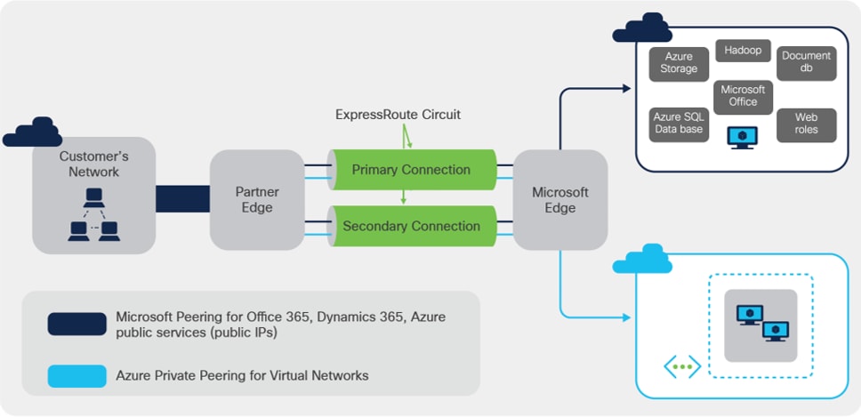
The ExpressRoute solution enables layer 3 connectivity between your on-premises network and the Microsoft Cloud through a connectivity provider or directly to Microsoft’s routers. Connectivity can be from an any-to-any (IP VPN) network, a point-to-point Ethernet connection, through a virtual cross-connection via an Ethernet exchange or through a physical cross-connection directly to Microsoft’s router. The connectivity models are detailed at ExpressRoute connectivity models.
ExpressRoute connectivity
ExpressRoute connections do not go over the public Internet, which allows ExpressRoute connections to offer more reliability, faster speeds, consistent latencies, and higher security than typical connections over the Internet. As shown in Figure 1, ExpressRoute circuits have multiple routing domains associated with them: Azure private peering, and Microsoft peering. Each of the routing domains are configured in separate Virtual Routing and Forwarding (VRF) domains on a pair of Catalyst 8500 Series Edge Platforms routers for high availability.
ExpressRoute connectivity models can be categorized into two buckets: Partner model and Direct model. Cloud Exchange co-location, point-to-point Ethernet connection and any-to-any (IP VPN) connection are provided via Service Provider enabled connectivity; whereas ExpressRoute Direct model enables Customer edge devices to be placed at ExpressRoute sites that are Microsoft’s global network peering locations strategically distributed across the world. ExpressRoute Direct provides dual 100 Gbps or 10 Gbps connectivity, which supports Active/Active connectivity at scale. The ‘Partner edge’ block shown in figure 1 does not exist in case of ExpressRoute Direct model. The Catalyst 8500 platform pair is deployed as Customer Edge in both deployment model.
ExpressRoute capabilities and features are identical across all the connectivity models. The Catalyst 8500 Series Edge Platforms physical connectivity configuration to each of the service providers may vary, but the configuration to ExpressRoute will be identical.
Cisco launched the all-new Cisco Catalyst 8500 Series Edge Platforms in October 2020. These platforms are highly capable and purpose-built to address traditional WAN, emerging SD-WAN and co-location use cases.
The Cisco Catalyst 8500 Series Edge Platforms are fixed form factor, 1 rack-unit aggregation platforms. The top end models C8500-12X4QC and C8500-12X use Cisco’s the 3rd generation of the highly reputed QuantumFlow Processor ASIC (QFP 3.0) to orchestrate highly scalable data plane. On the lower end of the portfolio, C8500L-8S4X platform orchestrates reimagined advanced flow-based distribution using x86 System-on-Chip (SoC) to orchestrate the data plane.
The Catalyst 8500 Series Edge Platforms include the following components:
● Built-in route processor
● Built-in embedded services processor
● Built-in aggregation hardware for different types of interfaces and connectivity
● Redundant AC or DC power supplies with on/off switches
● Removable fan assembly
● On/off switches on the power supplies (AC and DC)
With the top end models, the QFP 3.0 enhances the hardware-based forwarding to a whole new level. Along with embedded services applications and high-speed forwarding, the QFP 3.0 also hosts integrated Layer 2 subsystem and IPsec crypto functionality within the same ASIC.
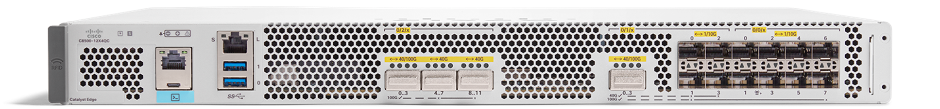
C8500-12X4QC
The C8500-12X4QC platform, shown in figure 2, can deliver aggregate of up to 197 Gbps CEF and up to 135 Gbps IPsec throughput performance at 1400B payload size. It offers 4 QSFP and 12 SFP+ built-in interface options. It has total 240 Gbps of aggregation capacity which can be consumed by combination of 1 GE, 10GE, 40 GE and 100 GE speeds for external connectivity. The small size of 1 rack unit and port speed flexibility makes this a powerful platform to offer highly scalable services for ExpressRoute connectivity using 100 GE and 10 GE port options.
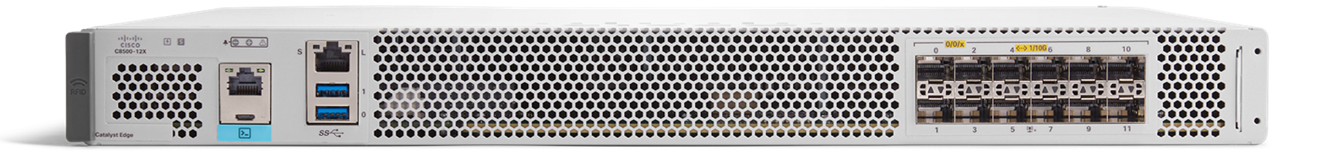
C8500-12X
The C8500-12X platform, shown in figure 3, is younger sibling of C8500-12X4QC and can deliver aggregate of up to 118 Gbps CEF and up to 84 Gbps of IPsec throughput performance at 1400B payload size. As stated earlier both use powerful QFP 3.0 ASIC that drives data plane performance. C8500-12X offers high density TenGigabitEthernet connectivity options with built-in 12 SFP+ ports delivering 1 GE and 10 GE speeds for external connectivity. This platform can offer 10 GE ExpressRoute connectivity options in 1 rack unit form.
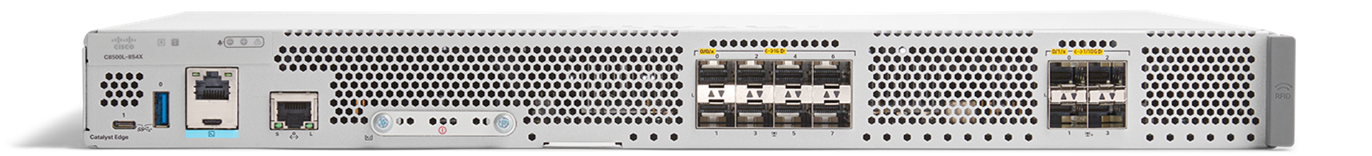
C8500L-8S4X
The C8500L-8S4X platform, shown in figure 4, can deliver aggregate of up to 20 Gbps CEF and up to 19 Gbps of IPsec throughput performance at 1400B payload size. It offers 10 GE ExpressRoute connectivity using built in 4 SFP+ ports. It also hosts 8 SFP ports for 1 GE external connectivity. Here the data plane uses x86 flow-based distribution architecture to accelerate stateful traffic performance.
All the three platforms inherit benefits of Cisco’s well established IOS XE operating system. They can be hosted in ‘autonomous’ mode for traditional routing and ‘controller’ mode for SD-WAN use-cases with a single software image. The best part is they are equally capable for WAN edge use-cases and ExpressRoute CPE use-cases as they have complete feature parity with the well-known ASR 1000 Enterprise Routing Platforms.
Catalyst 8500 Series platforms can aggregate multiple WAN connections and network services, including encryption and traffic management, and forward them across WAN connections at line speeds.
All the front panel ports on the three platforms support MACsec for line rate encryption, which makes the portfolio more suitable for ExpressRoute Direct connectivity using MACsec.
Catalyst 8500 Series Edge Platforms Series routers offer elastic service delivery; programmability and automation; up to five-nines availability; comprehensive and flexible QoS; and advanced services, such as IPsec VPN and Application Visibility and Control (AVC) for enterprise networks.
The configuration guide will include numerous value substitutions provided for the purpose of example only. Any references to IP addresses, device IDs, shared secrets or keys account information or project names should be replaced with the appropriate values for your environment when following this guide. Values unique to your environment will be highlighted in bold.
This guide is not meant to be a comprehensive setup for entire device configuration for all network connectivity, e.g., the same device may also have connectivity to the enterprise data center, campus, or branches and that configuration is outside the scope of this guide. This configuration guide will focus on the connectivity to ExpressRoute.
Following list provides a high-level overview of the configuration process that will be covered.
High-level overview of Catalyst 8500 Series Edge Platforms Configuration process
1. Interface Configurations
a. 802.1Q-in-Q VLAN ID Sample Interface Configuration
b. 802.1Q VLAN ID Sample Interface Configuration
c. MACsec Enablement for ExpressRoute Direct
2. BGP Configurations
a. Setup eBGP Sessions
b. Advertise Prefixes Over the BGP Session to Azure
c. Filter Prefixes Received from Azure (Optional)
d. High Availability and Optimize Routing Configuration
e. AS Path Prepending to Influence Routing
f. Avoid Asymmetric Routing
g. Bidirectional Forwarding Detection
h. NAT Configuration
i. NAT Common Best Practices
3. Route Redistribution into EIGRP
4. Advanced Feature Configurations
a. Flexible Netflow Configuration
b. Quality of Service Configuration
5. Advanced Services Configurations
a. Application Visibility and Control (AVC) Configuration
b. IPsec VPN Configuration
At this stage, it is assumed that all pre-requisites for ExpressRoute are met, and you are ready for configuring the C8500 CPE platform:
● The ExpressRoute prerequisites & checklist, the ExpressRoute circuits or ExpressRoute Direct circuits have been created. Indirectly, Azure side configuration is completed.
● For ExpressRoute Partner model, the circuit is provisioned by the service provider.
● For the ExpressRoute Direct model, the C8500 CPE devices are physically connected in ExpressRoute Direct peering location.
The first step in configuring your Cisco Catalyst 8500 Series Edge Platforms for use with the ExpressRoute connectivity is to ensure that licensing is enabled for the required feature set. DNA-Advantage subscription provides the necessary features, e.g., BGP, NAT, VRF-Lite, IPv4/IPv6 dual-stack as well as the advanced services such as NBAR/AVC, IPsec, MACsec, etc.
Refer to the Catalyst 8500 Series Edge Platforms Ordering Guide for more details on Catalyst 8500 Series Edge Platforms license information.
Configuration: ExpressRoute Peering on Azure Portal
ExpressRoute Service Provider Model: Azure Portal Configuration
Follow the ExpressRoute peering steps in Azure portal.
ExpressRoute Direct Model: Azure Portal Configuration
Follow the ExpressRoute Direct peering steps in Azure portal.
Configuration: Catalyst 8500 Series Edge Platforms
Two Router Deployment vs. One Router Deployment
We recommend the deployment of two Catalyst 8500 Series Edge Platforms in a redundant pair to connect to the ExpressRoute service. Each router will need two Q-in-Q sub-interfaces on the physical interface. At the Microsoft Edge (see Figure 1) an ExpressRoute service is terminated on a pair of Microsoft ExpressRoute Edge (MSEE) routers. The MSEE routers hand off to a pair of Connectivity Provider routers, and then down to your Catalyst 8500 Series Edge Platforms routers. Microsoft will always have two BGP neighbors for each of the peering types.
As an example, assume Microsoft defines an outer dot1Q tag of 100 for ER circuit, and the customer requests an inner tag of 301 for the Microsoft peering, and 300 for the private peering. Table 1 outlines the example of mapping of Interfaces, sub-interfaces, VRFs and their respective peering to ER in the customer edge dual router design.
Microsoft side of the network ensures redundancy is implemented at every stage. It is recommended to opt for dual Customer router deployment and avoid single point of failure.
Table 1. Router, Interface, Sub-interfaces, VRFs and Peering for Customer Edge Dual Router Design
| Routers |
R1 |
R2 |
||||||
| Interfaces |
Hu0/2/0 |
Hu0/1/0 |
Hu0/2/0 |
Hu0/1/0 |
||||
| Interface description |
Connection to ER Primary |
Connection to customer corporate network |
Connection to ER Secondary |
Connection to customer corporate network |
||||
| Sub-interfaces |
0/2/0.301 |
0/2/0.300 |
0/1/0.301 |
0/1/0.300 |
0/2/0.301 |
0/2/0.300 |
0/1/0.301 |
0/1/0.300 |
| Sub-interface description |
Primary Microsoft Peering |
Primary Private Peering |
DMZ VLAN |
Corporate VLAN |
Secondary Microsoft Peering |
Secondary Private Peering |
DMZ VLAN |
Corporate VLAN |
| Encapsulation |
dot1Q 100 second-dot1q 301 or dot1Q 301 |
dot1Q 100 second-dot1q 300 or dot1Q 300 |
dot1Q 301 |
dot1Q 300 |
dot1Q 100 second-dot1q 301 or dot1Q 301 |
dot1Q 100 second-dot1q 300 or dot1Q 300 |
dot1Q 301 |
dot1Q 300 |
| VRFs* |
301 |
300 |
301 |
300 |
301 |
300 |
301 |
300 |
| IP Addresses |
198.137.97.25/30 |
192.168.30.17/30 |
10.1.30.1/30 |
10.1.30.5/30 |
198.137.97.29/30 |
192.168.30.21/30 |
10.1.30.9/30 |
10.1.30.13/30 |
Note: It is best practice to separate private peering and Microsoft peering with two separate VRFs. The private peering is considered trusted, whereas the Microsoft peering is a public network. The customer can send each VRFs/VLANs to the appropriate security zone before entering/exiting their corporate VLANs.
Note: Currently the document is written with IPv4 addressing scheme for connectivity. ExpressRoute also offers IPv6 addressing, which would not necessarily change feature and functionality from configuration perspective.
Unless otherwise stated, this configuration guide provides configuration example on Router R1. Router R2 should have the same configuration as R1, except for IP addresses/subnets. The sub-interface, IP address, and VRF will use the example provided in Table 1.
This section provides the interface configuration of Cisco Catalyst 8500 Series Edge Platforms to connect to ER. At least one internal facing interface is required to connect to your own network, and one external facing interface is required to connect to ExpressRoute.
You will require a sub-interface per peering in every router you connect to ER. A sub-interface can be identified with an 802.1Q-in-Q VLAN ID or 802.1Q VLAN ID based on the connectivity providers’ requirement and an IP address.
Follow ER IP address requirements for the BGP peering.
802.1Q-in-Q VLAN ID Sample Interface configuration
In 802.1Q-in-Q configuration scenario, Microsoft uses both inner and outer tags for peering the networks.
vrf definition 300
rd 65021:300
!
address-family ipv4
exit-address-family
!
address-family ipv6
exit-address-family
!
vrf definition 301
rd 65021:301
!
address-family ipv4
exit-address-family
!
address-family ipv6
exit-address-family
!
interface HundredGigE0/1/0
description Customer Corporate Network Connection
no ip address
!
interface HundredGigE0/1/0.300
description Customer Corporate VLAN for Private Peering
encapsulation dot1Q 300
vrf forwarding 300
ip address 10.1.30.1 255.255.255.252
!
interface HundredGigE0/1/0.301
description Customer DMZ VLAN for Microsoft Peering
encapsulation dot1Q 301
vrf forwarding 301
ip address 10.1.30.5 255.255.255.252
!
interface HundredGigE0/2/0
description Customer ExpressRoute Primary Connection
no ip address
dot1q tunneling ethertype 0x9100
! The default ethertype is 0x8100, can be changed to 0x88A8|0x9100|0x9200 to meet the connectivity provider’s requirement
!
interface HundredGigE0/2/0.300
description Customer Private Peering to Azure
encapsulation dot1Q 100 second-dot1q 300
vrf forwarding 300
ip address 192.168.30.17 255.255.255.252
ipv6 address FD:1:1:30FF::1/126
!
interface HundredGigE0/2/0.301
description Customer Microsoft Peering to Azure
encapsulation dot1Q 100 second-dot1q 301
vrf forwarding 301
ip address 198.137.97.25 255.255.255.252
!
802.1Q VLAN ID Sample Interface configuration
When using ExpressRoute Direct connectivity or a service provider connectivity with dot1Q hand-off, the outer dot1Q tag is not required. In 802.1Q configuration scenario, Microsoft uses only a single tag as defined by Customer.
The configuration for ER facing interfaces will look like below:
vrf definition 300
rd 65021:300
!
address-family ipv4
exit-address-family
!
address-family ipv6
exit-address-family
!
vrf definition 301
rd 65021:301
!
address-family ipv4
exit-address-family
!
address-family ipv6
exit-address-family
!
interface HundredGigE0/1/0
description Customer Corporate Network Connection
no ip address
!
interface HundredGigE0/1/0.300
description Customer Corporate VLAN for Private Peering
encapsulation dot1Q 300
vrf forwarding 300
ip address 10.1.30.1 255.255.255.252
!
interface HundredGigE0/1/0.301
description Customer DMZ VLAN for Microsoft Peering
encapsulation dot1Q 301
vrf forwarding 301
ip address 10.1.30.5 255.255.255.252
!
interface HundredGigE0/2/0
description Customer ExpressRoute Primary Connection
no ip address
!
interface HundredGigE0/2/0.300
description Customer Private Peering to Azure
encapsulation dot1Q 300
vrf forwarding 300
ip address 192.168.30.17 255.255.255.252
ipv6 address FD:1:1:30FF::1/126
!
interface HundredGigE0/2/0.301
description Customer Microsoft Peering to Azure
encapsulation dot1Q 301
vrf forwarding 301
ip address 198.137.97.25 255.255.255.252
!
Note: The MTU for the ExpressRoute interface is 1500 Bytes, which is the default MTU on Catalyst 8500 Series Edge Platforms.
MACsec Enablement for ExpressRoute Direct
ExpressRoute Direct connectivity allows MACsec to secure the connections between the Catalyst 8500 platform and Microsoft’s edge router. 10 Gbps and 100 Gbps ExpressRoute Direct circuits can be enabled with MACsec connectivity using Catalyst 8500 platforms. MACsec configuration using PowerShell steps are listed on Azure documentation here.
Microsoft Azure supports only Extended Packet Numbering (XPN) AES-128 and AES-256 ciphers for MACsec connectivity. Both extended packet numbering (XPN) and non-XPN ciphers are supported. Catalyst 8500 Series Edge Platform supports XPN ciphers for 100 Gbps ports as you see in below table. For 10 Gbps ports, you can make use of non-XPN ciphers to establish MACsec connectivity with Azure ExpressRoute. The support for XPN ciphers for 10 Gbps ports is planned in upcoming IOS XE release.
Following are various ciphers that can be enabled for Catalyst 8500 platform built-in ethernet ports:
Table 2. MACsec cipher support for Catalyst 8500
| Port Speed |
Supported cipher-suite |
| 10 Gbps |
gcm-aes-128, gcm-aes-256 |
| 100 Gbps |
gcm-aes-128, gcm-aes-256, gcm-aes-xpn-128, gcm-aes-xpn-256 |
First, we need to configure MKA policy and the key chain with desired cipher suite for MACsec connectivity. The key-string here should match with the same provisioned using PowerShell scripts on Azure side.
mka policy xpn-p1
macsec-cipher-suite gcm-aes-xpn-256
!
key chain azure-macsec macsec
key 1
cryptographic-algorithm aes-256-cmac
key-string 1234567890abcdef1234567890abcdef1234567890abcdef1234567890abcdef
!
Microsoft ExpressRoute configuration mandates disabling Secure Channel Identifier (SCI) in MACsec configuration. This functionality is supported from IOS XE 17.6 release for Catalyst 8500 (C8500-12X4QC and C8500-12X) as well as ASR 1000 platforms using ‘macsec disable-sci’ configuration CLI.
Based on the MACsec peering, MACsec is enabled using pre-configured policy and key chain under interface configuration. This is done under the parent interface for HundredGigE connectivity as shown below:
interface HundredGigE0/2/0
no ip address
mka policy xpn-p1
mka pre-shared-key key-chain azure-macsec
macsec disable-sci
macsec
!
Note: With IOS XE 17.6 onward releases, you can use C8500-12X4QC, C8500-12X platforms for MACsec 100 Gbps and 10 Gbps connectivity with Azure as per built-in port configurations. The support for SCI disablement on C8500L-8S4X is planned in upcoming release.
Additional details on ExpressRoute encryption function are available here.
Setup eBGP sessions
You must setup a BGP session with Microsoft for every peering. The sample below enables you to setup a BGP session with Microsoft. If the IPv4 address you used for your sub-interface was a.b.c.d, the IP address of the BGP neighbor (Microsoft) will be a.b.c.(d+1). The last octet of the BGP neighbor's IPv4 address will always be an even number. Similar logic is applied for IPv6 addressing as well.
Follow ER Autonomous System Number requirements for the peering.
router bgp 65021
bgp router-id 198.137.97.25
bgp log-neighbor-changes
!
address-family ipv4 vrf 300
neighbor 192.168.30.18 remote-as 12076
neighbor 192.168.30.18 activate
neighbor 192.168.30.18 next-hop-self
neighbor 192.168.30.18 soft-reconfiguration inbound
neighbor 192.168.30.18 route-map only-advertise-private out
exit-address-family
!
address-family ipv6 vrf 300
neighbor FD:1:1:30FF::2 remote-as 12076
neighbor FD:1:1:30FF::2 activate
neighbor FD:1:1:30FF::2 next-hop-self
neighbor FD:1:1:30FF::2 soft-reconfiguration inbound
exit-address-family
!
address-family ipv4 vrf 301
neighbor 198.137.97.26 remote-as 12076
neighbor 198.137.97.26 activate
neighbor 198.137.97.26 next-hop-self
neighbor 198.137.97.26 soft-reconfiguration inbound
exit-address-family
!
!
Note: Password configuration is an optional feature for the ER BGP peering and not enabled by default. See BGP Command Reference for more information to set up a password on the BGP peering.
Advertise Prefixes Over the BGP Session to Azure
Use network statement or redistribution from IGP to advertise your internal network prefixes to Azure.
router bgp 65021
!
address-family ipv4 vrf 300
network 10.1.30.4 mask 255.255.255.252
redistribute connected
redistribute static
!
address-family ipv6 vrf 300
network 2001:5B0:4406:30::/64
!
address-family ipv4 vrf 301
network 10.1.30.0 mask 255.255.255.252
redistribute connected
redistribute static
!
address-family ipv6 vrf 301
network 2001:5B0:4406:31::/64
!
Microsoft peering does not accept default route or private IP addresses (RFC 1918), the sample below use prefix-list to filter them out.
router bgp 65021
!
address-family ipv4 vrf 301
neighbor 198.137.97.26 prefix-list block-list out
!
ip prefix-list block-list deny 10.0.0.0/8 le 32
ip prefix-list block-list deny 127.0.0.0/8 le 32
ip prefix-list block-list deny 172.16.0.0/12 le 32
ip prefix-list block-list deny 192.168.0.0/16 le 32
ip prefix-list block-list deny 224.0.0.0/3 le 32
ip prefix-list block-list permit 0.0.0.0/0 le 32
Microsoft Azure has policy of accepting up to 4,000 (10,000 for Premium ExpressRoute) route prefixes for private peering and 200 route prefixes for Microsoft peering. It is your responsibility to manage and aggregate network prefix while advertising your internal network, otherwise Microsoft will drop the BGP session once prefix count goes above the limit.
Filter Prefixes Received from Azure (Optional)
You can use route-maps and prefix lists to filter prefixes propagated into your network. You can use the sample below to accomplish the task. Ensure that you have appropriate prefix lists setup.
router bgp 65021
!
address-family ipv4 vrf 301
neighbor 198.137.97.26 route-map <Microsoft_Prefixes_Inbound> in
address-family ipv4 vrf 300
neighbor 192.168.30.18 route-map <Private_Prefixes_Inbound> in
!
route-map <Private_Prefixes_Inbound> permit 10
match ip address prefix-list <Private_Prefixes>
!
route-map <Microsoft_Prefixes_Inbound> permit 10
match ip address prefix-list <Microsoft_Prefixes>
High Availability and Optimize Routing Configuration
We recommend that both Catalyst 8500 routers have L3 peering to south bound corporate network router so that customers can leverage High Availability or Equal Cost Multi Path (ECMP) to load share traffic to ExpressRoute.
Follow ER Optimize Routing from customer to Microsoft, BGP local preference is used to influence the routing. Make sure you have the correct BGP community for region, e.g., USW is 12076:51006 and USW2 is 12076:51026. A detailed list of regions to ER BGP communities can be found here under “Support for BGP Communities” section. The sample below use BGP community “12076:51004” for the prefixes received from US East, and BGP community “12076:51006” for the prefixes received from US West. We will assign US West region, e.g., 13.100.0.0/16, to higher local preference in the US West, and assign US East region, e.g., 23.100.0.0/16, to higher local preference in the US East.
#US West Catalyst 8500
!
router bgp 65021
!
address-family ipv4 vrf 301
neighbor 198.137.97.26 route-map Peer-USW in
!
ip bgp-community new-format
!
ip community-list 1 permit 12076:51006
!
route-map Peer-USW permit 10
match community 1
set local-preference 400
#US East Catalyst 8500
!
router bgp 65021
!
address-family ipv4 vrf 301
neighbor 198.137.97.27 route-map Peer-USE in
!
ip bgp-community new-format
!
ip community-list 1 permit 12076:51004
!
route-map Peer-USE permit 10
match community 1
set local-preference 400
AS Path Prepending to Influence Routing
To optimize routing from Microsoft to your network, AS Path prepending is used to influence routing. Microsoft removes private AS numbers in the AS PATH for the prefixes received on Microsoft Peering, so it is important to append public AS numbers in the AS PATH to influence routing for Microsoft Peering. The sample below did not follow the AS and IP scheme in Table 1, but based on the Microsoft ER example as shown in figure 5.
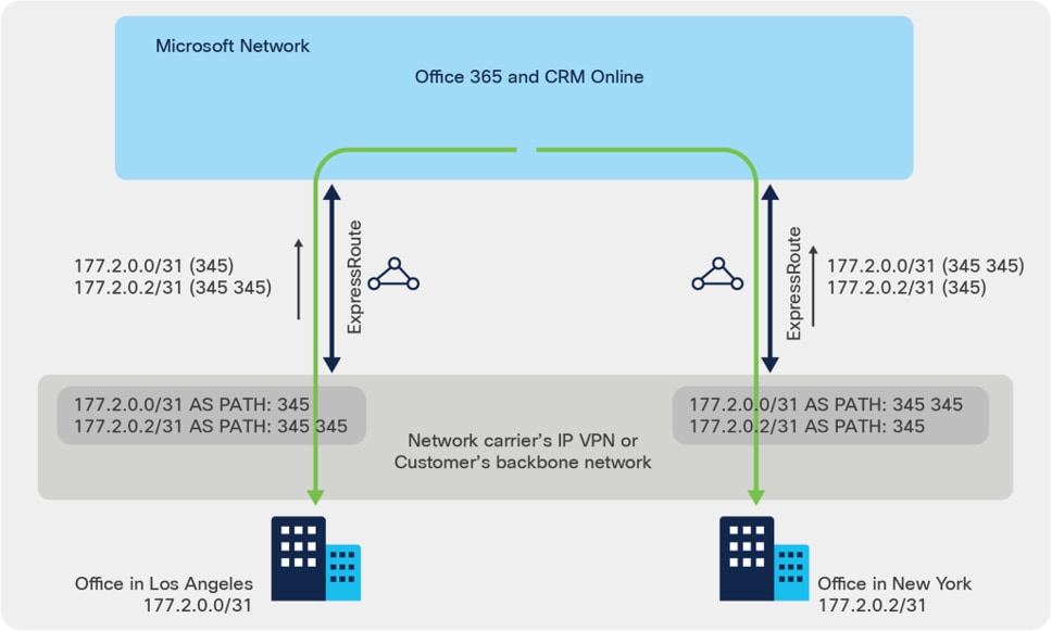
AS Path Prepending sample
You can lengthen the AS PATH for 177.2.0.0/31 in US East so that Microsoft will prefer the ExpressRoute circuit in US West for traffic destined for this prefix (as Microsoft network will think the path to this prefix is shorter in the west). Similarly, by lengthening the AS PATH for 177.2.0.2/31 in US West so that Microsoft will prefer the ExpressRoute circuit in US East.
#US West Catalyst 8500
!
router bgp 345
!
address-family ipv4 vrf 301
neighbor 198.137.97.26 route-map Prepend-USW out
network 177.2.0.0 mask 255.255.255.254
network 177.2.0.2 mask 255.255.255.254
!
ip prefix-list prefix_USW seq 10 permit 177.2.0.2/31
!
route-map Prepend-USW permit 10
match ip address prefix prefix_USW
set as-path prepend 345
!
route-map Prepend-USW permit 20
#US East Catalyst 8500
!
router bgp 345
!
address-family ipv4 vrf 301
neighbor 198.137.97.27 route-map Prepend-USE out
network 177.2.0.0 mask 255.255.255.254
network 177.2.0.2 mask 255.255.255.254
!
ip prefix-list prefix_USE seq 10 permit 177.2.0.0/31
!
route-map Prepend-USE permit 10
match ip address prefix prefix_USE
set as-path prepend 345
!
route-map Prepend-USE permit 20
Avoid Asymmetric Routing
Follow ER asymmetric routing solutions, in the example, if you want to use the Internet for authentication traffic and ExpressRoute for your mail traffic or other public services, you should not advertise your Active Directory Federation Services (AD FS) public IP addresses over ExpressRoute. This best practice can be enforced with an outbound route-map configuration:
router bgp 65021
!
address-family ipv4 vrf 301
neighbor 198.137.97.26 route-map AD_FS_Prefixes out
!
ip prefix-list AD_FS permit 121.10.0.1/32
!
route-map AD_FS_Prefixes deny 10
match ip address prefix-list AD_FS
route-map AD_FS_Prefixes permit 20
Bidirectional Forwarding Detection (BFD)
Enabling BFD is optional for failover between Primary and Secondary paths. However, ER supports BFD on both paths. Enable BFD on Azure peering sub-interfaces as shown below:
interface HundredGigE0/2/0.300
description Customer Private Peering to Azure
encapsulation dot1Q 300
vrf forwarding 300
ip address 192.168.30.17 255.255.255.252
ipv6 address FD:1:1:30FF::1/126
bfd interval 300 min_rx 300 multiplier 3
!
interface HundredGigE0/2/0.301
description Customer Microsoft Peering to Azure
encapsulation dot1Q 301
vrf forwarding 301
ip address 198.137.97.25 255.255.255.252
bfd interval 300 min_rx 300 multiplier 3
!
We also have to enable route fall-over in BGP configuration as shown below:
router bgp 65021
!
address-family ipv4 vrf 300
neighbor 192.168.30.18 fall-over bfd
exit-address-family
!
address-family ipv6 vrf 300
neighbor FD:1:1:30FF::2 fall-over bfd
exit-address-family
!
address-family ipv4 vrf 301
neighbor 198.137.97.26 fall-over bfd
exit-address-family
!
More details about BFD capabilities for ER can be found here.
As per Microsoft NAT for ExpressRoute, Microsoft expects to support bi-directional connectivity on the Microsoft peering. Traffic destined to Microsoft cloud services must be Source NAT’ed to valid public IP addresses before they enter the Microsoft network. You can use the sample configuration below to accomplish the task, it is using the MS peering sub-interface IP address as the NAT pool (198.137.97.25), so the returning traffic will be sent back to this router, un-NAT’ed before forwarded out of the DMZ VLAN.
interface HundredGigE0/1/0.301
description Customer DMZ VLAN for Microsoft Peering
encapsulation dot1Q 301
vrf forwarding 301
ip address 10.1.30.5 255.255.255.252
ip nat inside
!
interface HundredGigE0/2/0.301
description Customer Microsoft Peering to Azure
encapsulation dot1Q 30 second-dot1q 301
vrf forwarding 301
ip address 198.137.97.25 255.255.255.252
ip nat outside
!
ip route vrf 301 198.137.97.25 255.255.255.255 null0
!
ip nat pool Cust30_MSFT_Pool 198.137.97.25 198.137.97.25 netmask 255.255.255.252
!
ip nat inside source route-map Cust30_MSFT_sNAT pool Cust30_MSFT_Pool vrf 301 overload
!
ip access-list extended Local_BGP_301
remark deny BGP session from being NATed
permit tcp host 198.137.97.25 host 198.137.97.26 eq bgp
permit tcp host 198.137.97.26 host 198.137.97.25 eq bgp
!
access-list 10 permit 198.137.97.25
!
route-map Cust30_MSFT_sNAT deny 5
match ip address Local_BGP_301
!
route-map Cust30_MSFT_sNAT permit 10
description NAT any traffic in VRF 301 with NH 198.137.97.26 toward Microsoft Peering
match ip next-hop 10
It is your responsibility to ensure that the NAT IP pool advertised to Microsoft is NOT advertised to the Internet (even as a subnet of the Internet advertisement, they must be completely non-overlapping). Failure to meet this requirement may break connectivity to other Microsoft services.
NAT Common Best Practices
1. Set the NAT max-entries per system scale based on the Catalyst 8500 platform being used. Each Catalyst 8500 Series Edge Platform may have different NAT scale, please follow the relevant product datasheet.
ip nat translation max-entries 2000000
2. It is recommended to keep the default NAT timeout. If the user has specific needs to reduce the timer, for example the pools are being exhausted, then the user can refer to the sample commands below to make configuration changes:
The default NAT timeout values can be seen in show command
C8500#show platform hardware qfp active feature nat data time
Timeouts: default 86400; TCP 86400; TCP PPTP 86400; UDP 300; FINRST 60; SYN 60; DNS 60; ICMP 60; Skinny 60; ICMP error 60; ESP 300
To change the timeout values for example:
ip nat translation tcp-timeout 10800
3. If there is the requirement that both NAT and non-NAT’ed traffic must co-exist in the NAT outside interface, then use Gatekeeper to optimize system performance:
ip nat settings gatekeeper-size 65535
Route Redistribution into EIGRP
To redistribute routes from the Private and Microsoft BGP Peerings to EIGRP, add the following configuration
router eigrp 1
!
address-family ipv4 vrf 301
redistribute static route-map BGP_Private_to_App_EIGRP
redistribute bgp 65021 metric 1000000 100 255 1 1500
network 10.0.0.0 0.0.0.255
no auto-summary
autonomous-system 2
exit-address-family
!
address-family ipv4 vrf 300
redistribute bgp 65021 metric 1000000 100 255 1 1500
network 10.1.0.0 0.0.0.255
no auto-summary
autonomous-system 3
!
router bgp 65021
!
address-family ipv4 vrf 301
redistribute eigrp 2 route-map EIGRP_App_to_BGP
!
ip prefix-list BGP_Private_to_App_EIGRP seq 5 permit 10.3.0.0/23
!
ip access-list extended EIGRP_App_to_BGP
permit ip 10.0.0.0 0.0.0.255 any
!
route-map EIGRP_App_to_BGP permit 10
match ip address EIGRP_App_to_BGP
!
route-map BGP_Private_to_App_EIGRP permit 10
match ip address prefix-list BGP_Private_to_App_EIGRP
!
To NAT traffic from your corporate network, adjust the NAT configuration as follows
access-list 11 permit 10.1.0.0 0.0.0.255
route-map Cust30_MSFT_sNAT permit 10
description NAT any traffic in Corp_NET toward public peering
match ip address 11
Value-Added Feature Configurations
Flexible Netflow (FNF) is an embedded instrumentation capability within the Catalyst 8500 that characterizes network operation and IP traffic flows, which is critical for network availability, performance, and troubleshooting. The sample below shows how simple it can be to turn on FNF for Catalyst 8500.
flow exporter flow_expo
destination 10.10.10.9 vrf 301
transport udp 9996
!
flow monitor flow_mon
exporter flow_expo
record netflow-original
!
interface HundredGigE0/2/0.301
description Customer Primary Microsoft peering to Azure
ip flow monitor flow_mon input
ip flow monitor flow_mon output
!
interface HundredGigE0/2/0.300
description Customer Primary private peering to Azure
ip flow monitor flow_mon input
ip flow monitor flow_mon output
To be able to see bi-directional traffic in the Catalyst 8500 platform, you can turn on ingress NetFlow on all interfaces, or if you are only interested in the bi-directional traffic from and to ER, turn on ingress and egress NetFlow on ER. We recommend the use of full NetFlow instead of sampled NetFlow.
Follow ER QoS requirements, a 6-class QoS model, as shown in Table 3, can be implemented to fulfill the requirements while protecting the mission critical applications and network control traffic in the events of ER circuits congestion. Use the sample QoS configuration below to accomplish the task.
Table 3. 6-Class QoS Model
| Traffic Class |
DSCP Values |
Business workload |
Bandwidth % |
Congestion avoidance |
| Voice |
EF |
Skype / Lync voice |
10 (PQ) |
- |
| Video |
AF41 |
Interactive Video, VBSS |
30 remaining |
WRED |
| Network Control |
CS6 |
NET-CTRL* |
5 remaining |
- |
| Transactional Data |
AF21 |
App Sharing |
25 remaining |
WRED |
| Bulk Data |
AF11 |
File Transfer |
25 remaining |
WRED |
| Class-default |
Catch-all |
Catch-all |
15 remaining |
WRED |
Note: BGP is always marked as CS6 by Catalyst 8500, so it is protected in the NET-CTRL class.
class-map match-any VOICE
match dscp ef
class-map match-any VIDEO
match dscp af41
class-map match-any NETWORK-CONTROL
match dscp cs6
class-map match-any TRANSACTIONAL-DATA
match dscp af21
class-map match-any BULK-DATA
match dscp af11
!
! example of 500Mbps of ER circuit, adapt it to your circuit BW accordingly.
policy-map ER-500MBPS-POLICY
class class-default
shape average 500000000
service-policy ER
!
policy-map ER
class VOICE
priority level 1
police cir percent 10
class VIDEO
bandwidth remaining percent 30
random-detect
class NETWORK-CONTROL
bandwidth remaining percent 5
class TRANSACTIONAL-DATA
bandwidth remaining percent 25
random-detect
class BULK-DATA
bandwidth remaining percent 25
random-detect
class class-default
bandwidth remaining percent 15
random-detect
set dscp 0
! Microsoft require user to rewrite all other DSCP to 0 before sending the packets to ER
!
interface HundredGigE0/2/0.301
description Customer Primary Microsoft peering to Azure
service-policy output ER-500MBPS-POLICY
Advanced services configurations
Configure Application Visibility and Control (AVC)
If the DSCP values for applications above have not been marked properly or not preserved in your network before reaching the Catalyst 8500, use the Solution Reference Network Designs (SRND) policy model to simplify application classification in NBAR, and mark the application to the DSCP specified by Microsoft.
class-map match-all VOICE
match protocol attribute traffic-class voip-telephony
match protocol attribute business-relevance business-relevant
class-map match-all BROADCAST-VIDEO
match protocol attribute traffic-class broadcast-video
match protocol attribute business-relevance business-relevant
class-map match-all INTERACTIVE-VIDEO
match protocol attribute traffic-class real-time-interactive
match protocol attribute business-relevance business-relevant
class-map match-all MULTIMEDIA-CONFERENCING
match protocol attribute traffic-class multimedia-conferencing
match protocol attribute business-relevance business-relevant
class-map match-all MULTIMEDIA-STREAMING
match protocol attribute traffic-class multimedia-streaming
match protocol attribute business-relevance business-relevant
class-map match-all SIGNALING
match protocol attribute traffic-class signaling
match protocol attribute business-relevance business-relevant
class-map match-all NETWORK-CONTROL
match protocol attribute traffic-class network-control
match protocol attribute business-relevance business-relevant
class-map match-all NETWORK-MANAGEMENT
match protocol attribute traffic-class ops-admin-mgmt
match protocol attribute business-relevance business-relevant
class-map match-all TRANSACTIONAL-DATA
match protocol attribute traffic-class transactional-data
match protocol attribute business-relevance business-relevant
class-map match-all BULK-DATA
match protocol attribute traffic-class bulk-data
match protocol attribute business-relevance business-relevant
class-map match-all SCAVENGER
match protocol attribute business-relevance business-irrelevant
!
policy-map MARKING
class VOICE
set dscp ef
class BROADCAST-VIDEO
set dscp af41
class INTERACTIVE-VIDEO
set dscp af41
class MULTIMEDIA-CONFERENCING
set dscp af41
class MULTIMEDIA-STREAMING
set dscp af41
class SIGNALING
set dscp af41
class NETWORK-CONTROL
set dscp cs6
class NETWORK-MANAGEMENT
set dscp default
class TRANSACTIONAL-DATA
set dscp af21
class BULK-DATA
set dscp af11
class SCAVENGER
set dscp default
class class-default
set dscp default
!
interface HundredGigE0/1/0.301
description Customer DMZ VLAN for Microsoft Peering
service-policy input MARKING
!
A common use of IPsec VPN over ExpressRoute leverages the Cisco Catalyst 8000V Edge Software, Catalyst 8000V, deployed as an application VNet gateway in Azure to provide IPsec gateway for entire VNet. See Cisco Catalyst 8000V Edge Software Data Sheet. The Catalyst 8500 connecting to ER is the ideal gateway for the IPsec tunnel termination in Enterprise network as the platform delivers embedded hardware acceleration for IPsec VPN. For details on Catalyst 8500 system IPsec throughput, refer to the relevant product datasheet.
The Cisco Catalyst 8000V shares same IOS XE code base as that of Catalyst 8500 Series in virtual form factor. They inherit the same IOS XE software architecture, support the same CLIs and feature sets of IPsec VPN.
Once you have deployed Catalyst 8000V on Azure, you would configure the IPsec VPN on the Catalyst 8000V by using the step-by-step procedure outlined as per the sample:
crypto isakmp policy 200
encryption aes
authentication pre-share
group 2
lifetime 28800
!
crypto isakmp key cisco123 address 0.0.0.0
crypto isakmp keepalive 10 10
!
crypto ipsec security-association replay window-size 1024
!
crypto ipsec transform-set c8kv esp-aes esp-sha-hmac
mode tunnel
crypto ipsec df-bit clear
!
crypto ipsec profile c8kv
set transform-set c8kv
!
interface Tunnel1
ip address 192.168.100.2 255.255.255.252
tunnel source GigabitEthernet1
tunnel mode ipsec ipv4
tunnel destination 172.16.0.1
tunnel protection ipsec profile c8kv
You should have the IPsec tunnel peer configuration on the Catalyst 8500 enabled as per the sample:
crypto isakmp policy 200
encryption aes
authentication pre-share
group 2
lifetime 28800
!
crypto isakmp key cisco123 address 0.0.0.0
crypto isakmp keepalive 10 10
!
crypto ipsec security-association replay window-size 1024
!
crypto ipsec transform-set c8500 esp-aes esp-sha-hmac
mode tunnel
crypto ipsec df-bit clear
!
crypto ipsec profile c8500
set transform-set c8500
!
interface Tunnel1
ip vrf forwarding 301
ip address 192.168.100.1 255.255.255.252
tunnel source HundredGigE0/2/0.301
tunnel mode ipsec ipv4
tunnel destination 10.0.0.4
tunnel protection ipsec profile c8500
While there are steps to verify ExpressRoute connectivity with Microsoft, there are also verification steps can be performed on Catalyst 8500 platforms and in the customer on-premises network.
Use the following commands to verify the Microsoft peering and Private BGP peering are established and Up
C8500-01#show ip bgp vpnv4 vrf 301 neighbors 198.137.97.26
BGP neighbor is 198.137.97.26, vrf 301, remote AS 12076, external link
BGP version 4, remote router ID 40.90.1.160
BGP state = Established, up for 3w3d
Last read 00:00:14, last write 00:00:07, hold time is 90, keepalive interval is 30 seconds
Last update received: 3w3d
Neighbor sessions:
1 active, is not multisession capable (disabled)
Neighbor capabilities:
Route refresh: advertised and received(new)
Four-octets ASN Capability: advertised and received
Address family IPv4 Unicast: advertised and received
Enhanced Refresh Capability: advertised
Multisession Capability:
Stateful switchover support enabled: NO for session 1
Message statistics:
InQ depth is 0
OutQ depth is 0
Sent Rcvd
Opens: 1 1
Notifications: 0 0
Updates: 5 1
Keepalives: 78325 73785
Route Refresh: 0 0
Total: 78331 73787
Do log neighbor state changes (via global configuration)
Default minimum time between advertisement runs is 0 seconds
For address family: VPNv4 Unicast
Translates address family IPv4 Unicast for VRF 301
Session: 198.137.97.26
BGP table version 1086, neighbor version 1086/0
Output queue size : 0
Index 8, Advertise bit 1
8 update-group member
Inbound soft reconfiguration allowed
NEXT_HOP is always this router for eBGP paths
Slow-peer detection is disabled
Slow-peer split-update-group dynamic is disabled
Sent Rcvd
Prefix activity: ---- ----
Prefixes Current: 3 4 (Consumes 544 bytes)
Prefixes Total: 4 4
Implicit Withdraw: 0 0
Explicit Withdraw: 1 0
Used as bestpath: n/a 4
Used as multipath: n/a 0
Used as secondary: n/a 0
Outbound Inbound
Local Policy Denied Prefixes: -------- -------
Bestpath from this peer: 4 n/a
Total: 4 0
Number of NLRIs in the update sent: max 2, min 0
Current session network count peaked at 4 entries at 23:55:12 Jul 15 2021 UTC (3w3d ago)
Highest network count observed at 177 entries at 20:05:53 Jul 15 2021 UTC (3w4d ago)
Last detected as dynamic slow peer: never
Dynamic slow peer recovered: never
Refresh Epoch: 1
Last Sent Refresh Start-of-rib: never
Last Sent Refresh End-of-rib: never
Last Received Refresh Start-of-rib: never
Last Received Refresh End-of-rib: never
Sent Rcvd
Refresh activity: ---- ----
Refresh Start-of-RIB 0 0
Refresh End-of-RIB 0 0
Address tracking is enabled, the RIB does have a route to 198.137.97.26
Route to peer address reachability Up: 2; Down: 1
Last notification 3w3d
Connections established 4; dropped 3
Last reset 3w3d, due to Active open failed
External BGP neighbor configured for connected checks (single-hop no-disable-connected-check)
Interface associated: HundredGigE0/2/0.301 (peering address in same link)
Transport(tcp) path-mtu-discovery is enabled
Graceful-Restart is disabled
SSO is disabled
Connection state is ESTAB, I/O status: 1, unread input bytes: 0
Connection is ECN Disabled, Minimum incoming TTL 0, Outgoing TTL 1
Local host: 198.137.97.25, Local port: 179
Foreign host: 198.137.97.26, Foreign port: 62134
Connection tableid (VRF): 2
Maximum output segment queue size: 50
Enqueued packets for retransmit: 0, input: 0 mis-ordered: 0 (0 bytes)
Event Timers (current time is 0x814995B9):
Timer Starts Wakeups Next
Retrans 78334 5 0x0
TimeWait 0 0 0x0
AckHold 73786 72431 0x0
SendWnd 0 0 0x0
KeepAlive 0 0 0x0
GiveUp 0 0 0x0
PmtuAger 0 0 0x0
DeadWait 0 0 0x0
Linger 0 0 0x0
ProcessQ 0 0 0x0
iss: 3000770835 snduna: 3002259278 sndnxt: 3002259278
irs: 625343006 rcvnxt: 626745041
sndwnd: 16384 scale: 0 maxrcvwnd: 16384
rcvwnd: 15909 scale: 0 delrcvwnd: 475
SRTT: 1000 ms, RTTO: 1003 ms, RTV: 3 ms, KRTT: 0 ms
minRTT: 0 ms, maxRTT: 1000 ms, ACK hold: 200 ms
uptime: -2139875890 ms, Sent idletime: 10042 ms, Receive idletime: 9933 ms
Status Flags: passive open, gen tcbs
Option Flags: VRF id set, nagle, path mtu capable
IP Precedence value : 6
Datagrams (max data segment is 1460 bytes):
Rcvd: 151210 (out of order: 0), with data: 73786, total data bytes: 1402034
Sent: 151858 (retransmit: 5, fastretransmit: 0, partialack: 0, Second Congestion: 0), with data: 78330, total data bytes: 1488442
Packets received in fast path: 0, fast processed: 0, slow path: 0
fast lock acquisition failures: 0, slow path: 0
TCP Semaphore 0x7F856F8F9648 FREE
C8500-01#
C8500-01#show ip bgp vpnv4 vrf 300 neighbors 192.168.30.18
BGP neighbor is 192.168.30.18, vrf 300, remote AS 12076, external link
BGP version 4, remote router ID 192.168.30.18
BGP state = Established, up for 3w3d
Last read 00:00:27, last write 00:00:18, hold time is 90, keepalive interval is 30 seconds
Last update received: 3w3d
Neighbor sessions:
1 active, is not multisession capable (disabled)
Neighbor capabilities:
Route refresh: advertised and received(new)
Four-octets ASN Capability: advertised and received
Address family IPv4 Unicast: advertised and received
Enhanced Refresh Capability: advertised
Multisession Capability:
Stateful switchover support enabled: NO for session 1
Message statistics:
InQ depth is 0
OutQ depth is 0
Sent Rcvd
Opens: 1 1
Notifications: 0 0
Updates: 2 3
Keepalives: 78333 73794
Route Refresh: 0 0
Total: 78336 73798
Do log neighbor state changes (via global configuration)
Default minimum time between advertisement runs is 0 seconds
For address family: VPNv4 Unicast
Translates address family IPv4 Unicast for VRF 300
Session: 192.168.30.18
BGP table version 1086, neighbor version 1086/0
Output queue size : 0
Index 7, Advertise bit 0
7 update-group member
Inbound soft reconfiguration allowed
NEXT_HOP is always this router for eBGP paths
Outbound path policy configured
Route map for outgoing advertisements is only-advertise-private
Slow-peer detection is disabled
Slow-peer split-update-group dynamic is disabled
Sent Rcvd
Prefix activity: ---- ----
Prefixes Current: 2 1 (Consumes 136 bytes)
Prefixes Total: 2 2
Implicit Withdraw: 0 0
Explicit Withdraw: 0 1
Used as bestpath: n/a 1
Used as multipath: n/a 0
Used as secondary: n/a 0
Outbound Inbound
Local Policy Denied Prefixes: -------- -------
Bestpath from this peer: 2 n/a
Other Policies: 4 n/a
Total: 6 0
Number of NLRIs in the update sent: max 2, min 0
Current session network count peaked at 1 entries at 23:55:10 Jul 15 2021 UTC (3w3d ago)
Highest network count observed at 1 entries at 20:05:23 Jul 15 2021 UTC (3w4d ago)
Last detected as dynamic slow peer: never
Dynamic slow peer recovered: never
Refresh Epoch: 1
Last Sent Refresh Start-of-rib: never
Last Sent Refresh End-of-rib: never
Last Received Refresh Start-of-rib: never
Last Received Refresh End-of-rib: never
Sent Rcvd
Refresh activity: ---- ----
Refresh Start-of-RIB 0 0
Refresh End-of-RIB 0 0
Address tracking is enabled, the RIB does have a route to 192.168.30.18
Route to peer address reachability Up: 2; Down: 1
Last notification 3w3d
Connections established 4; dropped 3
Last reset 3w3d, due to Active open failed
External BGP neighbor configured for connected checks (single-hop no-disable-connected-check)
Interface associated: HundredGigE0/2/0.300 (peering address in same link)
Transport(tcp) path-mtu-discovery is enabled
Graceful-Restart is disabled
SSO is disabled
Connection state is ESTAB, I/O status: 1, unread input bytes: 0
Connection is ECN Disabled, Minimum incoming TTL 0, Outgoing TTL 1
Local host: 192.168.30.17, Local port: 52761
Foreign host: 192.168.30.18, Foreign port: 179
Connection tableid (VRF): 2
Maximum output segment queue size: 50
Enqueued packets for retransmit: 0, input: 0 mis-ordered: 0 (0 bytes)
Event Timers (current time is 0x814DD469):
Timer Starts Wakeups Next
Retrans 78342 6 0x0
TimeWait 0 0 0x0
AckHold 73799 72427 0x0
SendWnd 0 0 0x0
KeepAlive 0 0 0x0
GiveUp 0 0 0x0
PmtuAger 2148077 2148076 0x814DD6AF
DeadWait 0 0 0x0
Linger 0 0 0x0
ProcessQ 0 0 0x0
iss: 1625504237 snduna: 1626992703 sndnxt: 1626992703
irs: 3231832257 rcvnxt: 3233234537
sndwnd: 16384 scale: 0 maxrcvwnd: 16384
rcvwnd: 15681 scale: 0 delrcvwnd: 703
SRTT: 1000 ms, RTTO: 1003 ms, RTV: 3 ms, KRTT: 0 ms
minRTT: 0 ms, maxRTT: 1000 ms, ACK hold: 200 ms
uptime: -2139583365 ms, Sent idletime: 716 ms, Receive idletime: 916 ms
Status Flags: active open
Option Flags: VRF id set, nagle, path mtu capable
IP Precedence value : 6
Datagrams (max data segment is 1460 bytes):
Rcvd: 151065 (out of order: 0), with data: 73798, total data bytes: 1402279
Sent: 151871 (retransmit: 6, fastretransmit: 0, partialack: 0, Second Congestion: 0), with data: 78336, total data bytes: 1488465
Packets received in fast path: 0, fast processed: 0, slow path: 0
fast lock acquisition failures: 0, slow path: 0
TCP Semaphore 0x7F856F8F9168 FREE
C8500-01#
BGP session is essential to maintain ER connectivity. To protect BGP packets in the Catalyst 8500 punt path and mitigate potential DDoS attacks, it is recommended you implement Control Plane Policing. More details for CoPP capabilities can be found here.
Verify ExpressRoute connectivity
Follow the procedure here to verify ExpressRoute connectivity. The ExpressRoute circuit can be validated by using the Azure portal “Home > ExpressRoute circuits” and looking at the “Essentials” field. If you see “Circuit status” is Enabled, then the ExpressRoute Circuit is up on the Microsoft side. For Provider enabled ER circuits, the “Provider status” as Provisioned, then the circuit is up on the service provider side also. Figure 6 shows a sample output for ExpressRoute Direct circuit that also has Peering location information.
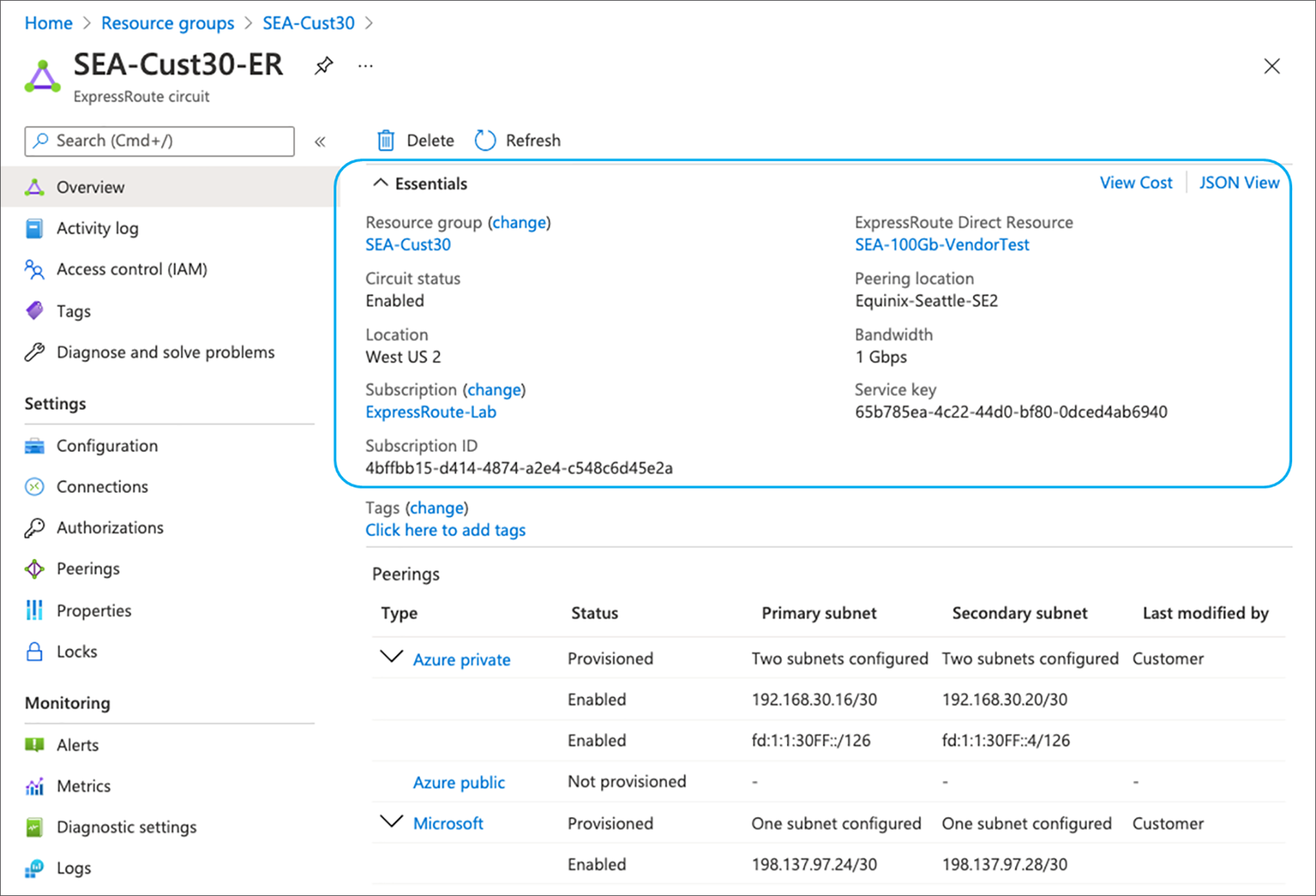
Verify ExpressRoute Circuit Status in Azure Portal Snapshot (ER Direct Model)
Following is a sample for service provider ER circuit. Here the important things to verify is ‘Circuit status’ as ‘Enabled’ and ‘Provider status’ as ‘Provisioned’
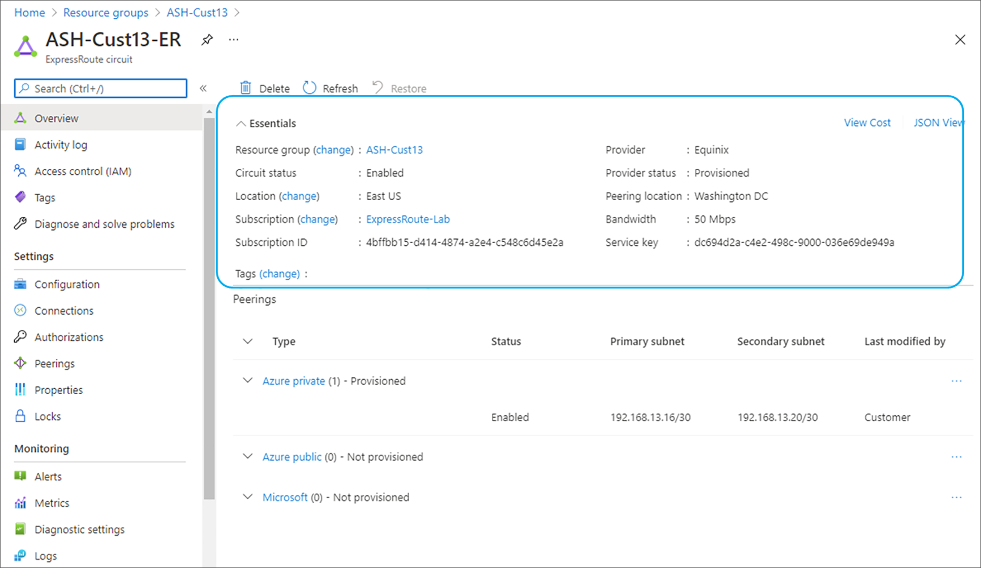
Verify ExpressRoute Circuit Status in Azure Portal Snapshot (ER Service Provider Model)
To further validate that the circuit is up from the customer side, click “Home > ExpressRoute circuit > Azure Private/Microsoft Private > Get route table summary” to see if your sub-interface networks are reachable, as shown in Figure 8 and 9 respectively. This output gets real time routing table information from Microsoft peering router.
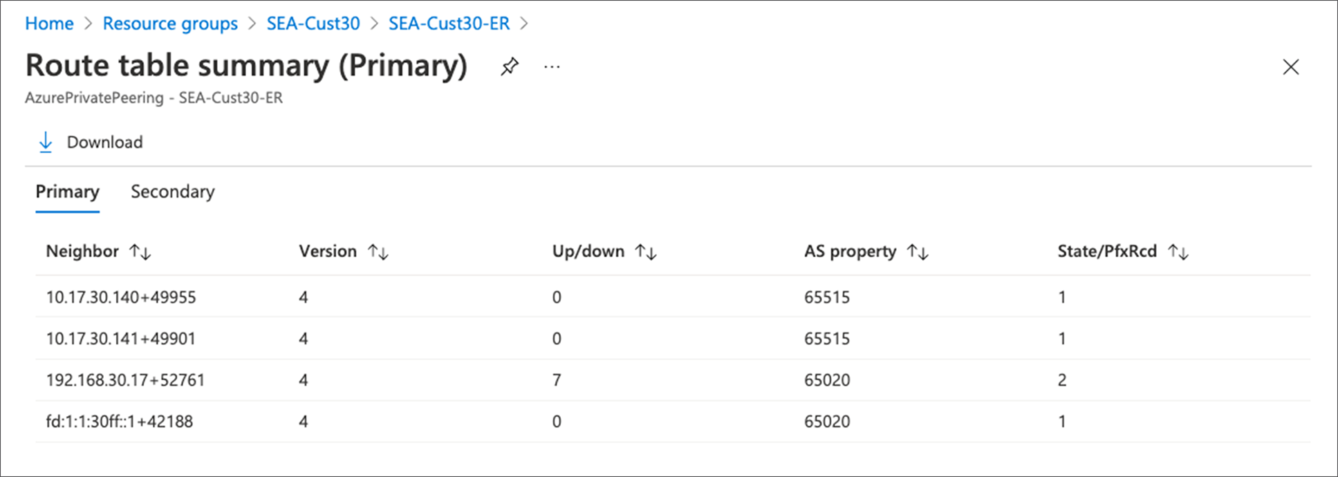
Verify Private Peering Customer Networks are Reachable in Azure Portal Snapshot
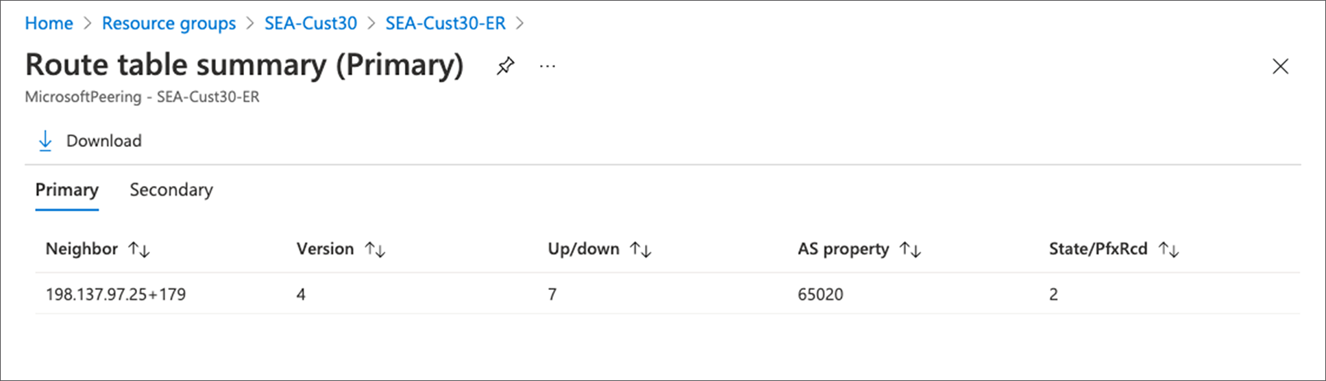
Verify Microsoft Peering Customer Networks are Reachable in Azure Portal Snapshot
Verify MACsec MKA Session is ‘Secured’
MACsec MKA session status can be verified using following CLI for ‘Secured’ status:
C8500-01#show mka sessions
Total MKA Sessions....... 1
Secured Sessions... 1
Pending Sessions... 0
====================================================================================================
Interface Local-TxSCI Policy-Name Inherited Key-Server
Port-ID Peer-RxSCI MACsec-Peers Status CKN
====================================================================================================
Hu0/2/0 549f.c625.8320/0019 xpn-p1 NO YES
25 44ec.ceec.04db/0001 1 Secured 1234
C8500-01#
Verify MACsec Encryption Statistics
If MACsec is enabled for ExpressRoute Direct connectivity, the encryption and decryption statistics can be verified using following CLI.
C8500-01#show macsec statistics interface HundredGigE 0/2/0
MACsec Statistics for HundredGigE0/2/0
SecY Counters
Ingress Untag Pkts: 0
Ingress No Tag Pkts: 0
Ingress Bad Tag Pkts: 0
Ingress Unknown SCI Pkts: 0
Ingress No SCI Pkts: 0
Ingress Overrun Pkts: 0
Ingress Validated Octets: 0
Ingress Decrypted Octets: 155939761
Egress Untag Pkts: 0
Egress Too Long Pkts: 0
Egress Protected Octets: 0
Egress Encrypted Octets: 166077086
Controlled Port Counters
IF In Octets: 187722145
IF In Packets: 2648532
IF In Discard: 0
IF In Errors: 0
IF Out Octets: 198008522
IF Out Packets: 2660953
IF Out Errors: 0
Transmit SC Counters (SCI: 549FC62583200019)
Out Pkts Protected: 0
Out Pkts Encrypted: 2660953
Transmit SA Counters (AN 0)
Out Pkts Protected: 0
Out Pkts Encrypted: 2660953
Receive SA Counters (SCI: 44ECCEEC04DB0001 AN 0)
In Pkts Unchecked: 0
In Pkts Delayed: 0
In Pkts OK: 2648532
In Pkts Invalid: 0
In Pkts Not Valid: 0
In Pkts Not using SA: 0
In Pkts Unused SA: 0
In Pkts Late: 0
C8500-01#
Following is a sample output for MKA policy configuration for 100 Gbps interface using GCM-AES-XPN-256 cipher.
C8500-01#show mka policy xpn-p1
MKA Policy Summary...
Codes : CO - Confidentiality Offset, ICVIND - Include ICV-Indicator,
SAKR OLPL - SAK-Rekey On-Live-Peer-Loss,
DP - Delay Protect, KS Prio - Key Server Priority
Policy KS DP CO SAKR ICVIND Cipher Interfaces
Name Prio OLPL Suite(s) Applied
=============================================================================
xpn-p1 0 FALSE 0 FALSE TRUE GCM-AES-XPN-256 Hu0/2/0
C8500-01#
Following is an example of 10 Gbps interface using GCM-AES-256 cipher.
C8500-01#show mka policy non-xpn-p2
MKA Policy Summary...
Codes : CO - Confidentiality Offset, ICVIND - Include ICV-Indicator,
SAKR OLPL - SAK-Rekey On-Live-Peer-Loss,
DP - Delay Protect, KS Prio - Key Server Priority
Policy KS DP CO SAKR ICVIND Cipher Interfaces
Name Prio OLPL Suite(s) Applied
=============================================================================
non-xpn-p2 0 FALSE 0 FALSE TRUE GCM-AES-256 Te0/1/0
C8500-01#
Verify NAT Translation Entries and Pool
Follow NAT monitoring and Maintaining guide to verify NAT translation entries are set up properly if NAT is enabled on Catalyst 8500 platforms.
C8500-01#show ip nat translation
To monitor NAT pool status:
C8500-01#show platform software nat fp active pool
The Catalyst 8500 exports the NetFlow cache entries directly from the QuantumFlow Processor data plane ASIC to the external collector via in-band interface. Do NOT connect the collector on the management interface (GigabitEthernet0). Use the following command to verify the flow monitor is exporting data to the exporters.
C8500-01#show flow monitor flow_mon
Use the Top N talkers capability, which facilitates real-time traffic analysis of the most traffic volume consumers.
C8500-01#show flow monitor flow_mon cache sort counter packets top 3 format table
Note: Catalyst 8500 does not support aggregate flows in Top N talkers.
Catalyst 8500 Proactive system monitoring
Proactive monitoring system resources allows you to detect potential problems before they happen, thus avoiding outages. IOS XE provides a system wide platform resource summary command- show platform resources. It covers most of the critical system resources on Catalyst 8500 platforms.
C8500-01#show platform resources
**State Acronym: H - Healthy, W - Warning, C - Critical
Resource Usage Max Warning Critical State
-------------------------------------------------------------------------------------------------
RP0 (ok, active) H
Control Processor 1.06% 100% 80% 90% H
DRAM 3585MB(23%) 15484MB 88% 93% H
bootflash 1560MB(6%) 25725MB 88% 93% H
harddisk 0MB(0%) 0MB 88% 93% H
ESP0(ok, active) H
QFP H
TCAM 8cells(0%) 1048576cells 65% 85% H
DRAM 371733KB(1%) 20971520KB 85% 95% H
IRAM 16597KB(12%) 131072KB 85% 95% H
CPU Utilization 0.00% 100% 90% 95% H
Crypto Utilization 0.00% 100% 90% 95% H
Pkt Buf Mem (0) 1152KB(0%) 164864KB 85% 95% H
Pkt Buf CBlk (0) 14544KB(1%) 986112KB 85% 95% H
C8500-01#
The system resources to be consumed by each of the features discussed in the configuration guide are listed in Table 4.
Table 4. Feature to system resources consumption
| Features |
System Resources Consumed |
| BGP |
IOS memory/CPU, RP memory/CPU |
| FIB |
IOS memory/CPU, RP memory/CPU |
| NAT |
QFP, resource DRAM, TCAM |
| Netflow |
QFP, resource DRAM |
| QoS |
QFP, TCAM |
| AVC |
QFP, resource DRAM, TCAM |
| IPsec |
IOS memory/CPU, RP memory/CPU, QFP, Crypto Assist, TCAM |
The best practice is that during steady state the system should have minimum 25% of IOS memory, RP memory, and resource DRAM available to accommodate potential network churning and reconvergence events; otherwise, you should plan to upgrade system memory to higher value.
Catalyst 8500 Series Edge Platforms inherit IOS XE code from ASR 1000 Platforms. This enables same look and feel for configuration and serviceability of the platforms. Existing ASR 1000 documentation can be suitably referred for understanding specific topics on Catalyst 8500 platforms as well.
Note: ASR 1000 Platforms are also capable of supporting the ExpressRoute use-case discussed in this document. For MACsec only 100 Gbps Ethernet Port Adaptors (EPA) are supported with ASR 1000 platforms.
Please refer to the following documentation for platform architecture, packet flow, feature configuration guide and datasheet:
● Catalyst 8500 Series Edge Platforms Architecture White Paper
● Catalyst 8500 Hardware Installation Guide
● Catalyst 8500 Series Edge Platforms Data Sheet
● Catalyst 8500 Series Edge Platforms Ordering Guide
● Flexible Netflow Configuration Guide
● Security for VPNs with IPsec
● IPsec Virtual Tunnel Interface
● ASR1000-X Router Hardware Installation Guide
● ASR1000-HX Router Hardware Installation Guide
Refer to the following documentation for common error messages and troubleshooting notes:
● Troubleshooting of ASR1k Made Easy
● ASR1000 Troubleshooting TechNotes
● ASR1000 Error and System Messages
● Embedded Packet Capture for IOS-XE