Cisco Unified Wireless Network Solution Guide
Available Languages
Bias-Free Language
The documentation set for this product strives to use bias-free language. For the purposes of this documentation set, bias-free is defined as language that does not imply discrimination based on age, disability, gender, racial identity, ethnic identity, sexual orientation, socioeconomic status, and intersectionality. Exceptions may be present in the documentation due to language that is hardcoded in the user interfaces of the product software, language used based on RFP documentation, or language that is used by a referenced third-party product. Learn more about how Cisco is using Inclusive Language.
Cisco wireless network solution overview
Built from the ground up for intent-based networking and Cisco DNA Center, the Cisco Catalyst™ 9800 Series Wireless Controllers bring together Cisco IOS® XE Software and Cisco RF excellence to create a best-in-class wireless experience for your evolving and growing organization.
These controllers also support the newest Wi-Fi 6E Cisco Catalyst 9100 Access Points.
This document primarily focuses on the Cisco® wireless on-premises solution, managed by Cisco DNA Center.
The Cisco Catalyst wireless network solution offers secure, scalable, cost-effective wireless LANs for business-critical mobility. It is the industry’s only unified wired and wireless solution to cost-effectively address the deployment, management, security, and network optimization of a Wireless LAN (WLAN) in enterprises.
This powerful indoor and outdoor solution combines the best elements of wired and wireless networking to deliver high-performance, manageable, and secure WLANs with a low total cost of ownership.
1. Next-generation wireless: An introduction
Mobile users require the same accessibility, security, Quality of Service (QoS), and high availability enjoyed by wired users. Whether users are at work, at home, or on the road, locally or internationally, there is a need to connect. The technological challenges are apparent, but mobility plays a role for everyone. Companies are deriving business value from mobile and wireless solutions. What was once a vertical market technology is now mainstream and is an essential tool in getting access to voice, real-time information, and critical applications such as email and calendar, enterprise databases, supply chain management, sales force automation, and customer relationship management.
Benefits of the Catalyst wireless infrastructure
Benefits achieved by WLANs include:
● Mobility within buildings or campus: Facilitates implementation of applications that require an always-on network and that tend to involve movement within a campus environment.
● Convenience: Simplifies networking for large, open areas where people congregate.
● Flexibility: Allows work to be done at the most appropriate or convenient place, rather than where a cable drop terminates. Getting the work done is what is important, not where you are.
● Easier setup of temporary spaces: Promotes quick network setup of meeting rooms, war rooms, or brainstorming rooms tailored to variations in the number of participants.
● Lower cabling costs: Reduces the requirement for contingency cable plant installation because the WLAN can be employed to fill the gaps.
● Easier adds, moves, and changes and lower support and maintenance costs: Enables easier setup of temporary networks, easing migration issues and costly last-minute fixes.
● Improved efficiency: Studies show that WLAN users are connected to the network 15 percent longer per day than hard-wired users.
● Productivity gains: Promotes easier access to network connectivity, resulting in better use of business productivity tools. Productivity studies show a 22 percent increase for WLAN users.
● Easier collaboration: Facilitates access to collaboration tools from any location, such as meeting rooms; files can be shared on the spot and requests for information handled immediately.
● More efficient use of office space: Allows greater flexibility for accommodating groups, such as large team meetings.
● Fewer errors: Data can be entered directly into systems as it is being collected, rather than when network access is available.
● Improved efficiency, performance, and security for enterprise partners and guests: Enables implementation of guest access networks.
● Improved business resilience: Increased mobility of the workforce allows rapid redeployment to other locations with WLANs.
The core components of the Cisco wireless solutions include:
● Cisco Access Points (APs)
● Cisco Catalyst 9800 Series Wireless Controllers (WLC)
● Cisco DNA Center
● Cisco Prime® Infrastructure
● Cisco Identity Services Engine
● Cisco Spaces
For more information about the Cisco wireless network, see the Cisco Wireless and Mobility page at https://www.cisco.com/c/en/us/products/wireless/index.html.
2. Cisco wireless technology and architecture
The Internet Engineering Task Force (IETF) Control and Provisioning of Wireless Access Points (CAPWAP) protocol is the underlying protocol used in the Cisco WLAN architecture. CAPWAP provides the configuration and management of APs and WLANs in addition to encapsulation and forwarding of WLAN client traffic between an AP and a WLAN Controller (WLC).
CAPWAP brings additional security with Datagram Transport Layer Security (DTLS) for both management and client traffic. CAPWAP uses the User Datagram Protocol (UDP) and can operate over either IPv4 or IPv6. Table 1 lists the protocol and port implemented for each CAPWAP version.
Table 1. Ports and protocols
| IP version |
Protocol number |
Destination |
Description |
| Version 4 |
17 (UDP) |
5246 |
CAPWAPv4 control channel |
| 17 (UDP) |
5247 |
CAPWAPv4 data channel |
|
| Version 6 |
136 (UDP Lite) |
5246 |
CAPWAPv6 control channel |
| 136 (UDP Lite) |
5247 |
CAPWAPv6 data channel |
Cisco recommends the following guidelines when implementing CAPWAP:
● IP addressing: APs must be assigned a static or dynamic IPv4 or IPv6 address to be able to successfully discover and communicate with a WLC.
● Firewall rules and Access Control Lists (ACLs): All firewall rules and ACLs defined on devices placed between the APs and WLCs must be configured to permit the CAPWAP protocol.
● IPv6 deployments: At least one WLC should be configured for both IPv4 and IPv6 to support APs with older firmware that does not support IPv6.
CAPWAP functions
The CAPWAP AP handles the following functions:
● Frame exchange handshake between a client and AP.
● Transmission of beacon frames.
● Buffering and transmission of frames for clients in power save mode.
● Response to probe request frames from clients; the probe requests are also sent to the WLC for processing.
● Forwarding notification of received probe requests to the WLC.
● Provision of real-time signal quality information to the switch with every received frame.
● Monitoring each of the radio channels for noise, interference, and other WLANs.
● Monitoring for the presence of other APs.
● Encryption and decryption of 802.11 frames.
● Data handling in centralized deployments.
● QoS handling.
WLC functions
The Cisco WLC handles the following functions:
● 802.11 authentication.
● 802.11 association and reassociation (mobility) in centralized deployment (local mode).
● 802.11 frame translation and bridging.
● 802.1X, Extensible Authentication Protocol (EAP), and RADIUS processing.
● Termination of 802.11 traffic on a wired interface, except in the case of Cisco FlexConnect® Aps.
● Mobility.
● Data handling in centralized deployments.
● QoS handling.
Security and encryption
Communication between the Cisco WLC and APs is secured and encrypted. CAPWAP control and data packets exchanged between an AP and a WLC use DTLS. DTLS is an IETF protocol based on Transport Layer Security (TLS). All Cisco access points and controllers are shipped with a Manufacturing Installed Certificate (MIC), which is used by an AP and WLC by default for mutual authentication and encryption key generation. Cisco also supports Locally Significant Certificates (LSC) to provide additional security for enterprises that wish to issue certificates from their own Certificate Authority (CA).
By default, DTLS uses the RSA 128-bit Advanced Encryption Standard/Secure Hash Algorithm 2 (AES/SHA-2) cipher suite, which is globally defined using the #ap dtls-cipher-suite command. Alternative ciphers include 256-bit AES with SHA-1 or SHA-256. DTLS is enabled by default to secure the CAPWAP control channel but is disabled by default for the data channel. No DTLS license is required to secure the control channel. All CAPWAP management and control traffic exchanged between an AP and WLC is encrypted and secured by default to provide control plane privacy and prevent Man-In-the-Middle (MIM) attacks.
CAPWAP data encryption is optional and is enabled per AP. Data encryption requires a DTLS license to be installed on the WLC prior to being enabled on an AP. When enabled, all WLAN client traffic is encrypted at the AP before being forwarded to the WLC and vice versa. DTLS data encryption is automatically enabled for teleworker APs but is disabled by default for all other APs. Most APs are deployed in a secure network where data encryption is not necessary. In contrast, traffic exchanged between a teleworker AP and WLC is forwarded over an unsecured public network, where data encryption is important.
Discovery process and provisioning
In a CAPWAP environment, an AP discovers a WLC by using a CAPWAP discovery mechanism and then sends the WLC a CAPWAP join request. When an AP joins a WLC, the WLC manages its configuration, firmware, control transactions, and data transactions. A CAPWAP AP must discover and join a WLC before it can become an active part of the Cisco wireless network.
Each Cisco AP supports the following discovery processes:
Step 1. Broadcast discovery: The AP sends a CAPWAP discovery message to the IPv4 broadcast address (255.255.255.255). Any WLC connected to the same VLAN will see the discovery message and will in turn reply with a unicast IPv4 discovery response.
Step 2. Multicast discovery: The AP sends a CAPWAP discovery message to the multicast group address for all controllers (FF01::18C). Any WLC connected to the same VLAN will see the discovery message and will in turn reply with an IPv6 discovery response.
Step 3. Locally stored controller IPv4 or IPv6 address discovery: If the AP was previously associated to a WLC, the IPv4 or IPv6 addresses of the primary, secondary, and tertiary controllers are stored in the AP’s nonvolatile memory (NVRAM). This process of storing controller IPv4 or IPv6 addresses on an AP for later deployment is called priming the access point.
Step 4. Dynamic Host Configuration Protocol (DHCP) discovery: DHCPv4 and/or DHCPv6 servers are configured to advertise WLC IP addresses to APs using vendor-specific options:
◦ DHCPv4 discovery using option 43: DHCPv4 servers use option 43 to provide one or more WLC management IPv4 addresses to the AP. Option 43 values are supplied to an AP in the DHCPv4 offer and acknowledgment packets.
◦ DHCPv6 discovery using option 52: DHCPv6 servers use option 52 to provide one or more WLC management IPv6 addresses to the AP. Option 52 values are supplied to an AP in the DHCPv6 advertise and reply packets.
Step 5. DNS discovery: The AP sends a DNS query to the DNSv4 and/or DNSv6 servers to attempt to resolve cisco-capwap-controller.localdomain (where localdomain is the AP domain name provided by DHCP).
Step 6. The Plug and Play (PnP) server provides staging parameters to an AP before it joins a controller. Using this staging configuration, the AP receives the runtime configuration when it joins the controller.
The AP PnP feature enables the PnP server to provide all tag-related information as part of the preconfigured information to the AP and, in turn, to the controller.
You can upload a configuration to the PnP server in either TXT or JSON format and add the AP details. The AP details are then mapped with the details in the TXT or JSON configuration file. While the AP is being provisioned from the PnP server, it acquires the details of this configuration. Based on the configuration details, the AP then joins the corresponding controller with the tag details.
Step 7. If, after steps 1 through 6, no CAPWAP discovery response is received, the AP resets and restarts the discovery process.
Cisco Catalyst 9800 Series Wireless Controllers support Cisco access points in Local (centralized and Software-Defined Access [SD-Access] deployment), FlexConnect, Bridge, Flex+Bridge, Sniffer, and Monitor modes.
The Cisco Catalyst 9800 Series configuration data model is based on design principles of reusability, simplified provisioning, enhanced flexibility, and modularization to help in network management, as they scale and simplify the management of dynamically changing business and IT requirements.
This model enables the client/AP devices to derive their configurations from profiles that are contained within tags. APs can be mapped to the tags either statically or as part of the rule engine that runs on the controller and comes into effect during the AP join process. Configuration objects are modularized as objects, which helps in the reusability of configurations. In addition, a flat, tag-based configuration model eliminates the complexities associated with inheritance and container-based grouping, leading to a simpler and more flexible configuration that can ease change management.
If you are familiar with AireOS WLCs, you are aware of APs and FlexConnect groups. Those groups allow you to control what capabilities (for example, which WLANs or RF profiles) are available for each AP, based on its AP group association.
On Catalyst 9800 Series WLCs, tags are used to control the features that are available for each AP. Tags are assigned to every AP, and inside every tag you can find all the settings that were applied to the AP.
There are three types of tags:
● Policy tag
● Site tag
● RF tag
A policy tag is the link between a WLAN profile (Service Set Identifier [SSID]) and a policy profile.
● Policy profile: Inside a policy profile you can specify a virtual LAN (VLAN) ID, whether traffic is central or local switching, mobility anchors, QoS, and timers, among other settings.
● SSID: Inside an SSID you can specify the WLAN name, a security type for the WLAN, and advanced protocols such as 802.11k, among other settings.
A site tag defines whether the APs are in Local mode or FlexConnect mode. Other AP modes, such as Sniffer, Sensor, Monitor, and Bridge, can be configured directly on the AP. The site tag also contains the AP Join profile and Flex profile that are applied to the AP.
● AP Join profile: Inside an AP Join profile you can specify settings such as CAPWAP timers, remote access to APs (via Telnet or Secure Shell [SSH]), backup controller configuration, and others.
● Flex profile: On a Flex profile, you have settings such as Address Resolution Protocol (ARP) caching, VLAN/ACL mapping, and so on.
Inside an RF tag you can either select any RF profile or select to use the Global RF configuration.
● 2.4-GHz profile: Allows you to define specific data rates to be used, Transmit Power Control (TPC) settings, Dynamic Channel Assignment (DCA), and some other Radio Resource Management (RRM) settings for the 2.4-GHz band.
● 5-GHz profile: Allows you to define specific data rates to be used, TPC settings, DCA, and some other RRM settings for the 5-GHz band.
By default, the APs get assigned the default tags (default Policy, Site, and RF tags), and the default tags get assigned the default profiles (default Policy AP Join, and Flex profiles).
For detailed information on configuration model and guidelines, please visit the Cisco Catalyst 9800 Wireless Controller Series Web UI Deployment Guide at https://www.cisco.com/c/dam/en/us/td/docs/wireless/controller/9800/17-4/deployment-guide/c9800-webui-dg.pdf.
The Wireless Management Interface (WMI) is the mandatory Layer 3 interface on the Catalyst 9800 Series. It is used for all communications between the controller and access points. It is also used for all CAPWAP or inter-controller mobility messaging and tunneling traffic.
WMI is also the default interface for in-band management and connectivity to enterprise services, such as authentication, authorization, and accounting (AAA), syslog, Simple Network Management Protocol (SNMP), and so on. You can use the WMI IP address to remotely connect to the device using SSH or Telnet, or access the GUI using HTTP or HTTPs by entering the WMI IP address of the controller in the address field of your browser.
The WMI is a Layer 3 interface and can be configured with an IPv4 address or IPv6 address or by using a dual-stack configuration.
It is always recommended to use a wireless management VLAN and configure WMI as a Switched VLAN Interface (SVI). If the uplink port or port-channel to the next-hop switch is configured as a dot1q trunk, the wireless management VLAN would be one of the allowed tagged VLANs on the trunk.
For centrally switched traffic, it is mandatory to configure a Layer 2 VLAN mapped to the SSID, but the corresponding Layer 3 interface (SVI) is optional. This is different from AireOS, in which a dynamic interface (Layer 3 interface and related IP address) is required. The recommendation for the Catalyst 9800 Series is not to configure an SVI for a client VLAN unless:
● You need to run DHCP relay on the Catalyst 9800, either because this function cannot be configured on the next-hop Layer 3 switch (the default gateway for that VLAN) or because you want to add option 82 information in the DHCP relayed packet.
● You want to enable the mDNS gateway and you are running code before 17.9.1; in 17.9.1 and higher, the mDNS gateway feature no longer needs a client SVI interface.
This section describes the basic information necessary to understand RF considerations in planning for various WLAN environments. The topics covered include:
● Regulatory domains and RF considerations
● IEEE 802.11 standards.
● RF spectrum implementations of 802.11b/g/n/ax (2.4 GHz) and 802.11a/n/ac/ax (5 GHz) and 6 GHz.
● Planning for RF deployment.
● Radio Resource Management (RRM) algorithms.
● Antenna choices.
The Federal Communications Commission (FCC), European Telecommunications Standards Institute (ETSI), and other regulatory bodies regulate the use of wireless devices in three main bands (frequency ranges) allocated for unlicensed Industrial, Scientific, and Medical (ISM) usage.
The ISM bands are designated as the:
● 2.4-GHz band (IEEE 802.11b/g/n/ax): 2.4 to 2.4835 GHz. The 2.4-GHz band provides the most coverage but transmits data at slower speeds.
● 5-GHz band (IEEE 802.11a/n/ac/ax): The 5-GHz band provides less coverage but transmits data at faster speeds.
● 6-GHz band (IEEE 802.11ax): The 6-GHz band, introduced with the new Wi-Fi 6E standard, provides the least coverage but transmits data at the fastest speeds of the three frequencies.
Separation of physical groups of clients is performed using different frequency assignments, or channels. For an AP operating on a given channel, there is a finite amount of airtime available, and every client connecting to an AP shares the airtime that the AP channel has to offer. The more clients that are actively using an AP, the less airtime each individual client will get. Supporting a higher data rate for one or more clients (for more efficient use of airtime) will increase available airtime for all clients and result in higher potential bandwidth to the individual user.
All clients on a given channel share a common collision domain that extends to other APs operating on the same channel, regardless of whose network they ultimately belong to. This means that other clients and access points using the same channel, and able to hear one another, share the available airtime. Each additional AP added to a channel brings with it management overhead on the air. The effect of this additional management traffic further reduces the total amount of airtime available for each user and constrains performance. In short:
Bandwidth = Airtime x Data rate.
If you require more bandwidth than can be served from a single AP (for example, if you have many users in a small area), multiple APs will be required. When implemented on nonoverlapping channels, each AP provides an isolated chunk of airtime over its coverage area. APs that are on the same channel must be kept out of range of one another. This is what Cisco’s RRM manages for you—the power and the channel selection to coordinate multiple APs and neighbors for optimal performance.
Channel assignment and reuse for the network is a big factor in determining the airtime efficiency and ultimately the bandwidth that can be delivered to the clients. When two APs can hear one another on the same channel, the result can be co-channel interference unless the overlapping basic service set (BSS) is managed carefully. Whether co-channel interference is the result of your own APs or of your AP and a neighbor doesn’t matter– either way the APs must share the channel. To produce a good physical design, four things must be considered:
● AP placement
● AP operating band (2.4 GHz or 5 GHz or 6 GHz)
● AP channels
● AP power levels
The goal in a good design is to produce even wireless coverage (similar conditions end to end) with minimal co-channel interference, maximizing the available potential bandwidth for the client devices.
Cisco’s RRM calculates and assigns the best channels and power combinations using measured, over-the-air metrics. Over-the-air observations include Wi-Fi networks operating within the infrastructure as well as existing external users, both Wi-Fi and non-Wi-Fi, of the spectrum. RRM will mitigate co-channel assignments and balance power, but if there are no open channels available, or if the APs are simply too close together, the only choice remaining is to share the channel with an existing user. This happens in congested environments, and two different networks may have to share the same bandwidth. If one is not busy, the other may use all the bandwidth. If both become busy, they will share the bandwidth 50/50 due to 802.11’s contention mechanisms (“listen before talk”) that are designed to ensure fair access.
Devices that operate in unlicensed bands do not require a formal licensing process on the part of the end user. However, equipment designed and built for operating 802.11 in the ISM bands is obligated to follow the government regulations for the region it is to be used in. “Unlicensed” does not mean without rules. Cisco wireless equipment is designed and certified to operate and meet the regulatory requirements for specific regions. Regulatory designations are included in the part numbers for pre-provisioned regions.
The end user bears responsibility for correct implementation and for ensuring that the correct equipment is used for the specified region. Your Cisco sales team can guide you in making a selection.
The regulatory agencies in different regions of the world monitor the unlicensed bands according to their individual criteria. WLAN devices must comply with the specifications of the relevant governing regulatory body. Although the regulatory requirements do not affect the interoperability of IEEE 802.11a/b/g/n/ac/ax-compliant products, the regulatory agencies do set certain criteria in the product implementation. For example, the RF emission requirements for WLAN devices are designed to minimize the amount of interference any radio (not just Wi-Fi) can generate or receive from any other radio within a certain proximity. It is the responsibility of the WLAN vendor to obtain product certification from the relevant regulatory body. And it is the responsibility of the installer to ensure that the resulting installation does not exceed those requirements. We recommend and certify the use of antennas and radio combinations that meet regulatory requirements.
Besides following the requirements of the regulatory agencies, Cisco helps ensure interoperability with other vendors through various Wi-Fi Alliance (WFA) certification programs (www.wi-fi.org).
The 2.4-GHz band regulations of 802.11b/g/n/ax have been relatively constant, given the length of time they have been in operation. The FCC (U.S) allows for 11 channels, ETSI (and most other parts of the world) allows for up to 13 channels, and Japan allows up to 14 channels but requires a special license and operating modes to operate in channel 14.
Countries that adhere to the 5-GHz band regulations of 802.11a/n/ac/ax are more diverse in the channels they allow and their rules for operation. In addition, the advancement of 802.11ax regulatory domains around the world has opened spectrum around 6 GHz for unlicensed communications such as Wi-Fi. As one example, the FCC has proposed opening 1.2 GHz of spectrum between 5.925 GHz and 7.125 GHz, which is more than the total amount of spectrum used for Wi-Fi today.
This new spectrum will be extremely valuable, as the current 2.4-GHz and 5-GHz bands used for Wi-Fi are crowded and heavily used. Additionally, the 6-GHz band will allow only devices supporting the latest 802.11ax Wi-Fi standard. In other words, only HE (High Efficiency) devices will be supported, not HT (High Throughput), VHT (Very High Throughput), or older legacy devices. This will result in 6-GHz Wi-Fi networks being more performant, since the network won’t be slowed down by legacy Wi-Fi devices as the 2.4- and 5-GHz bands are today.
These frequency bands and their associated protocols can and do change as the technology evolves and regulatory rules change. Regulatory certifications and allowed frequencies and channels for all Cisco APs are documented in their individual data sheets.
Should I design for 2.4 GHz, 5 GHz, or 6 GHz?
Wi-Fi is a relatively mature technology today. While there are still places where Wi-Fi is not present, it is hard to find any place where there are people that doesn’t have some signal coverage. A good way to look at this is: the more independent neighbors you have, the more Wi-Fi interference you either already have or possibly will have. Interference is often at its worst in multi-dwelling facilities, where many disparate company offices share a single building and spectrum.
This issue is of critical importance, since Wi-Fi passes through walls and floors and must operate and accept all interference from other Wi-Fi and non-Wi-Fi devices alike. What this means is that to the degree that your network devices can hear other networks, they will share the available airtime with those other networks. If you and your neighbor are both heavy users, you will both get less bandwidth than the connection speeds would suggest in the areas that your networks overlap. For both networks, waiting on the other to access the channel will cost time (and less time on the air leads to less throughput).
Using 2.4 GHz in a congested metropolitan city, multi-dwelling facility, or shopping mall will produce variable success at best, and at worst can be unusable. Best practices recommend three nonoverlapping channels in most of the world.
Use 2.4 GHz for a larger coverage range and in deployments where the use of legacy and Internet of Things (IoT) devices is prevalent.
Table 2. Comparison of 2.4 GHz, 5 GHz, and 6 GHz
| 2.4 GHz overview |
5 GHz overview |
6 GHz overview |
| Pros: Larger coverage area, better at penetrating solid objects |
Pros: Higher data rate, less prone to interference, usually fewer devices using this frequency |
Pros: Higher number of channel bonding, wider range, advanced security |
| Cons: Lower data rate, more prone to interference, usually more devices using this frequency |
Cons: Smaller coverage area (except 802.11ac), worse at penetrating solid objects |
Cons: Smaller coverage area, reduced cell size, and challenges similar to 5 GHz with regard to penetration |
If an application is critical to business operations and requires higher speeds, plan on using 5 GHz. Once upon a time this was more difficult to do, as 5-GHz devices were less prevalent. This is not the case today, as most manufacturers are focusing on 802.11ax and Wi-Fi 6E as the standards for their products.
The 6-GHz band is newly certified and is exclusive to devices that support Wi-Fi 6E. This means that on 6 GHz, the Wi-Fi network doesn’t need to slow down to accommodate legacy devices. The 6-GHz band also supports almost twice as many channels as 5 GHz. Fewer devices, more spectrum, and more bandwidth mean less interference and network congestion.
What protocols should I enable?
There are multiple protocol standards available in the 802.11 standard. In fact, everything that has been ratified since 1999 is still required for WFA certification and is present in all hardware that supports the band it belongs to. That doesn’t mean that you need to use it, though. The choices you make in deciding which protocols to support (and which not to) can have a big impact on your network’s efficiency.
By efficiency we mean the use of airtime. The faster a station can get onto and off the air, the more airtime will be available for other stations. 802.11b was one the first protocols implemented in 2.4 GHz. Today it is truly a unique example among all other Wi-Fi protocols, as both the coding and modulation methods are completely different from every other protocol that has been ratified since.
802.11n and 802.11ac also provide for block ACK, or block acknowledgments, which allow for higher efficiency gains by allowing a large block of packets to be acknowledged all at one. The legacy protocols all send a packet and get a response, one by one. This adds a considerable number of frames to the transaction for reliability that is largely no longer needed with modern standards.
Now, with 802.11ax, we get the capacity, efficiency, coverage, and performance required by users today in the most demanding Wi-Fi environments. The 802.11ax standard emphasizes quality connectivity in locations with hundreds or thousands of connected devices, such as stadiums and other public venues, as well as corporate networks using time-sensitive, high-bandwidth applications. With 11ax, devices meet the highest standards for security and interoperability and enable lower battery consumption, making it a solid choice for any environment, including the IoT.
Cisco WLCs have several options available for implementing the most popular and necessary speeds. The various network types and decision points are detailed later in this document to ensure that you understand the need to implement a well-tuned network from the start.
What are DFS channels, and should I use them?
Many of the channels available in 5 GHz are known as Dynamic Frequency Selection, or DFS, channels. Along with Transmit Power Control (TPC), DFS defines coexistence mitigations (that is, detect and avoid) for radar while operating in the UNII-2 and UNII-2e bands (channels 52 to 144). These mechanisms are detailed in an amendment to the 802.11 standard.
The 802.11h standard was crafted to solve problems such as interference with satellites and radar, which also legally use the 5-GHz band as primary users. A primary user has priority over the frequency range of UNII-2 and UNII-2e. It is Wi-Fi’s job, as a condition of using these frequencies, to not interfere with any primary users. While this standard was introduced primarily to address European regulations, it is used by many other regions of the world today to achieve the same goals of enabling more operational 5-GHz spectrum for Wi-Fi.
In 2004, the U.S. added channels 100 to 140 in the UNII-2e (“e” stands for extended) band, with rules requiring 802.11h certification, which allow us to peacefully coexist with primary licensed users of the 5-GHz frequencies in this range. For Europe these channels represent most of their available 5-GHz spectrum today. Before the rules and mechanisms were worked out, Europe was limited to only 4 channels in 5 GHz. At the same time in the U.S., we had UNII-1, 2, and 3, for a total of 13 channels.
For equipment that does not interfere with licensed band users, the requirements are straightforward:
● The Wi-Fi equipment must be able to detect radar and satellite emissions.
● Before using a channel in this range, a “channel primary” (an infrastructure AP) must first listen for 60 seconds and determine that the channel is clear of radar.
● If a radar signal is detected, the Wi-Fi channel primary, and all the clients associated to it, have to abandon the channel immediately and not return to it for 30 minutes, at which time it can be cleared again for Wi-Fi use if no radar emissions are detected.
U-NII-2e channels got a bad name early in 2004 in the U.S. among network administrators. Clients were slow to adopt the new rules initially, so using these channels in the infrastructure meant that you could (and some did) inadvertently configure a channel that some clients wouldn’t be able to use, creating a coverage hole for that client type. There were also many undue concerns about DFS operations in a production network. The concern was that if DFS detected radar, a channel change followed by waiting a full minute before resuming transmissions was viewed as disruptive. However, the behavior is not disruptive, as RRM initially places the AP into a non-DFS channel. The channel is blocked for 30 minutes and then made available again to RRM by means of background scanning to clear the required listening time. Once the channel is available, we can choose to use it or remain on the current channel, depending on which is better for the clients.
It has been a decade since the addition of these channels and 802.11h logic. In Europe, DFS is and has been making 5-GHz Wi-Fi possible and even enabling it to flourish. Client vendors vary; the majority support the DFS channels just fine, as there is no additional logic required by the client.
If you are within 5 miles of an airport or shipping port and have concerns, evaluate by monitoring the channel range with Cisco APs. Cisco leads the industry in certified hardware models and function for DFS operation and flexibility. Monitoring the channels will alert you to any potential interference and will identify the affected channels.
A site survey is an important tool. It will tell you who is operating around you—and, more importantly, where and how much they interfere with your intended coverage zones. It also allows identification of mounting locations, existing cable plants, infrastructure requirements, and architectural oddities and yields a plan to get the coverage your application requires. Because RF interacts with the physical world around it, and all buildings and offices are different, so is each network to a degree. Unfortunately, there is no “one size fits all” for Wi-Fi. There are recommendations by deployment type, and it is possible to generalize what you are likely to encounter. If you have not done a site survey in a while, keep in mind what has changed since the last one before you decide against it:
● The protocols and radio technology.
● How the users will use the network (likely everyone, and for almost anything).
● How many clients the network supports (likely a lot more users; count as at least two devices per user these days, and many have more).
● The primary use of the network (very likely changed since the initial plan and implementation).
While early WLAN designs focused on coverage to get a few casual users signal everywhere, today’s WLAN designs are more focused on capacity, as the number of users has increased and what we are demanding of the network has gone up exponentially. A capacity design requires more APs in closer proximity to manage the number of users who are sharing the bandwidth of the cell. Increasing placement density should have a plan.
If you decide to conduct your own survey and plan, tools are important. There are multiple free tools online and available as downloads. However, if you want professional results, you need professional tools.
The free tools can provide simple solutions for smaller, less complex projects. But if you are looking to provide ubiquitous multimedia coverage in a multifloor or multibuilding campus, you need a good tool to balance the elements that will be required for success. Planning tools have evolved with the radio technologies and applications in use today. A familiarity with the design elements and applications is required to produce a good plan.
Cisco Prime Infrastructure has a planning tool built in, and you can import and export maps and plans between Cisco Prime and many top survey and planning applications, such as Ekahau ESS and AirMagnet Pro Planner and Survey.
Similarly, the Ekahau Pro tool allows you to create the complete network plan for your enterprise, including floor layout, AP locations, and obstacles. After creating the floor layout, you can export the simulated network plan and the real-world site survey data into a format that Cisco DNA Center can use. You can import the Ekahau project file into Cisco DNA Center for further planning.
Ekahau Pro version 10.2 allows you to automatically create the site hierarchy, save it as a project file, and import it into Cisco DNA Center.
For more on site surveys, visit Understand Site Survey Guidelines for WLAN Deployment at https://www.cisco.com/c/en/us/support/docs/wireless/5500-series-wireless-controllers/116057-site-survey-guidelines-wlan-00.html.
Having a site survey done for 802.11ax now will yield good information that can be used again and again as the network grows and continues to evolve. Whether this is something that you should contract out in part or handle yourself depends on the size of your project and your level of knowledge with regard to Wi-Fi.
Different deployment types for WLAN coverage
The amount of WLAN coverage you plan for in the design of your wireless network depends largely on the usage and density of clients you require. With limited exceptions, all designs should be deployed to minimize retransmission and data rate shifting while supporting good client roaming and throughput. Wireless networks can be deployed for data-only, voice, video, and location-aware services or, more frequently these days, a combination of all of these. The difference between these application types is minimal today, with the requirements of each largely describing good, solid, capacity-based coverage. Location-aware services add some AP placement criteria for good location triangulation and guidelines on hyperlocation technologies. Real-time multimedia (voice and video) applications have different latency requirements for two-way live implementations. But by and large, all describe a minimum coverage level needed to make the application viable for the number of users you expect in any given area.
For most campuses and enterprise installations, coverage and capacity are the primary concerns, and these are easily achievable. High-density client implementations or high-interference locations such as shopping malls or apartment buildings may require additional equipment such as external antennas to properly implement the network to scale. The sections that follow provide in-depth information on application-specific guidelines, recommendations, and configurations.
Most application-specific coverage guidelines describe the signal level or coverage required at the cell edge for good operation as a design recommendation. This is generally a negative Received Signal Strength Indication (RSSI) value such as -67 dBm. It’s important to understand that this number assumes a good signal-to-noise ratio (SNR) of 25 dB with a noise floor of 92 dBm. If the noise floor is higher than 92 dBm, 67 dBm may not be enough signal to support the minimum data rates required for the application to perform its function.
For location-aware services, deploying a network to a specification on 67 dBm is fine; what matters to location-aware applications is how the network hears the client, not how the client hears network. For location-aware services we need to hear the client at three APs or more at a level of at least 75 dBm for it to be part of the calculation. (72 dBm is the recommended design minimum.)
Clients are a big consideration when planning coverage. They come in all shapes and sizes these days, and as a result individual implementations can and do vary widely on their opinion of the strength of a given RF signal. For instance, the laptop you are using for surveying may show 67 dBm at the cell edge, the tablet might show 68 dBm, and the smartphone may show 70 dBm. These are all very different opinions and affect roaming and data rates that everyone will use. Overbuilding to accommodate these varying opinions will help assure a trouble-free installation. When taking measurements, using the device that will support the application is the best approach. Understanding that your smartphones are generally 5 dB off from your survey tool will let you develop good rules for design (such as adding or subtracting 5 dB to whatever the reading is from your survey tool). Then test and tune the resulting implementation.
High-density client coverage requirements
High client density can be defined as any environment with a high number of concentrated clients (1 client at least every 1.5 square meters), such as a conference room, classroom, lecture hall, auditorium, sports arena, or conference hall. The concepts stay the same regardless of the size of the challenge. The tools required and methods employed increase in complexity with the complexity (size) of the challenge.
What needs to and can be managed remains largely remains the same. Two things that remain true about a high-density client environment are:
● You cannot serve more bandwidth than you have available.
● Capitalizing on ALL the potential bandwidth is a matter of proper sizing and an efficient and tuned design.
Visit the Wireless High Client Density Design Guide for more information: https://www.cisco.com/c/en/us/td/docs/wireless/controller/technotes/8-7/b_wireless_high_client_density_design_guide.html.
Roaming and voice coverage requirements
Client roaming enables a client to move from one AP coverage zone into another AP coverage zone, minimizing interruption in service and coverage. This is the very essence of mobility. There are many factors that must be considered for roaming to be effective. For instance, how the client transitions its association and authentication from one AP to another must be considered as well as the time it takes to do so. An often-overlooked aspect is the network design itself. For a client to roam, there must be something to roam to. Cells must overlap with good coverage for a client to gracefully leave coverage of one cell and establish an association within coverage on another without delay. Too little overlap encourages “sticky” clients, meaning a client holding on to an AP well after it moves into the coverage area of another AP.
When designing for network coverage, consider the amount of overlap needed in the required signal range you are getting. Overlap should be 10% to 15% (15% to 20% for voice) of the total coverage area. Voice is particularly sensitive, as the conversation is in real time, and any coverage lapse will result in broken audio or potentially a lost call. An easy way to calculate overlap is to measure the distance from the AP to the point where you reach 67 dBm, then multiply that distance by 1.4 for 15% to 20% or by 1.3 for 10% to 15%, and that’s where your next AP goes.
Data rates also matter, as the usable cell size increases with lower data rates and decreases with higher data rates. Higher data rates require a higher SNR, and since the noise floor is theoretically constant, the closer the client is to the signal (the AP) the higher the SNR and the resulting data rate will be. We can enforce minimum data rates in configuration, and when a client can no longer support a given data rate, it will have to move.
A good physical design enables and supports roaming at the physical layer. Only the client decides when to roam, though, and the decisions it makes are based on the client’s observation of the network. There have been multiple amendments to the 802.11 specification specifically to help clients make better decisions based on network infrastructure observations. See the following guides for additional information on roaming and configuring Cisco hardware and software to enable good roaming transitions. Cisco supports 802.11r, 802.11k, and 802.11v, which assist capable clients in making good decisions and afford some control from the infrastructure to enforce design goals.
Ascertain Methods for 802.11 WLAN and Fast-Secure Roaming on Cisco Unified Wireless Network: https://www.cisco.com/c/en/us/support/docs/wireless-mobility/wireless-lan-wlan/116493-technote-technology-00.html.
802.11r BSS Fast Transition chapter of Catalyst 9800 Series Wireless Controller Software Configuration Guide: https://www.cisco.com/c/en/us/td/docs/wireless/controller/9800/config-guide/b_wl_16_10_cg/802-11r-bss-fast-transition.html.
Assisted Roaming (802.11k) chapter of Catalyst 9800 Series Wireless Controller Software Configuration Guide: https://www.cisco.com/c/en/us/td/docs/wireless/controller/9800/config-guide/b_wl_16_10_cg/assisted-roaming.html.
Location-aware coverage requirements
Location–aware deployments differ slightly from other types in that the goal of the installation is to provide good location resolution of clients, tags, and IoT sensors in the context of where they are on a given map. We derive this information in its most basic form from client RSSI readings obtained by multiple APs (a minimum of three APs is required to triangulate on the client’s position). The pattern that you choose for deploying your APs can have a big effect on the network’s ability to “locate” a client accurately.
For good location resolution, the APs are laid out in a staggered pattern, with APs defining the borders and corners. It is possible to get coverage using APs in a straight line down the middle of both sections; however, this would not provide enough APs to hear and triangulate on clients in all locations (remember, we need three). Coverage and capacity requirements for this floor require many APs to start with, so it is quite likely, given your coverage requirements, that you already have what is needed to perform good location calculations.
Deployment Best Practices: Location-Aware WLAN Design Considerations (https://www.cisco.com/en/US/docs/solutions/Enterprise/Mobility/emob30dg/Locatn.html#wp1040131) is a must-read chapter and still quite relevant, as the physical requirements for the design have not changed.
Flexible Radio Assignment (FRA) radios and coverage requirements
A recent Cisco innovation, the flexible radio AP models (Cisco Aironet® 2800, 3800, and 4800 Series and Cisco Catalyst 9120, 9130, 9124, 9136, and 9162, 9164, and 9166 Series) access points were designed specifically to solve some of the challenges presented by traditional dual-band radios. Each of the coverage scenarios described above has improved solutions when using these radios.
High density is impacted by the flexible radio AP’s dual 5-GHz ability, allowing for two independent 5-GHz channels from a single AP.
● The internal antenna model will be implemented as a macro/micro cell, or as a cell within a cell. The FRA RRM logic also provides logic for balancing clients between the two cells. This will double the bandwidth within the cell boundary.
● The “E” model or external antenna model can provide two 5-GHz macro cells, which allows the implementation to gain two 5-GHz cells using the same Ethernet cable and switch port. A second antenna, and a DART connector to attach it, are required, but both together are far cheaper than an additional AP and switch ports, and you would still need the antenna. This is particularly beneficial for updating an existing high-density coverage area, as very often you can reuse everything except the APs and dramatically increase the capacity in 5 GHz.
Voice coverage: These APs participate in the FRA RRM algorithm, which will calculate the correct 2.4 vs. 5 GHz balance and prevent overutilization of 2.4-GHz radios. In general, voice should be implemented in 5 GHz only, and FRA helps there significantly by enabling a higher density of 5 GHz while right-sizing the density of 2.4-GHz radios. Protections are built in against being overly dense in 5 GHz by allowing the flexible interface to be placed in a monitoring role (both bands), which increases the Resolution of RF Metrics (RRM observations, location information).
Table 3. AP models and types of hardware managed by FRA
| AP model |
FRA radios |
Functions |
| Cisco Aironet 2800 Series Access Points |
2.4/5 XOR |
2.4-GHz and 5-GHz or dual 5-GHz operations |
| Cisco Aironet 3800 Series Access Points |
2.4/5 XOR |
2.4-GHz and 5-GHz or dual 5-GHz operations |
| Cisco Aironet 4800 Series Access Points |
2.4/5 XOR |
2.4-GHz and 5-GHz or dual 5-GHz operations |
| Cisco Catalyst 9120 Series Access Points |
2.4/5 XOR |
2.4-GHz and 5-GHz or dual 5-GHz operations |
| Cisco Catalyst 9130 Series Access Points |
5-GHz Tri-Radio |
2.4-GHz 4x4 and single 5-GHz 8x8, or 2.4-GHz 4x4 and dual 5-GHz 4x4 |
| Cisco Catalyst Wireless 9166 Access Points |
5/6-GHz XOR |
2.4-GHz 4x4 and dual 5-GHz 4x4, or 5-GHz 4x4 and 6-GHz 4x4 |
Power level and antenna choice
Power level and antenna design choice go together to determine AP placement and coverage results. Together, these two variables determine where and how powerful the RF is in any given place in the environment. Along with choosing the correct antenna to produce the required coverage area, we recommend that you use RRM to control the power level and provide the optimal channel and power plan. For more information, see the RRM section later in this document.
An antenna gives the wireless system three fundamental properties:
● Gain: A measure of increase in power introduced by the antenna over a theoretical (isotropic) antenna that transmits the RF energy equally in all directions. Gain also affects received signals and can assist weaker client devices by increasing the signal presented to the receiver.
◦ Front-to-back ratio, or FTB: The opposite of gain is signal rejection. The opposite direction of the gain in an antenna is less sensitive than the focus of the antenna, and this property can be used to isolate your cell from unwanted signals behind the antenna, for instance.
● Direction: The shape of the antenna transmission pattern. Different antenna types have different radiation patterns that provide various amounts of gain in different directions. A highly directional antenna will produce a very tight beam pattern. Outside of the area of focus, signals erode quickly, which allows more cells to be placed in the same physical space without interference.
● Polarization: Indicates the direction of the electric field. An RF signal has both an electric field and a magnetic field. If the electric field is orientated vertically, the wave will have a vertical polarization.
A good analogy for how an antenna works is the reflector in a flashlight. The reflector concentrates and intensifies the light beam in a particular direction, like what a parabolic dish antenna does to an RF source in a radio system. The antenna, however, is both the ears and the mouth of the AP, so the characteristics of a given antenna work for both transmit and receive. Many different antenna designs exist to serve different purposes. Some of the more familiar designs appear in Figure 1.
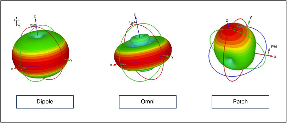
Antenna design types
Gain and direction mandate range, speed, and reliability, while polarization affects reliability and isolation of noise.
For more information on antenna selection, see the Cisco Aironet and Catalyst Antennas and Accessories Reference Guide at https://www.cisco.com/c/en/us/products/collateral/wireless/aironet-antennas-accessories/product_data_sheet09186a008008883b.html.
Omnidirectional antennas
Omnidirectional antennas have a different radiation pattern compared to isotropic antennas; the isotropic antenna is theoretical, and therefore all physical antennas are different from the isotropic antenna. Any change in shape of the radiation pattern of an isotropic antenna is experienced as gain and increases directionality. The dipole omnidirectional antenna features a radiation pattern that is nearly symmetrical about a 360-degree axis in the horizontal plane and 75 degrees in the vertical plane (assuming the dipole antenna is standing vertically). The radiation pattern of an omnidirectional antenna generally resembles a doughnut in shape and hence is directional. The higher the rated gain in dBi of a given omnidirectional antenna, the more focused the energy is (generally in the vertical plane) and the more directional it becomes. See the comparison between an isotropic and omnidirectional dipole antenna in Figure 2 below. Note that the views are from the side.
Omnidirectional antennas work well and are easy to implement – to a point. If you are faced with increasing the density of APs to accommodate more capacity requirements, you will see increasing channel utilization from self-interference. This happens because the antenna pattern is designed for maximum coverage. 3000 to 6000 square feet (280 to 560 square meters) of coverage per AP can be managed with the internal antennas. If your coverage requirements are at the minimum or denser than this, you should consider directional antennas.
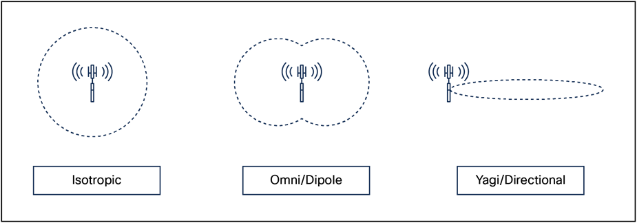
Isotropic vs. omnidirectional vs. directional antenna
Directional antennas
A directional antenna differs from an omnidirectional antenna in that the energy is focused in a particular way to achieve different coverage goals. Most people assume that a directional antenna is used specifically for gain – to increase power. While directional antennas can be used for that reason and can achieve greater distances, they are more often used in Wi-Fi to control the size (and shape) of the transmit and receive cell.
For current Cisco indoor APs (Catalyst 9100), the antenna selections are all dual band (each antenna covers 2.4 and 5 GHz) patch-type antennas designed for different coverage distances. The three most popular are shown below.
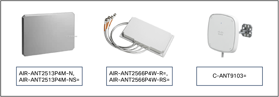
Directional antenna options
Each antenna is designed for a specific purpose. When selecting an antenna, one of the factors to consider is the beamwidth. Beamwidth describes the coverage area of an antenna; however, it does not describe how hard or soft the edge of that coverage is. For that you need to look at the antenna’s pattern in a plot.
The plot below is from one of the C-ANT9103 antennas. It is designed to provide good coverage over a general area. The beamwidth of this antenna at 2.4 GHz and 5 GHz is 75 degrees; this describes the point where the peak gain of the antenna falls by 3dB. What’s important in a directional antenna is what happens after that 3 dB. The gain falls sharply after the rated beamwidth. This is exactly what needs to happen to enable more APs to be put closer together for higher capacity.
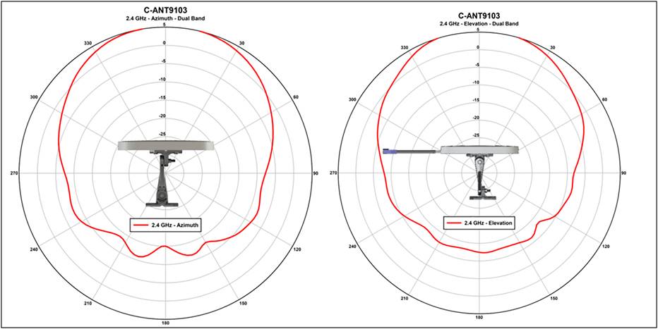
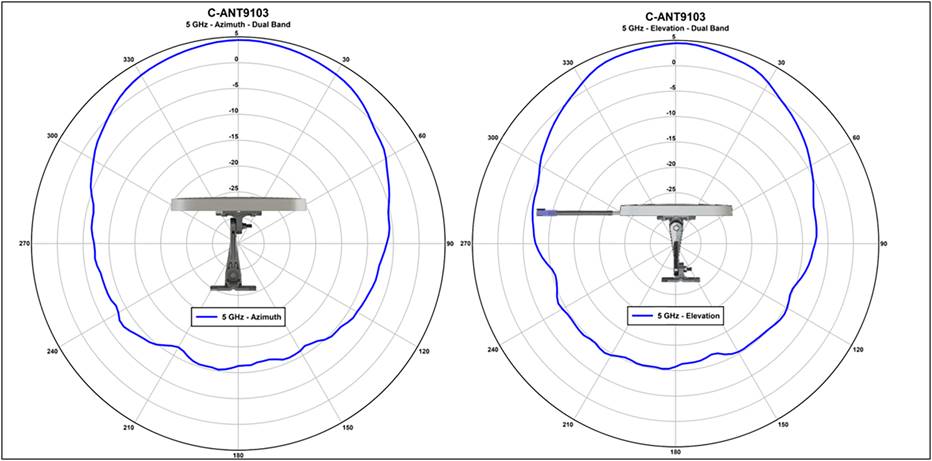
Beamwidth plots for the C-ANT9103 antenna
If the antenna cannot hear, it may not interfere with your AP. We have only three channels in 2.4 GHz; channel reuse in a dense deployment is already a problem there. With a good antenna, you can make the cell size smaller and get more radios closer together to provide adequate capacity in your design for 2.4-GHz users. 5 GHz has more channels; however, with 20-, 40-, and 80-MHz channel widths, we are using channels up faster, and cell isolation is becoming more of a problem.
Other problems that can be solved using directional antennas include high-interference environments – a shopping mall, for instance. Most of the stores in a shopping mall will have installed Wi-Fi, and this creates interference for your Wi-Fi. Using directional antennas, you can isolate your store from the neighbor by focusing the ears of the AP inward and making the receive sensitivity less behind the antenna. The front-to-back ratio of an antenna is responsible for this. Think of it as being like cupping your hands over your ears to hear a distant sound. When you do this, you focus the sound energy into your ears, but you also shield your ears to the surrounding noise, and this produces a better SNR – you experience it as better, more intelligible sound. Putting a directional antenna on your AP will similarly focus its ears, and it will experience better sound with less noise as well.
Newer antenna designs
● The external antenna connectors on the Catalyst APs are identical to the antenna connectors on previous APs. There is no difference in operation when the access point is used in dual-band (2.4 and 5 GHz) operation (the default mode). RF coverage and cell sizes are like those of the previous Aironet 2800 and 3800 Series.
● Like the prior external antenna versions, the new Catalyst 9120 Series access points now support the capability of dual 5-GHz operation. The main serving radios default to the following configuration:
◦ Dedicated 5-GHz radio is tied to the dual-band client-serving antennas at 4 dBi.
◦ (Exclusive OR) known as XOR radio (defaulted to 2.4 GHz) is tied to the dual-band client-serving antennas at 3 dBi.
◦ Dual 5-GHz mode: XOR 2.4-GHz disabled secondary 5-GHz radio is tied to the dedicated 5-GHz antennas at 4 dBi.
● Similarly, in the Catalyst 9120AXE access point, which has external antenna ports, for dual 5 GHz, a smart antenna connector must be used on the external antennas, as the additional 5-GHz radio cannot use the same top antennas on the access point that are being used by the primary 5-GHz radio.
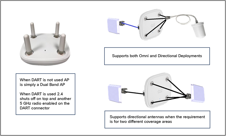
9120e antenna system using the DART connector for dual 5 GHz
● When a smart antenna connector is installed, the XOR radio (the radio that is defined in software as Radio 0) has its RF switched to the smart antenna connector.
● The smart antenna connector can detect the type of antenna used and has 16 digital lines as well as 4 analog RF lines.
● The self-identifying antenna ports are indicated by a different color (PURPLE). Figure 6 shows the traditional antenna ports and the DART ports.
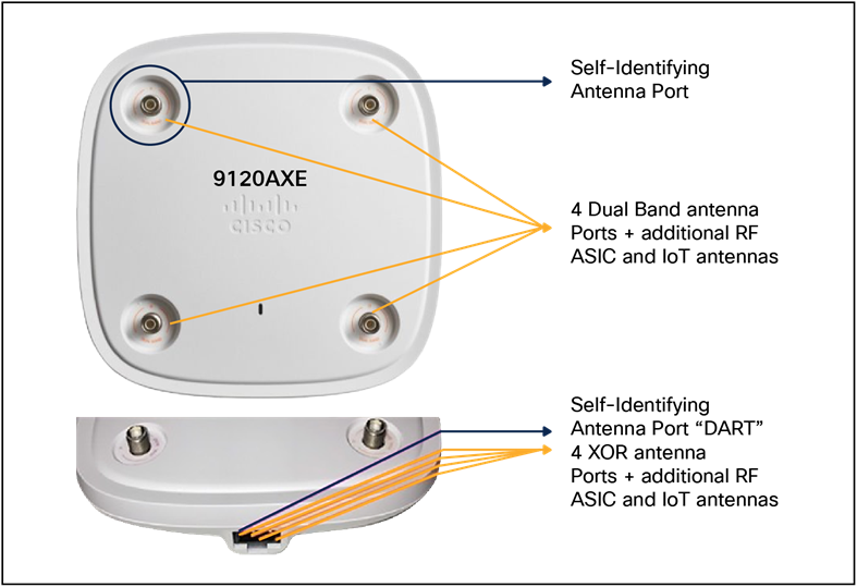
Catalyst 9120 antenna ports
When the smart antenna is not installed, the antenna on top of the unit is in Dual Radiating Element (DRE) mode. If the smart antenna connector is installed, the XOR (2.4 or 5 GHz, depending on the mode) goes out the smart connector. In this mode the XOR radio (unless in Monitor mode) can be configured for only one band, 2.4 GHz or the other band, 5 GHz. This is in Single Radiating Element (SRE) mode.
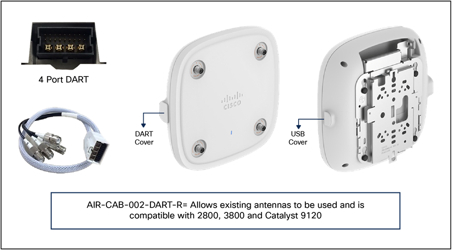
Cables to use with existing RP-TNC
Unlike the Catalyst 9120AXE, the Catalyst 9130AXE does not have antenna ports. The 9130AXE requires the use of an external antenna system. The yellow cover (on the left) must be removed and a suitable antenna system installed via the 8-port DART smart connector, which is exposed once the yellow cover is removed. Do not operate the unit without a suitable antenna.
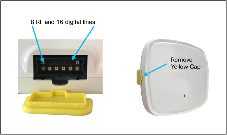
C9130AXE antenna connector
Three new antennas have been designed to support the Cisco Catalyst C9130AXE:
● C-ANT9101: Ceiling mount omni, like AIR-ANT2524V4C-R=.
● C-ANT9102: Wall/pole mount omni, like AIR-ANT2544V4M-R=.
● C-ANT9103: Wall/pole mount patch, like AIR-ANT2566D4M-R=.
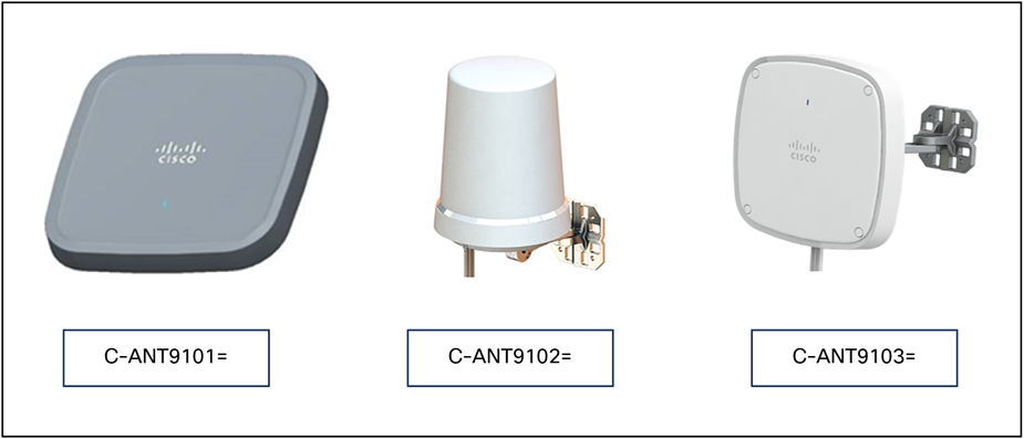
Antenna options
In addition to new antennas being designed with the smart connector, conventional antennas using RP-TNC connectors may attach to the Catalyst 9120or 9130 Series using the smart connector.
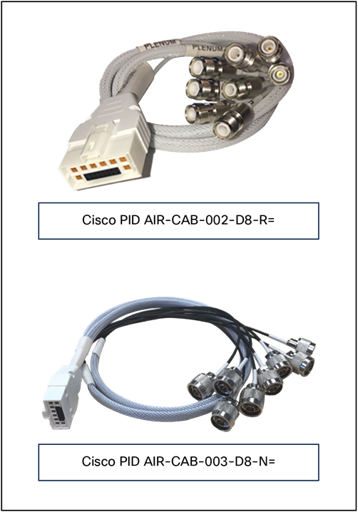
Smart connector
For more on this topic, see the Cisco Catalyst 9130 Series Access Point Deployment Guide at: https://www.cisco.com/c/en/us/products/collateral/wireless/catalyst-9100ax-access-points/deployment-guide-c07-743490.html.
Some design considerations can be addressed by general best practice guidelines. The following applies to most situations:
The number of users per AP that we recommend is as follows:
● 30 to 50 for data-only users.
● 10 to 20 for voice users.
This number should be used as a guideline and can vary depending on the AP model, handset, or application in use. Check your handset/application requirements.
● The AP data rates should be limited to those designed and for which the site survey was performed. Enabling lower data rates can cause increases in co-channel interference and greater throughput variations for clients. A common minimum data rate to start with is 12 Mbps.
● The number of APs depends on coverage and throughput requirements, which can vary. For example, the Cisco internal Information Systems group currently uses one AP per 3000 square feet of floor space.
Radio Resource Management (RRM)
The RRM software that is embedded in the device acts as a built-in RF engineer to consistently provide real-time RF management of your wireless network. RRM enables devices to continually monitor their associated lightweight access points for the following information:
Traffic load: The total bandwidth used for transmitting and receiving traffic. It enables wireless LAN managers to track and plan network growth ahead of client demand.
● Interference: The amount of traffic coming from other 802.11 sources.
● Noise: The amount of non-802.11 traffic that is interfering with the currently assigned channel.
● Coverage: The RSSI and SNR for all connected clients.
● Other: The number of nearby access points.
RRM performs these functions:
● Radio resource monitoring
● Power control transmission
● Dynamic Channel Assignment (DCA)
● Coverage hole detection and correction
● RF grouping
Note: RRM grouping does not occur when an AP operates in a static channel that is not in the DCA channel list. The Neighbor Discovery Protocol (NDP) is sent only on DCA channels; therefore, when a radio operates on a non-DCA channel, it does not receive NDP on the channel.
RRM automatically detects and configures new devices and lightweight access points as they are added to the network. It then automatically adjusts the associated and nearby lightweight access points to optimize coverage and capacity.
Lightweight access points can scan all the valid channels for the country of operation as well as for channels available in other locations. The access points in local mode go off channel for a period not greater than 0 ms to monitor these channels for noise and interference. Packets collected during this time are analyzed to detect rogue access points, rogue clients, ad hoc clients, and interfering access points.
Note: In the presence of voice traffic or other critical traffic (in the last 100 ms), access points can defer off-channel measurements. The access points also defer off-channel measurements based on the WLAN scan priority configurations.
Each access point spends only 0.2 percent of its time off channel. This activity is distributed across all the access points so that adjacent access points are not scanning at the same time, which could adversely affect WLAN performance.
An RF group is a logical collection of controllers that coordinate to conduct RRM in a globally optimized manner to perform network calculations on a per-radio basis. Separate RF groups exist for 2.4-GHz and 5-GHz networks. Clustering Catalyst 9800 Series controllers into a single RF group enables the RRM algorithms to scale beyond the capabilities of a single controller.
An RF group is created based on the following parameters:
● User-configured RF network name.
● Neighbor discovery performed at the radio level.
● Country list configured on the controller.
RF grouping runs between controllers.
Lightweight access points periodically send out neighbor messages over the air. Access points using the same RF group name validate messages from each other.
When access points on different controllers hear validated neighbor messages at a signal strength of 80 dBm or stronger, the controllers dynamically form an RF neighborhood in auto mode. In static mode, the leader is manually selected, and the members are added to the RF group.
Note: RF groups and mobility groups are similar in that they both define clusters of controllers, but they are different in terms of their use. An RF group facilitates scalable, systemwide, dynamic RF management, while a mobility group facilitates scalable, systemwide mobility and controller redundancy.
RF group leader
An RF group leader can be configured in one of two ways, as follows:
Note: The RF group leader is chosen based on the controller with the greatest AP capacity (platform limit.) If multiple controllers have the same capacity, the leader is the one with the highest management IP address.
● Auto mode: In this mode, the members of an RF group elect an RF group leader to maintain a primary power and channel scheme for the group. The RF grouping algorithm dynamically chooses the RF group leader and ensures that an RF group leader is always present. Group leader assignments can and do change (for instance, if the current RF group leader becomes inoperable or RF group members experience major changes).
● Static mode: In this mode, a user selects a controller as an RF group leader manually. The leader and the members are manually configured and fixed. If the members are unable to join the RF group, the reason is indicated. The leader tries to establish a connection with a member every minute if the member has not joined in the previous attempt.
The RF group leader analyzes real-time radio data collected by the system, calculates the power and channel assignments, and sends them to each of the controllers in the RF group. The RRM algorithms ensure systemwide stability and restrain channel and power scheme changes to the appropriate local RF neighborhoods.
Note: When a controller becomes both leader and member for a specific radio, you get to view the IPv4 and IPv6 address as part of the group leader.
When Controller A becomes a member and Controller B becomes a leader, Controller A displays either the IPv4 or IPv6 address of Controller B using the address it is connected with.
So if both leader and member are not the same, you get to view only one IPv4 or IPv6 address as a group leader in the member.
If DCA needs to use the worst-performing radio as the single criterion for adopting a new channel plan, it can result in pinning or cascading problems.
The main cause of both pinning and cascading is that any potential channel plan changes are controlled by the RF circumstances of the worst-performing radio. The DCA algorithm does not do this; instead, it does the following:
● Multiple local searches: The DCA search algorithm performs multiple local searches initiated by different radios in the same DCA run rather than performing a single global search that is driven by a single radio. This change addresses both pinning and cascading while maintaining the desired flexibility and adaptability of DCA and without jeopardizing stability.
● Multiple Channel Plan Change Initiators (CPCIs): Previously, the single worst radio was the sole initiator of a channel plan change. Now each radio in an RF group is evaluated and prioritized as a potential initiator. Intelligent randomization of the resulting list ensures that every radio is eventually evaluated, which eliminates the potential for pinning.
● Limiting the propagation of channel plan changes (localization): For each CPCI radio, the DCA algorithm performs a local search for a better channel plan, but only the CPCI radio itself and its one-hop neighboring access points are allowed to change their current transmit channels. The impact of an access point triggering a channel plan change is felt only to within two RF hops from that access point, and the actual channel plan changes are confined to within a one-hop RF neighborhood. Because this limitation applies across all CPCI radios, cascading cannot occur.
● Non-RSSI-based cumulative cost metric: A cumulative cost metric measures how well an entire region, neighborhood, or network performs with respect to a given channel plan. The individual cost metrics of all the access points in that area are considered to provide an overall understanding of the channel plan’s quality. These metrics ensure that the improvement or deterioration of each single radio is factored into any channel plan change. The objective is to prevent channel plan changes in which a single radio improves, but at the expense of multiple other radios experiencing a considerable performance decline.
The RRM algorithms run at a specified update interval, which is 600 seconds by default. Between update intervals, the RF group leader sends keep-alive messages to each of the RF group members and collects real-time RF data.
For more information on RRM, see the Catalyst 9800 Radio Resource Management Deployment Guide at https://www.cisco.com/c/en/us/td/docs/wireless/controller/technotes/8-8/b_C9800_rrm_dg.html.
RF group name
A controller is configured in an RF group name, which is sent to all the access points joined to the controller and used by the access points as the shared secret for generating the hashed MIC in the neighbor messages. To create an RF group, you configure all the controllers to be included in the group with the same RF group name.
If there is any possibility that an access point joined to a controller might hear RF transmissions from an access point on a different controller, you should configure the controller with the same RF group name. If RF transmissions between access points can be heard, systemwide RRM is recommended to avoid 802.11 interference and contention as much as possible.
Secure RF groups
Secure RF groups enable to encrypt and secure RF grouping and RRM message exchanges over a DTLS tunnel. During the DTLS handshake, controllers authenticate each other with a wireless management trust-point certificate.
The device dynamically controls access point transmit power based on the real-time wireless LAN conditions.
The TPC algorithm increases and decreases an access point’s power in response to changes in the RF environment. In most instances, TPC seeks to lower an access point's power to reduce interference, but in the case of a sudden change in the RF coverage – for example, if an access point fails or becomes disabled – TPC can also increase power on the surrounding access points. This feature is different from coverage hole detection, which is primarily concerned with clients. TPC provides enough RF power to achieve the required coverage levels while avoiding channel interference between access points. We recommend that you select TPCv1; the TPCv2 option is deprecated. With TPCv1, you can select the channel-aware mode; we recommend that you select this option for 5 GHz and leave it unchecked for 2.4 GHz.
Overriding the TPC algorithm with minimum and maximum transmit power settings
The TPC algorithm balances RF power in many diverse RF environments. However, it is possible that automatic power control will not be able to resolve some scenarios in which implementing an adequate RF design was not possible due to architectural restrictions or site restrictions – for example, when all the access points must be mounted in a central hallway, requiring them to be placed close together, but coverage is required to the edge of the building.
In these scenarios, you can configure maximum and minimum transmit power limits to override TPC recommendations. The maximum and minimum TPC power settings apply to all the access points through RF profiles in a RF network.
To set the maximum power level assignment and minimum power level assignment, enter the maximum and minimum transmit power used by RRM in the fields in the Tx Power Control window. The range for these parameters is 10 to 30 dBm. The minimum value cannot be greater than the maximum value; the maximum value cannot be less than the minimum value.
If you configure a maximum transmit power, RRM does not allow any access point attached to the controller to exceed this transmit power level (whether the power is set by RRM TPC or by coverage hole detection). For example, if you configure a maximum transmit power of 11 dBm, no access point will transmit above 11 dBm, unless the access point is configured manually.
Cisco APs support power level changes in 3-dB granularity. TPC Min and Max power settings allow for values in 1-dB increments. The resulting power level will be rounded to the nearest value supported in the allowed power entry for the AP model and the current serving channel.
Each AP model has its own set of power levels localized for its regulatory country and region. Moreover, the power levels for the same AP model will vary based on the band and channel it is set to. For more information on allowed power level vs. actual power (in dBm), use the show ap name <name> config slot <0|1|2|3> command to view the specific number of power levels, the range of power levels allowed, and the current power level setting on the AP.
Dynamic Channel Assignment (DCA)
Two adjacent access points on the same channel can cause either signal contention or signal collision. In a collision, data is not received by the access point. This functionality can become a problem when, for example, someone reading an email in a café affects the performance of the access point in a neighboring business. Even though these are separate networks, someone sending traffic to the café on channel 1 can disrupt communication in an enterprise using the same channel. Devices can dynamically allocate access point channel assignments to avoid conflict and increase capacity and performance. Channels are reused to avoid wasting scarce RF resources. In other words, channel 1 is allocated to a different access point far from the café, which is more effective than not using channel 1 altogether.
The device’s DCA capabilities are also useful in minimizing adjacent channel interference between access points. For example, two overlapping channels in the 802.11b/g band, such as 1 and 2, cannot simultaneously use 11 or 54 Mbps. By effectively reassigning channels, the device keeps adjacent channels that are separated.
The device examines a variety of real-time RF characteristics to efficiently handle channel assignments as follows:
● Access point received energy: The RSSI measured between each access point and its nearby neighboring access points. Channels are optimized for the highest network capacity.
● Noise: Noise can limit signal quality at the client and access point. An increase in noise reduces the effective cell size and degrades user experience. By optimizing channels to avoid noise sources, the device can optimize coverage while maintaining system capacity. If a channel is unusable due to excessive noise, that channel can be avoided.
● 802.11 interference: Interference is any 802.11 traffic that is not a part of your WLAN, including rogue access points and neighboring wireless networks. Lightweight access points constantly scan all the channels looking for sources of interference. If the amount of 802.11 interference exceeds a predefined configurable threshold (the default is 10 percent), the access point sends an alert to the device. Using the RRM algorithms, the device may then dynamically rearrange channel assignments to increase system performance in the presence of the interference. Such an adjustment could result in adjacent lightweight access points being on the same channel, but this setup is preferable to having the access points remain on a channel that is unusable due to an interfering foreign access point.
● In addition, if other wireless networks are present, the device shifts the usage of channels to complement the other networks. For example, if one network is on channel 6, an adjacent WLAN is assigned to channel 1 or 11. This arrangement increases the capacity of the network by limiting the sharing of frequencies. If a channel has virtually no capacity remaining, the device may choose to avoid this channel. In huge deployments in which all nonoverlapping channels are occupied, the device does its best, but you must consider RF density when setting expectations.
● Load and utilization: When utilization monitoring is enabled, capacity calculations can consider that some access points are deployed in ways that cause them to carry more traffic than other access points, for example, a lobby versus an engineering area. The device can then assign channels to improve the access point that has performed the worst. The load is considered when changing the channel structure to minimize the impact on the clients that are currently in the WLAN. This metric keeps track of every access point’s transmitted and received packet counts to determine how busy the access points are. New clients avoid an overloaded access point and associate to a new access point. This load and utilization parameter is disabled by default.
The device combines this RF characteristic information with RRM algorithms to make systemwide decisions. Conflicting demands are resolved using soft-decision metrics that guarantee the best choice for minimizing network interference. The result is optimal channel configuration in a three-dimensional space, where access points on the floors above and below play a major factor in an overall WLAN configuration.
Note: DCA supports only 20-MHz channels in 2.4-GHz band.
Note: In a Dynamic Frequency Selection (DFS)-enabled AP environment, ensure that you enable the UNII2 channels option under the DCA channel to allow 100-MHz separation for the dual 5-GHz radios.
The RRM start-up mode is invoked under the following conditions:
● In a single-device environment, the RRM start-up mode is invoked after the device is upgraded and rebooted.
● In a multiple-device environment, the RRM start-up mode is invoked after an RF group leader is elected.
● You can trigger the RRM start-up mode from the Command-Line Interface (CLI).
The RRM start-up mode runs for 100 minutes (10 iterations at 10-minute intervals). The duration of the RRM start-up mode is independent of the DCA interval, sensitivity, and network size. The start-up mode consists of 10 DCA runs with high sensitivity (making channel changes easy and sensitive to the environment) to converge to a steady-state channel plan. After the start-up mode is finished, DCA continues to run at the specified interval and sensitivity.
Note: The DCA algorithm interval is set to 1 hour, but the algorithm always runs in default intervals of 10 minutes, channel allocation occurs at 10-minute intervals for the first 10 cycles, and channel changes occur as per the DCA algorithm every 10 minutes. After that, the DCA algorithm goes back to the configured time interval. This is common for both DCA interval and anchor time because it follows the steady state.
Note: If DCA/TPC is turned off on the RF group member, and auto is set on RF group leader, the channel or TX power on a member gets changed as per the algorithm that is run on the RF group leader.
Dynamic Bandwidth Selection (DBS)
While upgrading from 11n to 11ac, the DBS algorithm provides a smooth transition for various configurations.
The following describes the functionalities of DBS:
● It applies an additional layer of bias on top of those applied to the core DCA, for channel assignment to maximize the network throughput by dynamically varying the channel width.
● It fine-tunes the channel allocations by constantly monitoring the channel and base station subsystem statistics.
● It evaluates the transient parameters, such as 11n or 11ac client mix, load, and traffic flow types.
● It reacts to the fast-changing statistics by varying the BSS channel width or adapting to the unique and new channel orientations through 11ac for selection between 40-MHz and 80-MHz bandwidths.
Coverage hole detection and correction
The RRM coverage hole detection algorithm can detect areas of radio coverage in a WLAN that are below the level needed for robust radio performance. This feature can alert you to the need for an additional (or relocated) lightweight access point.
If clients on a lightweight access point are detected at threshold levels (RSSI, failed client count, percentage of failed packets, or number of failed packets) lower than those specified in the RRM configuration, the access point sends a “coverage hole” alert to the device. The alert indicates the existence of an area where clients are continually experiencing poor signal coverage without having a viable access point to which to roam. The device discriminates between coverage holes that can and cannot be corrected. For coverage holes that can be corrected, the device mitigates the coverage hole by increasing the transmit power level for that specific access point. The device does not mitigate coverage holes caused by clients that are unable to increase their transmit power or are statically set to a power level because increasing their downstream transmit power might increase interference in the network.
AI-Enhanced RRM is the next evolution of Cisco's award-winning RRM.
RRM runs as a service in a Catalyst 9800 Series wireless controller. It RRM manages the RF group based on dynamic measurements between every AP and its neighbor stored in a local database for the entire RF group. At runtime, the RRM draws the last 10 minutes of collected data and gently optimizes based on the current network conditions.
AI-Enhanced RRM integrates the power of artificial intelligence and machine learning into the reliable and trusted Cisco RRM product family algorithms in the cloud.
Note: AI-Enhanced RRM is coordinated through Cisco DNA Center (on-premises appliance) as a service. The current RRM sites are seamlessly transitioned to an intelligent centralized service. AI-Enhanced RRM, along with other Cisco DNA Center services, brings a host of new features with it.
Cisco AI-Enhanced RRM operates as a distributed RRM service. The controller collects RF telemetry from the Cisco access points and passes it through Cisco DNA Center to the Cisco AI Analytics Cloud, where the data is stored. The RRM algorithms run against this telemetry data stored in the cloud. AI analyzes the solutions and passes any configuration change information back to Cisco DNA Center. Cisco DNA Center maintains the control connection with the enrolled controller and passes any individual AP configuration changes back to the APs.
The following RRM algorithms run in the cloud, while the remaining ones work in the controller:
● DCA
● TPC
● DBS
● FRA
Note: The RRM algorithms run in the cloud against the telemetry data available in the cloud.
If the locations of controller and APs are provisioned previously, assigning a location enrolls the AI-Enhanced RRM Services and the profile to be pushed to the controller. Thus, AI-Enhanced RRM becomes the RF group leader for the subscribed controller.
For more information about Cisco DNA Center, see Cisco DNA Center User Guide. https://www-author4.cisco.com/c/en/us/support/cloud-systems-management/dna-center/products-user-guide-list.html.
Spontaneous interference is interference that appears suddenly on a network, perhaps jamming a channel or a range of channels completely. The Cisco CleanAir® spectrum event-driven RRM feature allows you to set a threshold for air quality that, if exceeded, triggers an immediate channel change for the affected access point. Once a channel change occurs due to event-driven RRM, the channel is blocked for three hours to avoid selection. Most RF management systems can avoid interference, but this information takes time to propagate through the system. Cisco CleanAir relies on air quality measurements to continuously evaluate the spectrum and can trigger a move within 30 seconds. For example, if an access point detects interference from a video camera, it can recover by changing channels within 30 seconds of the camera becoming active.
Flexible Radio Assignment (FRA)
FRA takes advantage of the dual-band radios included in APs. It is a new feature added to RRM to analyze the Neighbor Discovery Protocol (NDP) measurements, which manages the hardware used to determine the role of the new flexible radio (2.4 GHz, 5 GHz, or monitor) in your network.
Traditional legacy dual-band APs always had two radio slots, (one slot per band) and were organized by the band they were serving, that is, slot 0 = 802.11b, g, n, and slot 1 = 802.11a, n, ac.
XOR support in 2.4-GHz or 5-GHz bands
The flexible radio (XOR) offers the ability to serve the 2.4-GHz or the 5-GHz bands or to passively monitor both bands on the same AP. The AP models that are offered are designed to support dual 5-GHz band operations, with the Cisco APs’ “I” models (such as the Catalyst 9120AXI) supporting a dedicated macro/micro architecture and the “E” and “P” models supporting a macro/macro architecture.
When using FRA with the internal antenna (“I” models), two 5-GHz radios can be used in a micro/macro cell mode. When using FRA with external antenna (“E” and “P” models), the antennas may be placed to enable the creation of two separate macro cells (wide-area cells) or two micro cells (small cells) for High Density Experience (HDX) or any combination.
FRA calculates and maintains a measurement of redundancy for 2.4-GHz radios and represents this as a new measurement metric called Coverage Overlap Factor (COF).
This feature is integrated into existing RRM and runs in mixed environments with legacy APs. The AP MODE selection sets the entire AP (slots 0 and 1) into one of several operating modes, including:
● Local mode
● Monitor mode
● FlexConnect mode
● Sniffer mode
● Spectrum Connect mode
Before XOR was introduced, changing the mode of an AP propagated the change to the entire AP, that is, both radio slot 0 and slot 1. The addition of the XOR radio in the slot 0 position provides the ability to operate a single radio interface in many of the previous modes, eliminating the need to place the whole AP into a mode. When this concept is applied to a single radio level, it is called a role. Three such roles can be assigned now:
● Client serving
● Either 2.4 GHz (1) or 5 GHz (2)
● Monitor-Monitor mode (3)
Note: A mode is assigned to a whole AP (slot 0 and slot 1).
Note: A role is assigned to a single radio interface (slot 0).
FRA functions
FRA performs several functions. On the 2.4-GHz and 5-GHz XOR models, FRA establishes the required 2.4-GHz coverage, identifies redundant radios, and converts them to either 5 GHz or a monitor role. For tri-radio and 5/6-GHz XOR models, FRA determines the 2.4-GHz coverage, and the redundant radios are converted to a monitor role. Additionally, FRA determines the best operating role for the 5-GHz tri-radio (as either a single 8x8 or a dual 4x4), based on connected client capabilities. For the 5/6-GHz XOR radio, the band that the radios should operate on is based on the availability of 6-GHz in the regulatory domain.
FRA also manages the resulting configurations of the radios to optimize client experience across flexible roles. Client steering is responsible for load-balancing client connections. For instance, from Cisco Aironet 2800 Aps through Cisco Catalyst 9120 Series Aps, all the internal antenna AP models perform dual 5-GHz roles as a macro/micro cell (a cell within a cell). The antennas on these models are built to support the directionality needed for the micro cell. FRA client steering helps to steer clients to the appropriate radio based on their position within the cell (closer clients are put on the micro cell).
The internal antenna tri-radio models operate as micro/meso, with the variable power balancing the frequency and power of dual 5 GHz to create two overlapping cells. Client steering and load balancing also drive clients to balance the two cells and optimize capacity. The FRA Aps that support external antennas operate as macro/macro, which allows full control over power and channels. The Catalyst 9166I AP also supports a macro/macro model when using the internal antennas.
In Catalyst 9130 and 9136 Aps, FRA also manages the operating mode of the band-locked 8x8 5-GHz tri-radio by monitoring client capabilities of connected clients. For instance, if the attached clients are largely Wi-Fi 5-capable clients, then beamforming should be multiuser multiple input, multiple output (MU-MIMO), ensuring better capacity with dual 4x4 5-GHz cells. However, if the same cell has a higher number of Wi-Fi 6-capable clients, then 8x8 spatial streams support more MU-MIMO capacity and increase the overall performance of the cell and client experience.
The Catalyst 9166 Series are the first Aps with a dual-band XOR radio covering the 5-GHz and 6-GHz bands. The criterion for role selection is the regulatory domain (that is, whether the country’s regulatory rules support 6-GHz operations). If yes, 6 GHz is chosen. If not, 5-GHz operations are chosen.
Configuration choices for all FRA radio models include the following:
● Automatic (allows FRA to manage role selection automatically).
● Client serving (manual role selection of 2.4 GHz, 5 GHz, or 6 GHz, or FRA is not engaged).
● Monitor (manual: no FRA).
● Sniffer (manual: no FRA).
Benefits of FRA
● Solves the problem of 2.4-GHz over coverage.
● Creating two diverse 5-GHz cells doubles the airtime that is available.
● Permits one AP with one Ethernet drop to function like two 5-GHz Aps.
● Introduces the concept of macro/micro cells for airtime efficiency.
● Allows more bandwidth to be applied to an area within a larger coverage cell.
● Can be used to address nonlinear traffic.
● Enhances HDX with one AP.
● XOR radio can be selected by the corresponding user in either band, servicing Client mode or Monitor mode.
The dual-band (XOR) radio in the Aironet 2800, 3800, and 4800 Series and in the Catalyst 9120 Series AP models offers the ability to serve 2.4-GHz or 5-GHz bands or to passively monitor both of the bands on the same AP. These APs can be configured to serve clients in the 2.4-GHz and 5-GHz bands or to serially scan both the 2.4-GHz and 5-GHz bands on the flexible radio while the main 5-GHz radio serves clients.
Cisco AP models up and through the Catalyst 9120 Series are designed to support dual 5-GHz band operations, with the “I” model supporting a dedicated macro/micro architecture and the “E” and “P” models supporting macro/macro. The Catalyst 9130AXI and 9136 APs support dual 5-GHz operations as a micro/meso cell.
When a radio moves between bands (from 2.4 GHz to 5 GHz and vice versa), clients need to be steered to get an optimal distribution across radios. When an AP has two radios in the 5-GHz band, client steering algorithms contained in the FRA algorithm are used to steer a client between co-resident radios in the same band.
The XOR radio support can be steered manually or automatically:
Manual steering of a band on a radio: The band on the XOR radio can only be changed manually.
Automatic client and band steering on the radios is managed by the FRA feature that monitors and changes the band configurations as per site requirements.
Note: RF measurement will not run when a static channel is configured on slot 1. Due to this, the dual-band radio slot 0 will move only with the 5-GHz radio and not to the Monitor mode.
When the slot 1 radio is disabled, RF measurement will not run, and the dual-band radio slot 0 will be only on the 2.4-GHz radio.
Receiver Start of Packet Detection Threshold
The Receiver Start of Packet (Rx SOP) Detection Threshold feature determines the Wi-Fi signal level in dBm at which an access point's radio demodulates and decodes a packet. As the Wi-Fi level increases, the radio sensitivity decreases and the receiver cell size becomes smaller. Reduction of the cell size affects the distribution of clients in the network.
Rx SOP is used to address clients with weak RF links, sticky clients, and client load balancing across access points. Rx SOP helps to optimize network performance in high-density deployments, such as stadiums and auditoriums, where access points need to optimize the nearest and strongest clients.
Restrictions for Rx SOP
Rx SOP configuration is not applicable to the third radio module pluggable on Aironet 3600 Series APs.
Rx SOP configurations are supported only in Local, FlexConnect, Bridge, and Flex+Bridge modes.
Rx SOP configurations are not supported in the FlexConnect+PPPoE, FlexConnect+PPPoE-WIPS, and FlexConnect+OEAP submodes.
The following table shows the permitted range for the Rx SOP threshold.
Table 4. Rx SOP threshold
| Radio Band |
Threshold High |
Threshold Medium |
Threshold Low |
| 2.4 GHz |
-79 dBm |
-82 dBm |
-85 dBm |
| 5 GHz |
-76 dBm |
-78 dBm |
-80 dBm |
This feature enforces a limit on the number of clients that can be associated with an AP. Further, you can configure the number of clients that can be associated with each AP radio.
The IP theft feature prevents the use of an IP address that is already assigned to another device. If the controller finds that two wireless clients are using the same IP address, it declares the client with lesser precedence binding as the IP thief and allows the other client to continue. If a blocked list is enabled, the client is put on the exclusion list and thrown out.
The IP theft feature is enabled by default on the controller. The preference level of the clients (new and existing clients in the database) is also used to report IP theft. The preference level is a learning type or source of learning, such as DHCP, ARP, data glean (looking at the IP data packet that shows what IP address the client is using), and so on. Wired clients always get a higher preference level. If a wireless client tries to steal the wired IP, that client is declared as a thief.
The order of preference for IPv4 clients is:
● DHCPv4
● ARP
● Data packets
The order of preference for IPv6 clients is:
● DHCPv6
● NDP
● Data packets
Dynamic Frequency Selection (DFS)
DFS is the process of detecting radar signals and automatically setting the frequency on a DFS-enabled 5.0-GHz (802.11a/h) radio to avoid interference with the radar signals. Radios configured for use in a regulatory domain must not interfere with radar systems.
In normal DFS, when a radar signal is detected on any of the channels in the 40-MHz or 80-MHz bandwidth, the whole channel is blocked. With Flex DFS, if the radar signals are not detected on the secondary channel, the AP is moved to a secondary channel with a reduction in the bandwidth, usually by half.
Optimized Roaming is a tool that can help resolve the problem of sticky clients that remain stubbornly associated to an access point instead of roaming to a more robust available connection. The client alone makes the decision as to when and to whom to roam, and not all clients are created equal. The Optimized Roaming feature borrows some of the same rich data gathered from the APs as the coverage hole algorithm detailed earlier in this chapter. Optimized roaming looks at the data RSSI of the client as measured by the AP against the Data RSSI threshold set in the Coverage Hole configuration dialog. If a client falls below this threshold, the client is sent a disassociation message (Reason 4 – Timeout). The default configuration sets Optimized Roaming as disabled and uses the Data RSSI in the Coverage Hole dialog for coverage hole calculations. Optimized Roaming also has an optional metric – data rate – that is disabled by default and can be used to form a double gate based on the RSSI threshold AND the data rate of the received data packets. If the data rate is also used, both must be true to trigger a disassociation event.
Optimized Roaming, once triggered for a given client, also prevents client reassociation when the client's RSSI is below the threshold and requires the client to be 6 dB above the disassociation threshold to reassociate to that AP. It is for this reason alone that it is not advised to also use the less-known RSSI low check feature. The two thresholds DO NOT work in conjunction with each another, and you can inadvertently lock out a cell’s access.
From Cisco IOS XE Cupertino 17.7.1 onward, the Catalyst 9136I access point supports the 6-GHz band. The 6-GHz band provides more channels and more bandwidth and has less network congestion when compared to the existing 2.4-GHz and 5-GHz bands. As a result, wireless clients that are 6-GHz capable connect to the 6-GHz radio to take advantage of these benefits.
6-GHz client steering takes place when the controller receives a periodic client statistics report from the 2.4-GHz band or the 5-GHz band. The client steering configuration is enabled under the WLAN and is configured only for clients that are 6-GHz capable. If a client in the report is 6-GHz capable, client steering is triggered and the client is steered to the 6-GHz band.
● The U-NII-2 and U-NII-2C(e) bands, also known as the DFS channels (Dynamic Frequency Assignment), require a 60-second (or more) channel availability check (CAC) before being used by Wi-Fi to ensure that no radar is in operation.
● Zero Wait DFS allows the use of the AP resources to perform a preemptive CAC before a channel change is initiated, eliminating the 60- to 600-second delay experienced on a channel change to any DFS channel.
Prior to Release 17.8 of Cisco IOS XE, DFS CAC has been performed on demand as a precursor to assuming Wi-Fi operations on a channel. This behavior is required to verify that there is no radar operating on the channel we will assume. Part of this also requires that we continue to scan during channel operation, and we immediately abandon the channel if radar is detected. When RRM assigns a channel, it assigns the “best” channel available in the current DCA run. A second-best channel is also assigned at the time which is labeled as a future channel. In the event of a radar detection on the current DFS channel, the future channel would be scanned quickly and then used. This mini DCA has already ensured that the succession channel is a good choice based on the channel adjacencies. If that future channel happens to be a DFS-required channel, the AP would scan for 60 seconds (or 600 seconds if ETSI Terminal Doppler Weather Radar [TDWR] channels 120, 124, or 128) and then assume beaconing again on the new channel.
The Zero Wait DFS feature is supported for ETSI and FCC in the Catalyst 9130 Series APs only beginning with Cisco IOS XE Release 17.9, and support for the Catalyst 9136 Series APs is available starting from Cisco IOS XE Release 17.11.1.
The Catalyst 9130 Series APs can run 5 GHz in 8x8 or dual 5-GHz 4x4 mode.
The default mode on the 9130 Series is 5-GHz 8x8 and 2.4-GHz 4x4 mode. This default mode provides the highest throughput per single radio, with performance gains mainly in MU-MIMO client environments. This mode provides a better data rate but less range, with more receivers hearing the client for better Maximal-Ratio Combining (MRC).
There are instances when it becomes beneficial to change the operation of the 5-GHz radio from 8x8 into two independent 5-GHz 4x4 radios. The benefit with dual 5-GHz 4x4 radios is that it allows for macro-micro cell operation, which is very useful in high-density environments. It also permits more clients for greater performance when there are fewer Wi-Fi 6-capable clients or when the need arises to create two different 5-GHz Wi-Fi coverage cells or change operational modes such as monitoring.
Table 5. Catalyst 9130 radio roles
| 5GHz Radio Role |
Drivers |
|
| Radio 1 |
Radio 2 |
|
| 8x8 Client serving |
None |
Preferred operation in 160 MHz or 80+80MHz Higher MU-MIMO stations Lower Channel reuse requirement Required Higher Number of Spatial Stream (SS) |
| 4x4 Client serving |
4x4 Client serving |
High Client Density and Capacity requirements Directional Antenna Units (Coverage slicing) Operation as 80MHz or below |
| 4x4 Client serving |
Monitor |
Lower MU-MIMO stations Low density, better channel reuse Monitoring Application Requires 4x4 Rx |
| 5GHz |
Criteria |
|
| Radio 1 |
Radio 2 |
|
| 8x8 Client serving |
None |
Preferred operation in 160 MHz or 80+80MHz Higher MU-MIMO stations Better channel re-use rate in high density Required Higher Number of Spatial Stream (SS) |
| 4x4 Client serving |
4x4 Client serving |
High legacy client capacity requirements Directional antenna units (Coverage Slicing) Operation as 80MHz or below |
| 4x4 Client serving |
Monitor |
Lower MU-MIMO stations Low density, better channel reuse Monitoring application requires 4x4 Rx |
The XOR radio in APs such as the Aironet 2800, 3800, and 4800 Series and the Catalyst 9100 APs support the sniffer role in the single-radio interface.
The XOR radio offers the ability to operate as a single-radio interface in many modes. This eliminates the need to place the entire AP into a mode. When this concept is applied to a single radio level, it is called a role.
Note: The radio role is supported in Local and Flex Connect modes.
The Cisco Unified Wireless Network solution provides end-to-end security of architecture and product security features to protect WLAN endpoints, the WLAN infrastructure, and client communications.
The solution builds upon the base security features of the IEEE 802.11-2012 standard by enhancing RF and network-based security features to help ensure overall security.
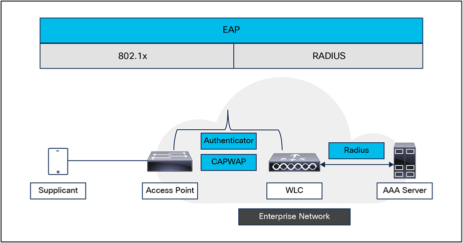
Secure wireless topology
Security is implemented using authentication and encryption in the WLAN network. The security mechanisms for WLAN networks are:
● Open authentication (no encryption).
● Wi-Fi Protected Access 2 (WPA2).
● Wi-Fi Protected Access 3 (WPA3).
● Opportunistic Wireless Encryption (OWE).
● Identity PSK (WPA2 PSK + MAC filtering) (iPSK).
● Multi-PSK (MPSK).
● Cisco Rogue Detection and Adaptive Wireless Intrusion Prevention System (aWIPS).
● Segmentation.
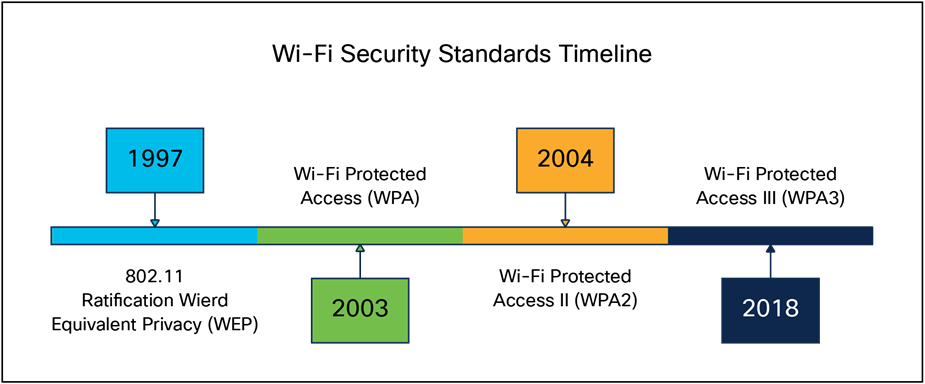
Wi-Fi security timeline
WPA2 is the second generation of Wi-Fi security based on the ratified IEEE 802.11i standard and is also approved by the Wi-Fi Alliance interoperability implementation of the 802.11i standard. WPA2 provides certification in both Enterprise and Personal classifications.
The Enterprise classification requires support for a RADIUS/802.1X-based authentication and pre-shared key; the Personal classification requires only a common key shared by the client and the AP.
The AES mechanism introduced in WPA2 generally requires a hardware upgrade of WLAN clients and APs; however, all Cisco CAPWAP hardware is WPA2 enabled.
WPA3 is the third and latest iteration of the Wi-Fi Protected Access standard developed by the Wi-Fi Alliance and replaces the previous standard, WPA2. The WPA standard was created by the Wi-Fi Alliance security technical task group, chaired by Cisco’s Stephen Orr, with the purpose of standardizing wireless security. WPA3 introduces new features on enterprise, personal, and open security networks through an increase in cryptographic strength, allowing for a more secure authentication process for all WPA3-supported endpoints.
Over the next few years, we expect the industry to see an exponential increase in WPA3 adoption, especially in government and financial institutions. With the number of internet-connected devices forecasted to reach 41.6 billion in four years, there is an implicit need for better security, and WPA3 is the answer.
Supported WPA3 modes
● WPA3-Enterprise, for 802.1X security networks. This leverages IEEE 802.1X with SHA-256 as the Authentication and Key Management (AKM).
● WPA3-Personal, which uses the Simultaneous Authentication of Equals (SAE) method for personal security networks.
● WPA3 Transition Mode (WPA2+WPA3 security-based WLANs for both personal and enterprise).
● Opportunistic Wireless Encryption (OWE) for open security networks.
● WPA3-Personal SAE hash-to-element method for password element generation (minimum software version 17.7.1).
● WPA3-Enterprise and WPA3-Personal Transition disabled (minimum software version 17.7.1).
● WPA3-Personal with SAE as AKM + Fast Transition (FT) (minimum software version 17.9.1).
OWE is a security method paired with an open-security wireless network to provide it with encryption to protect the network from eavesdroppers. With OWE, the client and AP perform a Diffie-Hellman key exchange during the endpoint association packet exchange and use the resulting PMK to conduct the four-way handshake. Being associated with open-security wireless networks, OWE can be used with regular open networks as well as those associated with captive portals.
Traditional Pre-Shared Key (PSK) secured networks use the same password for all the connected clients. This can result in the key being shared with unauthorized users, causing a security breach and unauthorized access to the network. The most common mitigation of this breach is to change the PSK itself, a change that impacts all users, since many end devices will need to be updated with the new key to access the network again.
With identity PSK (iPSK), unique pre-shared keys are created for individuals or a group of users on the same SSID with the help of a RADIUS server. This kind of setup is extremely useful in networks where end-client devices do not support 802.1X authentication, but a more secure and granular authentication scheme is needed. From a client perspective, this WLAN looks identical to the traditional PSK network. In the event that one of the PSKs is compromised, only the affected individual or group need to have their PSK updated. The rest of the devices connected to the WLAN are unaffected.
The multi-PSK feature supports multiple PSKs simultaneously on a single SSID. You can use any of the configured PSKs to join the network. This is different from iPSK, in which unique PSKs are created for individuals or groups of users on the same SSID.
In a traditional PSK, all the clients joining the network use the same password, but with multi-PSK, a client can use any of the configured pre-shared keys to connect to the network.
802.1X is an IEEE framework for port-based access control as adopted by the 802.11i security workgroup. The framework provides authenticated access to WLAN networks.
● The 802.11 association process creates a "virtual" port for each WLAN client at the AP.
● The AP blocks all data frames apart from 802.1X-based traffic.
● The 802.1X frames carry the EAP authentication packets, which are passed through to the AAA server by the AP.
● If the EAP authentication is successful, the AAA server sends an EAP success message to the AP, and the AP then allows data traffic from the WLAN client to pass through the virtual port.
● Before opening the virtual port, data link encryption is established between the WLAN client and the AP. This is to ensure that no other WLAN client can access the port established for authenticating clients.
Extensible Authentication Protocol (EAP) is an IETF RFC that stipulates that an authentication protocol must be decoupled from the transport protocol. This allows EAP to be carried by transport protocols such as 802.1X, UDP, or RADIUS without making changes to the authentication protocol itself. The basic EAP contains the following four packet types:
● EAP request: The request packet is sent by the authenticator to the supplicant. Each request has a type of field that indicates what is being requested, for example, the supplicant identity and EAP type to be used. A sequence number allows the authenticator and the peer to match an EAP response to each EAP request.
● EAP response: The response packet is sent by the supplicant to the authenticator and uses a sequence number to match the initiating EAP request. The type of the EAP response generally matches the EAP request, unless the response is a Negative Acknowledgment (NAK).
● EAP success: The success packet is sent from the authenticator to the supplicant when successful authentication occurs.
● EAP failure: The failure packet is sent from the authenticator to the supplicant when unsuccessful authentication occurs.
When using EAP in an 802.11i-compliant system, the AP operates in EAP pass-through mode. Pass-through mode checks the code identifier and the length fields, and then forwards EAP packets received from the client supplicant to the AAA. EAP packets received by the authenticator from the AAA server are forwarded to the supplicant.
Encryption is a necessary component of WLAN security to provide privacy over a local RF broadcast network. Any new deployment should be using either AES or CCMP/GCMP encryption.
In WPA2 and WPA3, the encryption keys are derived during the four-way handshake discussed later in this section.
WPA3-Enterprise is the most secure version of WPA3 and uses a username plus password combination with 802.1X for user authentication with a RADIUS server. By default, WPA3 uses 128-bit encryption, but it also introduces an optionally configurable 192-bit cryptographic strength encryption, which gives additional protection to any network transmitting sensitive data. This newly introduced 192-bit encryption is in line with recommendations from the Commercial National Security Algorithm (CNSA) suite. It enables WPA3-Enterprise to be used in enterprises, financial institutions, government, and other market sectors where network security is most critical.
Note: 192-bit encryption is supported only in Local mode APs.
Supported combination of authentications for a client
The Multiple Authentications for a Client feature supports multiple combinations of authentications for a given client configured in the WLAN profile.
The following table outlines the supported combination of authentications.
Table 6. Supported security combinations
| Layer 2 |
Layer 3 |
Supported |
| MAC Authentication Bypass (MAB) |
Central Web Authentication (CWA) |
Yes |
| MAB |
Local Web Authentication (LWA) |
Yes |
| MAB + PSK |
- |
Yes |
| MAB + 802.1X |
- |
Yes |
| MAB failure |
LWA |
Yes |
| 802.1X |
CWA |
Yes |
| 802.1X |
LWA |
Yes |
| PSK |
– |
Yes |
| PSK |
LWA |
Yes |
| PSK |
CWA |
Yes |
| iPSK |
- |
Yes |
| iPSK |
CWA |
Yes |
| iPSK + MAB |
CWA |
Yes |
| iPSK |
LWA |
No |
| MAB failure + PSK |
LWA |
Yes |
| MAB failure + PSK |
CWA |
No |
| MAB failure + OWE |
LWA |
Yes |
| MAB failure + SAE |
LWA |
Yes |
The following table outlines the combination of authentications on MAC failure that are not supported on a given client.
Table 7. Supported security combinations
| Authentication types |
Foreign |
Anchor |
Supported |
| WPA3-OWE + LWA |
Cisco AireOS |
Catalyst 9800 Series Controller |
No |
| WPA3-SAE + LWA |
Cisco AireOS |
Catalyst 9800 Series Controller |
No |
The native 802.11 security features, combined with the physical security and ease of deployment of the CAPWAP architecture, serve to improve the overall security of WLAN deployments. In addition to the inherent security benefits offered by the CAPWAP protocol, the Cisco Unified Wireless Network solution includes the following additional security features:
● Enhanced WLAN security options
● ACL and firewall features
● DHCP and (ARP protection
● Peer-to-peer blocking
● aWIPS
● Client exclusion
● Rogue AP detection
● Management frame protection
● Dynamic RF management
● Architecture integration
● Intrusion Detection System (IDS) integration
Enhanced WLAN security options
The Cisco Unified Wireless Network solution supports multiple concurrent WLAN security options. For example, multiple WLANs can be created on a WLC, each with its own WLAN security settings that can range from an open guest WLAN network to combinations of WPA2 and WPA3 security configurations.
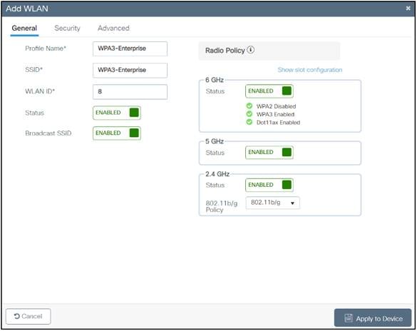
WLAN general setting
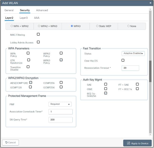
WLAN Layer 2 security settings
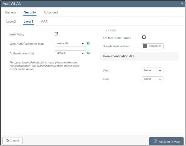
WLAN Layer 3 security settings
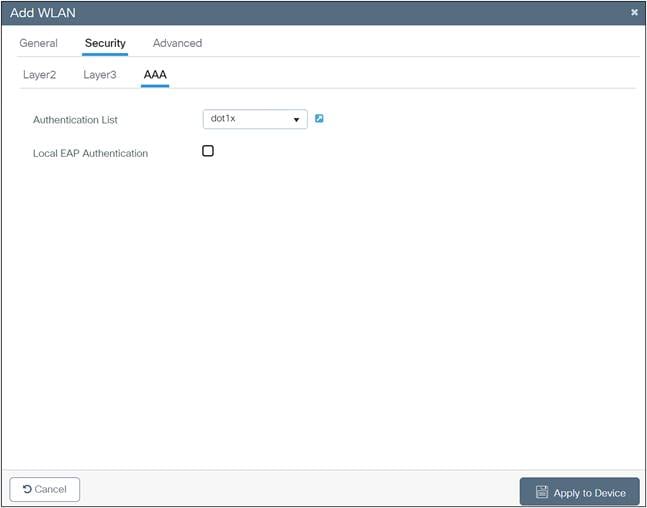
WLAN AAA settings
The WLC software provides local EAP authentication capability that can be used when an external RADIUS server is not available or becomes unavailable. When RADIUS server availability is restored, the WLC automatically switches back from local authentication to RADIUS server authentication.
The EAP types supported locally on the WLC are Lightweight EAP (LEAP), EAP Flexible Authentication via Secure Tunneling (EAP-FAST), EAP Transport Layer Security (EAP-TLS), and Protected EAP (PEAP).
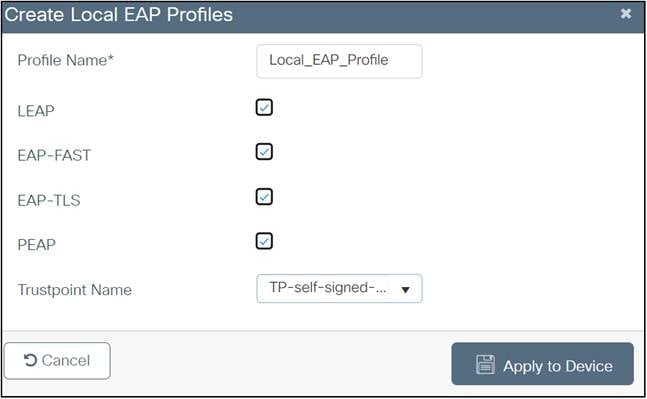
Local EAP profile
Figure 17 shows the window where you can select the local EAP profiles.
An Access Control List (ACL) is a set of rules used to limit access to a particular interface (for example, if you want to prevent a wireless client from pinging the Wireless Management Interface [WMI] of the controller). After ACLs are configured on the controller, they can be applied to the management VLAN, the WMI, any of the SVIs, or a WLAN to control data traffic to and from wireless clients.
You may also want to create a pre-authentication ACL for web authentication. Such an ACL could be used to allow certain types of traffic or a portal before authentication is complete.
Both IPv4 and IPv6 ACLs are supported. IPv6 ACLs support the same options as IPv4 ACLs, including source, and destination ports.
You can enable only IPv4 traffic in your network by blocking IPv6 traffic. That is, you can configure an IPv6 ACL to deny all IPv6 traffic and apply it on specific WLANs or all WLANs.
● You can define up to 64 ACLs, each with up to 64 rules (or filters) for both IPv4 and IPv6. Each rule has parameters that affect its action. When a packet matches all the parameters for a rule, the action set for that rule is applied to the packet.
● All ACLs have an implicit “deny all” rule as the last rule. If a packet does not match any of the rules, it is dropped by the controller.
● If you are using an external web server with a WLC or an Embedded Wireless Controller (EWC), you must configure a pre-authentication ACL on the WLAN for the external web server.
● If you apply an ACL to an VLAN or a policy, expect a slight degradation in the performance or throughput on the end devices.
● Multicast traffic received from wired networks that is destined to wireless clients is not processed by WLC ACLs. Multicast traffic initiated from wireless clients, and destined to wired networks or other wireless clients on the same controller, is processed by WLC ACLs.
● You can configure an ACL per client (AAA overridden ACL) or on either an interface or a policy. The AAA overridden ACL has the highest priority. However, each interface, WLAN, or per-client ACL configuration that you apply can override the others.
● If peer-to-peer blocking is enabled, traffic is blocked between peers even if the ACL allows traffic between them.
● Authentication traffic must go through the Cisco WLC for this feature to be supported, even if DNS-based ACL is local to the AP. When you create an ACL, we recommend performing the two actions (creating an ACL or ACL rule and applying the ACL or ACL rule) continuously, either from the CLI or GUI.
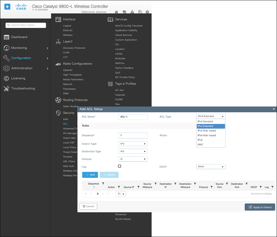
ACL configuration
Figure 18 displays the ACL configuration page. The ACL can specify source and destination address ranges, protocols, source and destination ports, Differentiated Services Code Point (DSCP), and the direction in which the ACL is to be applied. An ACL can be created out of a sequence of various rules.
The DNS-based ACLs are used for client devices such as Apple and Android devices. When using these devices, you can set pre-authentication ACLs on the Cisco WLC to determine where devices have the right to go.
To enable DNS-based ACLs on the Cisco WLC, you need to configure the allowed URLs for the ACLs. The URLs need to be preconfigured on the ACL.
With DNS-based ACLs, the client, when in the registration phase, is allowed to connect to the configured URLs.
The Cisco WLC is configured with the ACL name, and that is returned by the AAA server for the pre-authentication ACL to be applied. If the ACL name is returned by the AAA server, the ACL is applied to the client for web redirection.
At the client authentication phase, the ISE server returns the pre-authentication ACL (url-redirect-acl). The DNS snooping is performed on the AP for each client until the registration is complete and the client is in SUPPLICANT PROVISIONING state. When the ACL configured with the URLs is received on the Cisco WLC, the CAPWAP payload is sent to the AP, enabling DNS snooping on the client and the URLs to be snooped.
With URL snooping in place, the AP learns the IP address of the resolved domain name in the DNS response. If the domain name matches the configured URL, the DNS response is parsed for the IP address, and the IP address is sent to the Cisco WLC as a CAPWAP payload. The Cisco WLC adds the IP address to the allowed list of IP addresses, and thus the client can access the URLs configured.
Restrictions on DNS-based ACLs
● A maximum of 32 URLs is allowed for an ACL.
● For the Cisco WLC, 32 IP addresses are allowed for one client.
● Local authentication is not supported for FlexConnect APs.
● DNS-based ACLs are not supported on FlexConnect APs with local switching.
● Authentication traffic must go through the Cisco WLC to support this feature, even if the DNS-based ACL is local to the AP.
● If a client is anchored, whether auto-anchor or after roaming, DNS-based ACLs do not work.
● DNS-based ACLs work only when RADIUS Network Access Control (NAC) (central web authentication or posture) is done on the SSID. DNS-based ACLs do not work with local web authentication or any other form of ACL other than a redirect-ACL used in the case of RADIUS NAC.
The URL Filtering feature helps optimize network bandwidth utilization by restricting access to websites. It uses DNS snooping to snoop the DNS response sent from the DNS server to wireless clients. It is an ACL-based implementation to restrict URLs for all protocols, including HTTP and HTTPS. A URL Filtering ACL is defined as a set of URLs that are associated with allow/deny actions. This is defined under an ACL type, either a whitelist or a blacklist. A mix of whitelist and blacklist rules is not supported. The IP address of an external server is configured, which is used to redirect blocked pages if the configuration specifies that the access URL is to be blocked.
WLC snoops the DNS response for the client, and if the URL is allowed by the configuration (ACL rule), the DNS response will be sent to the client. If the URL is not allowed by the configuration (ACL rule), the resolved IP address will be overwritten with the external redirect server's IP address and returned to the client. This external server will redirect blocked page to the clients. Counters for allowed and denied DNS responses are viewable for an ACL as they are getting hit.
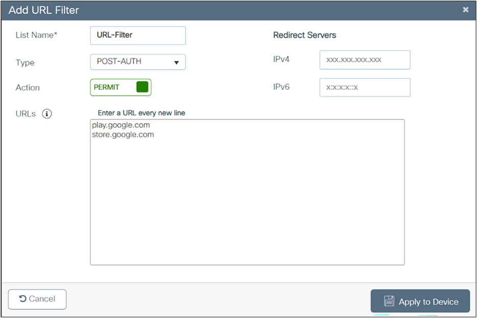
URL filter definition
ACLs are applied to a controller on a per-wireless-client basis. Typically, you can configure ACLs in a controller itself. However, you can also configure ACLs on a connected Cisco ISE server and download them to the controller when a wireless client joins. Such ACLs are referred to as downloadable ACLs, per-user dynamic ACLs, or dACLs.
Downloadable ACLs are easy to maintain because they define or update ACLs in Cisco ISE and can be downloaded to all the applicable controllers. (In Cisco IOS XE 17.8 and earlier releases, you had to configure the name in Cisco ISE and define the ACL individually in each of the controllers.)
Table 8. ACL scale for controllers
| Controllers |
ACL scale |
| Catalyst 9800-40 Wireless Controller (small or medium) |
Supports 128 ACLs with 128 ACEs |
| Catalyst 9800-80 Wireless Controller (large) |
Supports 256 ACLs and 256 ACEs |
Guidelines and restrictions for downloadable ACLs
● dACLs do not support FlexConnect local switching.
● IPv6 dACLs are supported only in Cisco ISE 3.0 or a later release.
● The dACL feature is supported only in a centralized controller in Local mode.
Cisco Umbrella® is a cloud-delivered network security service that gives insights to protect devices from malware and breach protection in real time. It uses evolving big data and data mining methods to proactively predict attacks and also does category-based filtering.
The following terminology is involved in the working of Cisco Umbrella:
API token is issued from the Cisco Umbrella Portal and is only used for device registration.
Device identity is a unique device identifier. Policy is enforced per identifier.
EDNS is an extension mechanism for DNS that carries tagged DNS packet.
FQDN is a fully qualified domain name.
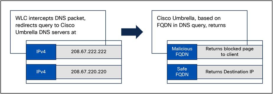
Cisco Umbrella’s handling of a DNS request
A DNS request always precedes a web request. The WLC intercepts a DNS request from the client and redirects the query to Cisco Umbrella in the cloud (208.67.222.222 or 208.67.220.220). Cisco Umbrella servers resolve the DNS query and enforce preconfigured security filtering rules on a per-identity basis to mark the domain as either malicious, which will return a blocked page to the client, or safe, returning the resolved IP address to client.
Umbrella filtering supported platforms
● All Cisco IOS XE based platforms.
● AP mode supported: Local mode, FlexConnect mode, and EWC.
● 10 different OpenDNS profiles configurable on the WLC.
● Guest (Foreign–Anchor) scenario; profile applies at the Anchor WLC.
Umbrella filtering limitations
● The client is connected to a web proxy and does not send a DNS query to resolve the server address.
● The application or host uses the IP address directly instead of using DNS to query domains.
The WLC can be configured to block communication between clients on the same WLAN. This prevents potential attacks between clients on the same subnet by forcing communication through the router.
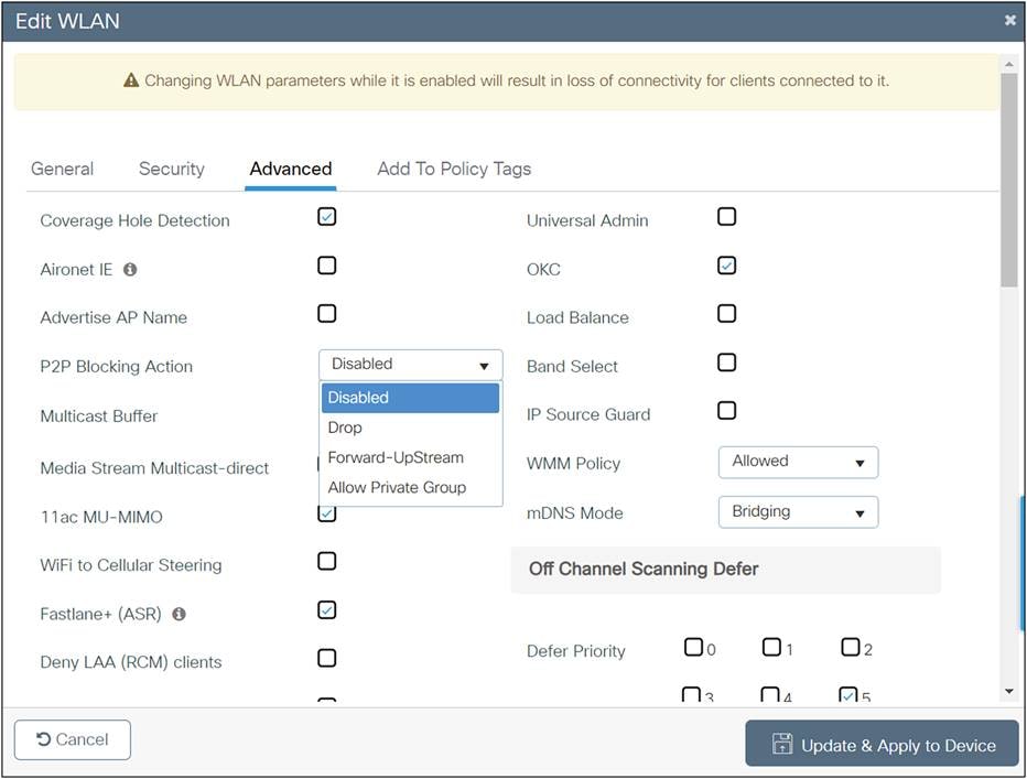
Peer-to-peer blocking action
Figure 21 is the configuration screen for peer-to-peer blocking on the WLC. Multiple blocking actions are available. These are:
● Disabled: P2P is disabled.
● Drop: P2P traffic is dropped.
● Forward-Upstream: The user traffic is forwarded to the next hop switch.
● Allow Private Group: This option works with iPSK clients. Only traffic between the same private group clients will be permitted.
When a user fails to authenticate, the controller can exclude the client. The client cannot connect to the network until the exclusion timer expires or is manually overridden by the administrator. This feature can prevent authentication server problems due to high load caused by intentional or inadvertent client security misconfiguration. It is advisable to always have client exclusion configured on all WLANs. Client exclusion can act as a protective mechanism for the AAA servers, as it will stop authentication request floods that could be triggered by misconfigured clients. Exclusion detects authentication attempts made by a single device. When the device exceeds a maximum number of failures, that MAC address is not allowed to associate any longer. The Catalyst 9800 Series wireless controllers exclude clients when any of the following conditions are met:
● Five consecutive 802.11 association failures.
● Three consecutive 802.1X authentication failures.
● IP theft or IP reuse, when the IP address obtained by the client is already assigned to another device.
● Three consecutive Web Authentication failures.
For more security best practices, see the Security Settings section of the Cisco Catalyst 9800 Series Configuration Best Practices: https://www.cisco.com/c/en/us/products/collateral/wireless/catalyst-9800-series-wireless-controllers/guide-c07-743627.html#Securitysettings.
Cisco aWIPS and Rogue Management
The Cisco aWIPS and Rogue Management solution offers a superset of capabilities not architecturally possible with standalone, overlay aWIPS and rogue management systems. The infrastructure-integrated architecture of Cisco aWIPS and Rogue Management allows network administrators to:
● See the whole picture: Typical aWIPS solutions rely solely on RF air monitoring for detection. Cisco aWIPS and Rogue Management builds on RF air monitoring by employing network traffic and anomaly analysis within the access points and WLAN controllers, as well as real-time device inventory analysis and network configuration analysis to detect threats and monitor performance. This approach delivers more accurate and thorough detection.
● Take corrective action: Cisco aWIPS and Rogue Management doesn't just detect threats, vulnerabilities, and performance issues; it makes it possible to take corrective action. Integration into the WLAN infrastructure enables aWIPS and Rogue Management to go beyond passive monitoring and reach into the infrastructure to fix security threats and performance issues in real time using containment.
● Take advantage of the entire WLAN footprint: Cisco aWIPS and Rogue Management can use all the APs in the network to locate and mitigate rogue devices. This increases location accuracy and mitigation scalability.
● Benefit from flexible deployment architectures: Cisco aWIPS and Rogue Management can use APs dedicated to full-time air monitoring or APs serving WLAN users or both. Deployment flexibility is provided by supporting multiple modes such as Local, FlexConnect central switching, FlexConnect local switching, SD-Access, etc. Cisco DNA Center allows you to group devices based on location, beginning by laying out a hierarchy of areas, buildings, and floors as required to accurately represent the location of your network. A site hierarchy lets you enable unique network settings and IP spaces for different groups of devices. This deployment flexibility enables right-sized security models on a site-specific basis.
This section has two main topics:
● Rogue detection and mitigation, describing Cisco solutions for detecting and disabling rogue access points and clients that could create backdoor access to the wireless network.
● aWIPS (Advanced Wireless Intrusion Prevention System), which deals with over-the-air attacks and their detection.
Rogue detection and mitigation
Wireless networks extend wired networks and increase worker productivity and access to information. However, an unauthorized wireless network presents an additional layer of security concern. Less thought is put into port security on wired networks, and wireless networks are an easy extension to wired networks. Therefore, an employee or a student who brings his or her own access point (Cisco or third party) into a well-secured wireless or wired infrastructure and allows unauthorized users access to this otherwise secured network can easily compromise a secure network.
Rogue detection allows the network administrator to monitor, detect, and eliminate this security concern. Cisco solutions provide methods for rogue detection that enable a complete rogue identification, classification, and containment solution without the need for expensive and hard-to-justify overlay networks and tools.
Any device that shares the wireless spectrum and is not managed by you can be considered to be a rogue.
Overview
A rogue becomes dangerous in these scenarios:
● When it is set up to use the same SSID as your network (honeypot).
● When it is detected on the wired network.
● When it is an ad hoc rogue.
● When it is set up by an outsider, usually with malicious intent.
The best practice is to use rogue detection to minimize security risks by detecting all kinds of attacks such as honeypot attacks, AP impersonation, FragAttacks, etc., in business-critical environments. However, there are certain scenarios in which rogue detection is not needed, for example, in Office Extend Access Point (OEAP) deployments and outdoors. The use of outdoor mesh APs to detect rogues would provide little value, while the analysis would use resources. Finally, it is critical to evaluate (or avoid altogether) rogue auto-containment, as there are potential legal issues and liabilities if left to operate automatically.
There are three main phases of rogue device management in the Cisco wireless solution:
● Detection: RRM scanning is used to detect the presence of rogue devices.
● Classification: Rogue classification rules assist in filtering rogues into specific categories based on their characteristics.
● Mitigation: Switch port shutting, rogue location, and rogue containment are used in to track down its physical location and to nullify the threat of the rogue device.
Rogue detection
A rogue is essentially any device that shares your spectrum but is not in your control. This includes rogue APs, wireless router, rogue clients, and rogue ad-hoc networks. The Cisco wireless solution uses several methods to detect Wi-Fi-based rogue devices, such as off-channel scanning, dedicated monitor mode capabilities, and a custom RF ASIC. Cisco wireless innovation, such as Cisco CleanAir, can be used to identify rogue devices not based on the 802.11 protocol, such as Bluetooth bridges.
Rogue classification
By default, all rogues that are detected by the Catalyst 9800 Series WLCs are considered unclassified. As shown in the figure below, rogues can be classified based on a number of criteria that include RSSI, SSID, security type, whether it is on or off the network, and number of clients.
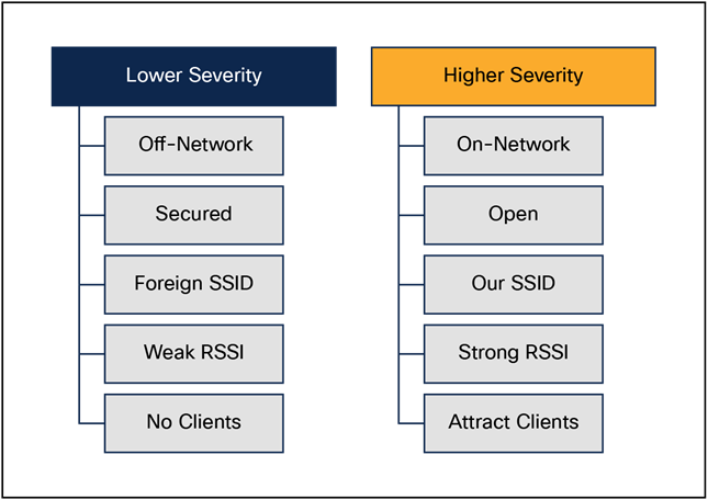
Rogue classification
Rogue mitigation
Containment is a method that uses over-the-air packets to temporarily interrupt service on a rogue device until it can physically be removed. Containment works by sending deauthentication packets with the spoofed source address of the rogue AP so that any clients associated with it are kicked off.
A rogue AP can be contained either automatically or manually. The controller selects the best available access point for containment and pushes the information to the access point. The access point stores the list of containments per radio. The container AP goes through the list of containments periodically and sends containment frames. Rogue containment can be performed from a WLC or Cisco DNA Center. Containment in 6 GHz is not supported, as the WLANs are Protected Management Frame (PMF) enabled.
aWIPS
aWIPS overview
aWIPS protects against advanced attacks by detecting threats based on anomalies in the device’s behavior. It provides security against Denial-of-Service (DoS) attacks, tool-based attacks, and more.
The Cisco aWIPS and Rogue Management solution comprises Cisco APs, WLCs, and Cisco DNA Center. The solution is supported on all 802.11ax/802.11ac Wave 2 Cisco APs and the Catalyst 9800 Series.
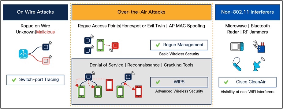
Detection of rogue devices and APs
An AP enabled for aWIPS scans for and detects threats using signature-based techniques and contains rogue APs and ad hoc networks.
APs can operate in Monitor, Local, and FlexConnect mode. In Monitor mode, the radios continuously scan all channels for any threats, but they don’t serve any clients. In Local and FlexConnect modes, AP radios serve clients and scan for threats on client-serving channels. On non-serving channels they do best-effort scanning for any possible threats.
With the Catalyst 9130 and 9120 Series Wi-Fi 6 APs, there is an additional custom RF ASIC radio that continuously monitors all channels for any threats, while the other radios serve the clients. With this dedicated radio, we significantly improve our threat detection capabilities.
For more information on rogues and aWIPS, refer to the following chapters of the Cisco Catalyst 9800 Series Wireless Controller Software Configuration Guide:
Managing Rogue Devices:
Classifying Rogue Access Points:
Advanced WIPS:
Like the Catalyst 9120 and 9130 Series APs, the Catalyst 9136, 9162, 9164, and 9166 access points have an additional radio that monitors all the channels for threats, while the other radios serve the clients. This radio has scanning capabilities in all three bands, 2.4 GHz, 5 GHz, and 6 GHz. With this dedicated radio, we can significantly improve out threat detection capabilities. These scanning radios use a multiradio architecture and can perform AI/ML-driven scanning, decoding of High-Efficiency (HE) frames, and ML-based interferer classification on the AP.
Cisco TrustSec® enables organizations to secure their networks and services through identity-based access control for anyone, anywhere, anytime. The solution also offers data integrity and confidentiality services, policy-based governance, and centralized monitoring, troubleshooting, and reporting services. TrustSec can be combined with personalized, professional service offerings to simplify solution deployment and management, and is a foundational security component of a Cisco wireless network.
The Cisco TrustSec security architecture builds secure networks by establishing domains of trusted network devices. Each device in the domain is authenticated by its peers. Communication on the links between devices in the domain is secured with a combination of encryption, message integrity check, and data-path replay protection mechanisms. Cisco TrustSec uses the device and user credentials acquired during authentication for classifying the packets by security groups as they enter the network. This packet classification is maintained by tagging packets on ingress to the Cisco TrustSec network so that they can be correctly identified to apply security and other policy criteria along the data path. The tag, called the Security Group Tag (SGT), allows the network to enforce the access control policy by enabling the endpoint device to act upon the SGT to filter traffic. Cisco TrustSec SGTs are applied only when you enable AAA override on a WLAN.
One of the components of the Cisco TrustSec architecture is security group-based access control. In this component, access policies in the Cisco TrustSec domain are topology-independent, based on the roles (as indicated by security group number) of the source and destination devices rather than on network addresses. Individual packets are tagged with the security group number of the source.
Cisco devices use the SGT Exchange Protocol (SXP) to propagate SGTs across network devices that do not have hardware support for Cisco TrustSec. SXP is the software solution to avoid a Cisco TrustSec hardware upgrade on all switches. WLCs support SXP as part of the TrustSec architecture. SXP sends SGT information to the Cisco TrustSec-enabled switches so that appropriate Role-Based Access Control Lists (RBACLs) can be activated depending on the role information represented by the SGT. By default, the controller always works in Speaker mode. To implement SXP on a network, only the egress distribution switch needs to be Cisco TrustSec-enabled, and all the other switches can be non-TrustSec-capable switches.
SXP runs between any access layer and distribution switch or between two distribution switches. It uses TCP as the transport layer. TrustSec authentication is performed for any host (client) joining the network on the access layer switch such as an access switch with TrustSec-enabled hardware. The access layer switch is not TrustSec hardware enabled. Therefore, data traffic is not encrypted or cryptographically authenticated when it passes through the access layer switch. SXP is used to pass the IP address of the authenticated device — that is, a wireless client —and the corresponding SGT up to the distribution switch. If the distribution switch is TrustSec hardware enabled, the switch inserts the SGT into the packet on behalf of the access layer switch. If the distribution switch is not TrustSec hardware enabled, the SXP on the distribution switch passes the IP-SGT mapping to all the distribution switches that have TrustSec hardware. On the egress side, the enforcement of the RBACL occurs at the egress Layer 3 interface on the distribution switch.
The following are some guidelines for Cisco TrustSec SXP:
● SXP is supported on the following security policies only:
◦ WPA2-dot1x
◦ WPA3-dot1x
◦ MAC filtering using RADIUS servers
◦ Web authentication using RADIUS servers for user authentication
● Security Group Access Control List (SGACL) enforcement is carried out on the controller for Local mode.
● SGACL enforcement is carried out on an AP for Flex mode APs performing local switching.
● SGACL enforcement for wireless clients is carried out either on the upstream switch or on the border gateway in a branch-to-data center scenario.
● SGACL enforcement is not supported for non-IP or IP broadcast or multicast traffic.
● Per-WLAN SGT assignment is not supported.
● SGACL enforcement is not carried out for control-plane traffic between an AP and the wireless controller (for upstream or from upstream traffic).
● Non-static SGACL configurations are supported only for dynamic SGACL policies received from ISE.
● Static SGACL configuration on an AP is not supported.
For more information, refer to the Cisco TrustSec chapter of the Cisco Catalyst 9800 Series Wireless Controller Software Configuration Guide:
Implementation
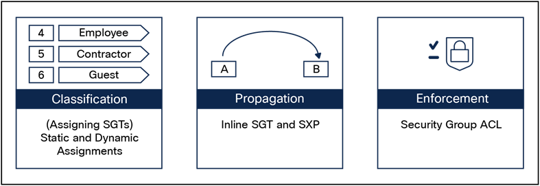
Cisco TrustSec implementation
Every endpoint that touches the TrustSec domain gets classified by ISE based on end user identity such as role, device type, and other client attributes and is associated with a unique SGT that is shared with the device that requested the client authentication upon successful authentication. This allows grouping of clients based on client identity attributes, thereby considerably reducing the number of Access Control Entities (ACE). A major benefit of SGACL use is the consolidation of ACEs and the operational savings involved with maintenance of those traditional access lists.
The TrustSec solution is realized across three distinct phases within the TrustSec domain.
● Client classification at ingress by a centralized policy database (ISE) and assigning a unique SGT to the client based on client identity attributes.
● Propagation of IP-to-SGT binding to neighboring devices using SXPv4 and/or inline tagging methods.
● SGACL policy enforcement. The AP will be the enforcement point for central and local switching (central authentication).
TrustSec PAC provisioning and device enrollment
Any device that participates in the Cisco TrustSec network must be authenticated and trusted. To facilitate the authentication process, new devices connected to the TrustSec network undergo an enrollment process wherein the device obtains the credentials that are specifically needed for TrustSec device authentication and obtain general TrustSec environment information.
The WLC device enrollment is initiated by the WLC as part of Protected Access Credentials (PAC) provisioning with the ISE server. The WLC initiates EAP-FAST and obtains a PAC. This is accomplished by a using the infrastructure of LOCAL-EAP EAP-FAST PAC provisioning. The PAC obtained uniquely maps to the device ID. If the device ID changes, PAC data associated with the previous device ID is removed from the PAC store. PAC provisioning is triggered when a RADIUS server instance is enabled to provision the PAC.
In the case of High Availability (HA) setup, PACs will be synced to the standby box.
Environment data
Cisco TrustSec environment data is a set of information or attributes that helps the device to perform TrustSec-related functions.
The device acquires the environment data from the authentication server when the device first joins a Cisco Trust Sec domain by sending a secure RADIUS access-request. The authentication server returns RADIUS access-accept with attributes including environment expiration timeout attributes. This time interval controls how often the Cisco Trust Sec device must refresh its environment data.
Inline tagging
Inline tagging functionality is a transport mechanism by which a wireless controller or an access point understand the source SGT (S-SGT). It covers the following two types.
● Central switching: For centrally switched packets, the WLC performs inline tagging for all packets sourced from wireless clients that reside on the WLC by tagging it with a Cisco MetaData (CMD) tag. For packets inbound from the DS, inline tagging also involves the WLC stripping the packet of the header and sending it to the AP over CAPWAP for the AP to learn the S-SGT tag. SGACL enforcement will happen at the AP.
● Local switching: For transmitting, the locally switched traffic AP performs inline tagging for packets sourced from clients that reside on the AP. When receiving traffic, the AP will handle both locally switched and centrally switched packets, using the S-SGT tag for packets and applying the SGACL policy.
With wireless TrustSec enabled on the WLC, the choice of also enabling and configuring SXP to exchange tags with the switches is optional, and both modes — SXP speaker mode and inline tagging — are supported; however, there is no use case to have both SXP and wireless TrustSec on an AP to be enabled simultaneously.
Propagation and enforcement
There are two modes for SGT propagation:
SXP
SXP is a control protocol that propagates an IP address to SGT binding information across network devices. Using the SGT and SGACL information, the endpoint device (WLC or AP) can enforce traffic.
Central switching
The WLC can act as listener, speaker, or both. In Listener mode, the WLC can enforce traffic, whereas a WLC in both modes can enforce as well as propagate SGT information to the enforcement point.
An important difference between the Cisco 8540 Wireless Controller and the Catalyst 9800 Series controllers in a central switching deployment is that on the 8540, enforcement happens on the AP. On the Catalyst 9800 Series, enforcement happens on the WLC.
Local switching
The AP acts as listener, speaker or both. In Listener mode, the AP can enforce traffic. When the AP is in both modes, it can enforce and propagate SGT information to the enforcement point. This functionality is the same between 8540 and Catalyst 9800 Series deployments.
Inline tagging
Inline tagging involves tagging each packet egressing the controller by inserting a CMD header.
For inbound packets (toward the client), the CMD header is stripped if present. The client S-SGT is used to find the SGACL associated with (S-SGT, D-SGT) for enforcement.
Central switching and inline tagging
The WLC performs inline tagging for all packets sourced from wireless clients. For inbound traffic (toward the client), the WLC strips the CMD header and learns the SGT information from the metadata header. The WLC will enforce the traffic using the SGT information.
Local switching and inline tagging
The AP performs inline tagging for all packets sourced from wireless clients that reside on the AP by tagging them with a CMD tag. For inbound packets (toward the client), the AP will strip the CMD header and act as an enforcement point. This functionally is the same between 8540 and Catalyst 9800 Series deployments.
In a nutshell, propagation and enforcement happen on the WLC or AP, depending on the deployment method (central or flex local switching) and the type of controller (Catalyst 9800 Series or 8540) deployed in the network.
Encrypted Traffic Analytics (ETA) leverages Flexible NetFlow (FNF) technology to export useful information about the flow to the collectors and gain visibility into the network.
The wireless clients send data packets to the access point. The packets are then CAPWAP encapsulated and sent to the controller. This means that the actual client data is in the CAPWAP payload. To apply ETA to the client data, you need to strip the CAPWAP header before handing over the packet to the ETA module.
ETA offers the following advantages:
● Enhanced telemetry-based threat analytics
● Analytics to identify malware
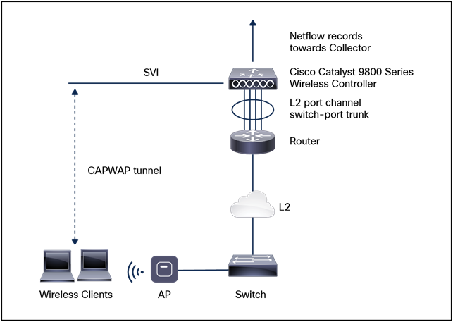
Encrypted Traffic Analytics on a Catalyst 9800 WLC in Local mode
Starting from Cisco IOS XE Amsterdam 17.1.1s, ETA inspection for IPv6 traffic is supported. ETA inspection of IPv6 traffic is enabled by default, and no special configuration is required. This release also supports a list of allowed IPv6 traffic, exporting ETA records to an IPv4 or IPv6 export destination, exporting records over IPFIX (NetFlow v10), and configuring a source interface for ETA exports. The records can be exported to an IPv4 or IPv6 NetFlow collector.
For more information on the ETA configuration, refer to the Encrypted Traffic Analytics chapter of the Cisco Catalyst 9800 Series Wireless Controller Software Configuration Guide: https://www.cisco.com/c/en/us/td/docs/wireless/controller/9800/config-guide/b_wl_16_10_cg/encrypted-traffic-analytics-on-software-defined-access-sda-wireless.html.
High availability has been a requirement on WLCs to minimize downtime in live networks. This section describes the theory of operation and configuration for Catalyst 9800 Series WLCs as it pertains to supporting stateful switchover of Access Points and clients (AP and client SSO). The Catalyst 9800 Series is the next generation in wireless controllers and can run on multiple platforms with different scalability goals, from low to high scale. AP and client SSO is supported on the physical appliances and the virtual cloud platforms of the Catalyst 9800 Series, namely the 9800-L, 9800-40, 9800-80, and 9800-CL. The underlying SSO functionality is the same on all platforms, with some differences in the setup process.
The high availability SSO capability on WLCs allows the AP to establish a CAPWAP tunnel with the active WLC and the active WLC to share a mirror copy of the AP and client database with the standby WLC. The APs do not go into the discovery state, and clients do not disconnect when the active WLC fails and the standby WLC takes over the network as the active WLC. Only one CAPWAP tunnel is maintained at a time between the AP and the wireless controller that is in an active state. Release 16.10 supports full AP and client SSO. Client SSO is supported for clients that have already completed the authentication and DHCP phase and have started passing traffic. With client SSO, a client's information is synced to the standby WLC when the client associates to the WLC or the client’s parameters change. Fully authenticated clients, that is, the ones in the run state, are synced to the standby WLC, and thus client reassociation is avoided on switchover, making the failover seamless for the APs as well as for the clients, resulting in zero client service downtime and zero SSID outage. The overall goal in adding AP and client SSO support to the Catalyst 9800 Series WLCs is to reduce major downtime in wireless networks due to failure conditions that may occur due to box failover, network failover, or a power outage at the primary site.
All control plane activities are centralized and synchronized between the active and standby units. The active controller centrally manages all the control and management communication. The network control data traffic is transparently switched from the standby unit to the active unit for centralized processing.
Bulk and incremental configuration is synced between the two controllers at run-time, and both controllers share the same IP address on the management interface. The CAPWAP state of the APs that are in the run state is also synced from the active WLC to the hot-standby WLC, allowing the APs to be statefully switched over when the active WLC fails. The APs do not go to the discovery state when the active WLC fails and the standby WLC takes over as the active WLC to serve the network.
The two units form a peer connection through a dedicated Redundancy Port (RP) (this can be a physical copper or fiber port) or a virtual interface for the VM. The active/standby election happens at boot time, and it’s based on either the highest priority (the priority range is <1-2>) or the lowest MAC if the priority is the same. By default, the Catalyst 9800 Series has a priority of 1. Once the HA pair is formed, all the configuration and AP and client databases are synced between active and standby. Any configuration done on the active is automatically synced to the standby. The standby is continuously monitoring the active via keep-alive messages over the RP link. If the active becomes unavailable, the standby assumes the role of active. It does that by sending a Gratuitous ARP message advertising to the network that it now owns that wireless management IP address. All the configurations and databases are already in sync, so the standby can take over without service disruption.
● Cisco Catalyst C9800-40 Wireless Controller
● Cisco Catalyst C9800-80 Wireless Controller
● Cisco Catalyst C9800-CL Wireless Controller
● Cisco Catalyst C9800-L Wireless Controller
● An HA pair can be formed only between two wireless controllers of the same form factor.
● Both controllers must be running the same software version to form an HA pair.
● Maximum RP link latency is 80 ms Round-Trip Time (RTT), minimum bandwidth is 60 Mbps, and the Maximum Transmission Unit (MTU) must be at least 1500.
Controller patching using Software Maintenance Updates (SMU)
An SMU is a package that can be installed on a system to provide a patch fix or security resolution to an already released image. An SMU package is provided on a per-release and per-component basis and is specific to the platform.
There are two types of SMUs, those that can be hot-patched and those that can only be cold-patched.
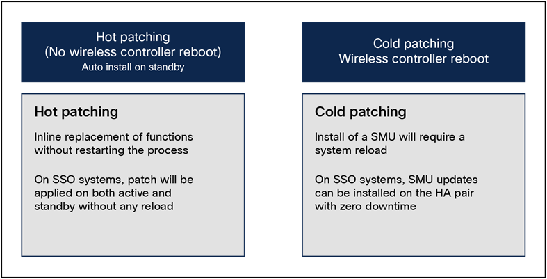
Types of software maintenance updates
A hot patch does not need a system reload, which means the clients and APs will not be affected. When the controller is part of an HA pair, the SMU activation applies to both the active and hot-standby controllers.
A cold patch, on the other hand, requires a reload. However, since we are looking for a seamless, zero-downtime update, an SSO pair can be used to install a cold patch without bringing the network down.
Figure 27 shows the process of installing a cold patch on an SSO pair.
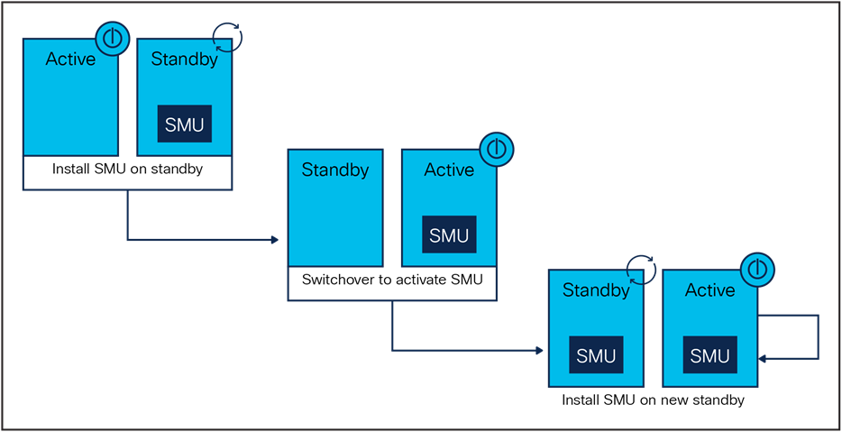
Active-standby cold patch activation
The system will install the SMU on the standby controller and reload the standby. The network is still running because the APs and clients are on the active controller. Once the standby is up, a switchover occurs, pushing all AP and client sessions to the new active controller (formerly the standby). At this point the SMU is installed on the new standby (which was the old active controller). Both controllers have now been updated with the SMU.
Note: SMUs are released only on long-lived MD releases, which means controller SMUs will be available starting with the first MD release, 16.12.
Rolling AP update infrastructure
The Cisco Catalyst 9800 Series supports rollouts of critical AP bug fixes using an AP Service Pack (APSP). When APs need to be upgraded to the new image, the 9800 Series supports doing so in a staggered fashion, such that an appropriate number of APs are always up and running in the network and providing RF coverage to clients. This is referred to as a rolling AP upgrade.
The AP service pack, which is for AP-specific fixes, will be independent of the SMU timeline and will be available on non-MD releases as well after Release 16.10.
Three main highlights to this feature are:
● Rolling updates are supported natively on the wireless controller using the UI or CLI.
● Rolling updates support automatic candidate selection using the RRM- based AP neighbor information. The device auto-selects the candidate APs to be upgraded in each iteration based on a chosen percentage per iteration (5%, 15%, or 25%, with the default being 15%) and RRM AP neighbor information.
● Clients from candidate APs are actively steered away using 802.11v packets with the “dissociation imminent” field set to help ensure seamless network connectivity as APs are being upgraded. If clients do not honor this setting, they will be de-authenticated before AP reload.
Per-site AP service pack rollout
At the time of AP service pack activation, the user selects the sites where the AP service pack should be rolled out. All APs on these sites will be updated with the designated service pack, including any new APs that join the site after the filter is applied. This allows the user to control the propagation of a service pack in the network.
It should be noted that this enhancement allows for activating service packs on sites incrementally but requires that all sites be brought to the same service pack level before a new service pack can be rolled out to a subset of sites.
Per-AP-model service pack rollout
An AP service pack can also be built with a subset of AP images. These enable a pre-download only to the affected AP models. Similarly, these service packs are activated only on the AP models affected, in conjunction with any site-based filters, as mentioned earlier.
Again, it should be noted that if, for example, three model images were included in an AP service pack, all future AP service packs in that release for any of these three AP images will contain all three of them. This helps subsequent service packs to supersede older ones.
These two capabilities work in conjunction with each other, meaning that you can select specific sites in a campus and then apply the fix to specific AP models within those sites, as designated by the service pack. This enables controlled propagation of the fix with minimal or no service disruption because the fix is predownloaded and rolled out only to affected AP models.
In-Service Software Upgrade (ISSU) is a procedure to upgrade a WLC image to a later release while the network continues to forward packets. ISSU helps network administrators avoid a network outage when performing a software upgrade.
ISSU can also be used to apply cold patches without impacting the active network.
ISSU is supported only on the following Catalyst 9800 Series WLCs and supports only upgrade.
● Cisco Catalyst 9800-80 Wireless Controller
● Cisco Catalyst 9800-40 Wireless Controller
● Cisco Catalyst 9800-L Wireless Controller
● Cisco Catalyst 9800-CL Wireless Controller (private cloud)
High-level workflow of ISSU
1. Onboard the controller software image to the flash memory.
2. Download the AP image to the AP.
3. Install the controller software image.
4. Commit the changes.
Prerequisites for performing ISSU
● Ensure that both active and standby WLCs are in install mode and are booted from bootflash:packages.conf.
● Ensure that the network or device is not being configured during the upgrade.
● Schedule the upgrade when your network is stable and steady.
● Ensure an uninterrupted power supply. A power interruption during the upgrade procedure might corrupt the software image.
● If you do not run the install commit command within 6 hours of the install activate ISSU command, the system will revert to the original commit position. You can choose to delay the commit using the Upgrading Software Using ISSU with Delayed Commit procedure.
● During an ISSU upgrade, while the AP rolling upgrade is in progress, the install abort command won’t work. To cancel the upgrade, you should instead use the install abort ISSU command.
● During an ISSU upgrade, the system displays a warning message, such as “found 46 disjoint TDL objects.” You can ignore the warning message because it doesn’t have any functional impact.
● During an ISSU upgrade, if both controllers (active and standby) have different images after the power cycle, the ISSU is automatically canceled to bring both the controllers to the same version. The following is a sample scenario: Install Version1 (V1) software on the active controller and then apply an SMU hot patch and perform a commit. Now upgrade the software to Version2 using ISSU, and then power cycle the active controller. At this point, the system has a version mismatch (V1 and V2). The active controller reloads at this stage, after the completion of bulk synchronization. Now, both controllers come up with the same version (V1 and V1).
● An ISSU upgrade that is canceled because of configuration synchronization failure on the standby controller rolls back to V1 of the software image. However, this information isn’t available in the show install command log. Run the show ISSU state detail command to see the current ISSU state.
● To enable the clear install command, you should first run the service internal command in global configuration mode, and then run the clear install command in privileged EXEC mode.
● Image rollback could be affected if the controller has a stale rollback history and the stack gets formed afterward. We recommend that you run the clear install state command to clear stale information and boot the controller in bundle mode.
● The clear install state command doesn’t clear an added SMU. To remove an SMU, use either the install remove file command, or the install remove inactive command.
● When the new active controller comes up after the image upgrade, it doesn’t retain the old logs on the web GUI window as part of show logs.
● If an SSO or HA event occurs during the rolling AP upgrade procedure of the ISSU feature, the rolling AP upgrade stops. You should then use the ap image upgrade command to restart the upgrade process.
● If HA fails to form after the ISSU procedure, you should reload any one chassis again to form HA again.
● When you use ISSU to downgrade the controller image to version 1 (V1) after upgrading from controller version 1 (V1) and AP Service Pack version 1 (APSP1) to controller version 2 (V2) and AP Service Pack version 2 (APSP2), the wrong image may get pushed to the AP. In such instances, remove APSP1 and reinstall it. After that, APSP1 images are pushed to the AP.
● Use the clear ap pre-download statistics command before using the show AP image command. This ensures that you get the right data after every predownload.
● Manually cancel the ISSU process using the install ISSU abort command in the scenarios given below, to avoid a software version mismatch between the active controller and the standby controller.
● An RP link is brought down after standby HOT during an ISSU procedure and the links remains down even after the auto-abort timer expires.
● An RP link is brought down before the standby controller reaches standby HOT during an ISSU procedure.
● Cisco TrustSec is not supported on the Remote Method Invocation (RMI) interfaces.
● If a switchover occurs while performing an AP upgrade using ISSU, the upgrade process will restart automatically after the switchover.
Site-based rolling AP upgrade in N+1 networks
Starting with Release 17.9.1, the Catalyst 9800 Series supports site-based rolling AP upgrades in N+1 networks. This allows you to perform a staggered upgrade of APs in each site in an N+1 deployment.
Note: The N and the N+1 can be a HA pair.
This feature helps you to effectively achieve a zero-downtime network upgrade in an N+1 network. The existing site filter functionality allows you to perform a software upgrade of a site or of all the sites managed by the controller.
In a typical scenario, the software of the APs belonging to a site is upgraded and the network is monitored to see whether it is functioning as intended before adding more sites to the site filter. If the upgrade fails to meet the objectives, all the sites in the site filter can be removed using the ap image site-filter file any-image remove-all command. The ap image site-filter command is modified to include the any-image keyword as a substitute for the image filename to support the N+1 AP move site filter.
Prerequisites for site-based rolling AP upgrade in N+1 networks
● The source and destination controllers should be in the same mobility group (preferably running the latest image) but with different AP image versions.
● The image of the destination controller should be available on the source controller.
● Both the source and destination controllers should be in INSTALL mode.
Restrictions for site-based rolling AP upgrade in N+1 networks
● Site filter operations are supported only for N+1 upgrade and N+1 move; the fallback and reset options of the ap image upgrade destination command are not supported.
● APs can move only across controllers having the same software.
● The any and remove-all keywords of the ap image site-filter command work only for the N+1 AP upgrade or move. They will not work for other site filter operations such as AP Model Service Pack (APSP) or AP Device Package (APDP).
● A reboot of the source or destination controller during the N+1 upgrade requires reexecution of the procedure.
For more information on N+1 site-based rolling AP upgrade, see the Site-Based Rolling AP Upgrade in N+1 Networks chapter of the Cisco Catalyst 9800 Series Wireless Controller Software Configuration Guide: https://www.cisco.com/c/en/us/td/docs/wireless/controller/9800/17-9/config-guide/b_wl_17_9_cg/m_site_ap_upgr_nplus1.html.
Beginning with Cisco IOS XE Amsterdam 17.2.1, multichassis link aggregation group (multi-LAG), which provides flexibility in connecting the controller to a switch's infrastructure, is supported. Using multi-LAG, you can connect the multiple uplinks from the controller to the separate uplink switches. The controller supports VLAN-based traffic splitting when connected to a multiswitch topology. This provides the ability to distribute traffic on different uplinks based on VLANs, for example, supporting a use case in which guest traffic can be completely isolated to a different switch or network from the enterprise network. The same VLAN cannot be configured on both the uplinks.
You can connect a LAG to a single switch. However, different VLANs must be connected to different LAGs. The redundancy port must be connected to the same distribution switch as the uplinks, or back to back.
Multi-LAG is supported in LAG ON, Link Aggregation Control Protocol (LACP), and Port Aggregation Protocol (PAgP) modes.
● Each LAG must be connected to a single switch.
● Different VLANs must be assigned to different LAGs.
● If the primary LAG fails, automatic failover to the secondary LAG is not supported.
● The interface on the controller does not come up when you shut or open the port on the switch.
The Catalyst 9800-80 WLC has eight ports, while the Catalyst 9800-40 and 9800-L WLCs have four ports each. You can create multi-LAGs of ports with similar capabilities, for example, 2.5 G and 2.5 G, or 10 G and 10 G. You cannot have a 2.5 G and a 10 G port in a port channel group with a minimum of two ports in one LAG.
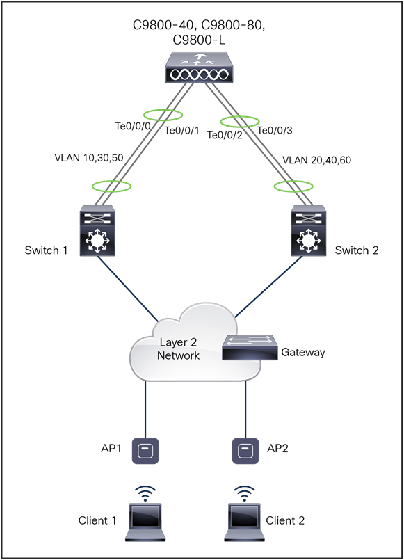
Single controller with multi-LAG
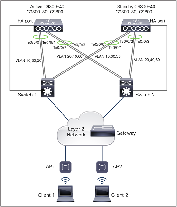
SSO pair with multi-LAG
Quality of service refers to the capability of a network to provide differentiated service to selected network traffic over various networks. QoS technologies provide the following benefits:
● Provide building blocks for business multimedia and audio applications used in campus, WAN, and service provider networks.
● Allow network managers to establish Service-Level Agreements (SLAs) with network users.
● Enable network resources to be shared more efficiently and expedite the handling of mission-critical applications.
● Manage time-sensitive multimedia and audio application traffic to ensure that this traffic receives higher priority, greater bandwidth, and less delay than best-effort data traffic.
With the help of QoS, bandwidth can be managed more efficiently across WLANs, LANs, and WANs. QoS provides enhanced and reliable network service by doing the following:
● Supporting dedicated bandwidth for critical users and applications.
● Controlling jitter and latency (required by real-time traffic).
● Managing and minimizing network congestion.
● Shaping network traffic to smooth the traffic flow.
● Setting network traffic priorities.
In the past, WLANs were mainly used to transport low-bandwidth, data application traffic. Currently, with the expansion of WLANs into industries (such as healthcare, finance, and education) and enterprise environments, WLANs are used to transport high-bandwidth data applications in conjunction with time-sensitive multimedia applications. This requirement has led to the necessity for wireless QoS.
Several vendors, including Cisco, support proprietary wireless QoS schemes for audio applications. A Catalyst approach to wireless QoS is necessary to speed up the rate of QoS adoption and support multivendor time-sensitive applications. The IEEE 802.11e working group within the IEEE 802.11 standards committee has completed the standard definition and adopted the 802.11e standard. As with many standards, there are many optional components. Just as with 802.11 security in 802.11i, industry groups such as the Wi-Fi Alliance and industry leaders such as Cisco are defining the key requirements in WLAN QoS through their WMM and Cisco Compatible Extensions programs, ensuring the delivery of key features and interoperation through their certification programs.
Cisco Catalyst wireless products support Wi-Fi Multimedia (WMM), a QoS system based on IEEE 802.11e published by the Wi-Fi Alliance, and WMM Power Save, as well as Admission Control.
Figure 30 shows an example of the WMM upstream and downstream traffic flow of QoS-based Cisco Catalyst wireless solutions.
Traffic from the infrastructure through the WLC and AP down to the endpoint device is considered downstream or egress traffic, and traffic from the wireless clients flowing through the AP and Cisco WLC toward the infrastructure is termed upstream or ingress traffic.
Here the flow is depicted as a RED dotted line for egress traffic, which resembles video-type streaming. This will be downstream traffic from the video server to an endpoint.
The GREEN solid line depicts both directions of traffic, such as a voice call between a VoIP phone and a mobile device that caters to bidirectional traffic. The QoS marking is done both at the WLC and AP in both directions based on policy configuration.
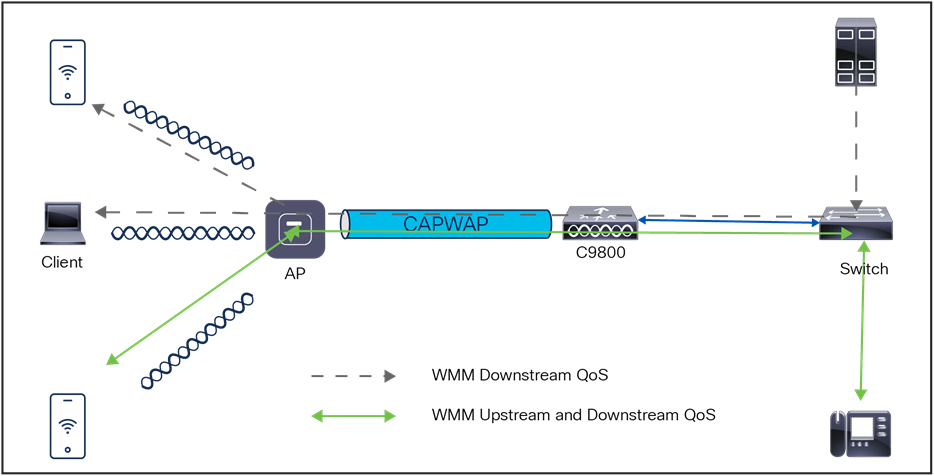
QoS ingress and egress traffic flow
QoS is defined as the measure of end-to-end network transmission quality. Transmission quality is determined based on network latency, jitter, and loss, defined in Table 9.
QoS controls and manages network resources by setting priorities for specific data types on the network.
Table 9. QoS transmission quality
Radio upstream and downstream QoS
Figure 31 illustrates the concepts of radio upstream and radio downstream QoS.
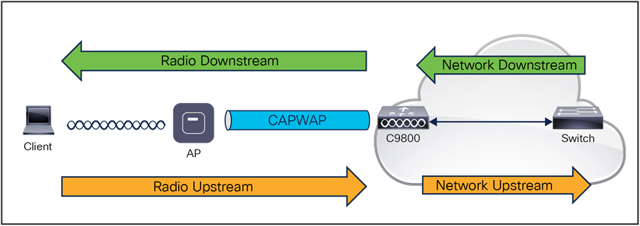
Downstream and upstream QoS
As illustrated in Figure 31:
● Radio downstream/egress traffic: Traffic leaving the AP and traveling to the WLAN clients. Radio downstream QoS or egress flow is the primary focus of this chapter because this is still the most common deployment. The radio client upstream QoS depends on the client implementation.
● Radio upstream/ingress traffic: Traffic leaving the WLAN clients and traveling to the AP. WMM provides upstream QoS for WLAN clients supporting WMM.
● Network downstream: Traffic leaving the WLC and traveling to the AP. QoS can be applied at this point to prioritize and rate-limit traffic to the AP.
● Network upstream: Traffic leaving the AP and traveling to the WLC. The AP classifies traffic from the AP to the upstream network according to the traffic classification rules of the AP.
The application of QoS features could be difficult to detect on a lightly loaded network. If latency, jitter, and loss are noticeable when the media is lightly loaded, it indicates either a system fault, poor network design, or that the application’s latency, jitter, and loss requirements are not a good match for the network. QoS features start to be applied to application performance as the load on the network increases. QoS works to keep latency, jitter, and loss for selected traffic types within acceptable boundaries. Radio upstream client traffic is treated as best effort when providing only radio downstream QoS from the AP. A client must compete with other clients for upstream transmission as well as competing with best-effort transmission from the AP. Under certain load conditions, a client can experience upstream congestion, and the performance of QoS-sensitive applications might be unacceptable despite the QoS features on the AP. Ideally, upstream, and downstream QoS can be operated either by using WMM on both the AP and WLAN client or by using WMM and a client proprietary implementation.
WLAN client support for WMM does not mean that the client traffic automatically benefits from WMM. Instead, the applications looking for the benefits of WMM assign an appropriate priority classification to their traffic, and the operating system needs to pass that classification to the WLAN interface. This is done as part of the design of purpose-built devices, such as VoWLAN handsets. However, if implemented on a general-purpose platform such as a PC, application traffic classification and OS support must be implemented before the WMM features can be used to good effect.
Even without WMM support on the WLAN client, the Catalyst wireless network solution can provide network prioritization in both network upstream and network downstream situations.
802.11e, 802.1P, and DSCP mapping
WLAN data in a Catalyst wireless network is tunneled by way of CAPWAP (IP UDP packets). To maintain the QoS classification that has been applied to WLAN frames, the WLC uses a process of mapping classifications to and from DSCP and Class of Service (CoS). For example, when a WLAN client sends WMM-classified traffic, it has an 802.1e classification in its frame. The AP needs to translate this classification into a DSCP value for the CAPWAP packet carrying the frame to ensure that the packet is treated with the appropriate priority on its way to the WLC. A similar process must occur on the WLC for CAPWAP packets going to the AP.
A mechanism to classify traffic from non-WMM clients is also required so that the AP and the WLC can give their CAPWAP packets an appropriate DSCP classification.
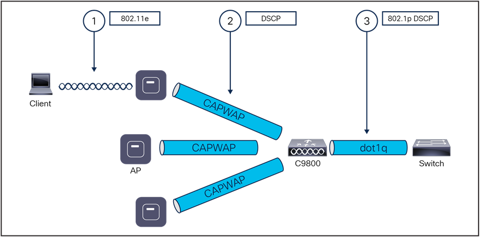
Classification mechanisms in the CAPWAP WLAN network
Multiple classification mechanisms and client capabilities require multiple strategies. These strategies include the following:
● CAPWAP control frames require prioritization, so they are marked with a DSCP classification of CS6 (an IP routing class).
● WMM-enabled clients have the classification of their frames mapped to a corresponding DSCP classification for CAPWAP packets to the WLC. This mapping follows the standard IEEE CoS-to-DSCP mapping, except for the changes necessary for QoS baseline compliance. When the DSCP trust is set at the WLC, this DSCP value is translated at the WLC to a CoS value on 802.1Q frames leaving the WLC interfaces.
● Non-WMM clients have the DSCP of their CAPWAP tunnel set to best effort regardless of the QoS profile for that WLAN.
● CAPWAP data packets from the WLC have a DSCP classification that is determined by the DSCP classification of the wired data packets sent to the WLC. The 802.11e classification used when transmitting frames from the AP to a WMM client is determined by the AP table converting DSCP to WMM classifications.
Catalyst 9800 Series QoS configuration model
The QoS configuration model in the Catalyst 9800 Series is different from the traditional way of configuring QoS. The new model embraces the Cisco IOS XE based Modular QoS CLI (MQC) format. This model gives more flexibility and control over handling wireless traffic of different applications. The figure below shows the MQC format.
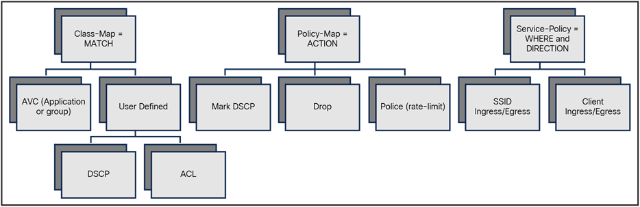
QoS MQC configuration model
As with any other Cisco IOS XE device, QoS features on the Catalyst 9800 are enabled through the MQC. The MQC is a CLI structure that allows you to create traffic policies and attach these policies to targets (class maps, policy maps, etc.).
Catalyst 9800 QoS is based on MQC. In Cisco IOS XE, MQC is used to implement the Differentiated Service model, the end-to-end network QoS architecture defined in RFC 2474 and RFC 2475. This model is common to routing, switching, and wireless platforms running the Cisco IOS XE operating system.
The primary MQC constructs are:
● Class map: Configures the match criteria for a class map based on the specified protocol/DSCP/ACL.
● Policy map: A named object representing a set of policies that are to be applied to a set of traffic classes. Allowed actions that can be taken in classified traffic are drop the traffic, rate-limit the traffic and re-mark the traffic to a different DSCP.
● Service policy: Defined policy maps are applied to the wireless targets through a service policy. Targets can use an SSID, client, or ports.
The following example demonstrates how this works together to define and implement a QoS policy to match some critical traffic and use priority queuing to give it a preferred service. Figure 34 shows the MQC implementation of the policy:
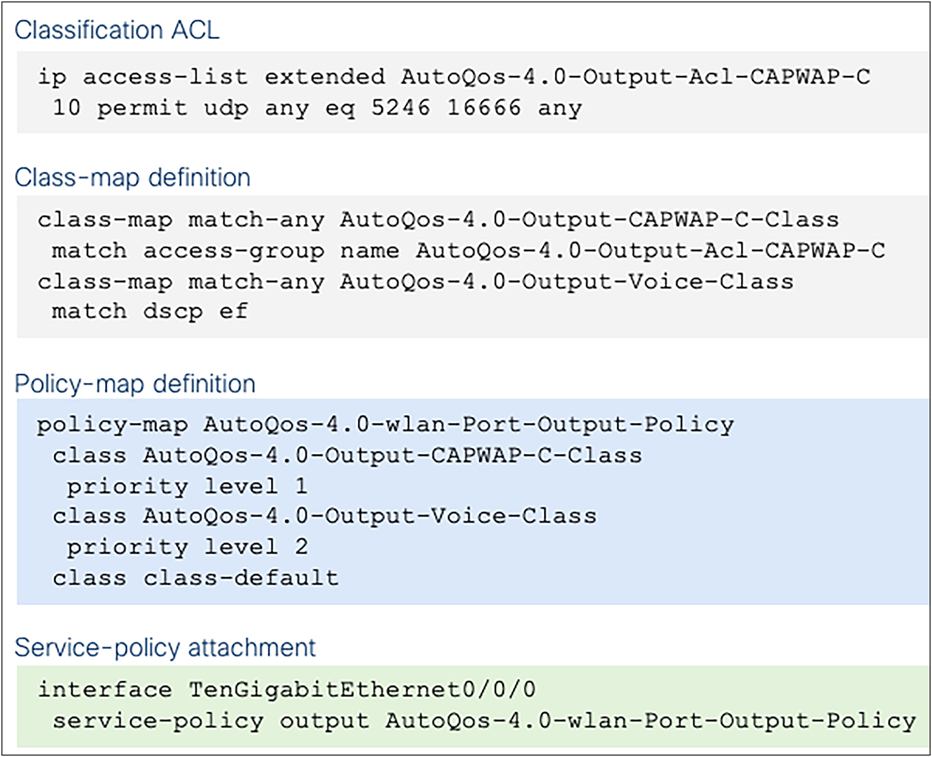
Example of MQC policy
It is a modular approach, as the name Modular QoS CLI implies. First, classify the traffic to consider. Classification can be done by matching on a user-defined condition (specified with an access list or a DSCP value) or by matching on an application using the Network-Based Application Recognition (NBAR) engine. In the example, the user first defines an ACL to match the CAPWAP control traffic (port UDP = 5246 for CAPWAP between AP and WLC, and UDP = 1666 for mobility group tunnels). The next step is to define a class map to match based on the ACL and DSCP = EF for voice traffic. Then the actual policy is defined: assign priority queue 1 for traffic identified as CAPWAP control; for voice traffic, use priority queue 2. The last step is to apply the policy to the target; in this case, it is the uplink port in the output or egress direction.
“DSCP trust” is the QoS model supported by the Catalyst 9800 Series. This means that all QoS processing (queuing and policies) applied to the wireless traffic within the AP and WLC is based on the client DSCP value and not the 802.11 User Priority (UP).
For example, for a centralized switching SSID in the downstream direction (wired to wireless traffic), the AP takes the DSCP value from the received CAPWAP header and uses it for internal QoS processing and mapping (received DSCP > UP > access category). The DSCP value is mapped to the UP value in the frame to the wireless client using the data in the table below according to RFC 8325.
Table 10. DSCP to UP map
| IETF DiffServ service class |
DSCP |
802.11 user priority |
801.11 access category |
| Network control |
CS6, (CS7) |
0 |
AC_BE |
| IP telephony |
EF |
6 |
AC_VO |
| VOICE-ADMIT |
44 |
6 |
AC_VO |
| Signaling |
CS5 |
5 |
AC_VI |
| Multimedia conferencing |
AF4x |
4 |
AV_VI |
| Real-time interactive |
CS4 |
5 |
AC_VI |
| Multimedia streaming |
AF3x |
4 |
AC_VI |
| Broadcast video |
CS3 |
4 |
AC_VI |
| Low-latency data (transactional) |
AF2x |
3 |
AC_BE |
| Operations, Administration, and Maintenance (OAM) |
CS2 |
0 |
AC_BE |
| High-throughput data (bulk data) |
AF1x |
2 |
AC_BK |
| Low-priority data (scavenger) |
CS1 |
1 |
AC_BK |
| Remaining |
Remaining |
0 |
AC_BE |
For DSCP values that don’t map to an entry in Table 10, the Catalyst 9800 Series will use UP = 0, so traffic is sent as best effort.
In the upstream direction we recommend configuring the AP to map the inner DSCP client value to the outer CAPWAP header. This is done using the command in the following table under the AP Join profile:
Table 11. Command for mapping inner DSCP client value to outer CAPWAP header
| Command or action |
Purpose |
| ap profile <name> qos-map trust-dscp-upstream |
Enter the AP Join profile Trust the DSCP and do not use UP<->DSCP conversion |
If not configured, the AP will use the UP value and map it to the DSCP value described in Table 11. Starting with Release 17.4, qos-map trust-dscp-upstream is the default setting so that client DSCP is, by default, maintained from end to end.
A target is an entity to which the policy is applied. Wireless QoS policies for SSID and client are applied in the upstream and/or downstream direction. The flow of traffic from a wired source to a wireless target is known as downstream traffic. The flow of traffic from a wireless source to a wired target is known as upstream traffic.
The following are some of the specific features provided by wireless QoS:
● SSID and client policies on wireless QoS targets.
● Marking and policing (also known as rate limiting) of wireless traffic.
This section describes the various wireless QoS targets available on a device:
● SSID policies
● Client policies
● Ports
● QoS features supported on wireless targets
QoS policies on an SSID can be created in both the ingress and egress directions. If not configured, no SSID policy is applied. The policy is applicable per AP per SSID per radio. In addition, traffic policing (rate limit) and marking policies on the SSID can be configured.
Client policies are applicable in the ingress and egress directions. Configuring policing and marking/re-marking on clients is done through AAA override from the RADIUS server.
Port-based QoS policies can be applied at a physical or logical (port-channel) port, and the Catalyst 9800 Series supports priority queuing only through Auto-QoS configuration.
QoS features supported on wireless targets
The table below describes the various features available on wireless targets.
Table 12. QoS features available on wireless targets
| Target |
Features |
Direction in which policies are applicable |
| SSID |
Set Police Drop |
Upstream and downstream |
| Client |
Set Police Drop |
Upstream and downstream |
For more information on QoS, see the Quality of Service chapter of the Cisco Catalyst 9800 Series Wireless Controller Software Configuration Guide:
The section discusses the handling of broadcast and multicast traffic by a WLC and its impact on design. Figure 35 depicts basic 802.11 broadcast and multicast behavior. In this example, when client 1 sends an 802.11 broadcast frame, it is unicasted to the AP. The AP then sends the frame as a broadcast from both its wireless and wired interfaces. If there are other APs on the same wired VLAN as the broadcasting AP, they also forward the wired broadcast packet out from their wireless interface.
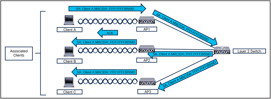
802.11 broadcast and multicast behavior
The WLC CAPWAP split MAC method treats broadcast traffic differently, as shown in Figure 36. In this case, when a broadcast packet is sent by a client, the AP or WLC does not forward it back out the WLAN, and only a subset of all possible broadcast messages are forwarded out a given WLAN's wired interface at the WLC.
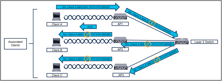
Default WLC broadcast behavior
WLC broadcast and multicast details
Broadcast and multicast traffic often requires special treatment within a WLAN network because of the additional load placed on the WLAN because of this traffic having to be sent at the lowest common data rate. This is done to ensure that all associated wireless devices can receive the broadcast or multicast information.
The default behavior of the WLC is to block broadcast and multicast traffic from being sent out the WLAN to other wireless client devices. The WLC can do this without impacting client operation because most IP clients do not send broadcast and multicast type traffic for any reason other than to obtain network information (DHCP).
Internal DHCP server
The device contains an internal DHCP server. This server is typically used in branch offices that do not have a DHCP server.
The internal server provides DHCP addresses to wireless clients, direct-connect APs, and DHCP requests that are relayed from APs. Only lightweight APs are supported. If you want to use the internal DHCP server, ensure that you configure an SVI for the client VLAN, and set the IP address as the DHCP server IP address.
DHCP option 43 is not supported on the internal server. Therefore, the APs must use an alternative method to locate the IP address of the device’s management interface, such as local subnet broadcast, DNS, or priming.
When clients use the internal DHCP server of the device, IP addresses are not preserved across reboots. As a result, multiple clients can be assigned to the same IP address. To resolve any IP address conflicts, clients must release their existing IP address and request a new one.
General guidelines
The internal DHCP server serves both wireless and wired clients (wired clients include APs).
To serve wireless clients with an internal DHCP server, a unicast DHCP server IP address must be configured for wireless clients. An internal DHCP server IP address must be configured under the server-facing interface, which can be a loopback interface, SVI interface, or Layer 3 physical interface.
To use an internal DHCP server for both wireless and wired client VLAN, an IP address must be configured under the client VLAN SVI interface.
For wireless clients, in the DHCP helper address configuration, the IP address of the internal DHCP server must be different from the address of the wireless client’s VLAN SVI interface.
For wireless clients with internal DHCP server support, the internal DHCP server can be configured using a global configuration command, under the client’s VLAN SVI interface or under the wireless policy profile.
An internal DHCP server pool can also serve clients of other controllers.
External DHCP servers
The operating system is designed to appear as a DHCP relay to the network and as a DHCP server to clients with industry-standard external DHCP servers that support DHCP relay, which means that each controller appears as a DHCP relay agent to the DHCP server and as a DHCP server in the virtual IP address to wireless clients.
Because the controller captures the client IP address that is obtained from a DHCP server, it maintains the same IP address for that client during intra-controller, inter-controller, and inter-subnet client roaming.
DHCP assignments
You can configure DHCP on a per-interface or per-WLAN basis. We recommend that you use the primary DHCP server address that is assigned to a particular interface.
You can assign DHCP servers for individual interfaces. You can configure the management interface, AP manager interface, and dynamic interface for a primary and secondary DHCP server and configure the service-port interface to enable or disable DHCP servers. You can also define a DHCP server on a WLAN (in this case, the server overrides the DHCP server address on the interface assigned to the WLAN).
Security considerations
For enhanced security, we recommend that you ask all clients to obtain their IP addresses from a DHCP server. To enforce this requirement, you can configure all the WLANs with a DHCP Address Assignment Required setting, which disallows client static IP addresses. If DHCP Address Assignment Required is selected, clients must obtain an IP address through DHCP. Any client with a static IP address is not allowed on the network. The controller monitors DHCP traffic because it acts as a DHCP proxy for the clients.
You can create WLANs with DHCP Address Assignment Required disabled. If you do this, clients have the option of using a static IP address or obtaining an IP address from a designated DHCP server. However, note that this might compromise security.
You can create separate WLANs with DHCP Address Assignment Required configured as disabled. This is applicable only if DHCP proxy is enabled for the controller. You must not define the primary or secondary configuration DHCP server; instead, you should disable the DHCP proxy. These WLANs drop all the DHCP requests and force clients to use a static IP address. The WLANs do not support management over wireless connections.
DHCP option 82
DHCP option 82 provides additional security when DHCP is used to allocate network addresses. It enables the controller to act as a DHCP relay agent to prevent DHCP client requests from untrusted sources. You can configure the controller to add option 82 information to DHCP requests from clients before forwarding the requests to the DHCP server.
The AP forwards all the DHCP requests from a client to the controller. The controller adds the DHCP option 82 payload and forwards the request to the DHCP server. The payload can contain the MAC address or the MAC address and SSID of the AP, depending on how you configure this option.
Restrictions for configuring DHCP for WLANs
● If you override the DHCP server in a WLAN, you must ensure that you configure the underlying Cisco IOS configuration to make sure that the DHCP server is reachable.
● WLAN DHCP override works only if DHCP service is enabled on the controller.
● You can configure DHCP service in either of the following ways:
◦ Configuring the DHCP pool on the controller.
◦ Configuring a DHCP relay agent on the SVI. Note that the VLAN of the SVI must be mapped to the WLAN where DHCP override is configured.
The VideoStream feature makes the IP multicast stream delivery reliable over the air by converting the broadcast frame over the air to a unicast frame. Each VideoStream client acknowledges receiving a video IP multicast stream. VideoStream is supported on all Cisco APs.
The following are the recommended guidelines for configuring VideoStream on the controller:
● All Catalyst access points support the reliable multicast feature.
● Ensure that the multicast feature is enabled. As a best practice, Cisco recommends configuring IP multicast on the controller with multicast-multicast mode.
● Check for the IP address on the client device. The device should have an IP address from the respective VLAN.
● Verify that the AP has joined the controllers.
● Ensure that the clients can associate to the configured WLAN at 802.11a/n/ac/ax speed.
For more information on VideoStream, see Configure VideoStream on Catalyst 9800 WLC: https://www.cisco.com/c/en/us/support/docs/wireless/catalyst-9800-series-wireless-controllers/215859-video-stream-on-catalyst-9800-wireless-c.html.
Other broadcast and multicast traffic
As mentioned earlier, the WLC (by default) does not forward broadcasts or multicasts toward the wireless users. If multicast forwarding is explicitly enabled, steps should be taken to minimize the multicast traffic generated on those interfaces that the WLC connects to.
All normal precautions should be taken to limit the multicast address groups explicitly supported by a WLAN. When multicast is enabled, it is global in nature, meaning it is enabled for every WLAN configured regardless of whether multicast is needed by that WLAN or not. The Cisco Unified Wireless Network solution is not able to distinguish between data link layer and network layer multicast traffic, nor is the WLC capable of filtering specific multicast traffic. Therefore, the following additional steps should be considered:
● Disable Cisco Discovery Protocol on interfaces connecting to WLCs.
● Port-filter incoming Cisco Discovery Protocol and Hot Standby Router Protocol traffic on VLANs connecting to the WLCs.
● Keep in mind that multicast is enabled for all WLANs on the WLC, including the guest WLAN; therefore, multicast security, including link layer multicast security, must be considered.
For a Cisco Unified Wireless Network deployment, the primary design considerations are WLC location and AP-to-WLC connectivity. This section will briefly discuss these topics for centralized (local mode) AP deployments and make general recommendations where appropriate. Recommendations and design considerations for FlexConnect AP deployments are not covered in this section and are instead discussed in Chapter 9, “FlexConnect.”
Figure 37 illustrates a distributed WLC deployment. In this model the WLCs are located throughout the campus network, typically on a per-building basis, to manage the APs that are resident in the given building. The WLCs are connected to the campus network by way of the distribution layer switches within each building. In this scenario the CAPWAP tunnels between the AP and the WLC stay within each building.
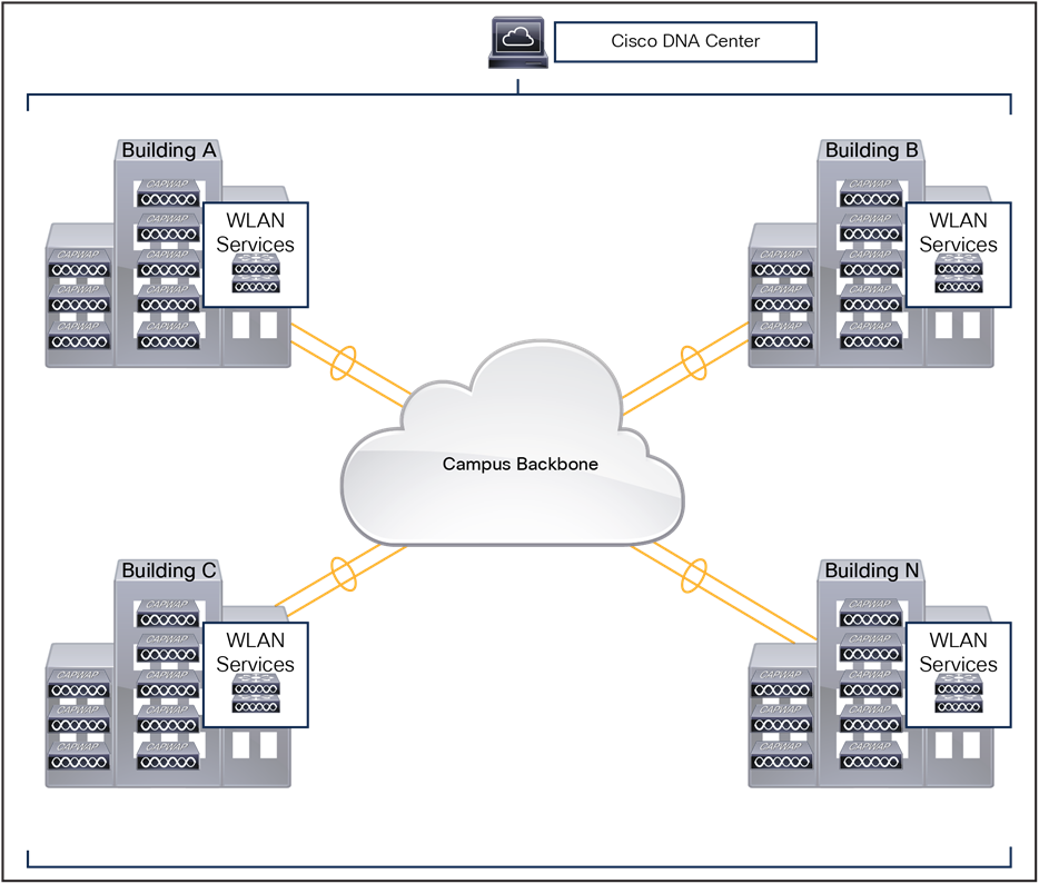
WLCs in a distributed deployment
Figure 38 illustrates a centralized WLC deployment. In this model, WLCs are placed at a centralized location in the campus network. This deployment model requires the CAPWAP tunnels to traverse the campus backbone network. Note in the illustration that the centralized WLCs are not shown in a specific building. The centralized pool of WLCs is connected by way of a dedicated switch block to the campus core, which is typically located in the same building as the data center. The WLCs should not be connected directly to the data center switching block because network and security requirements within data center are generally different from those of the WLC pool.
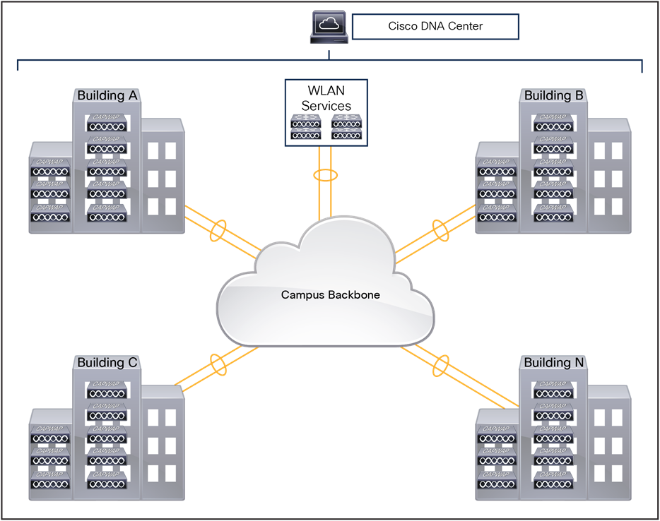
Centralized WLC deployment in a campus
Cisco’s recommendation for WLC placement is dependent on the size and scale of the Cisco Unified Wireless Network deployment. The following section provides reference architectures with recommended WLC placement and redundancy configurations for small, medium, large, and very large campus networks, each based on Cisco’s hierarchical design principles. A reference architecture for a remote branch office deployment using Local mode APs is also provided at the end of this section.
Small campus
Figure 39 shows the recommended WLC placement for a Cisco Unified Wireless Network deployment for a small campus network implementing a distribution layer operating as a collapsed core. The distribution layer provides connectivity to the WLCs, WAN, and internet edge. Depending on the size of the LAN, the WLCs may connect directly to the distribution layer or be connected by means of a dedicated switch block (as shown). The small campus in this example is a single building with multiple access layer switches.
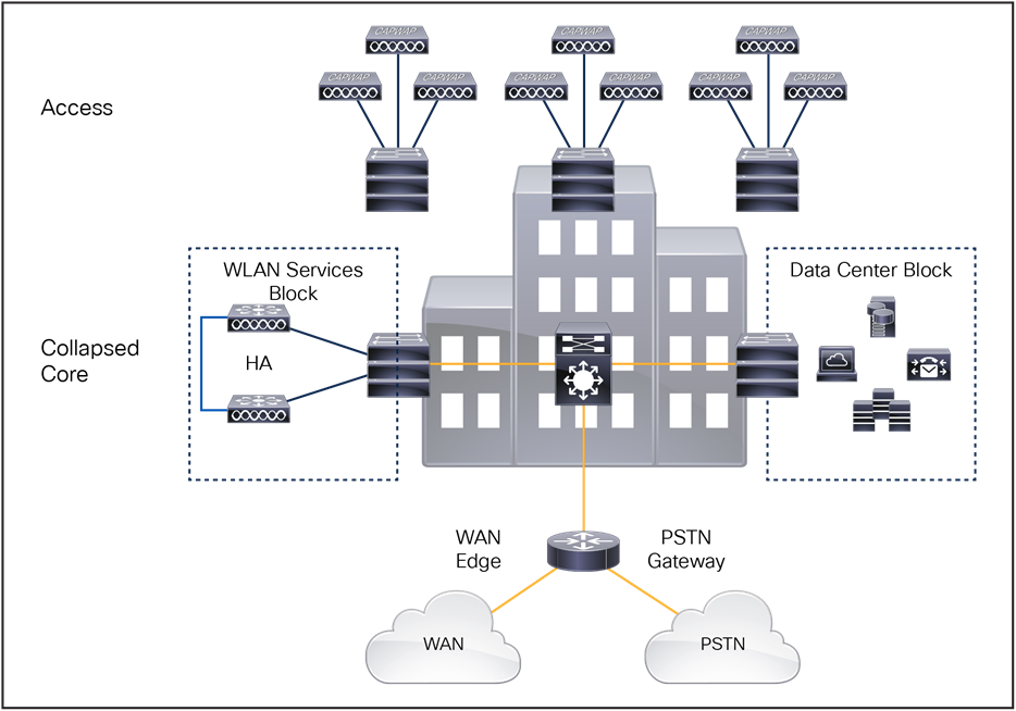
Small campus WLC deployment
Medium-sized campus
Figure 40 shows the recommended WLC placement for a Cisco Unified Wireless Network deployment for a medium-sized campus network implementing a dedicated distribution layer. The benefits of deploying a dedicated distribution layer for larger networks are well documented and understood. The WLCs in this architecture connect directly to the core layer by means of a dedicated switch block. The medium-sized campus in this example is a single building with multiple floors, each with multiple access layer switches.
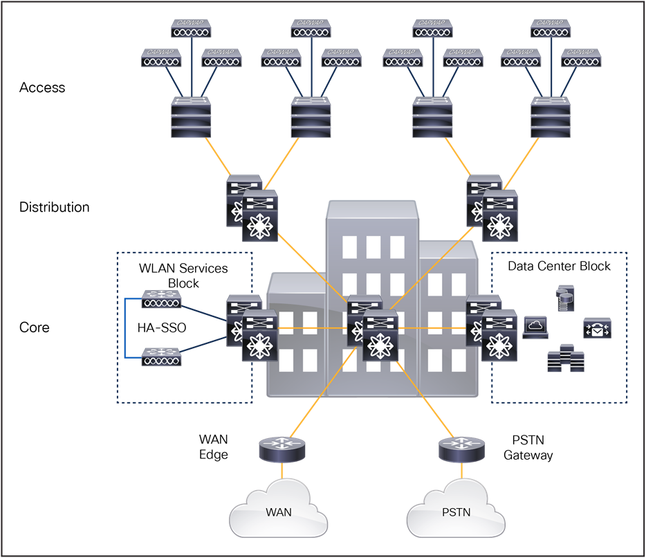
Medium-sized campus deployment
Large campus
Figure 41 shows the recommended WLC placement for a Cisco Unified Wireless Network deployment for a large campus network consisting of multiple buildings connected to a campus core. The WLCs in this architecture are distributed between the buildings, and each pair of WLCs manages the APs within their given building. The WLCs in this architecture connect directly to the distribution layer within each building.
As multiple pairs of WLCs are distributed throughout the campus, each WLC is assigned as a member of the same mobility group to provide seamless mobility to clients as they roam throughout the campus. The WLCs in each building are assigned different wireless management and user VLANs that terminate at the distribution layer within each given building. Mobility tunnels are used to forward roaming users’ traffic between the foreign and anchor WLCs through the campus core.
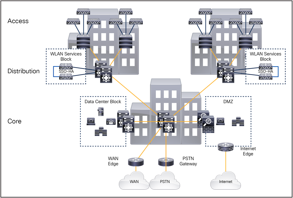
Large campus reference design
Distributing the WLCs among the buildings provides several scaling advantages as the number of wireless clients supported by a Cisco Unified Wireless Network increases. As more devices are added to the wireless network, the number of Layer 2 and Layer 3 table entries that are processed and maintained by the service block switches increases exponentially. This results in a higher CPU load on the service block switches.
Why is this consideration important? The current generation of WLCs can scale to support up to 6000 APs and 64,000 clients. In a pure IPv4 environment, this can result in 128,000 entries being processed and maintained by the service block switches. Because most wireless clients also support a dual stack, the number of entries that are processed and maintained can increase even further.
As a best practice, Cisco recommends distributing the WLCs for large campus deployments supporting 25,000 or more wireless clients. Distributing the WLCs spreads the MAC, ARP, and neighbor discovery processing and table maintenance between the distribution layer switches, reducing CPU load. This architecture also allows for faster convergence during a distribution layer failure, as only a subset of the entries need to be relearned by the affected distribution layer. If the campus deployment supports fewer than 25,000 clients, a centralized WLC architecture can be employed in which the WLCs are connected to the core by means of a dedicated switch block (see the medium-sized campus section above).
Very large campus
Figure 42 shows the recommended WLC placement for a Cisco Unified Wireless Network deployment for a very large campus network supporting hundreds of buildings that connect to a distributed core layer. Each distributed core switch acts as a distribution layer within the campus core. Large buildings in the campus implement their own distribution and access layers, while smaller buildings implement only an access layer.
The WLCs in this architecture are distributed among the core layer switches, where each pair of WLCs manages the APs for groups of buildings. Each wireless services block can support up to 6000 APs, 25,000 clients, and 40 Gbps of throughput. The WLCs in each wireless services block are assigned different wireless management and user VLANs that terminate at the distributed/core layer servicing each group of buildings. The number of required wireless services blocks is determined by the number of wireless devices that need to be supported.
The example campus network shown in Figure 42 implements four separate wireless services blocks, each block supporting groups of buildings placed into a specific zone. This Cisco Unified Wireless Network design comfortably scales to support up to 24,000 APs and 100,000 clients.
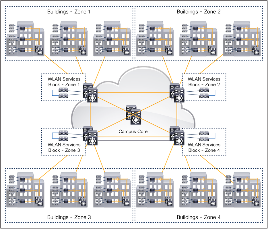
Very large campus reference design
The mobility group design for a very large campus is also an important consideration and is dependent on the wireless coverage provided between the buildings and zones. Ideally the buildings placed into each zone represent a wireless coverage area.
● If continuous wireless coverage is provided within each zone and between zones, a single mobility group can be defined. Each pair of WLCs is configured as members of the same mobility group. Wireless clients will be able to seamlessly roam throughout the campus while maintaining their original network membership.
● If continuous wireless coverage is provided only within each zone, separate mobility groups must be deployed. Each pair of WLCs is configured with a separate mobility group. Wireless clients will be able to maintain their network membership within the zone and be assigned to a new network when they connect to an AP in a separate zone.
● If continuous wireless coverage is provided between some of the zones, the WLCs servicing those zones may be assigned to the same mobility group. Wireless clients will be able to maintain their network membership within those zones and be assigned to a new network when they connect to an AP in a separate zone.
The Cisco Catalyst 9800-CL is the next generation of enterprise-class wireless controllers for cloud, with seamless software updates for distributed branches and midsize campuses to large enterprises and service providers.
The Catalyst 9800-CL controller is feature rich and enterprise ready to power your business-critical operations and transform end-customer experiences:
● High availability and seamless software updates, enabled by hot and cold patching, keep your clients and services always on in planned and unplanned events.
● Secure air, devices, and users with the Catalyst 9800-CL. Wireless infrastructure becomes the strongest first line of defense with Cisco ETA and Software-Defined Access (SD-Access). The controller comes with built-in security: runtime defenses, image signing, and integrity verification.
● Deploy anywhere to enable wireless connectivity everywhere. Whether in a public or private cloud, the Catalyst 9800-CL best meets your organization’s needs.
● Built on a modular operating system, the 9800-CL features open and programmable APIs that enable automation of day-0 to day-N network operations. Model-driven streaming telemetry provides deep insights into the health of your network and clients.
● Cisco User Defined Network, a feature available in Cisco DNA Center, allows IT to give end users control of their very own wireless network partition on a shared network. End users can then remotely and securely deploy their devices on this network. Perfect for university dormitories or extended hospital stays, Cisco User Defined Network grants both device security and control, allowing each user to choose who can connect to their network.
● The Wi-Fi 6 readiness dashboard is a new dashboard in the Assurance menu of Cisco DNA Center. It will look through the inventory of all devices on the network and verify device, software, and client compatibility with the new Wi-Fi 6 standard. After upgrading, advanced wireless analytics will indicate performance and capacity gains as a result of the Wi-Fi 6 deployment. This is an incredible tool that will help your team define where and how the wireless network should be upgraded. It will also give you insights into the access point distribution by protocol (802.11 ac/n/abg), wireless airtime efficiency by protocol, and granular performance metrics.
● With ISSU, network downtime during a software update or upgrade is a thing of the past. ISSU is a complete image upgrade and update while the network is still running. The software image—or patch—is pushed onto the wireless controller while traffic forwarding continues uninterrupted. All AP and client sessions are retained during the upgrade process. With just a click, your network automatically upgrades to the newest software.
Cisco Catalyst 9800-CL for private cloud
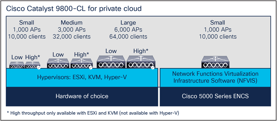
Catalyst 9800-CL for private cloud
Highlights
● Supports VMware ESXi, KVM, Hyper-V, and Cisco NFVIS (on ENCS).
● Supports centralized, Cisco FlexConnect, mesh, and fabric (SD-Access) deployment.
● Multiple scale and throughput* profiles with a single deployment package.
● Small (low/high throughput): Designed for distributed branches and small campuses supporting up to 1000 APs and 10,000 clients.
● Medium (low/high throughput): Designed for medium-sized campuses supporting up to 3000 APs and 32,000 clients.
● Large (low/high throughput): Designed for large enterprises and service providers supporting up to 6000 APs and 64,000 clients.
● One deployment package for all the scale templates. Pick the deployment size and the throughput profile when you instantiate the VM.
● Supports up to 2.1 Gbps of throughput in a centralized wireless deployment (low-throughput profile without Single-Root I/O Virtualization [SR-IOV]).
● With a high (enhanced) throughput profile, up to 5 Gbps can be reached on ESXi and KVM with the right set of network cards and resources (SR-IOV-enabled NIC card).
● An intuitive bootstrap wizard is available during the VM instantiation to boot the wireless controller with recommended parameters.
● Optimize your branch by deploying the 9800-CL as a virtual machine on the Cisco 5000 Series Enterprise Network Compute System (ENCS) running Cisco NFVIS.
*High-throughput profiles are available only with ESXi and KVM hypervisors.
Cisco Catalyst 9800-CL for public cloud
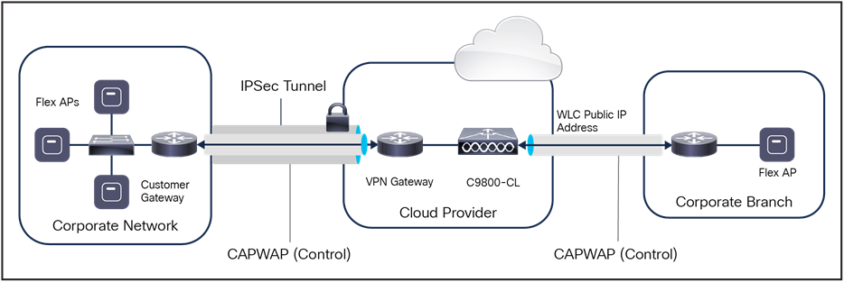
Catalyst 9800-CL in a public cloud
Highlights
● The Cisco Catalyst 9800-CL is available as an Infrastructure-as-a-Service (IaaS) solution on the Amazon Web Services (AWS), Google Cloud Platform (GCP), and Microsoft Azure marketplaces.
● Supported with managed VPN deployment mode until Release 17.7.
● The 9800-CL should be instantiated within a Virtual Private Cloud (VPC).
● A VPN tunnel must be established from the customer site to AWS, GCP, or Azure to enable communication between the Cisco AP and 9800-CL WLC.
● Supported with public IP for AP onboarding from Release 17.8.1.
● Cisco FlexConnect central authentication and local switching.
● Available on AWS GovCloud.
● Supports up to 6000 access points and 64,000 clients.
● Deploy a wireless controller instance in AWS using cloud-formation templates provided by Cisco (recommended) or by manually using the EC2 console.
● Deploy a wireless controller in GCP and Azure using the guided workflow in the marketplace.
Mobility, or roaming, is a WLAN client’s ability to maintain its association seamlessly from one access point to another securely and with as little latency as possible. This section explains how mobility works when controllers are included in a wireless network.
A mobility group is a set of controllers, identified by the same mobility group name that defines the realm of seamless roaming for wireless clients. By creating a mobility group, you can enable multiple WLCs in a network to dynamically share essential client, AP, and RF information as well as forward data traffic when intercontroller or intersubnet roaming occurs. WLCs in the same mobility group can share the context and state of client devices as well as their list of APs so that they do not consider each other’s access points as rogue devices. With this information, the network can support intercontroller WLAN roaming and controller redundancy.
A mobility group forms a mesh of authenticated tunnels between member WLCs, thereby allowing any WLC to directly contact another WLC within the group, as shown in Figure 45.
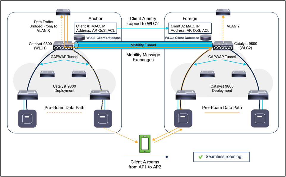
Typical client roam
In the Catalyst 9800, mobility tunnels can be established between WLC peers using either IPv4 or IPv6. The implementation of IPv4 or IPv6 tunnels is driven by the mobility configuration defined for each peer. Table 13 lists the protocols and ports implemented for each mobility tunnel version:
Table 13. Mobility tunnel ports
| Internet Protocol |
IP protocol |
DST port |
Description |
| Version 4 |
17(UDP) |
16666 |
IPv4 mobility tunnel control channel |
| 97(EtherIP) |
|
IPv4 mobility tunnel data channel |
|
| Version 6 |
17(UDP) |
16666 |
IPv6 mobility tunnel control channel |
| 17(UDP) |
16667 |
IPv6 mobility tunnel data channel |
Creating a mobility group is simple and well documented. However, there are a few important considerations to keep in mind:
● Up to 24 WLCs (any model) can be assigned to a single mobility group. A maximum of 144,000 APs are supported in a single mobility group (24 WLCs x 6000 APs = 144,000 APs). An enterprise deployment can consist of more WLCs and APs; however they must be configured as members of a different mobility group.
● The WLCs do not have to be of the same model or type to be a member of a mobility group; however, each member should be running the same software version.
● While mobility groups can function with software differences between members, Cisco strongly recommends that you use a common software version to ensure feature and functional parity across the Cisco Unified Wireless Network deployment.
● If WLCs with SSO are deployed, each WLC SSO pair is considered a single mobility peer.
● A mobility group requires all WLCs in the group to use the same virtual IP address.
● Each WLC must use the same mobility domain name and be defined as a peer in each other’s Static Mobility Members list. The exception to this rule is when guest anchors are deployed. In these cases, Cisco recommends deploying a separate mobility group for the guest anchors.
● For a wireless client to seamlessly roam between mobility group members (WLCs), a given WLAN SSID and security configuration must be consistent across all WLCs in the mobility group.
● As a Cisco best practice, it is recommended that you enable the Multicast Mobility feature on all members of the mobility group. This feature requires a common local group multicast IPv4 address to be defined on each mobility group member.
Mobility groups are used to help facilitate seamless client roaming between APs that are joined to different WLCs. The primary purpose of a mobility group is to create a virtual WLAN domain (across multiple WLCs) to provide a comprehensive view of a wireless coverage area.
The use of mobility groups is beneficial only when a deployment consists of overlapping coverage established by two or more APs that are connected to different WLCs. A mobility group provides no benefit when two APs associated with different WLCs are in different physical locations with no overlapping (contiguous) coverage between them — for example, roaming between a campus and branch or between two or more branches.
The Cisco Unified Wireless Network solution offers network administrators the ability to define static mobility tunnel (auto anchor) relationships between an anchor WLC and other WLCs in the network. This option is used when deploying wireless guest access and BYOD services, among other things.
If the auto anchor feature is used, no more than 71 WLCs can be mapped to a designated anchor WLC. Foreign WLCs do not, by virtue of being connected to the auto anchor, establish mobility relationships with each other. The anchor WLC must have a static mobility group member entry defined for each foreign WLC where a static mobility tunnel is needed. The same is true for each foreign WLC where a static mobility tunnel is being configured; the anchor WLC must be defined as a static mobility group member in the foreign WLC.
A WLC can be a member of only one mobility group for the purpose of supporting dynamic intercontroller client roaming. A WLC that is configured as an auto anchor does not have to be in the same mobility group as the foreign WLCs. It is possible for a WLC to be a member of one mobility group while at the same time acting as an auto anchor for a WLAN originating from foreign WLCs that are members of other mobility groups.
Mobility, or roaming, is the ability of a WLAN client to maintain its association seamlessly from one AP to another securely and with as little latency as possible. This section explains how mobility works when WLCs are included in a Cisco Unified Wireless Network.
When a WLAN client associates and authenticates to an AP, the WLC places an entry for that client in its client database. This entry includes the client MAC and IP addresses, security context and associations, QoS contexts, the WLAN, the SSID and the associated AP. The WLC uses this information to forward frames and manage traffic to and from the wireless client.
Campus deployment – APs in Local mode
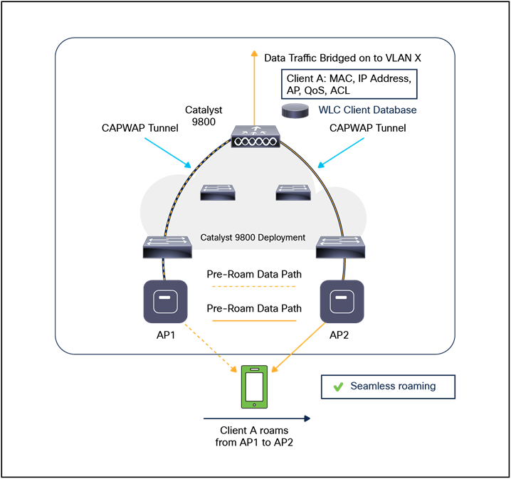
Catalyst 9800 intracontroller roam
The figure below shows a wireless client that roams from one Local mode AP to another when both APs are joined to the same controller.
When the wireless client moves its association from one AP to another, the controller simply updates the client database with the newly associated AP. If necessary, a new security context and associations are established as well.
The process becomes more complicated, however, when a client roams from an AP joined to one controller to an AP joined to a different controller. It also varies based on whether the controllers are operating on the same subnet.
The figure below shows intercontroller Layer 2 roaming, which occurs when the WLAN interfaces of the controllers are on the same IP subnet.
Note: The Catalyst 9800 Series has a new configuration model and introduced the concept of profiles and tags. In a Catalyst 9800 deployment, it is possible for a wireless cclient to roam from one AP to another AP in the same controller but mapped to a different policy. The new configuration model is explained in detail in a section 2.
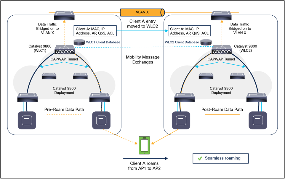
Catalyst 9800 intercontroller Layer 2 roam
When the client associates to an access point joined to a new controller, the new controller exchanges mobility messages with the original controller, and the client database entry is moved to the new controller. A new security context and associations are established if necessary, and the client database entry is updated for the new access point. This process remains transparent to the user.
The figure below shows intercontroller Layer 3 roaming, which occurs when the WLAN interfaces of the controllers are on different IP subnets.
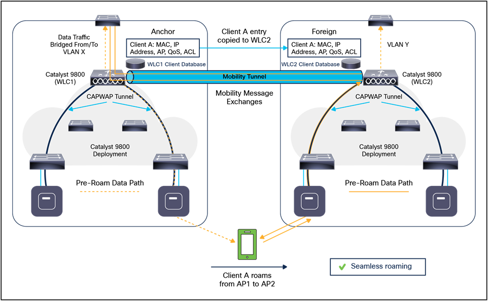
Catalyst 9800 intercontroller Layer 3 roam
Layer 3 roaming is like Layer 2 roaming in that the controllers exchange mobility messages on the client roam. However, instead of moving the client database entry to the new controller, the original controller marks the client with an “anchor” entry in its own client database. The database entry is copied to the new controller client database and marked with a “foreign” entry in the new controller. The roam remains transparent to the wireless client, and the client maintains its original IP address.
To get a complete overview and learn more about Cisco enterprise wireless mobility and roaming in different deployments, please see Cisco Catalyst 9800 Series: A Primer on Enterprise Roaming: https://www.cisco.com/c/en/us/products/collateral/wireless/catalyst-9800-series-wireless-controllers/cat9800-ser-primer-enterprise-wlan-guide.html.
Inter-Release Controller Mobility (IRCM)
Inter-Release Controller Mobility (IRCM) supports seamless mobility and services across different WLAN controllers that run on different software.
For IRCM support between Catalyst 9800 wireless controllers and interoperability with AireOS controllers, see the Cisco Catalyst 9800 Wireless Controller – AireOS IRCM Deployment Guide: https://www.cisco.com/c/en/us/td/docs/wireless/controller/technotes/8-8/b_c9800_wireless_controller-aireos_ircm_dg.html.
Remote office deployment – APs in FlexConnect mode
For a client to roam seamlessly in a remote office deployment with APs in FlexConnect mode, a FlexConnnect site tag is required. The FlexConnect site tag simply groups the APs in a remote site, such as a mobility domain in Local mode that facilitates seamless roaming of clients within the group of APs. Fast roaming is achieved by caching a derivative of the master key from a full EAP authentication so that a simple and secure key exchange can occur when a wireless client roams to a different access point. This feature avoids the need to perform a full RADIUS EAP authentication as the client roams from one access point to another. The FlexConnect APs need to obtain the Cisco Centralized Key Management (CCKM)/Opportunistic Key Caching (OKC)/11r cache information for all the clients that might associate so they can process it quickly instead of sending it back to the controller. If, for example, you have a controller with 300 access points and 100 clients that might associate, sending the CCKM/OKC/11r cache for all 100 clients is not practical. If you create a FlexConnect site tag comprising a limited number of access points (for example, you create a group for four APs in a remote office), the clients roam only among those four APs, and the CCKM/OKC/11r cache is distributed among those four APs only when the clients associate to one of them.
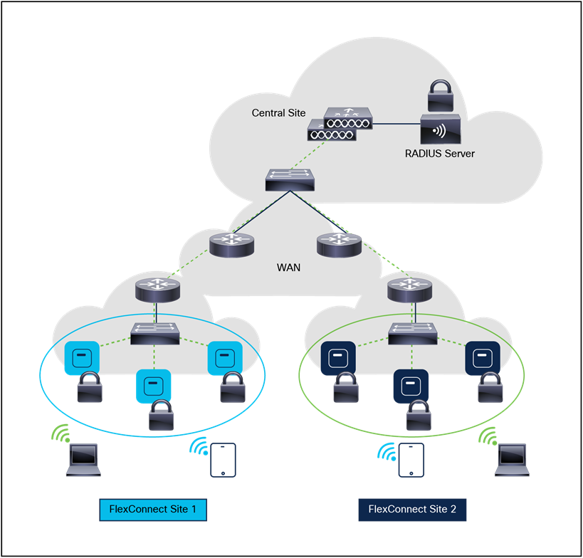
FlexConnect architecture
To accommodate roaming for IPv6 clients across WLCs, the ICMPv6 messages such as Neighbor Solicitations (NS), Neighbor Advertisements (NA), Router Advertisements (RA), and Router Solicitations (RS) must be dealt with to ensure that an IPv6 client remains on the same Layer 3 network. The configuration for IPv6 mobility is the same as for IPv4 mobility and requires no separate software on the client side to achieve seamless roaming. The only required configuration is that the WLCs must be part of the same mobility group.
The following provides some considerations that need to be made when selecting a fast secure roaming method for WLANs:
● It is very important to understand that fast secure roaming methods are developed to accelerate the roaming process when clients move between APs on WPA2 or WPA3 WLANs with security enabled. When no WLAN security is in place, there is no 802.1X/EAP authentication or four-way handshake that can be avoided to accelerate the roam.
● 802.11r is the only fast secure roaming method that supports WPA2-PSK and WPA3-SAE. 802.11r accelerates WPA2-PSK and WPA3-SAE roaming events, avoiding the four-way handshake.
● None of the fast secure roaming methods will work in FlexConnect deployments when WLANs are configured for local authentication. If local authentication is enabled, the clients will perform a full authentication during a roam.
● All the fast secure roaming methods have their advantages and disadvantages, but in the end, you must verify that the wireless client stations support the specific method that you want to implement. You must select the best method that is supported by the wireless clients that connect to the specific WLAN or SSID. For example, in some deployments you might create a WLAN with CCKM for Cisco wireless IP phones (which support WPA2/AES with CCKM, but not 802.11r), and then another WLAN with WPA2/AES or WPA3/AES via 802.11r/FT for wireless clients that support 802.11r (or use OKC/Proactive Key Caching [PKC], if this is what is supported).
● If the 802.1X clients do not support any of the fast secure roaming methods available, those clients will always experience delays when roaming between APs. The 802.1X clients will need to perform a full 802.1X/EAP authentication and four-way handshake during a roaming event. This can cause disruptions to applications and services.
All fast secure roaming methods (except Pairwise Master Key ID [PMKID]/Sticky Key Caching [SKC]) are supported between APs managed by different WLCs (intercontroller roaming), if the WLCs are members of the same mobility group.
FlexConnect is a wireless solution for branch office and remote office deployments. It enables you to configure and control APs in a branch or remote office from the corporate office through a WAN link without the deployment of a controller in each office. The FlexConnect APs can switch client data traffic locally and perform client authentication locally. When they are connected to the controller, they can also send traffic back to the controller.
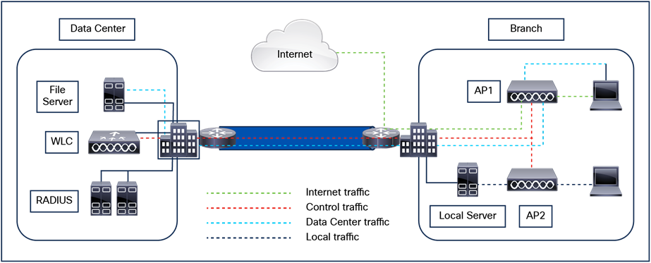
FlexConnect architecture
Note: To view the complete FlexConnect feature matrix, see the Feature Matrix for Cisco Wireless Access Points:
FlexConnect mode is supported on the following platforms:
● Catalyst 9100 access points: Catalyst 9130, 9120, 9115, and 9105 Series
● Wi-Fi/6E access points: Catalyst 9136, 9166, 9164, and 9162 Series
● Wave2/Wave1 access points: Aironet 1800, 2800, 3800, 1540, 1560, 3700, 2700, 1700, and 1570 Series and the 702 and 702W
● Catalyst WLCs: Catalyst 9800-80, 9800-40, 9800-L, 9800-CL (all variants), EWC on Catalyst access points, and EWC on Cisco switches
FlexConnect APs can support the following switching modes concurrently, on a per-WLAN basis.
Locally switched WLANs map wireless user traffic to discrete VLANs via 802.1Q trunking, to either an adjacent router or switch. If so desired, one or more WLANs can be mapped to the same local 802.1Q VLAN.
Branch users who are associated to a locally switched WLAN have their traffic forwarded by the onsite router. Traffic destined offsite (to the central site) is forwarded as standard IP packets by the branch router. All AP control/management-related traffic is sent to the centralized WLC separately via CAPWAP.
Centrally switched WLANs tunnel both the wireless user traffic and all control traffic via CAPWAP to the centralized WLC, where the user traffic is mapped to a dynamic interface/VLAN on the WLC. This is the normal CAPWAP mode of operation.
The traffic of branch users who are associated to a centrally switched WLAN is tunnelled directly to the centralized WLC. If those users need to communicate with computing resources within the branch (where that client is associated), their data is forwarded as standard IP packets back across the WAN link to the branch location. Depending on the WAN link bandwidth, this might not be desirable behavior.
There are two modes of operation for the FlexConnect AP:
Connected mode: The WLC is reachable. In this mode the FlexConnect AP has CAPWAP connectivity with its WLC.
Standalone mode: The WLC is unreachable. The FlexConnect AP has lost or failed to establish CAPWAP connectivity with its WLC, for example, when there is a WAN link outage between a branch and its central site.
A FlexConnect WLAN, depending on its configuration and network connectivity, is classified as being in one of the following defined states.
Authentication-Central/Switching-Central
This state represents a WLAN that uses a centralized authentication method such as 802.1X, PSK, or WebAuth. User traffic is sent to the WLC via CAPWAP. This state is supported only when FlexConnect is in connected mode (Figure 51); 802.1X is used in the example, but other mechanisms are equally applicable.
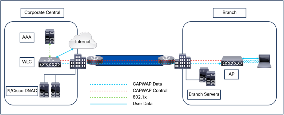
Authentication-Central/Switching-Central WLAN
Authentication-Down/Switching-Down
Centrally switched WLANs (above) no longer beacon or respond to probe requests when the FlexConnect AP is in standalone mode. Existing clients are disassociated.
Authentication-Central/Switching-Local
This state represents a WLAN that uses centralized authentication, but user traffic is switched locally. This state is supported only when the FlexConnect AP is in connected mode (Figure 52); 802.1X is used in the Figure 52 example, but other mechanisms are equally applicable.
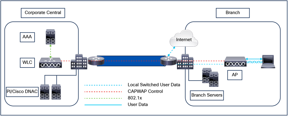
Authentication-Central/Switching-Local WLAN
Authentication-Down/Switching-Local
A WLAN that requires central authentication (as explained above) rejects new users. Existing authenticated users continue to be switched locally until session timeout (if configured). The WLAN continues to beacon and respond to probes until there are no more (existing) users associated to the WLAN. This state occurs when the AP goes into standalone mode (Figure 53).
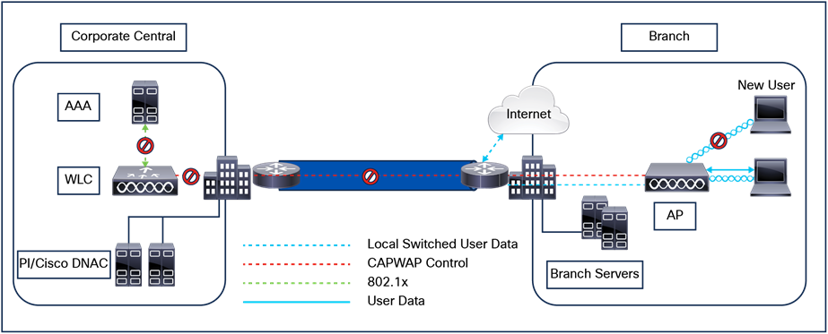
Authentication-Down/Switching-Local
Authentication-Local/Switching-Local
This state represents a WLAN that uses open, 802.1x, or WPA2 PSK security methods. User traffic is switched locally. These are the only security methods supported locally if a FlexConnect AP goes into standalone mode. The WLAN continues to beacon and respond to probes (Figure 54). Existing users remain connected and new user associations are accepted. If the AP is in connected mode, authentication information for these security types is forwarded to the WLC.
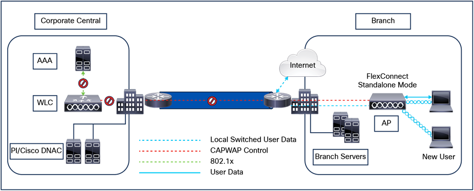
Authentication-Local/Switching-Local
Note: All 802.11 authentication and association processing occurs regardless of which operational mode the AP is in. When in connected mode, the FlexConnect AP forwards all association and authentication information to the WLC. When in standalone mode, the AP cannot notify the WLC of such events, which is why WLANs that make use of central authentication/switching methods are unavailable.
FlexConnect APs offer greater flexibility in how they can be deployed, such as:
● Branch wireless connectivity
● Branch guest access
● Public WLAN hotspot
● Wireless BYOD in branch sites
FlexConnect addresses the wireless connectivity needs in branch locations by permitting wireless user traffic to terminate locally rather than being tunneled across the WAN to a central WLC. With FlexConnect, branch locations can more effectively implement segmentation, access control, and QoS policies on a per-WLAN basis.
The centralized WLC itself, as shown in Figure 55, can perform web authentication for guest access WLANs. The guest user's traffic is segmented (isolated) from other branch office traffic. For more detailed information on guest access, refer to the Wireless Guests section of this guide.
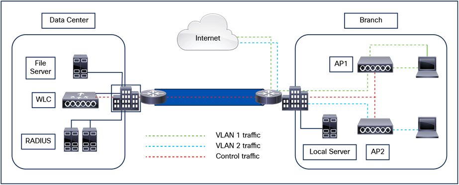
FlexConnect topology
Many public hotspot service providers are beginning to implement multiple SSIDs and WLANs. One reason for this is because an operator might want to offer an open authentication WLAN for web-based access and another WLAN that uses 802.1X/EAP for more secure public access.
The FlexConnect AP, with its ability to map WLANs to separate VLANs, is an alternative to a standalone AP for small venue hotspot deployments where only one, or possibly two, APs are needed. Figure 56 provides an example of hotspot topology using a FlexConnect AP.
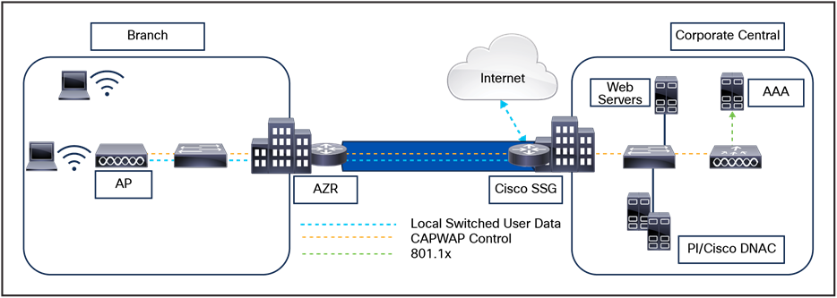
Hotspot access using FlexConnect local switching
The following Bring-Your-Own-Device (BYOD) solutions and features for wireless are available in FlexConnect networks using the latest ISE:
● Device profiling and posture
● Device registration and supplicant provisioning
● Onboarding of personal devices (provisioning iOS or Android devices)
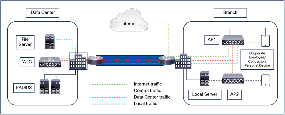
FlexConnect BYOD
The following section covers the various implementation and operational caveats associated with deploying FlexConnect APs.
For the FlexConnect AP to function predictably, keep in mind the following with respect to WAN link characteristics:
Latency: A given WAN link should not impose latencies greater than 100 ms. The AP sends heartbeat messages to the WLC once every 30 seconds. If a heartbeat response is missed, the AP sends five successive heartbeats (one per second) to determine whether connectivity still exists. If connectivity is lost, the FlexConnect AP switches to standalone mode.
Similarly, the AP and WLC exchange echo CAPWAP packets to check the connectivity. If the echo CAPWAP packet response is missed, the AP sends five successive echo CAPWAP packets (every 3 seconds) to determine whether the connectivity still exists. If the connectivity is lost, the FlexConnect AP switches to standalone mode. The AP itself is relatively delay tolerant. However, at the client, timers associated with authentication are sensitive to link delay, and thus a constraint of less than 100 ms is required. Otherwise, the client can time out waiting to authenticate, which can cause other unpredictable behaviors, such as looping.
Bandwidth: WAN links should be at least 128 kbps for deployments when up to eight APs are being deployed at a given location. If more than eight APs are deployed, proportionally more bandwidths should be provisioned for the WAN link.
Path MTU: An MTU no smaller than 500 bytes is required.
When a FlexConnect AP is in connected mode, all client probes, association requests, 802.1X authentication requests, and corresponding response messages are exchanged between the AP and the WLC via the CAPWAP control plane. This is true for open, WPA3, WPA2-802.1X, and WPA2 PSK-based deployments.
Cisco Centralized Key Management (CCKM): CCKM is a protocol developed by Cisco in which the WLC caches the security credentials of CCKM-capable clients and forwards those credentials to other APs within a mobility group. When a client roams and associates with another AP, its credentials are forwarded to that AP, which allows the client to reassociate and authenticate in a two-step process. This eliminates the need for full authentication back to the AAA server. CCKM-capable clients undergo full 802.1X authentication each time they roam from one FlexConnect AP to another.
Opportunistic Key Caching
Opportunistic Key Caching (OKC), also known as Proactive Key Caching (PKC), is basically an enhancement of the WPA2 PMKID caching method. This fast, secure roaming method is not defined in the 802.11 standard.
OKC is used at both the client device and the WLC or AP, depending on the deployment. This technique allows the wireless client and the WLAN infrastructure to cache only one PMK for the lifetime of the client association with this WLAN (derived from the master session key [MSK] after the initial 802.1X/EAP authentication with the authentication server), even when roaming between multiple APs, as they all share the original PMK that is used as the seed on all WPA2 four-way handshakes. The four-way handshake is still required, just as it is in SKC, to generate new encryption keys every time the client reassociates with the APs.
For the APs to share this one original PMK from the client session, they must all be under some sort of administrative control, with a centralized device that caches and distributes the original PMK for all the APs. The WLC (Catalyst 9800) performs this job for all the APs joined and under its control and distributes the PMK to other WLCs in the mobility group.
Fast Transition
802.11r Fast Transition (FT) Roaming, officially named Fast BSS Transition, is an amendment to the 802.11 IEEE standard. BSS Transition refers to the process of disconnecting from one AP and connecting to another without losing connectivity. In Fast BSS Transition, the initial handshake with the new AP occurs before the client roams to the target AP, thus helping to reduce the time it takes to transition to the new AP and making it "Fast.”
Fast Transition Key Hierarchy
FT Key Hierarchy introduces new concepts and multiple layers of PMKs that are cached on the different devices in the WLAN infrastructure. The IEEE 802.11r amendment specifies the three layers of key hierarchy.
The Master Session Key (MSK) is derived on the client supplicant and the authentication server from the 802.1X/EAP initial authentication. (The MSK is transferred from the authentication server to the authenticator after the authentication is successful.) When PSK is used for authentication, the PSK is used as the MSK. The MSK, as in other methods, is used as the seed for the FT Key Hierarchy.
1. PMK-R0: This is the first-level PMK and is derived from the MSK. The key holders for this PMK are the WLC and the client.
2. PMK-R1: This is the second-level PMK and is derived from the PMK-R0. The key holders of PMK-R1 are the APs managed by the WLC and the client.
3. PTK: The Pairwise Transient Key (PTK) is the third and final level key in the hierarchy. The PTK is derived from PMK-R1 and is used to encrypt the data frames. The key holders of PTK are the APs and the client.
A Cisco Catalyst 9800 site tag is required for CCKM/OKC/FT fast roaming to work with FlexConnect access points. Fast roaming is achieved by caching a derivative of the master key from a full EAP authentication so that a simple and secure key exchange can occur when a wireless client roams to a different access point. As discussed previously, this feature avoids the need to perform a full RADIUS EAP authentication as the client roams from one access point to another.
Radio Resource Management (RRM)
While in connected mode, all RRM functionality is fundamentally available. However, because typical FlexConnect deployments consist of a smaller number of APs, RRM functionality might not be operational at a branch location. For example, for TPC to work, there must be a minimum of four FlexConnect APs in proximity to each other. Without TPC, other features such as coverage hole protection will be unavailable.
FlexConnect deployments typically consist of only a handful of APs at a given location. Cisco maintains strict guidelines regarding the number and placement of APs to achieve the highest level of location accuracy. As such, although it is possible to obtain location information from FlexConnect deployments, the level of accuracy may vary greatly across remote location deployments.
For WLANs that are centrally switched, the FlexConnect AP handles QoS in the same way that standard APs do. Locally switched WLANs implement QoS differently.
For locally switched WLANs with WMM traffic, the AP marks the 802.1p value within the 802.1q VLAN tag for upstream traffic. This happens only for tagged VLANs, not the native VLAN.
For downstream traffic, FlexConnect uses the incoming 802.1p tag from the locally switched Ethernet to queue and mark the WMM values associated with frames destined to a given user across the RF link.
The WLAN QoS profile is applied both for upstream and downstream packets. For downstream, if an 802.1p value that is higher than the default WLAN value is received, the default WLAN value is used. For upstream, if the client sends a WMM value that is higher than the default WLAN value, the default WLAN value is used. For non-WMM traffic, there is no CoS marking on the client frames from the AP.
Note: Cisco strongly recommends that appropriate queuing and policing mechanisms be implemented across the WAN to ensure proper handling of traffic based on its DSCP setting. An appropriate priority queue should be reserved for CAPWAP control traffic to ensure that a FlexConnect AP does not inadvertently cycle between connected and standalone modes because of congestion.
The FlexConnect solution enables you to:
● Centralize control and management traffic.
● Distribute the client data traffic at each branch office.
● Ensure that traffic flow is going to its destination in the most efficient manner.
Advantages of centralizing AP control traffic
The advantages of centralizing AP control traffic are:
● Single-pane-of-glass monitoring and troubleshooting.
● Ease of management.
● Secured and seamless mobile access to data center resources.
● Reduction in branch footprint.
● Increase in operational savings.
Advantages of distributing client data traffic
The advantages of distributing client data traffic are:
● No operational downtime (survivability) against complete WAN link failures or controller unavailability.
● Mobility resiliency within the branch during WAN link failures.
● Increase in branch scalability; can scale up to 100 APs (300 APs starting from Cisco IOS XE version 17.8.1).
The Cisco FlexConnect solution also supports central client data traffic, but it should be limited to guest data traffic only. Tables 14 and 15 outline the restrictions on WLAN security types only for non-guest clients whose data traffic is also switched centrally at the data center. Table 14. Layer 2 security.
Table 14. Security Types
| Security |
Type |
Results |
| WPA2 |
802.1x |
Allowed |
| PSK |
Allowed |
|
| Easy Psk |
Allowed |
|
| CCKM |
Allowed |
|
| 802.1x-SHA256 |
Allowed |
|
| PSK-SHA256 |
Allowed |
|
| FT+PSK |
Allowed |
|
| FT+802.1x |
Allowed |
|
| WPA3 |
802.1XSHA256 |
Allowed |
| SAE |
Allowed |
|
| FT+SAE |
Allowed |
|
| OWE |
OWE and Transition |
Allowed |
| MPSK |
Multiple PSK |
Allowed |
| Web Authentication |
WebAuth |
Allowed |
| AuthByPass |
Allowed |
|
| Consent |
Allowed |
|
| WebConsent |
Allowed |
|
| Multi-Auth |
Layer2+Layer3 |
Allowed |
| MAC Filtering |
|
Allowed |
FlexConnect APs are deployed at the branch site and managed from the data center over a WAN link. We highly recommend that the minimum bandwidth restriction remains 24 kbps per AP, with the round-trip latency no greater than 300 ms.
The MTU must be at least 500 bytes.
The primary design requirements are:
● Branch size that can scale up to 100 APs (300 APs starting from Cisco IOS XE version 17.8.1).
● Central management and troubleshooting.
● No operational downtime.
● Client-based traffic segmentation.
● Seamless and secured wireless connectivity to corporate resources.
● Support for guests.
Because all the FlexConnect APs at each branch site are part of a single site, site tags ease the organization of each branch site.
Note: Site tags are analogous to FlexConnect groups in the AireOS-based WLCs.
The Flex profile in the site tag is designed primarily to solve the following challenges:
● How can wireless clients perform 802.1X authentication and access data center services if the controller fails?.
● How can wireless clients perform 802.1X authentication if the WAN link between branch and data center fails?.
● Is there any impact on branch mobility during WAN failures?.
● Does the FlexConnect solution provide no operational branch downtime?.
You can configure the controller to allow a FlexConnect AP, in standalone mode, to perform full 802.1X authentication to a backup RADIUS server.
To increase the resiliency of the branch, administrators can configure a primary backup RADIUS server or both primary and secondary backup RADIUS servers. These servers are used only when the FlexConnect AP is not connected to the controller.
A default Flex profile option has been added on the controller. In retail deployments where the number of APs is huge and some configurations could be similar, it is a tedious process to create a large number of Flex profiles for provisioning the APs. The solution considered here is to have a default Flex profile like that of the default site tag. When an AP in FlexConnect mode that is not part of any administrator-configured Flex profile joins the controller, it becomes part of the default Flex profile and gets the configuration from this profile.
When the controller boots up, the default Flex profile will be available. This profile cannot be deleted or added manually. The Flex profile has a default configuration for a few parameters upon creation and has no maximum limit on the number of APs that can be part of it. Any change in configuration gets propagated to all the APs that are part of this site. The configuration of the site is retained across resets.
When an AP is mapped to the customized Flex profile, the default Flex profile configuration gets deleted, and the new configuration gets pushed to the AP.
The following features are not supported in default Flex profile:
● Efficient image upgrade
● PMK cache distribution
● Fast roaming
The following features are supported:
● VLAN support (native VLAN, WLAN-VLAN mapping)
● VLAN ACL mapping
● WebAuth, web policy, local split mapping
● Local authentication users
● RADIUS authentication
● Central DHCP or NAT-PAT
● Flex Application Visibility and Control (AVC)
● VLAN name ID mapping
● Multicast override
Figure 58 illustrates clients continuing to perform 802.1X authentication even after the FlexConnect branch APs lose connectivity with the controller. If the RADIUS/AAA server is reachable from the branch site, wireless clients will continue to authenticate and access wireless services. In other words, if the RADIUS/AAA server is located inside the branch, clients will authenticate and access wireless services even during a WAN outage.
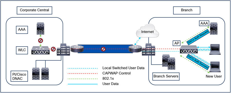
Local AP authentication
● Configure a local backup RADIUS server to increase the resiliency of the branch, taking into consideration failures at the WAN, WLC failures, and failures at the RADIUS server.
● This feature is also used for remote offices where the WAN latency to the central site is high.
● Administrators can configure a primary backup RADIUS server or both primary and secondary backup RADIUS servers. A FlexConnect AP in standalone mode can be configured to perform full 802.1X authentication to a backup RADIUS server.
● These servers are used when the FlexConnect AP is not connected to the controller or when the WLAN is configured for local authentication.
● If the RADIUS/AAA server is located inside the branch, clients will be able to authenticate and access wireless services even during a WAN outage.
Note: When configuring a local backup RADIUS server, note the following limitation: When a local backup RADIUS server is used in the branch, the IP addresses of all the APs acting as authenticators must be added on the RADIUS server.
You can configure the controller to allow a FlexConnect AP in standalone or connected mode to perform LEAP/PEAP/EAP-Fast (supported only in Wave 1 APs). The controller sends the static list of usernames and passwords to each FlexConnect AP of that FlexConnect site when it joins the controller. Each AP in the site authenticates its own associated clients.
This feature is ideal for customers who are migrating from a standalone AP network to a lightweight FlexConnect AP network and are not interested in maintaining a large user database or adding another hardware device to replace the RADIUS server functionality available in the standalone AP.
Support for PEAP and EAP-TLS authentication
A FlexConnect AP can be configured as a RADIUS server for LEAP and EAP-FAST client authentication. In standalone mode and when the local authentication feature is enabled on the WLANs, the FlexConnect AP will do 802.1X authentication on the AP itself using the local RADIUS server. This feature is supported only in Wave 1 access points.
In the current FlexConnect architecture, there is a strict mapping of WLAN to VLAN, and thus a client getting associated to a particular WLAN on a FlexConnect AP must abide by the VLAN that is mapped to it. This method has limitations because it requires clients associated with different SSIDs to inherit different VLAN-based policies.
AAA override of the VLAN on an individual WLAN configured for local switching is supported. To have a dynamic VLAN assignment, APs would have the interfaces for the VLAN precreated based on a configuration using a Flex profile.
● AAA VLAN override is supported in WLANs configured for local switching in central and local authentication mode.
● AAA override should be enabled on a policy configured with local switching.
● The FlexConnect AP should have VLAN precreated from the WLC for dynamic VLAN assignment.
● If VLANs returned by AAA override are not present on AP clients, they will get an IP from the default VLAN interface of the AP.
FlexConnect VLAN-based central switching
Traffic from FlexConnect APs can be switched centrally or locally depending on the presence of a VLAN on a FlexConnect AP.
AAA override of VLAN (dynamic VLAN assignment) for locally switched WLANs puts wireless clients on the VLAN provided by the AAA server. If the VLAN provided by the AAA server is not present at the AP, the client is put on a VLAN mapped in the policy and traffic switches locally on that VLAN.
FlexConnect VLAN central switch summary
Traffic flow on WLANs configured for local switching when FlexConnect APs are in connected mode is as follows:
● If the VLAN is returned as one of the AAA attributes and that VLAN is not present in the FlexConnect AP database, traffic will switch centrally, and the client is assigned this VLAN/Interface returned from the AAA server, provided that the VLAN exists on the WLC. If that VLAN is also not present on the WLC, the client will be assigned a VLAN/interface mapped to the policy.
● If the VLAN is returned as one of the AAA attributes and that VLAN is present in the FlexConnect AP database, traffic will switch locally.
● If the VLAN is not returned from the AAA server, the client is assigned a policy-mapped VLAN on that FlexConnect AP and traffic is switched locally.
Traffic flow on WLANs configured for local switching when FlexConnect APs are in standalone mode is as follows:
● If the VLAN returned by the AAA server is not present in the FlexConnect AP database, the client will be put on a default VLAN (that is, a policy-mapped VLAN on a FlexConnect AP). When the AP connects back, this client is deauthenticated and will switch traffic centrally.
● If the VLAN returned by the AAA server is present in the FlexConnect AP database, the client is placed into a returned VLAN, and traffic will switch locally.
● If the VLAN is not returned from the AAA server, the client is assigned a policy-mapped VLAN on that FlexConnect AP and traffic will switch locally.
The VLAN name override feature is useful in deployments that have a single central RADIUS server authenticating multiple branches. With hundreds of different branches, it becomes very difficult to standardize VLAN IDs across all sites, and requires a configuration that provides a unique VLAN name mapped locally to a VLAN ID that can be different across different branch locations.
This design involving different VLAN IDs across different sites is also useful from the sizing and scaling perspective to limit the number of clients per Layer 2 broadcast domain.
FlexConnect VLAN name override summary
● The VLAN name override feature supports both central and local authentication with local switching WLANs.
● If the AAA server returns multiple VLAN attributes, preference is given to the VLAN name attribute.
● When Aire-Interface-Name and Tunnel-Private-Group-ID are both returned, the Tunnel-Private-Group-ID attribute is given preference.
● If the AAA server returns an unknown VLAN name attribute, the client defaults to the policy VLAN ID mapping present on the AP.
● This feature is also supported in standalone mode.
With the introduction of ACLs on FlexConnect, there is a mechanism to cater to the need of access control at the FlexConnect AP for the protection and integrity of locally switched data traffic from the AP. FlexConnect ACLs are created on the WLC and should then be configured with the VLAN present on the FlexConnect AP or Flex profile using VLAN-ACL mapping, which will be for AAA override VLANs. These are then pushed to the AP.
● Create a FlexConnect ACL on the controller.
● The ACL can be applied on a VLAN present in Flex profile.
● While applying ACL on a VLAN, select the direction to be applied: ingress, egress, or both ingress and egress.
● A maximum of 512 FlexConnect ACLs can be configured on a WLC.
● Each individual ACL can be configured with 64 rules.
● A maximum of 32 ACLs can be mapped per FlexConnect profile or per FlexConnect AP.
● At any given time, there is a maximum of 16 VLANs and 32 ACLs on the FlexConnect AP.
FlexConnect ACLs are supported on the VLAN. Also, AAA override of VLANs is supported. If a client gets an AAA override of VLAN, it is placed on the overridden VLAN and the ACL on the VLAN applies to the client.
Split tunneling introduces a mechanism by which the traffic sent by the client will be classified, based on packet content, using the FlexConnect ACL. Matching packets are switched locally from the FlexConnect AP, and the rest of the packets are centrally switched over CAPWAP.
The split tunneling functionality is an added advantage for OEAP setup where clients on a corporate SSID can talk to devices on a local network (printers, a wired machine on a remote LAN port, or wireless devices on a personal SSID) directly without consuming WAN bandwidth by sending packets over CAPWAP.
A FlexConnect ACL can be created with rules to permit all the devices present at the local site or network. When packets from a wireless client on the corporate SSID match the rules in the FlexConnect ACL configured on OEAP, that traffic is switched locally and the rest of the traffic (that is, implicit deny traffic) will switch centrally over CAPWAP.
The split tunneling feature assumes that the subnet or VLAN associated with a client in the central site is not present in the local site (that is, traffic for clients that receive an IP address from the subnet present on the central site will not be able to switch locally).
Split tunneling is designed to switch traffic locally for subnets that belong to the local site to avoid WAN bandwidth consumption. Traffic that matches the FlexConnect ACL rules are switched locally, and NAT operation is performed, changing the client’s source IP address to the FlexConnect AP interface IP address that is routable at the local site or network.
● Split tunneling functionality is supported on WLANs configured for central switching advertised by FlexConnect APs only.
● The DHCP required should be enabled on WLANs configured for split tunneling.
● The split tunneling configuration is applied per WLAN configured for central switching or for all the FlexConnect APs in a Flex profile.
Split tunneling limitations
● FlexConnect ACL rules should not be configured with permit/deny statements with the same subnet as source and destination.
● Traffic on a centrally switched WLAN configured for split tunneling can be switched locally only when a wireless client initiates traffic for a host present on the local site. If traffic is initiated by clients or a host on a local site for wireless clients on these configured WLANs, the traffic will not be able to reach the destination.
● Split tunneling is not supported for multicast or broadcast traffic. Multicast or broadcast traffic will switch centrally even if it matches the FlexConnect ACL.
● Split tunneling is not supported in a foreign anchor roaming scenario.
FlexConnect fault tolerance allows wireless access and services to branch clients when the FlexConnect branch APs:
● Lose connectivity with the primary controller
● Are switching to the secondary controller
● Are re-establishing connection to the primary controller
FlexConnect fault tolerance, along with the local EAP, provides zero branch downtime during a network outage. This feature is enabled by default and cannot be disabled. It requires no configuration on the controller or AP. However, to ensure that fault tolerance works smoothly and is applicable, these criteria should be maintained:
● WLAN ordering and configurations must be identical across the primary and backup controllers.
● VLAN mapping must be identical across the primary and backup controllers.
● The mobility domain name must be identical across the primary and backup controllers.
● Use supported FlexConnect controllers as both the primary and backup controllers.
● FlexConnect will not disconnect clients when the AP is connecting back to the same controller, provided there is no change in configuration on the controller.
● FlexConnect will not disconnect clients when connecting to the backup controller, provided there is no change in configuration and the backup controller is identical to the primary controller.
● FlexConnect will not reset its radios when connecting back to the primary controller, provided there is no change in configuration on the controller.
● Fault tolerance is supported only for FlexConnect with central or local authentication with local switching.
● Centrally authenticated clients require full reauthentication if the client session timer expires before the FlexConnect AP switches from standalone to connected mode.
● The primary and backup controllers must be in the same mobility domain.
Peer-to-Peer (P2P) blocking is supported for clients associated on a local switching WLAN. Per WLAN, peer-to-peer configuration is pushed by the controller to the FlexConnect AP. P2P blocking can be configured on a WLAN with any of these three actions:
● Disabled: Disables P2P blocking and bridged traffic locally, within the controller, for clients in the same subnet. This is the default value.
● Drop: Causes the controller to discard packets for clients in the same subnet.
● Forward-upstream: Forwards a packet on the upstream VLAN. The devices above the controller decide what action to take regarding the packet.
● P2P blocking is configured per WLAN.
● Per WLAN, the P2P blocking configuration is pushed by the WLC to FlexConnect APs.
● A P2P blocking action configured as drop or forward-upstream on a WLAN is treated as P2P blocking enabled on the FlexConnect AP.
● A P2P blocking configuration cannot be applied only to a particular FlexConnect AP or subset of APs. It is applied to all FlexConnect APs that broadcast the SSID.
● The unified solution for central switching clients supports P2P forward-upstream. However, this is not supported in FlexConnect. This is treated as P2P drop, and client packets are dropped instead of being forwarded to the next network node.
● The unified solution for central switching clients supports P2P blocking for clients associated to different APs. However, this solution targets only clients connected to the same AP. FlexConnect ACLs can be used as a workaround for this limitation.
FlexConnect efficient AP image upgrade
The pre-image download feature reduces the duration of downtime to a certain extent, but all the FlexConnect APs still have to predownload the respective AP images over the WAN link with higher latency.
Efficient AP image upgrade will reduce the downtime for each FlexConnect AP. The basic idea is that only one AP of each AP model will download the image from the controller and will act as primary/server, and the rest of the APs of the same model will work as subordinate/client and will predownload the AP image from the primary.
The distribution of the AP image from the server to the client will be on a local network and will not experience the latency of the WAN link. As a result, the process will be faster.
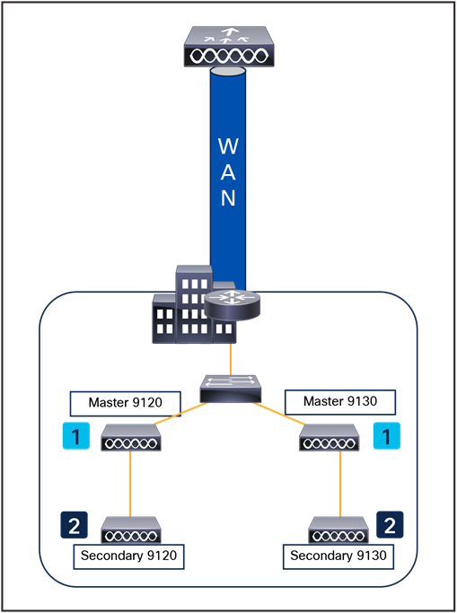
Efficient image upgrade
Efficient AP image upgrade summary
● Primary and subordinate APs are selected for each AP model per FlexConnect profile.
● The primary AP downloads the image from the WLC.
● The subordinate APs download the image from the primary AP.
● This feature reduces downtime and saves WAN bandwidth.
VideoStream for FlexConnect local switching
The VideoStream for local switching feature enables the wireless architecture to deploy multicast video streaming across branches, as is currently possible for enterprise deployments.
This feature recompenses the drawbacks that degrade video delivery as the video streams and clients scale in a branch network. VideoStream makes video multicast to wireless clients more reliable and facilitates better usage of wireless bandwidth in the branch.
Application Visibility and Control (AVC)
AVC provides application-aware control on a wireless network and enhances manageability and productivity. AVC is already supported on Cisco Aggregation Services Router (ASR) and Integrated Services Router Generation 2 (ISR G2) and WLC platforms. Having AVC embedded within the FlexConnect AP extends this support, as it is an end-to-end solution. This gives complete visibility into applications in the network and allows the administrator to take action on the application.
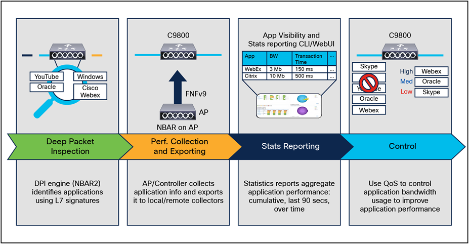
Application Visibility and Control
● An NBAR2 engine runs on the FlexConnect AP.
● Classification of applications happens at the access point using the Deep Packet Inspection (DPI) engine (NBAR2) to identify applications using Layer 7 signatures.
● The AP collects application information and exports it to the controller every 90 seconds.
● Real-time applications are monitored on the controller user interface.
● Actions such as drop, mark, or rate-limit are possible on any classified application on the FlexConnect AP.
● Although it is possible for any WLC to support FlexConnect APs, depending on the number of branch locations and subsequently the total number of APs being deployed, it makes sense (from an administrative standpoint) to consider using one or more dedicated WLC(s) to support a FlexConnect deployment.
● FlexConnect APs typically do not share the same policies as APs within a main campus; each branch location is essentially an RF and mobility domain unto itself. Even though a single WLC cannot be partitioned into multiple logical RF and mobility domains, a dedicated WLC allows branch-specific configuration and policies to be logically separate from the campus.
● If deployed, a dedicated FlexConnect WLC should be configured with a different mobility and RF network name than that of the main campus. All FlexConnect APs joined to the dedicated WLC become members of that RF and mobility domain.
● From an auto-RF standpoint, assuming that there are enough FlexConnect APs deployed within a given branch, the WLC attempts to auto-manage the RF coverage associated with each branch.
● There is no advantage (or disadvantage) in having the FlexConnect APs consolidated into their own mobility domain. This is because client traffic is switched locally. Ethernet over IP (EoIP) mobility tunnels are not invoked between WLCs (of the same mobility domain) where client roaming with FlexConnect APs is involved.
● If a dedicated WLC is going to be used for a FlexConnect deployment, a backup WLC should also be deployed to ensure network availability. As with standard AP deployments, the WLC priority should be set on the FlexConnect APs to force association with the designated WLCs.
● Certain architectural requirements need to be considered when deploying a distributed branch office in terms of the minimum WAN bandwidth, maximum RTT, minimum MTU, and fragmentation.
● You can deploy a FlexConnect AP with either a static IP address or a DHCP address. A DHCP server must be available locally and must be able to provide the IP address for the AP during bootup.
● FlexConnect supports up to four fragmented packets or a minimum 500-byte Maximum Transmission Unit (MTU) WAN link.
● Round-trip latency must not exceed 100 ms between the AP and the controller. If 100 ms round-trip latency cannot be achieved, configure the AP to perform local authentication.
● FlexConnect includes a robust fault tolerance methodology. When the AP and the controller have the same configuration, the connections (rejoin or standby) between the clients and the FlexConnect APs are maintained intact and the clients experience seamless connectivity.
● The primary and secondary controllers for a FlexConnect AP must have the same configuration. Otherwise, the AP might lose its configuration, and certain features (such as WLAN overrides, VLANs, static channel number, and so on) may not operate as expected. In addition, make sure to duplicate the SSID of the FlexConnect AP and its index number on both controllers.
● Client connections are restored only for locally switched clients that are in the RUN state when the AP moves from standalone mode to connected mode. After the AP moves from standalone mode to connected mode, the AP radio is also reset.
● Session timeout and reauthentication are performed when the AP establishes a connection to the controller.
● If a session timer expires, the client username, current/support rate, and listen interval values are reset to the default values. When the client connection is reestablished, the controller does not restore the client’s original attributes.
● Multiple FlexConnect site tags and profiles can be defined in a single location. There is no deployment restriction on the number of FlexConnect APs per location.
● In FlexConnect mode, the AP can receive multicast packets only in unicast form.
● FlexConnect APs support a one-to-one NAT configuration and a PAT for all features except true multicast. Multicast is supported across NAT boundaries when configured using the unicast option. FlexConnect APs also support a many-to-one NAT/PAT boundary, except when you want true multicast to operate for all centrally switched WLANs.
● Although NAT and PAT are supported for FlexConnect APs, they are not supported on the corresponding controller. Cisco does not support configurations in which the controller is behind a NAT/PAT boundary.
● FlexConnect APs do not support client load balancing.
● FlexConnect supports IPv6 clients by bridging the traffic to a local VLAN, like IPv4 operation.
● FlexConnect does not support IPv6 ACLs, neighbor discovery caching, or DHCPv6 snooping of IPv6 NDP packets.
● FlexConnect APs with locally switched WLANs cannot perform IP Source Guard and prevent ARP spoofing. For centrally switched WLANs, the WLC performs IP Source Guard and ARP spoofing. To prevent ARP spoofing attacks in FlexConnect APs with local switching, Cisco recommends you use ARP inspection.
If the network supports packet multicasting, the multicast method that the controller uses can be configured. The controller performs multicast routing in two modes:
● Unicast mode: The controller unicasts every multicast packet to every AP associated to the controller. This mode is inefficient and generates a lot of extra traffic in the device and the network but is required on networks that do not support multicast routing (needed if the APs are on different subnets than the device's wireless management interface).
● Multicast mode: The controller sends multicast packets to a CAPWAP multicast group. This method reduces the overhead on the controller processor and shifts the work of packet replication to the network, which is much more efficient than the unicast method.
FlexConnect mode has two submodes: local switching and central switching. In local switching mode, the data traffic is switched at the AP level and the controller does not see any multicast traffic. In central switching mode, the multicast traffic reaches the controller. However, Internet Group Management Protocol (IGMP) snooping takes place at the AP.
When the multicast mode is enabled and the controller receives a multicast packet from the wired LAN, the controller encapsulates the packet using CAPWAP and forwards the packet to the CAPWAP multicast group address. The controller always uses the management VLAN for sending multicast packets. APs in the multicast group receive the packet and forward it to all the BSSIDs mapped to the VLAN on which clients receive multicast traffic.
The controller supports all the capabilities of IGMPv1, including Multicast Listener Discovery (MLD) v1 snooping, but the IGMPv2 and IGMPv3 capabilities are limited. This feature keeps track of and delivers IPv6 multicast flows to the clients that request them. To support IPv6 multicast, global multicast mode should be enabled.
IGMP snooping was introduced to better direct multicast packets. When this feature is enabled, the controller performing the snooping gathers IGMP reports from the clients, processes them, creates unique Multicast Group IDs (MGIDs) based on the Layer 3 multicast address and the VLAN number, and sends the IGMP reports to the IGMP querier. The controller then updates the AP MGID table on the corresponding AP with the client MAC address. When the controller receives multicast traffic for a particular multicast group, it forwards it to all the access points, but only those access points that have active clients listening or subscribed to that multicast group send multicast traffic on that WLAN. IP packets are forwarded with an MGID that is unique for an ingress VLAN and the destination multicast group. Layer 2 multicast packets are forwarded with an MGID that is unique for the ingress VLAN.
MGID is a 14-bit value filled in the 16-bit reserved field of wireless information in the CAPWAP header. The remaining two bits should be set to zero.
Multicast optimization enables you to create a multicast VLAN that can be used for multicast traffic. One of the VLANs in the device can be configured as a multicast VLAN where multicast groups are registered. The clients are allowed to listen to a multicast stream on the multicast VLAN. The MGID is generated using the multicast VLAN and multicast IP addresses. If multiple clients on different VLANs of the same WLAN are listening to a single multicast IP address, a single MGID is generated. The device makes sure that all the multicast streams from the clients on this VLAN group always go out on the multicast VLAN to ensure that the upstream router has one entry for all the VLANs of the VLAN group. Only one multicast stream hits the VLAN group, even if the clients are on different VLANs. Therefore, the multicast packets that are sent out over the network are just one stream.
Note: When VLAN groups are defined and use multicast communication, you need to enable the multicast VLAN.
Prerequisites for configuring wireless multicast
● To participate in IP multicasting, the multicast hosts, routers, and multilayer switches must have IGMP operating.
● When enabling multicast mode on the controller, a CAPWAP multicast group address should also be configured. Access points listen to the CAPWAP multicast group using IGMP.
Restrictions on configuring wireless multicast
The following are the restrictions for configuring IP multicast forwarding:
● APs in Monitor mode, Sniffer mode, or Rogue Detector mode do not join the CAPWAP multicast group address.
● The CAPWAP multicast group configured on the controllers should be different for different controllers.
● Multicast routing should not be enabled for the management interface.
● Multicast with VLAN group is supported only in Local mode APs.
● Multicast traffic from wireless clients in a non-multicast VLAN should be routed by the uplink switch.
To deploy the Vocera broadcast function, it is necessary to understand multicast within a CAPWAP deployment. This document later covers the essential steps to enable multicast within the controller-based solution. There are currently two delivery methods that the Catalyst 9800 Series controllers use to deliver multicast to clients:
● Multicast-unicast
● Multicast-multicast
The multicast-unicast delivery method creates a copy of every multicast packet and forwards it to every AP. When a client sends a multicast IGMP/MLD join to the WLAN, the AP forwards this join through the CAPWAP tunnel to the controller. The controller bridges this multicast join to its directly connected LAN connection that is the default VLAN for the associated WLAN of the client. When an IP multicast packet arrives from the network to the controller, the controller replicates this packet with a CAPWAP header for each AP that has a client within the wireless domain that has joined this specific group. When the source of the multicast is also a receiver within the wireless domain, this packet is also duplicated and forwarded back to the same client that sent the packet. To configure the multicast-unicast mode, navigate through the Catalyst 9800 UI to the configuration and, under Services->Multicast, enable Unicast in the AP CAPWAP Multicast option. See Figure 61.
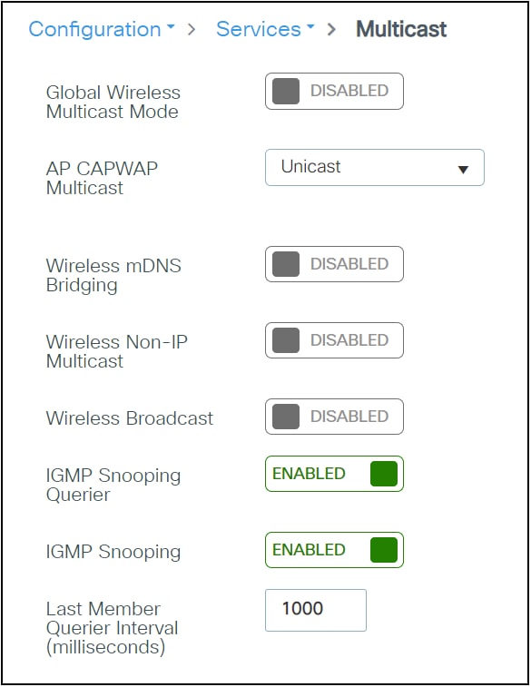
WLC multicast configuration
The multicast-multicast delivery method does not require the controller to replicate each multicast packet received. The controller is configured for an unused multicast group address that each access point becomes a member of.
In Figure 62, the multicast group defined from the WLC to the AP is 239.0.0.65. When a client sends a multicast join to the WLAN, the AP forwards this join through the CAPWAP tunnel to the controller. The controller forwards this link-layer protocol onto its directly connected LAN connection that is the default VLAN for the associated WLAN of the client. The router that is local to the controller then adds this multicast group address to that interface for forwarding ((*,G)). When the network now forwards multicast traffic, the multicast address of 239.0.0.30 is forwarded to the controller. The controller then encapsulates the multicast packet into a CAPWAP multicast packet addressed to the multicast group address (239.0.0.65 in the figure) that is configured on the controller and forwarded to the network. Each access point on the controller receives this packet as a member of the controller multicast group. The access point then forwards the clients’ or servers’ multicast packet (239.0.0.30) as a broadcast to the WLAN/SSID identified within the CAPWAP multicast packet. To configure the multicast-multicast mode, navigate through the Catalyst 9800 UI to the configuration and, under Services->Multicast, enable Multicast in the AP CAPWAP Multicast option. See Figure 62.
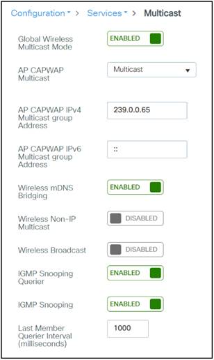
Multicast-multicast mode configuration
Internet Group Management Protocol (IGMP)
IP networks use IGMP and Protocol Independent Multicast (PIM) to manage multicast traffic across Layer 3 boundaries. When IGMP is enabled on your network, routers and other network devices use it to determine which hosts in the domain are interested in receiving multicast traffic.
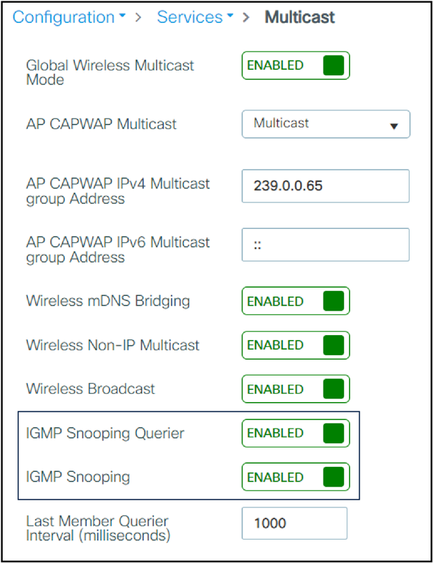
WLC IGMP configuration
Note: You must be cautious when using IGMPv3 with switches that are enabled for IGMP snooping. The IGMPv3 messages are different from the messages used in IGMPv1 and IGMPv2. If your switch does not recognize IGMPv3 messages, the hosts will not receive traffic when IGMPv3 is used.
IGMPv3 devices do not receive multicast traffic in the following cases:
● When IGMP snooping is disabled.
● When IGMPv2 is configured on the interface.
Ipv6 multicast allows a host to send a single data stream to a subset of all the hosts (group transmission) simultaneously. When Ipv6 Multicast over Multicast is configured, all the Aps join the Ipv6 multicast address, and the multicast traffic from the WLC to the AP flows over the Ipv6 multicast tunnel.
In mixed deployments (Ipv4 and Ipv6), the Aps might join the WLC over Ipv4 or Ipv6. To enable Multicast over Multicast in mixed deployments, configure both Ipv4 and Ipv6 multicast tunnels. Ipv4 Aps will have a unicast Ipv4 CAPWAP tunnel and will join the Ipv4 multicast group. Ipv6 Aps will have a unicast Ipv6 CAPWAP tunnel and will join the Ipv6 multicast group.
Table 15. Support matrix
| Platform |
Multicast support: Multicast over unicast |
Multicast support: Multicast over multicast |
| Cisco Catalyst 9800-40 Wireless Controller |
No |
Yes |
| Cisco Catalyst 9800-80 Wireless Controller |
No |
Yes |
| Cisco Catalyst 9800 Wireless Controller for Cloud – small template |
Yes |
Yes |
| Cisco Catalyst 9800 Wireless Controller for Cloud – medium template |
No |
Yes |
| Cisco Catalyst 9800 Wireless Controller for Cloud – large template |
No |
Yes |
| Cisco Catalyst 9800-L Wireless Controller |
Yes |
Yes |
Verifying the multicast connection between the controller and the AP
The Catalyst 9800 Series controllers initiate a ping request that passes through the CAPWAP multicast tunnel onto the CAPWAP multicast receiver, which is the AP. In response, the AP pings the packets for the CAPWAP multicast group IP address and sends the response back to the controller. You can view the statistics on the AP for transmitted and received traffic to analyze the data that is sent and received through the multicast tunnel. Alternatively, you can verify by enhancing the existing statistics on the AP for transmitted and received traffic to explicitly list the joins, leaves, and data packets transmitted and received through the multicast tunnel.
To confirm that the Aps receive Multicast-to-Multicast (MOM) traffic sent by the controller, use the following command “show ap multicast mom” in the WLC.
Directed Multicast Service (DMS)
The DMS feature allows a client to ask an AP to transmit multicast packets as unicast frames. After receiving this request, the AP buffers the multicast traffic for the client and transmits it as unicast frames when the client wakes up. This allows the client to receive the multicast packets that were ignored while in sleep mode (to save battery power) and also ensures Layer 2 reliability. The unicast frames are transmitted to the client at a potentially higher wireless link rate, which enables the client to receive the packet quickly by enabling the radio for a shorter duration, thus saving more battery power. Without DMS, the client must wake up at each Delivery Traffic Indication Map (DTIM) interval to receive multicast traffic.
Guest networks are pervasive nowadays, and almost every wireless deployment comes with the requirement for at least one guest SSID. The introduction of WLAN technologies in the enterprise has changed the way corporations and small to medium-sized businesses function by freeing staff and network resources from the constraints of fixed network connectivity.
WLANs have also changed how individuals access the internet and their corporate networks from public locations. The advent of public WLAN hotspots has caused mobile workers to become accustomed to being able to access their corporate network from practically anywhere.
The paradigm of public access has extended to the enterprise itself. Our highly mobile, information-on-demand culture requires on-demand network connectivity. For this reason, enterprise guest access services are becoming increasingly important and a necessity in the corporate environment.
While there is broad recognition that guest networking is becoming increasingly important, there is also well-founded apprehension over how to safeguard internal corporate information and infrastructure assets. When implemented correctly, an enterprise that implements a guest access solution will most likely improve its overall security posture because of the network audits associated with the implementation process.
In addition to improving overall security, implementing a guest access network offers these additional general benefits:
● Authentication and authorization control of guests based on variables including date, duration, and bandwidth.
● An audit mechanism to track who is currently using, or has used, the network.
Additional benefits of a wireless-based guest access include the following:
● It provides wider coverage by including areas such as lobbies and other common areas that otherwise might not have been wired for network connectivity.
● It removes the need for designated guest access areas or rooms.
Wireless guest access overview
Ideally, the implementation of a wireless guest network uses as much of an enterprise’s existing wireless and wired infrastructure as possible to avoid the cost and complexity of building a physical overlay network. When this is the case, the following additional elements and functions are needed:
● A dedicated guest WLAN/SSID: Implemented throughout the campus wireless network wherever guest access is required.
● Guest traffic segregation: Requires implementing Layer 2 or Layer 3 techniques across the campus network to restrict where guests are allowed to go.
● Access control: Involves using imbedded access control functionality within the campus network or implementing an external platform to control guest access to the internet from the enterprise network.
● Guest user credential management: A process by which a sponsor or lobby administrator can create temporary credentials on behalf of a guest. This function might be resident within an access control platform, or it might be a component of AAA or some other management system.
● Guest tunneling is supported only in a centrally switched solution, and it is not supported in the FlexConnect local switching solution.
Guest access using the Cisco wireless solution
The Cisco Unified Wireless Network solution offers a flexible, easy-to-implement method for deploying wireless guest access by using EtherIP (RFC 3378) within the centralized architecture. EtherIP is used to create a tunnel across a Layer 3 topology between two WLC endpoints. The benefit of this approach is that there are no additional protocols or segmentation techniques that must be implemented to isolate guest traffic from the enterprise.
The guest access solution is self-contained and does not require any external platforms to perform access control, web portal, or AAA services. All these functions are configured and run within the anchor controller. However, the option exists to implement one or all of these functions externally and is discussed later in this section.
The anchor function, which includes tunnel termination, web authentication, and access control is supported on the following Catalyst 9800 Series platforms.
● Cisco Catalyst 9800-80 Wireless Controller
● Cisco Catalyst 9800-40 Wireless Controller
● Cisco Catalyst 9800-L Wireless Controller
● Cisco Catalyst 9800-CL Wireless Controller (private cloud)
Table 16. Supported controllers
| Controller name |
Supported as guest anchor |
Supported as guest foreign |
| Cisco Catalyst 9800-40 Wireless Controller |
Yes |
Yes |
| Cisco Catalyst 9800-80 Wireless Controller |
Yes |
Yes |
| Cisco Catalyst 9800-CL Wireless Controller |
Yes |
Yes |
| Cisco Catalyst 9800-L Wireless Controller |
Yes |
Yes |
| Cisco Catalyst 9800 Embedded Wireless Controller for Switch |
No |
No |
Auto anchor mobility to support wireless guest access
Auto anchor mobility, or guest WLAN mobility, is a key feature of the Cisco Unified Wireless Network solution. It offers the ability to map a provisioned guest WLAN to one or more (anchor) WLCs by using an EoIP tunnel. Auto anchor mobility allows a guest WLAN and all associated guest traffic to be transported transparently across an enterprise network to an anchor controller that resides in the internet DMZ.
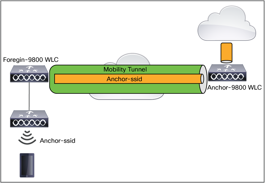
Catalyst 9800 Series mobility tunnel
Anchor controller redundancy N+1
The Cisco Unified Wireless Network supports “guest N+1” redundancy capability in the auto anchor/mobility functionality. This feature introduced an automatic ping function that enables a foreign controller to proactively ping anchor controllers to verify control and data path connectivity. In the event of failure or if an active anchor becomes unreachable, the foreign controller does the following:
● Automatically detects that the anchor has become unreachable.
● Automatically disassociates any wireless clients that were previously associated with the unreachable anchor.
● Automatically reassociates wireless client(s) to an alternate anchor WLC.
With guest N+1 redundancy, two or more anchor WLCs can be defined for a given guest WLAN.
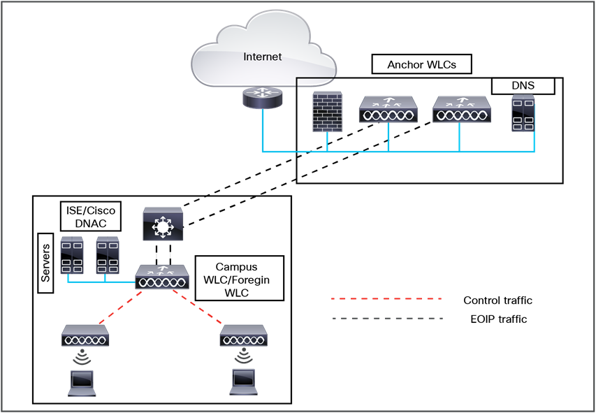
Anchor N+1 redundancy
Anchor controller redundancy priority
The guest anchor priority feature provides a mechanism that provides "active/standby" load distribution among the anchor WLCs. This is achieved by assigning a fixed priority to each anchor WLC by distributing the load to the highest-priority WLC, in round-robin fashion if WLCs have the same priority value.
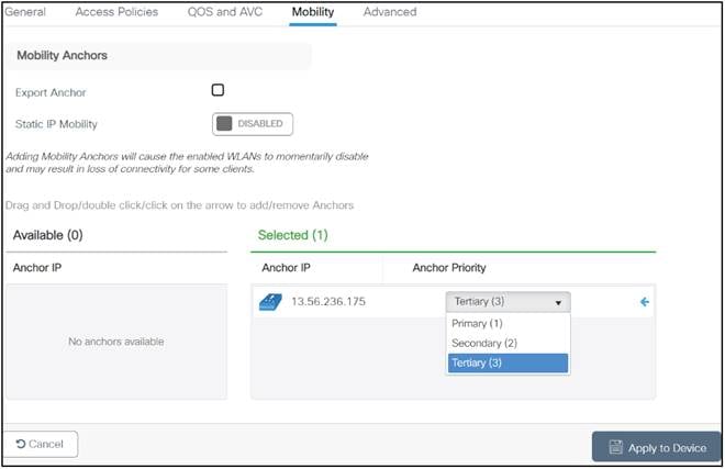
Mobility priority configuration
The wireless guest access feature comprises the following functions:
● The guest anchor controller is the point of presence for a client.
● The guest anchor controller provides internal security by forwarding the traffic from a guest client to a Cisco WLC in the Demilitarized Zone (DMZ) network through the anchor controller.
● The guest foreign controller is the point of attachment of the client.
● The guest foreign controller is a dedicated guest WLAN or SSID and is implemented throughout the campus wireless network wherever guest access is required. A WLAN with a mobility anchor (guest controller) configured on it identifies the guest WLAN.
● Guest traffic segregation implements Layer 2 or Layer 3 techniques across the campus network to restrict the locations where guests are allowed.
● Guest user-level QoS is used for rate limiting and shaping, although it is widely implemented to restrict the bandwidth usage for a guest user.
● Access control involves using embedded access control functionality within the campus network or implementing an external platform to control guest access to the internet from the enterprise network.
● Authentication and authorization of guests are based on variables, including date, duration, and bandwidth.
● An audit mechanism tracks who is currently using, or has used, the network.
● Wider coverage is provided by including areas such as lobbies and other common areas that are otherwise not wired for network connectivity.
● The need for designated guest access areas or rooms is removed.
The Cisco centralized guest access solution offers a built-in web portal that is used to solicit guest credentials for authentication and offers simple branding capabilities, along with the ability to display a disclaimer or acceptable use policy information.
The web portal page is available on all Cisco WLC platforms and is invoked by default when a WLAN is configured for Layer 3 web policy-based authentication.
If a more customized page is required, administrators have the option of importing and locally storing a customized page. Additionally, if an enterprise wants to use an external web server, the controller can be configured to redirect to it in place of using the internal server.
When a wireless guest logs in through the web portal, the controller handles the authentication in the following order:
1. The controller checks its local database for username and password and, if present, grants access. If no user credentials are found, then:
2. The controller checks to see if an external RADIUS server has been configured for the guest WLAN (under WLAN configuration settings). If so, the controller creates a RADIUS access-request packet with the username and password and forwards it to the selected RADIUS server for authentication.
If no specific RADIUS servers have been configured for the guest WLAN:
3. The controller checks its global RADIUS server configuration settings. Any external RADIUS servers configured with the option to authenticate "network" users are queried with the guest user credentials. Otherwise, if no RADIUS servers have "network user" checked, and the user has not authenticated through steps 1 or 2 above, authentication fails.
WLC and the guest account management (lobby ambassador) capabilities can be used only to create and apply guest user credentials for local authentication on the WLC. However, there may be cases in which an enterprise already has an existing guest management/authentication solution deployed as part of a wired guest access or NAC solution. If this is the case, the anchor controller/guest WLAN can be configured to forward web portal authentication to an external RADIUS server, as described above in Guest User Authentication.
The default protocol used by the controller to authenticate web users is Password Authentication Protocol (PAP). If you are authenticating web users to an external AAA server, be sure to verify the protocols supported by that server.
The following is a list of features supported by Cisco guest access:
● Sleeping clients
● FQDN
● AVC (AP upstream and downstream)
● Native profiling
● Open authentication
● OpenDNS
● Supported security methods:
◦ MAB Central Web Authentication (CWA)
◦ Local Web Authentication (LWA)
◦ LWA on MAB failure
◦ 802.1X + CWA
◦ 802.1X
● SSID QoS upstream and downstream (foreign)
● AP/ client SSO
● Static IP roaming
● Client IPv6
● Roaming across controllers
● VLAN persistence
● RADIUS accounting
● QoS: Client-level rate limiting
● Guest anchor load balancing
● Workgroup bridges (WGB)
Note: In a guest access scenario, accounting is always performed at the foreign controller for all authentication methods.
Load balancing among multiple guest controllers
● You can configure export anchors to load-balance large volumes of guest clients. For a single export foreign guest WLAN configuration, up to 72 controllers are allowed. To configure mobility guest controllers, use a mobility anchor IP address.
● You can specify primary anchors with priority (1,3) and choose another anchor as backup in case of failure.
● In a multianchor scenario, when the primary anchor goes down, the clients are disconnected from the primary anchor and join the secondary anchor.
Guidelines and limitations for wireless guest access
● Match the security profiles under the WLAN on both guest foreign and guest anchor.
● VLAN persistence is available starting from Cisco IOS XE Release 17.3. Users can carry the same VLAN when roaming across different profiles.
● Match the policy profile attributes, such as NAC and AAA override, on both the guest foreign and guest anchor controllers.
● On export anchor, the WLAN profile name and policy profile name is chosen when a client joins at runtime, and the same should match with the guest foreign controller.
For mobility guest scenarios, there are two main controller roles:
● Foreign controller: This WLC owns the Layer 2 or wireless side. It has APs connected to it. All client traffic for the anchored WLANs is encapsulated into the mobility tunnel to be sent to the anchor; it does not exit locally.
● Anchor controller: This is the layer 3 exit point. It receives the mobility tunnels from the foreign controllers and decapsulates or terminates the client traffic into the exit point (VLAN). This is the point where the clients are seen in the network, thus the anchor name.
Access points on the foreign WLC broadcast the WLAN SSIDs and have a policy tag assigned that links the WLAN profile with the corresponding policy profile. When a wireless client connects to this SSID, the foreign controller sends both the SSID name and policy profile as part of the client information to the anchor WLC. Upon receipt, the anchor WLC checks its own configuration to match the SSID name as well as policy profile name. Once the anchor WLC finds a match, it applies the corresponding configuration and exit point to the wireless client. Therefore, it is mandatory that the WLAN and policy profile names and configurations match on both foreign and anchor Catalyst 9800 Series WLCs, except for a VLAN under the policy profile.
Network diagram
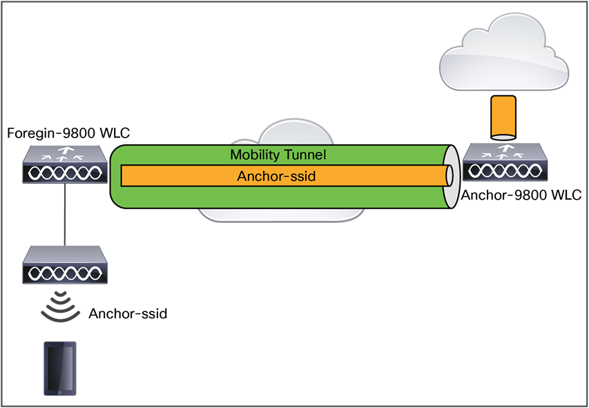
Guest network diagram
For detailed information on guest configuration, see Configure WLAN Anchor Mobility Feature on Catalyst 9800: https://www.cisco.com/c/en/us/support/docs/wireless/catalyst-9800-series-wireless-controllers/213912-configure-mobility-anchor-on-catalyst-98.html.
The Hotspot 2.0 feature enables IEEE 802.11 devices to interwork with external networks. The interworking service aids network discovery and selection, enabling information transfer from external networks. It provides information to the stations about the networks before association.
Interworking not only helps users within the home, enterprise, and public access domains, but also assists manufacturers and operators to provide common components and services for IEEE 802.11 customers. These services are configured on a per-WLAN basis on the Cisco controller.
Hotspot 2.0, also known as HS2 and Wi-Fi Certified Passpoint, is based on the IEEE 802.11u and Wi-Fi Alliance Hotspot 2.0 standards. It seeks to provide better bandwidth and services on demand to end users.
The Hotspot 2.0 feature allows mobile devices to join a Wi-Fi network automatically, including during roaming, when the devices enter the Hotspot 2.0 area.
The Hotspot 2.0 feature has four distinct parts:
● Hotspot 2.0 beacon advertisement: Allows a mobile device to discover Hotspot 2.0-compatible and 802.11u-compatible WLANs.
● Access Network Query Protocol (ANQP) queries: Sends queries about the networks from IEEE 802.11 devices, such as network type (private or public), connectivity type (local network, internet connection, and so on), or the network providers supported by a given network.
● Online sign-up: Allows a mobile device to obtain credentials to authenticate itself with the Hotspot 2.0 or WLAN.
● Authentication and session management: Provides authentication (802.1X) and management of the STA session (session expiration, extension, and so on).
In order to mark a WLAN as Hotspot 2.0-compatible, the 802.11u-mandated information element and the Hotspot 2.0 information element are added to the Basic Service Set (BSS) beacon advertised by the corresponding AP and in WLAN probe responses.
The Hotspot 2.0 feature supports only Local mode or FlexConnect mode (central switching and central authentication).
The following figure shows a standard deployment of the Hotspot 2.0 network architecture:
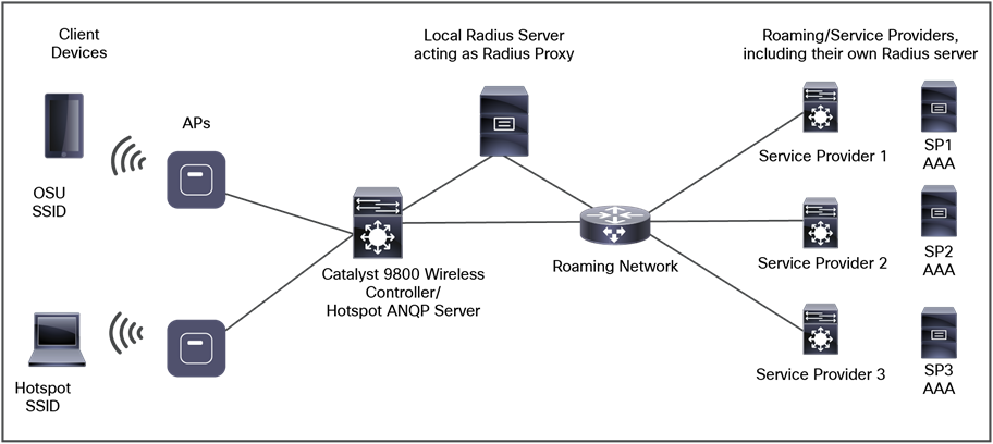
Hotspot 2.0 deployment topology
For Hotspot 2.0 configurations, refer to the Hotspot 2.0 guide: https://www.cisco.com/c/en/us/td/docs/wireless/controller/9800/17-1/config-guide/b_wl_17_11_cg/hotspot2.pdf.
Beginning with Cisco IOS XE Amsterdam Release 17.2.1, the controller supports OpenRoaming, which enables mobile users to roam across Wi-Fi and cellular networks automatically and seamlessly.
The new configuration template of the OpenRoaming ANQP server simplifies the task of setting up a Hotspot 2.0 ANQP server. When you configure OpenRoaming, fixed ANQP parameters are automatically populated.
You can configure different identity types by defining roaming organizational identifiers. The Organizational Unique Identifier (OUI) is a three-octet number that identifies the types of organizations available in each roaming consortium. The OUI list determines the type of identities allowed to roam into the network. The default configuration allows all the identities on the access network. However, access networks can customize the Roaming Consortium Organisation Identifier (RCOI) they advertise.
You can configure three types of policies for access networks:
● Allow all: Accepts users from any Identity Provider (IDP), with any privacy policy.
● Real ID: Accepts users from any IDP, but only with a privacy policy that shares real identity (anonymous not accepted).
● Custom: Accepts users of select identity types and privacy policies associated with the identity types – basically, all the other RCOIs.
Users can select the following privacy modes:
● Anonymous
● Share real identity
This section provides design and deployment guidelines for the deployment of secure enterprise, campus, and metropolitan Wi-Fi networks within Cisco wireless mesh networking, a component of the Cisco Unified Wireless Network solution.
For more detailed information about Cisco wireless mesh networking, including configuration and deployment, refer to the Mesh Deployment Guide for Cisco Catalyst 9800 Series Wireless Controllers: https://www.cisco.com/c/dam/en/us/td/docs/wireless/controller/9800/17-1/deployment-guide/c9800-mesh-rel-17-1.pdf.
Mesh networking employs Cisco Aironet 1540, 1560, or 1570 Series access points and the latest Catalyst 9124AX Series outdoor mesh access points; Catalyst 9800 Series wireless controllers; and Cisco DNA Center to provide scalable, central management and mobility between indoor and outdoor deployments. The CAPWAP protocol manages the connection of mesh access points to the network.
End-to-end security within the mesh network is supported by employing AES encryption between the wireless mesh APs and WPA2/WPA3 clients. This section also outlines RF components to consider when designing an outdoor network.
The features described in this section are for the following outdoor AP products:
● Cisco Catalyst 9124AX Series outdoor mesh access points
● Cisco Aironet 1560 (1562) Series outdoor mesh access points
● Cisco Aironet 1540 (1542) Series outdoor mesh access points
● Cisco Aironet 1570 (1572) Series outdoor mesh access points
Note: 1570 Series outdoor APs are not supported in Cisco DNA Center
● Cisco Aironet Wave 1 indoor APs: 1700, 2700, and 3700 series.
● Cisco Aironet Wave 2 indoor APs: 1815i, 1815m, 1830, 1850, 2800, 3800, and 4800 Series.
● Mesh features in Cisco Catalyst 9800 Series wireless controllers.
● Mesh features in Cisco Prime Infrastructure and Cisco DNA Center.
The Cisco wireless mesh network has four core components:
● Cisco Catalyst 9800 Series and Cisco IOS XE.
● Cisco Aironet and Catalyst access points.
● Cisco Prime Infrastructure and Cisco DNA Center.
● Mesh software architecture.
Mesh networking employs Cisco Aironet outdoor mesh APs and indoor mesh APs along with the Cisco WLC and Cisco Prime Infrastructure and Cisco DNA Center to provide scalable, central management and mobility between indoor and outdoor deployments. The CAPWAP protocol manages the connection of mesh access points to the network.
For Mesh mode, an AP should be configured with Bridge mode. Access points within a mesh network operate in one of the following two ways:
● Root AP (RAP)
● Mesh AP (MAP)
Note: All APs are configured and shipped as mesh APs. To use an APs as a RAP, you must reconfigure the mesh AP as a RAP. In all mesh networks, ensure that there is at least one RAP.
While the RAPs have wired connections to their controller, MAPs have wireless connections to their controller via the RAP or another MAP. MAPs communicate among themselves and back to the RAP using wireless connections over the 802.11a/n/ac/ax radio backhaul. MAPs use the Cisco Adaptive Wireless Path Protocol (AWPP) to determine the best path through the other mesh access points to the controller.
A mesh access point establishes an AWPP link with a parent mesh AP that is already connected to the controller before starting CAPWAP discovery.
Note: The RAP or MAP does not generate a Bridge Protocol Data Unit (BPDU) itself. However, the RAP or MAP forwards the BPDU to upstream devices if the RAP or MAP received the BPDU from its connected wired or wireless interface across the network.
This figure shows the relationship between RAPs and MAPs in a mesh network.
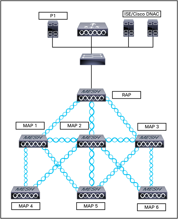
Simple mesh network hierarchy
Wireless mesh networks can simultaneously carry two different traffic types:
● WLAN client traffic
● MAP Ethernet port traffic
WLAN client traffic terminates on the controller, and the Ethernet traffic terminates on the Ethernet ports of the mesh APs.
Access to the WLAN mesh for mesh APs is managed by the following authentication methods:
● MAC authentication: Mesh APs are added to a database that can be referenced to ensure that they are provided access to a given controller and mesh network.
● External RADIUS authentication: Mesh APs can be externally authorized using a RADIUS server such as Cisco ISE that supports the client authentication type of EAP-FAST with certificates and WPA2/PSK on the Catalyst 9800 Series.
Membership in the WLAN mesh network for mesh APs is controlled by the Bridge Group Names (BGNs). Mesh APs can be placed in similar bridge groups to manage membership or provide network segmentation.
Enterprise 11n/ac mesh is added to the Catalyst 9800 controller features to work with the 802.11n/ac APs. Enterprise 11ac/ax mesh features are compatible with non-802.11ac mesh but add higher backhaul and client access speeds. The 802.11ac indoor APs are two-radio Wi-Fi infrastructure devices for select indoor deployments. One radio can be used for local (client) access for the AP, and the other radio can be configured for wireless backhaul. If Universal Backhaul Access is enabled, the 5-GHz and 2.4–GHz radios in Release 17.1 can be used for local (client) access as well as backhaul. Enterprise 11ac mesh supports point-to-point, point-to-multipoint, and mesh types of architectures.
You have a choice of ordering indoor APs in the bridge mode, so that these access points can be used directly as mesh APs. If you have these APs in a local mode (non-mesh), you must connect the APs to the controller and change the mode to the bridge mode (mesh). This scenario can become cumbersome, particularly if the volume of APs being deployed is large and if the APs are already deployed in the local mode for traditional non-mesh wireless coverage.
Cisco outdoor mesh access points
In addition to the mesh mode, the mesh APs can operate in the following modes:
● Local mode: In this mode, the AP can handle clients on its assigned channel or while monitoring all channels on the band over a 180-second period. During this time, the AP listens on each channel for 50 ms for rogue client beacons, noise floor measurements, interference, and IDS events. The AP also scans for CleanAir interference on the channel.
● FlexConnect mode: FlexConnect mode enables you to configure and control APs in a branch or remote office from the corporate office through a WAN link without having to deploy a controller in each office. This mode can switch client data traffic locally and perform client authentication locally when the connection to the controller is lost. When connected to the controller, an AP in FlexConnect mode can also tunnel traffic back to the controller.
● Flex+Mesh mode: In this mode, both the FlexConnect and Bridge mode configuration options are available on the access point.
● Monitor mode: In this mode, the AP radios are in the receive state. The AP scans all the channels every 12 seconds for rogue client beacons, noise floor measurements, interference, IDS events, and CleanAir intruders.
● Rogue Detector mode: In this mode, the AP radio is turned off, and the AP listens only to the wired traffic. The controller passes the APs that are configured as rogue detectors as well as lists of suspected rogue clients and AP MAC addresses. The rogue detector listens for ARP packets and can be connected to all broadcast domains through a trunk link.
● Sniffer mode: In this mode, the AP captures and forwards all packets on a channel to a remote device that decodes the packets with packet analyzer software such as Wireshark.
● Bridge mode: In this mode, the AP is configured to build a wireless mesh network where wired network cabling is not available.
Both the 2.4-GHz and 5-GHz frequency bands are supported on the indoor and outdoor access points.
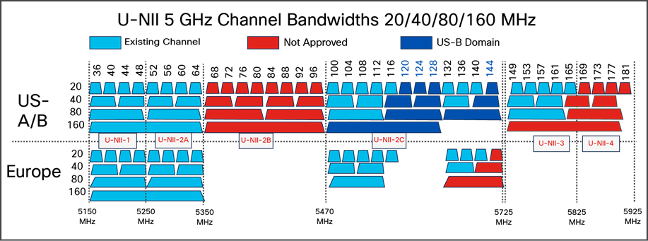
Frequency bands supported by 802.11a radios on mesh outdoor APs
● FCC United States U-NII-1: This band can now be used indoors, and outdoors maximum power is increased to 30 dBm (1W), assuming the antenna is 6 dBi. Power should be reduced by 1 dB for every dB in antenna gain that exceeds 6 dBi.
When used outdoors, Effective Isotropic Radiated Power (EIRP) in the upward direction above 30 degrees is limited to 125 mW (20.9 dBm).
● U-NII-2A and U-NII2C: Must include DFS radar detection.
Terminal Doppler Weather Radar (TWDR) bands (channels 120, 124, and 128) are now available with new DFS test requirements.
● U-NII-3: Band extended from 5825 MHz to 5850 MHz
● Europe U-NII-1: 23 dBm maximum; not permitted for outdoor use
● U-NII-2A: 23 dBm maximum; not permitted for outdoor use
● U-NII-2C: 30 dBm maximum
● U-NII-3: Available only in the UK at 23 dBm for indoor use only
Dynamic Frequency Selection (DFS)
Previously, devices employing radar operated in frequency sub-bands without other competing services. However, controlling regulatory bodies are attempting to open and share these bands with new services such as wireless mesh LANs (IEEE 802.11).
To protect existing radar services, the regulatory bodies require that devices wishing to share the newly opened frequency sub-bands behave in accordance with the DFS protocol. DFS dictates that to be compliant, a radio device must be capable of detecting the presence of radar signals. When a radio detects a radar signal, it is required to stop transmitting to for at least 30 minutes to protect that service. The radio then selects a different channel to transmit on, but only after monitoring it. If no radar is detected on the projected channel for at least one minute, the new radio service device may begin transmissions on that channel.
The AP performs a DFS scan on the new DFS channel for 60 seconds. However, if a neighboring AP is already using that new DFS channel, the AP does not perform the DFS scan.
The process for a radio to detect and identify a radar signal is a complicated task that sometimes leads to incorrect detections. Incorrect radar detections can occur due to many factors, including uncertainties regarding the RF environment and the ability of the AP to reliably detect actual on-channel radar.
The 802.11h standard addresses DFS and Transmit Power Control (TPC) as it relates to the 5-GHz band. Use DFS to avoid interference with radar and TPC to avoid interference with satellite feeder links.
Antenna choice is a vital component of any wireless network deployment. There are two broad types of antennas:
● Directional
● Omnidirectional
Each type of antenna has a specific use and is most beneficial in specific types of deployments. Because antennas distribute RF signal in large lobed coverage areas determined by antenna design, successful coverage is heavily reliant on antenna choice.
An antenna gives a mesh AP three fundamental properties: gain, directivity, and polarization:
Gain: A measure of the increase in power. Gain is the amount of increase in energy that an antenna adds to an RF signal.
Directivity: The shape of the transmission pattern. If the gain of the antenna increases, the coverage area decreases. The coverage area or radiation pattern is measured in degrees. These angles are measured in degrees and are called beamwidths.
Note: Beamwidth is defined as a measure of the ability of an antenna to focus radio signal energy on a particular direction in space. Beamwidth is usually expressed in Note degrees HB (Horizontal Beamwidth); usually, the most important one is expressed in a VB (Vertical Beamwidth) (up and down) radiation pattern. When viewing an antenna plot or pattern, the angle is usually measured at half-power (3 dB) points of the main lobe when referenced to the peak effective radiated power of the main lobe.
An 8-dBi antenna transmits with a horizontal beamwidth of 360 degrees, causing the radio waves to disperse power in all directions. Therefore, radio waves from an 8-dBi antenna do not go nearly as far as radio waves sent from a 14-dBi patch antenna (or a third-party dish) that has a narrower beamwidth (less than 360 degrees).
Polarization: The orientation of the electric field of the electromagnetic wave through space. Antennas can be polarized either horizontally or vertically, though other kinds of polarization are available. Both antennas in a link must have the same polarization to avoid an additional unwanted loss of signal.
To improve performance, an antenna can sometimes be rotated to alter polarization, which reduces interference. A vertical polarization is preferable for sending RF waves down concrete canyons, and horizontal polarization is generally preferable for wide area distribution. Polarization can also be harnessed to optimize for RF bleed-over when reducing RF energy to adjacent structures is important. Most omnidirectional antennas ship with vertical polarization as their default.
A wide variety of antennas are available to provide flexibility when you deploy the mesh APs over various terrains. Refer to the applicable access point data sheet or ordering guide for a list of supported antennas.
See the Cisco Aironet and Catalyst Antennas and Accessories Reference Guide at https://www.cisco.com/c/en/us/products/collateral/wireless/aironet-antennas-accessories/product_data_sheet09186a008008883b.html.
This guide discusses the deployment and design, limitations and capabilities, and basic theories of antennas, as well as installation scenarios, regulatory information, and technical specifications.
Flexible antenna port configuration
The AP needs to support a flexible antenna port configuration. Software changes are done to let the user configure the antennas to support either a single-band mode or dual-band mode.
Client access certified antennas (third-party antennas)
You can use third-party antennas with Wave 2 Aironet 1542, 1562, and 1572 APs. However, note the following:
● Cisco does not track or maintain information about the quality, performance, or reliability of the noncertified antennas and cables.
● RF connectivity and compliance are the customer's responsibility.
● Compliance is guaranteed only with Cisco antennas or antennas that are of the same design and gain as Cisco antennas.
● The Cisco Technical Assistance Center (TAC) has no training or customer history for third-party antennas and cables.
The wireless mesh solution with Cisco IOS XE 17.9.1 is supported on Catalyst 9800-CL virtual and hardware appliances such the 9800-80, 9800-40, and 9800-L.
Cisco Prime Infrastructure and Cisco DNA Center
Cisco DNA Center provides a graphical platform for wireless mesh planning, configuration, and management. Network managers can use Cisco DNA Center to design, control, and monitor wireless mesh networks from a central location.
With Cisco DNA Center, network administrators have a solution for RF prediction, policy provisioning, network optimization, troubleshooting, user tracking, security monitoring, and WLAN systems management. Graphical interfaces make WLAN deployment and operations simple and cost-effective. Detailed trending and analysis reports make Cisco DNA Center vital to ongoing network operations.
Cisco DNA Center runs on a server platform with an embedded database, which provides scalability that allows hundreds of controllers and thousands of Cisco mesh APs to be managed. Controllers can be located on the same LAN as Cisco DNA Center, on separate routed subnets, or across a wide-area connection.
CAPWAP is the provisioning and control protocol used by the controller to manage APs (mesh and non-mesh) in the network.
CAPWAP discovery on a mesh network
The process for CAPWAP discovery on a mesh network is as follows:
1. A mesh AP establishes a link before starting CAPWAP discovery, whereas a non-mesh AP starts CAPWAP discovery using a static IP for the mesh AP, if any.
2. The mesh AP initiates CAPWAP discovery using a static IP for the mesh AP on the Layer 3 network or searches the network for its assigned primary, secondary, or tertiary controller. A maximum of 10 attempts are made to connect.
Note: The mesh AP searches a list of controllers configured on the AP (primed) during setup.
3. If step 2 fails after 10 attempts, the mesh AP falls back to DHCP and attempts to connect in 10 tries.
4. If both steps 2 and 3 fail and there is no successful CAPWAP connection to a controller.
5. If there is no discovery after attempting steps 2, 3, and 4, the mesh AP tries the next link.
Dynamic MTU detection
If the MTU is changed in the network, the AP detects the new MTU value and forwards that to the controller to adjust to the new MTU. After both the AP and the controller are set at the new MTU, all data within their path is fragmented into the new MTU. The new MTU size is used until it is changed. The default MTU on switches and routers is 1500 bytes.
Adaptive Wireless Path Protocol (AWPP)
AWPP is designed specifically for wireless mesh networking to provide ease of deployment, fast convergence, and minimal resource consumption.
AWPP takes advantage of the CAPWAP WLAN, where client traffic is tunneled to the controller and is therefore hidden from the AWPP process. Also, the advance radio management features in the CAPWAP WLAN solution are available to the wireless mesh network and do not have to be built into AWPP.
AWPP enables a remote AP to dynamically find the best path back to a RAP for each MAP that is part of the RAP BGN. Unlike traditional routing protocols, AWPP takes RF details into account.
To optimize the route, a MAP actively solicits neighbor MAPs. During the solicitation, the MAP learns all the available neighbors back to a RAP, determines which neighbor offers the best path, and then synchronizes with that neighbor. The path decisions of AWPP are based on the link quality and the number of hops.
AWPP automatically determines the best path back to the CAPWAP controller by calculating the cost of each path in terms of the signal strength and number of hops. After the path is established, AWPP continuously monitors conditions and changes routes to reflect changes in conditions. AWPP also performs a smoothing function to signal condition information to ensure that the ephemeral nature of RF environments does not impact network stability.
Traffic flow
The traffic flow within the wireless mesh can be divided into three components:
● Overlay CAPWAP traffic that flows within a standard CAPWAP access point deployment; that is, CAPWAP traffic between the CAPWAP AP and the CAPWAP controller.
● Wireless mesh data frame flow.
● AWPP exchanges.
As the CAPWAP model is well known and AWPP is a proprietary protocol, only the wireless mesh data flow is described. The key to the wireless mesh data flow is the address fields of the 802.11 frames being sent between mesh APs.
An 802.11 data frame can use up to four address fields: receiver, transmitter, destination, and source. The standard frame from a WLAN client to an AP uses only three of these address fields because the transmitter address and the source address are the same. However, in a WLAN bridging network, all four address fields are used because the source of the frame might not be the transmitter of the frame, because the frame might have been generated by a device behind the transmitter.
The figure below shows an example of this type of framing. The source address of the frame is MAP:03:70, the destination address of this frame is the controller (the mesh network is operating in Layer 2 mode), the transmitter address is MAP:D5:60, and the receiver address is RAP:03:40.
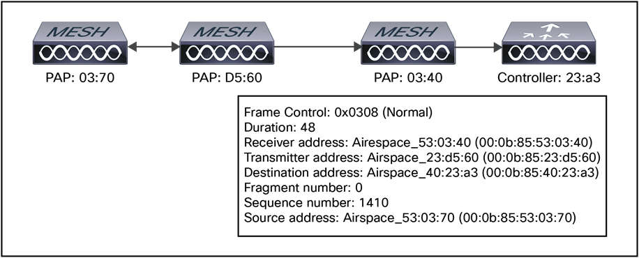
Wireless mesh frame
As this frame is sent, the transmitter and receiver addresses change on a hop-by-hop basis. AWPP is used to determine the receiver address at each hop.
The transmitter address is known because it is the current mesh AP. The source and destination addresses are the same over the entire path.
If the RAP controller connection is Layer 3, the destination address for the frame is the default gateway MAC address, because the MAP has already encapsulated the CAPWAP in the IP packet to send it to the controller and is using the standard IP behavior of using ARP to find the MAC address of the default gateway.
Each mesh AP within the mesh forms a CAPWAP session with a controller. WLAN traffic is encapsulated inside CAPWAP and is mapped to a VLAN interface on the controller. Bridged Ethernet traffic can be passed from each Ethernet interface on the mesh network and does not have to be mapped to an interface on the controller (see Figure 72).
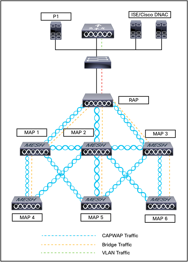
Logical bridge and WLAN mapping
Mesh neighbors, parents, and children
Relationships among mesh APs are as a parent, child, or neighbor (see Figure 73).
● A parent AP offers the best route back to the RAP based on its ease values. A parent can be either the RAP itself or another MAP.
◦ Ease is calculated using the SNR and link hop value of each neighbor. Given multiple choices, generally an AP with a higher ease value is selected.
● A child AP selects the parent AP as its best route back to the RAP.
● A neighbor AP is within RF range of another AP but is not selected as its parent or a child because its ease value is lower than that of the parent.
● Mesh networks are half duplex, meaning after the first hop (RAP to MAP) overall throughput is decreased by 50% for each additional hop (MAP to MAP). Where Ethernet bridging clients are used in MAPs and heavy traffic is passed, high throughput consumption nay result, which may cause the downlink MAPs to disassociate from the network due to throughput starvation.
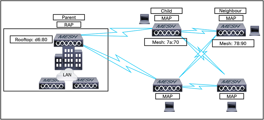
Parent, child, and neighbor relationships
Criteria for choosing the best parent
AWPP follows this process in selecting parents for a RAP or MAP with a radio backhaul:
1. A list of channels with a neighbor is generated by passive scanning in the scan state, which is a subset of all backhaul channels.
2. The channels with a neighbor are sought by actively scanning in the seek state, and the backhaul channel is changed to the channel with the best neighbor.
3. The parent is set to the best neighbor, and the parent-child handshake is completed in the seek state.
4. Parent maintenance and optimization occurs in the maintain state.
This algorithm is run at startup and whenever a parent is lost and no other potential parent exists, and it is usually followed by CAPWAP network and controller discovery. All neighbor protocol frames carry the channel information.
Parent maintenance occurs by the child node sending a directed NEIGHBOR_REQUEST to the parent and the parent responding with a NEIGHBOR_RESPONSE.
Parent optimization and refresh occurs by the child node sending a NEIGHBOR_REQUEST broadcast on the same channel on which its parent resides, and by evaluating all responses from neighboring nodes on the channel.
A parent mesh AP provides the best path back to a RAP. AWPP uses ease to determine the best path. Ease can be considered the opposite of cost, and the preferred path is the path with the higher ease.
Ease calculation
Ease is calculated using the SNR and hop value of each neighbor and applying a multiplier based on various SNR thresholds. The purpose of this multiplier is to apply a spreading function to the SNRs that reflects various link qualities.
The figure below shows a parent path selection process. In the figure, MAP2 prefers the path through MAP1 because the adjusted ease value (436906) though this path is greater than the ease value (262144) of the direct path from MAP2 to RAP.
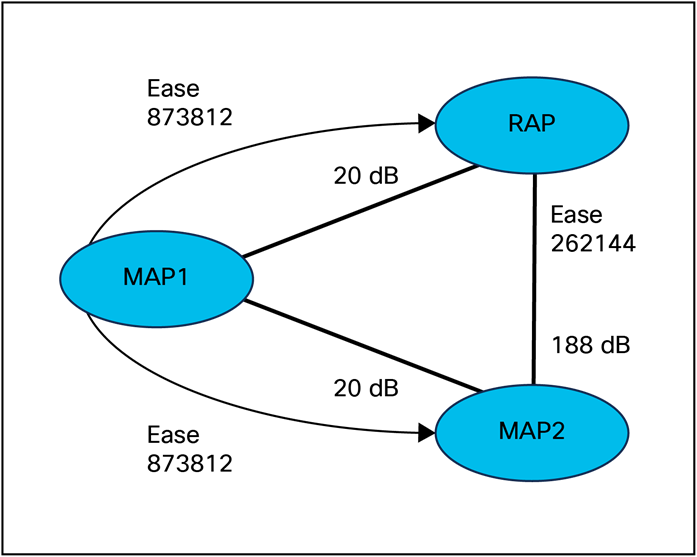
Parent path selection
Parent decision
A parent mesh AP is chosen by using the adjusted ease, which is the ease of each neighbor divided by the number of hops to the RAP: Adjusted ease = Min (ease at each hop) Hop count.
SNR smoothing
One of the challenges in WLAN routing is the ephemeral nature of RF, which must be considered when analyzing an optimal path and deciding when a change in path is required. The SNR on a given RF link can change substantially from moment to moment, and changing route paths based on these fluctuations result in an unstable network with severely degraded performance. To effectively capture the underlying SNR but remove moment-to moment fluctuations, a smoothing function is applied that provides an adjusted SNR.
In evaluating a potential neighbor against the current parent, the parent is given 20% of bonus ease on top of the parent's calculated ease, to reduce the ping-pong effect between parents. A potential parent must be significantly better for a child to make a switch. Parent switching is transparent to CAPWAP and other higher-layer functions.
Loop prevention
To ensure that routing loops are not created, AWPP discards any route that contains its own MAC address. That is, routing information apart from hop information contains the MAC address of each hop to the RAP; therefore, a mesh AP can easily detect and discard routes that loop.
Mesh AP roaming
Mesh APs can roam from one parent mesh AP to a new parent mesh AP. A parent mesh AP and the Catalyst 9800 will use the MESH_ROAM_REQUEST and MESH_ROAM_RESPONSE payloads to handle MAP roaming.
The Catalyst 9800 Series will support MAP roaming between parent mesh APs within the same controller and parent mesh APs across different controllers. MAP roaming across parent mesh APs connected to Aire-OS and Catalyst 9800 Series controllers in the same mobility group will be supported.
In a Cisco wireless outdoor mesh network, multiple mesh APs make up a network that provides a secure, scalable outdoor WLAN.
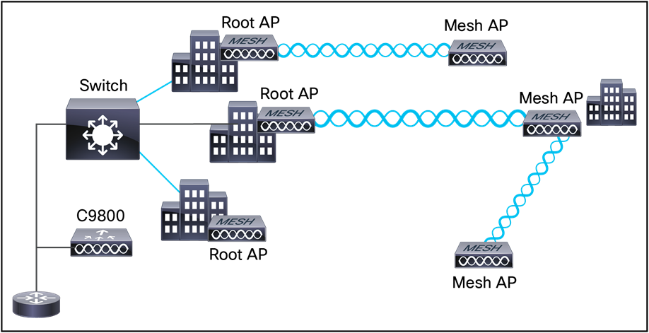
Wireless Mesh Topology
The three RAPs are connected to the wired network at each location and are located on the building roof. All the downstream APs operate as MAPs and communicate using wireless links. Both MAPs and RAPs can provide WLAN client access; however, the location of RAPs is often not suitable for providing client access. All three APs are located on the building roofs and are functioning as RAPs. These RAPs are connected to the network at each location.
Some of the buildings have onsite controllers to terminate CAPWAP sessions from the mesh APs, but this is not mandatory because CAPWAP sessions can be backhauled to a controller over a WAN.
Wireless backhaul at 5 and 2.4 GHz
In a Cisco wireless backhaul network, traffic can be bridged between MAPs and RAPs. This traffic can be from wired devices that are being bridged by the wireless mesh or CAPWAP traffic from the mesh APs. This traffic is always AES encrypted when it crosses a wireless mesh link such as a wireless backhaul.
AES encryption is established as part of the mesh AP neighbor relationship with other mesh APs. The encryption keys used between mesh APs are derived during the EAP authentication process.
By default, the backhaul interface for mesh APs is 802.11a/ac/ax. In certain countries the use of a mesh network with a 5-GHz backhaul network is not permitted, and even in countries where 5 GHz is permitted, the customer may prefer to use 2.4-GHz radio frequencies to achieve much larger mesh or bridge distances.
When a RAP gets a change of configuration from 5 to 2.4 GHz, the selection gets propagated from the RAP to all MAPs, and they will disconnect from the 5-GHz network and get reconnected at 2.4 GHz. During this process, the parent mesh AP does not send any messages to child MAPs about the change in backhaul slot. MAPs should detect the parent loss and connect to the parent AP after the scan in the new backhaul radio band.
Only RAPs are configured with the backhaul frequency of 5 GHz or 2.4 GHz.
You can configure the backhaul on mesh APs to accept client traffic over the 802.11 radio. This feature is identified as backhaul client access in the controller When this feature is disabled, backhaul traffic is transmitted only over the 802.11a/ac radio, and client association is allowed only over the second radio. Backhaul client access is disabled by default. After this feature is enabled, all mesh APs, except subordinate APs, and their child APs in daisy-chained deployments on Aironet 1540, 1560, and 1570 Series APs, reboot.
Point-to-multipoint wireless bridging
In a point-to-multipoint bridging scenario, a RAP acting as a root bridge connects multiple MAPs as non-root bridges with their associated wired LANs.
By default, this feature is disabled for all MAPs. If Ethernet bridging is used, you must enable it on the controller for the respective MAP and for the RAP.
This figure shows a simple deployment with one RAP and two MAPs, but this configuration is fundamentally a wireless mesh with no WLAN clients. Client access can still be provided with Ethernet bridging enabled, although if bridging between buildings, MAP coverage from a high rooftop might not be suitable for client access.
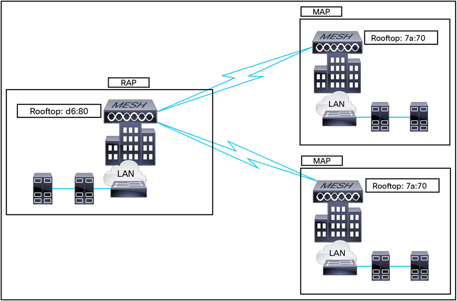
Point-to-multipoint bridging example
Point-to-point wireless bridging
In a point-to-point bridging scenario, an Aironet 1540, 1560, or 1570 Series mesh AP can be used to extend a remote network by using the backhaul radio to bridge two segments of a switched network. This is fundamentally a wireless mesh network with one MAP and no WLAN clients. Just as in point-to-multipoint networks, client access can still be provided with Ethernet bridging enabled, although if bridging between buildings, MAP coverage from a high rooftop might not be suitable for client access.
If you intend to use an Ethernet bridged application, we recommend that you enable the bridging feature on the RAP and on all MAPs in that segment.
You must verify that any switches attached to the Ethernet ports of your MAPs are not using VLAN Trunking Protocol (VTP). VTP can reconfigure the trunked VLANs across your mesh and possibly cause a loss of connection for your RAP to its primary Catalyst 9800 Series controller. An incorrect configuration can take down your mesh deployment.
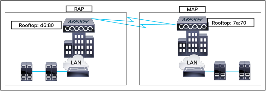
Point-to-point bridging example
The Aironet 1540, 1560, and 1570 Series APs and the Catalyst 9124AX Series APs have the capability to "daisy-chain" APs when they function as MAPs.
The daisy-chained MAPs can extend universal access by connecting a Local mode or FlexConnect mode Catalyst 9124AX to the Ethernet port of a MAP, thus extending the network to provide better client access.
In this case, the daisy-chained MAP is called the master MAP, and the MAP that is connected to the master MAP over Ethernet is called the subordinate MAP or subordinate RAP, since another wireless MAP can connect to the subordinate RAP if properly configured to prevent loops.
In daisy-chaining mode,
● The master MAP should be configured as a mesh AP.
● The subordinate MAP should be configured as a RAP.
● Daisy chaining should be enabled on both master and subordinate MAPs.
● Ethernet bridging should be enabled on all of the APs in Bridge mode. Enable Ethernet bridging in the mesh profile, and all Bridge mode APs in the sector should be mapped to the same mesh profile.
● VLAN support should be enabled on the wired RAP, subordinate MAP, and master MAP, along with proper native VLAN configuration.
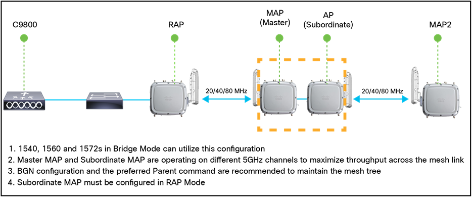
Daisy-chain topology
Flex+Mesh Wave 2 APs can be running in connected or standalone mode. Standalone mode in FlexConnect will undergo some changes to inherit standalone functionality for a mesh network. There is also another mode called abandoned mode discussed below.
Connected mode
A Wave 2 Flex+Mesh AP (RAP or child MAP) is in connected mode when it can access and join the Catalyst 9800 and can exchange periodic keep-alive messages with the Catalyst 9800. In this mode, a Flex+Mesh AP will be able to support locally and centrally switched WLANs. It will allow regular client and child mesh APs to join.
Standalone mode
A Wave 2 Flex+Mesh AP is in standalone mode if it loses connection to the controller but can access the local gateway. In this mode, the Wave 2 Flex+Mesh AP will disable all the centrally switched WLANs and keep the locally switched WLANs up and running. It will also allow new clients to join on locally switched WLANs using local authentication if the authentication server is reachable in the local network. Child mesh APs will NOT be allowed to join in this mode.
Abandoned mode or persistent SSID mode
A Wave 2 Flex+Mesh AP is in abandoned mode when it can no longer access the gateway IP and has no connectivity to the local network.
For security reasons, the Ethernet port on the MAPs is disabled by default. It can be enabled only by configuring Ethernet bridging on the RAP and the respective MAPs. This means that traffic from a wired client on a mesh AP gets bridged to the other clients in the mesh or to the wired infrastructure and beyond. A typical use of Ethernet ports is to connect cameras for monitoring the APs.
Both tagged and untagged packets are supported on secondary Ethernet interfaces.
Ethernet bridging must be enabled for the following two scenarios:
● When you want to use the mesh nodes as bridges.
● When you want to connect an Ethernet device such as a video camera on the MAP using its Ethernet port.
Ensure that Ethernet bridging is enabled for every parent mesh AP taking the path from the mesh AP in question to the controller. For example, if you enable Ethernet bridging on MAP2 in Hop 2, you must also enable Ethernet bridging on MAP1 (the parent MAP) and on the RAP connecting to the controller.
Ethernet bridging works without controller knowledge. This means that there’s no CAPWAP involved for Ethernet bridging. We use CAPWAP only for configuration purpose.
In a mesh environment with VLAN support for Ethernet bridging, the secondary Ethernet interfaces on MAPs can be assigned a VLAN individually, via “ap exec” commands. All backhaul bridge links, both wired and wireless, are trunk links with all VLANs enabled. Non-Ethernet bridged traffic, as well as untagged Ethernet bridged traffic travels along the mesh using the native VLAN of the APs in the mesh. This holds true for all the traffic to and from wireless clients that the APs are servicing.
The VLAN tagged packet will be tunneled through AWPP over wireless backhaul links.
Workgroup bridge interoperability with mesh infrastructure
A Workgroup Bridge (WGB) is a small standalone unit that can provide a wireless infrastructure connection for Ethernet-enabled devices. Devices that do not have a wireless client adapter to connect to the wireless network can be connected to the WGB through the Ethernet port. The WGB is associated with the root AP through the wireless interface, which means that wired clients get access to the wireless network.
A WGB is used to connect wired networks over a single wireless segment by informing the mesh AP of all the clients that the WGB has on its wired segment via Inter-Access Point Protocol (IAPP) messages. The data packets for WGB clients contain an additional MAC address in the 802.11 header (four MAC data headers, versus the normal three). The additional MAC in the header is the address of the WGB itself. This additional MAC address is used to route the packet to and from the clients.
WGB association is supported on all radios of every mesh AP.
In the current architecture, while an autonomous AP functions as a WGB, only one radio interface is used for controller connectivity, one Ethernet interface for wired client connectivity, and the other radio interface for wireless client connectivity. dot11radio 1 (5 GHz) can be used to connect to a controller (using the mesh infrastructure) and Ethernet interface for wired clients. dot11radio 0 (2.4 GHz) can be used for wireless client connectivity. Depending on the requirement, dot11radio 1 or dot11radio 0 can be used for client association or controller connectivity.
With two radios, one radio can be used for client access and the other radio can be used for accessing the APs. Having two independent radios performing two independent functions provides you better control and lowers the latency. Also, wireless clients on the second radio for the WGB do not get disassociated by the WGB when an uplink is lost or in a roaming scenario. One radio must be configured as a RAP (radio role), and the second radio must be configured as a WGB (radio role).
Note: If one radio is configured as a WGB, the second radio cannot be a WGB or a repeater in Cisco IOS XE Release 17.1.
The following features are not supported for use with a WGB:
● Idle timeout
● Web authentication: If a WGB associates to a web-authentication WLAN, the WGB is added to the exclusion list and all the WGB-wired clients are deleted (web-authentication WLAN is another name for a guest WLAN).
● For wired clients behind the WGB, MAC filtering, link tests, and idle timeout are not supported
Serial backhaul enables us to use different channels on different backhauls, which helps in reducing interference and maximizing throughput. The intention is that in units with third and fourth radios, two of the radios are reserved for backhaul.
By keeping radios on exclusive channels or frequency bands, we avoid the need to use the same shared wireless medium between the northbound and southbound traffic in a mesh tree-based network.
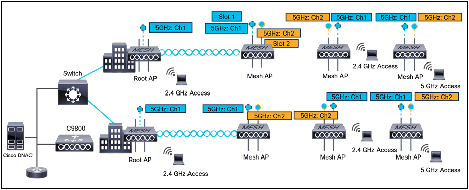
Mesh serial backhaul design
RAP uplink detection is made simple, and the teardown is triggered automatically from the RAP upon backhaul failure. Reduce detection time for RAP uplink backhaul failure by pinging the gateway at frequent intervals to monitor the uplink and introduce latency check as another criterion: gateway link check to confirm whether the latency is within the threshold. When the RAP loses the uplink, it should stop serving clients (disconnect clients and not broadcast SSID).
Mesh convergence is an important feature in reestablishing the connection to the Catalyst 9800 whenever a MAP loses the backhaul connection from its current parent, which could be a RAP or a successive level MAP.
Standard convergence
In this method, to detect a parent loss, MAP takes 21 seconds and for seek it takes 3 seconds per channel. The parent/neighbor keep-alive time will be 3 seconds.
Fast convergence
In this method, parent loss detection is reduced to 7 seconds and for seek 2 seconds per channel. By using the subset of channels, MAP will scan only in a subset of channels, which reduces the overall seek time. The parent/neighbor keep-alive time will be 3 seconds.
Very fast convergence
In this method, parent loss detection is reduced to 4 seconds and for seek 2 seconds per channel only on the subset of channels. The parent/neighbor keep-alive time will be 1.5 seconds.
Table 17. Mesh convergence time
| Convergence method |
Parent loss adjTimerMN-seconds |
Seek per channel adjTimer1-seconds |
Parent, neighbor keep alive adjTimerMP-seconds |
| Standard |
21 |
3 |
3 |
| Fast |
7 |
2 |
3 |
| Very Fast |
4 |
2 |
1.5 |
If a MAP gets stranded and fails to find a parent and connect to the Catalyst 9800, it will reboot after MESH_LWAPP_REBOOT_TIMER (40 minutes) expires. After this the existing standard convergence will be applied.
Cisco MAPs are interconnected over wireless links in a spanning tree-like topology. A MAP connected to the network via Ethernet uplink is designated as the root AP. AWPP is used to maintain and form the tree. When a MAP comes up, it tries to look for another MAP (parent) to join to reach the gateway eventually via a RAP. The same happens when a MAP lose connectivity with its existing parent. This procedure is known as mesh tree convergence. This feature aims to make the convergence procedure faster and more robust.
This procedure is time consuming. To simplify the process, we have introduced mesh background scanning and automatic parent selection. This feature is available in Cisco IOS XE starting with Release 17.11.1 in the Aironet 1562 and Catalyst 9124AX APs. This mechanism allows the MAP to find and connect faster to a better potential parent across channels and always maintain its uplink with the best parent.
Each outdoor wireless mesh deployment is unique, and each environment has its own challenges with available locations, obstructions, and network infrastructure. Requirements driven by expected users, traffic, and availability needs are also major design criteria.
The following sections describe a few system characteristics to consider when you design and build a wireless mesh network. Some of these characteristics apply to the backhaul network design and others to the CAPWAP controller design.
Wireless backhaul data rate
Backhaul is used to create only the wireless connection between the APs. The backhaul interface is 802.11a/n/ac, depending on the access point. The rate selection is important for effective use of the available RF spectrum. The rate can also affect the throughput of client devices, and throughput is an important metric used by industry publications to evaluate vendor devices.
Dynamic Rate Adaptation (DRA) introduces a process to estimate an optimal transmission rate for packet transmissions. It is important to select rates correctly. If the rate is too high, packet transmissions will fail, resulting in communication failure. If the rate is too low, the available channel bandwidth will not be used, resulting in inferior products and the potential for catastrophic network congestion and collapse.
Data rates also affect the RF coverage and network performance. Lower data rates, for example 6 Mbps, can extend farther from the AP than can higher data rates, for example 1300 Mbps. As a result, the data rate affects cell coverage and consequently the number of APs required. Different data rates are achieved by sending a more redundant signal on the wireless link, allowing data to be easily recovered from noise. The number of symbols sent out for a packet at the 1-Mbps data rate is higher than the number of symbols used for the same packet at 11 Mbps. Therefore, sending data at the lower bit rates takes more time than sending the equivalent data at a higher bit rate, resulting in reduced throughput.
A lower bit rate might allow a greater distance between MAPs, but there are likely to be gaps in the WLAN client coverage, and the capacity of the backhaul network is reduced. An increased bit rate for the backhaul network either requires more MAPs or results in a reduced SNR between MAPs, limiting mesh reliability and interconnection.
Controller planning
The following items affect the number of controllers required in a mesh network:
● The number of mesh APs (RAPs and MAPs) in the network.
● The wired network that connects the RAP and controllers can affect the total number of APs supported in the network. If this network allows the controllers to be equally available to all APs without any impact on WLAN performance, the APs can be evenly distributed across all controllers for maximum efficiency. If this is not the case, and controllers are grouped into various clusters or PoPs, the overall number of APs and coverage are reduced.
● The number of mesh APs (RAPs and MAPs) supported per controller.
● For clarity, non-mesh APs are referred to as local access points in the table below.
Table 18. Mesh and local APs supported by controller model
| Controller model |
Local AP support (non-mesh) |
Maximum possible mesh AP support |
| Catalyst 9800-80 |
6000 |
6000 |
| Catalyst 9800-40 |
2000 |
2000 |
| Catalyst 9800-CL |
1000 |
1000 |
| Catalyst 9800-L |
250 |
250 |
We recommend that you perform a radio site survey before installing the equipment. A site survey reveals problems such as interference, Fresnel zone, or logistics problems. A proper site survey involves temporarily setting up mesh links and taking measurements to determine whether your antenna calculations are accurate. Determine the correct location and antenna before drilling holes, routing cables, and mounting equipment.
Note: When power is not readily available, we recommend that you use an Uninterruptible Power Supply (UPS) to temporarily power the mesh link.
For more information on site planning and surveys, refer to the Mesh Deployment Guide for Cisco Catalyst 9800 Series Wireless Controllers: https://www.cisco.com/c/dam/en/us/td/docs/wireless/controller/9800/17-1/deployment-guide/c9800-mesh-rel-17-1.pdf.
Cisco User Defined Network (UDN)
A user-defined network is a solution that provides secure and remote onboarding of devices in shared service environments such as dormitory rooms, resident halls, classrooms, and auditoriums. Cisco User Defined Network (UDN) allows users to securely use simple discovery protocols such as Apple Bonjour and mDNS-based protocols (AirPlay, AirPrint, Screen Cast, Print, and so on), and Universal Plug and Play (UPnP)-based protocols to interact and share information with only their registered devices in a shared environment. It also enables the users to share their devices and resources with friends and roommates securely.
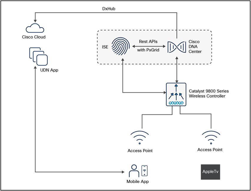
UDN solution topology
The UDN solution provides an easy way to create a virtual segment that allows user to create a private segment to add their devices. Traffic (unicast, non-Layer 3 multicast, or broadcast) to these devices can be seen only by other devices and users in the private segment. This feature also eliminates the security concern where users knowingly or unknowingly take control of devices that belong to other users in a shared environment. As of now, UDN is supported only in Local mode.
● UDN is enabled on the controller, using the policy profile, and the policy configuration is pushed to all the WLANs on a site.
● UDN association is automatically generated by the UDN cloud service and is inherited by all the devices belonging to a user.
● Users can add or modify devices on the UDN assigned to them by using a web portal or a mobile application. Users can also add devices to another UDN if they are invited to join that network.
● The controller is updated with the client or resource information assigned to the UDN.
● Administrators can add endpoints.
● Administrators can allow device access to all users for lobby printers and other common-area devices.
● Administrators can easily troubleshoot issues.
Restrictions for UDN
● A user can be associated to only one UDN.
● Roaming across controllers is not supported.
● This feature is not applicable for the Cisco Mobility Express and Cisco AireOS platforms. Hence, Inter-Release Controller Mobility (IRCM) is not supported.
● UDN is supported only in Local mode on Wave 2 access points and Catalyst 9100 access points.
● UDN is supported only for centrally switched SSIDs.
● UDN is not supported for Flex mode APs.
● UDN is not supported for fabric SSIDs.
● UDN is not supported for guest anchor scenarios.
● Layer 2 and Layer 3 roaming is not supported.
● Layer 3 multicast (except SSDP/UPnP) containment using UDN is not supported; Layer 3 multicast will continue to work as it does today.
Providing employees access to the corporate network and services from a remote environment poses challenges for both the end user and IT operations. For the home-based teleworker, it is critical that access to business services be reliable, consistent, and secure, providing an experience that is as similar as possible to the office in the organization's facility. In addition, the solution must support a wide range of teleworking employees who have varying skill sets, making it critical to have a streamlined and simplified way to implement the teleworker solution.
Cisco Teleworker access points provide secure communications from a controller to an AP at a remote location, seamlessly extending the corporate WLAN over the internet to an employee's residence. The user's experience at the remote location is the same as it would be at the corporate office. Datagram Transport Layer Security (DTLS) encryption between the AP and the controller helps ensure that all communications have the highest level of security. Users may also need access to cloud applications (for example, Microsoft 365, Amazon Web Services, etc.) so it's important to also have direct access to the cloud with the Teleworker AP (split tunneling) option.
The Cisco Teleworker solution is based on the Cisco Office Extend AP (OEAP) feature. It is specifically designed for teleworkers who primarily use wireless devices. The solution consists of the following components:
Cisco WLCs
Cisco WLCs are responsible for systemwide WLAN functions, such as security policies, intrusion prevention, RF management, QoS, and mobility. They work in conjunction with Cisco Teleworker APs to support business-critical wireless applications for teleworkers. Cisco WLCs provide the control, scalability, security, and reliability that network managers need to build a secure, scalable teleworker environment.
To allow users to connect their corporate devices to the organization's on-site wireless network, the Cisco Teleworker solution offers the same wireless SSIDs at the teleworker's home as those that support data and voice inside the organization.
Cisco Teleworker access points
Cisco has dedicated Teleworker APs, such as the Aironet 1810 and 1815T and the Catalyst 9105 Series, but most Cisco APs can run the teleworker/OEAP functionality. Teleworker APs require a centralized WLC, as the AP communicates with the WLC resources. The APs will download its configuration and synchronize its software/firmware image, if required. The AP establishes a secure DTLS connection to the controller to offer remote WLAN connectivity using the same profile as at the corporate office. Secure tunneling allows all traffic to be validated against centralized security policies and minimizes the management overhead associated with home-based firewalls.
Cisco Teleworker APs deliver full 802.11ac and 802.11ax wireless performance and avoid congestion caused by residential devices because they operate simultaneously in the 2.4-GHz and the 5-GHz RF bands. The APs usually connect to a NAT-controlled home-router environment and provide wired and wireless segmentation of home and corporate traffic, which allows for home device connectivity without introducing security risks to corporate policy.
Corporate firewall
The WLC should be placed in a DMZ, and the corporate firewall must allow CAPWAP control and CAPWAP data traffic through the firewall to the WLC. The general configuration of the firewall allows CAPWAP control and CAPWAP management port numbers through the firewall.
Note: The UDP 5246 and 5247 ports need to be open on the firewall for communication between the WLC and the Cisco Teleworker APs.
Design model
For the most flexible and secure deployment of the Cisco Teleworker solution, deploy a dedicated controller using a Catalyst 9800 Series controller or AireOS wireless controller. In the dedicated design model, the controller is directly connected to the internet edge DMZ, and traffic from the internet is terminated in the DMZ rather than on the internal network, while client traffic is still directly connected to the internal network.
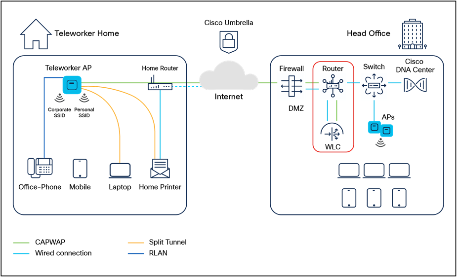
Teleworker solution
A Cisco Wide Area Bonjour domain enables global service routing beyond a single IP gateway for traditional LAN and WLAN networks. In a Cisco Wide Area Bonjour domain, Catalyst LAN switches are deployed in Layer 3 routed mode to act as distributed SDG agents throughout the network. These SDG agents build a TCP-based, stateful, reliable, and lightweight communication channel with a Cisco DNA Center. The Cisco DNA Center must also be configured with the Cisco Wide Area Bonjour application for policy-based global service discovery and distribution.
Wide Area Bonjour, by definition, allows service routing over an IP network without network boundaries. Hence, the core objective of Cisco Wide Area Bonjour is to advertise and browse Bonjour services in a global IP network that is limited to local or remote sites, as required. Typically, the LAN and WLAN IP gateway deployed in SDG Agent mode build the stateful TCP-based unicast connection to the Cisco DNA Center for Wide Area Bonjour service routing.
The fundamentals of service routing are based on the policies defined in Local Area and Wide Area Bonjour domains. The policy defines implicit guidelines to accept, process, and respond to mDNS services on the SDG Agent and the Cisco DNA Center. The service policy carries multiple tuples to distinctly classify and distribute the service provider information along with granular network location. The following figure illustrates an end-to-end reference network model for Cisco Wide Area Bonjour.
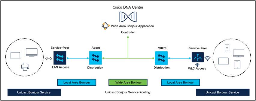
Wide Area Bonjour design
QoS is a key component of traffic transmission efficiency in congested environments. QoS allows applications to be marked to reflect their importance for the business’s operations. In a wired infrastructure, this marking can be used to set different priority levels based on the marking value and perform operations of bandwidth allocation and control based on the application category or marking. In a wireless environment, marking is also used to associate applications to one of the eight user priorities mapped to four access queues. Association to a queue is also used to differentiate the statistical frequency at which an application accesses the wireless medium. Proper marking at the infrastructure level results in optimized downstream traffic, where applications of higher business relevance can receive a statistical transmission advantage and real-time applications can be prioritized over noninteractive applications. The same effect is applicable upstream when the client station marks QoS properly. Apple iOS devices mark QoS as per IETF recommendations.
● The WLC QoS configuration is optimized globally to better support real-time applications.
● Apple iOS devices can send upstream voice traffic without the requirement to perform WMM TSPEC/TCLAS negotiation. The infrastructure will honor the voice marking for these devices.
● You can apply a QoS profile to your Apple iOS 10 devices and decide which applications should receive QoS marking upstream and which should be sent as best effort or background.
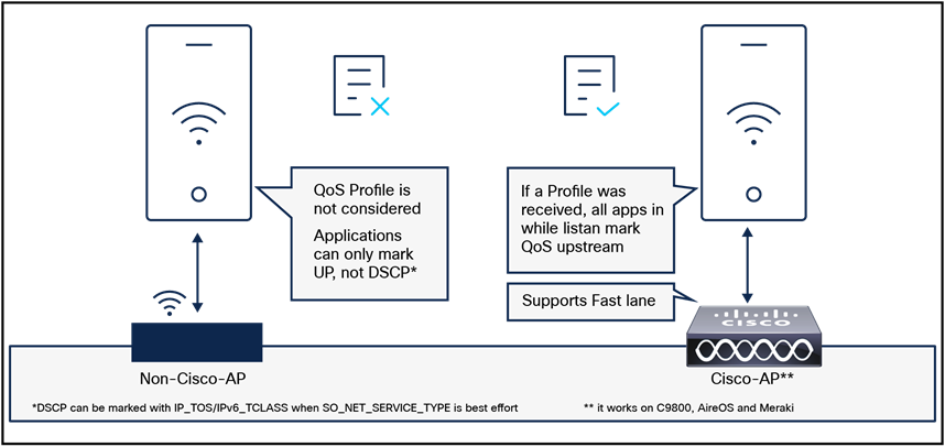
Fastlane
On the Cisco infrastructure side, the Cisco AP will advertise the support for Fastlane as soon as the feature is enabled on the target WLAN.
On the client side, Apple devices running iOS 10 or higher will look for Fastlane support in Information Elements set in the AP beacons and probe responses. The Apple iOS 10 device will also send a specific IE marking its support for Fastlane.
When Fastlane is enabled on a first WLAN, the controller is automatically configured for optimal QoS support for Wi-Fi devices. In particular, the global Platinum profile is configured to allow traffic up to Voice and sets the Unicast Default Priority and the Multicast Default Priority parameters to Best Effort. Per-user bandwidth contracts are disabled on that profile, along with 802.1p. The Platinum profile is then attached to the target WLAN. Wireless CAC (ACM) and Expedited Bandwidth are enabled for the Voice queue for both bands, and the maximum voice bandwidth is set to 50%. A DSCP-to-UP and UP-to-DSCP customized map is configured to map the values recommended by the IETF RFC 8325. DSCP is trusted for upstream traffic. An AutoQoS profile is created that applies the recommended marking to the 32 most well-known applications that typically require differentiated QoS treatment. When AVC is enabled on the target WLAN, this Auto-QoS profile is automatically applied.
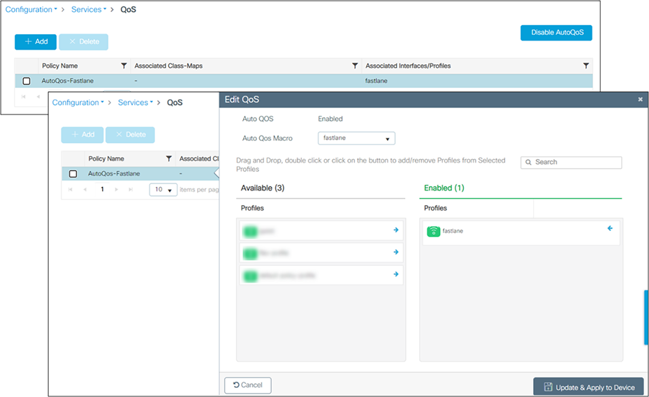
Fastlane Auto QoS
Apple iOS devices can receive a QoS profile (provisioned using standard Apple profile provisioning techniques). This QoS profile lists the applications that can be included in an allowed list. Applications in an allowed list are authorized to apply upstream QoS marking using Apple Service_Type method. Applications that are not in the allowed list do not mark upstream QoS in a Fastlane network. By default, all applications are in an allowed list (without a QoS allowed list, all applications can mark QoS; when an allowed list is deployed, only applications in the allowed list will mark QoS using the Service_Type method; other applications will receive best effort or background QoS treatment). When iOS 10 devices supporting Fastlane, associate to a WLAN that is configured for Fastlane, they apply the QoS profile they previously received. The AP also trusts the iOS 10 QoS marking. Traffic marked as Voice is trusted even if the client does not perform admission control (ADDTS).
When a client is connected to the Fastlane-enabled WLAN, the following service policy will be pushed to the client for both downstream and upstream traffic.
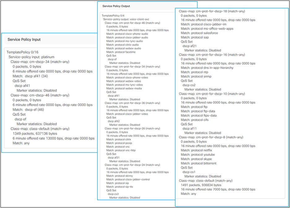
Fastlane service policy
Cisco’s Fastlane+ is a co-developed solution with Apple that significantly improves the experience of any Wi-Fi 6-capable iPhone or iPad connected to a Cisco Wi-Fi 6 network. The existing Fastlane solution has provided an enhanced user experience on iPhones and iPads with optimized roaming and QoS prioritization of time-sensitive VoIP applications through Apple’s Device Management Protocol. Fastlane+ builds upon this success by enhancing Wi-Fi 6’s powerful Orthogonal Frequency Division Multiplexing (OFDMA) scheduler, enabling iOS 14 and above Wi-Fi 6-capable Apple devices to stream high-quality voice and video content efficiently in congested RF environments. Together, Fastlane+ and Fastlane help ensure that users will have the best possible voice and video application experience on Apple devices when connected to a Cisco wireless network.
For Cisco DNA Center, all information about device and client health is typically available from Cisco WLCs. Intelligent Capture provides support for a direct communication link between Cisco DNA Center and APs, so each of the APs can communicate with Cisco DNA Center directly. Using this channel, Cisco DNA Center can receive packet capture data, AP and client statistics, and spectrum data. With the direct communication link between Cisco DNA Center and APs, Intelligent Capture allows you to access data from APs that is not available from wireless controllers.
Capture sessions for a client device
You can run two types of capture sessions for a client device:
Live capture sessions: Live capture sessions can be started immediately and can run for up to three hours for that specific client.
Scheduled capture sessions: Scheduled capture sessions are scheduled for a future time and can run for up to eight hours.
Note: Since scheduled capture and live capture sessions collect the same data, a scheduled capture session that is currently running is equivalent to a live capture session.
Live and scheduled capture sessions allow you to collect data for onboarding events (2-second intervals) and RF statistics charts (5-second samples). This data is displayed in the Client 360 > Intelligent Capture window.
Client capture session limitations
Client capture sessions have the following limitations:
● A total of 16 time slots are allocated for capture sessions (live and scheduled). Each client in a session uses one time slot.
● The maximum number of live capture sessions is 16, so if 16 live capture sessions are running at the same time, no slots are available for scheduled capture sessions.
● The maximum number of concurrent scheduled capture sessions is 12, which always leaves 4 (16 minus 12) available slots for live capture sessions.
● A maximum of 100 packets involved in onboarding events can be captured during the time surrounding the event.
● There is a 3.5 GB limit on the total size of all scheduled onboarding packet files that are residing on Cisco DNA Center. If the limit is exceeded, packet files, starting with the oldest, are removed until the total size falls below the 3.5 GB limit.
Wi-Fi 6 and Wi-Fi 6E Dashboard
The Cisco DNA Center Assurance Wi-Fi 6 and Wi-Fi 6E Dashboard provides a visual representation of your wireless network. The dashboard contains various dashlets that show you the Wi-Fi 6 and Wi-Fi 6E readiness and the efficiency of the Wi-Fi 6 and Wi-Fi 6E networks compared to non-Wi-Fi 6 networks. For more information, see the User Guide https://www-author4.cisco.com/c/en/us/support/cloud-systems-management/dna-center/products-user-guide-list.html.
● Client Distribution by Capability: This dashlet shows all the clients associated and their capability in the wireless network. The inner circle shows the wireless protocol capabilities of all the different clients in the network. Capability here is the ability of wireless clients to associate with Wi-Fi 6 APs, Wi-Fi 6E APs, or non-Wi-Fi 6 APs. The outer arc segment shows how many 802.11ax-capable clients are joined to a Wi-Fi 6 network as well as how many of them are not. The outer segment depicts whether Wi-Fi 6E-capable clients joined a Wi-Fi 6E, Wi-Fi 6, or non-Wi-Fi 6 network based on dashlet status.
● Wi-Fi 6 and Wi-Fi 6E Network Readiness: This dashlet shows all the APs in the network. The inner circle shows the APs that are Wi-Fi 6 APs, Wi-Fi 6E APs, and non-Wi-Fi 6 APs. The outer segment depicts the Wi-Fi 6E APs with the 6-GHz band enabled or Wi-Fi 6 APs with 11ax enabled.
● AP Distribution by Protocol: This dashlet shows the protocols enabled on your APs in real time.
● Wireless Airtime Efficiency: This dashlet compares and displays the airtime efficiency between your Wi-Fi 6 network, Wi-Fi 6E network, and non-Wi-Fi 6 networks for each of the access categories (voice, video, best effort, background). The spectrum is efficiently utilized if the AP radios can send more traffic (successful bytes transmitted to the client) in less airtime (microseconds) than other networks under similar RF conditions.
● Wireless Latency by Client Count: This dashlet compares the wireless latency between your Wi-Fi 6 and non-Wi-Fi6 networks for each of the access categories (voice, video, best effort, background). Wireless latency is measured by the time (microseconds) it takes for a packet to be successfully transmitted from an AP to the client. Hence, AP radios with a higher client count generally have higher latency compared to those with a lower client count under similar RF conditions.
Cisco AI Network Analytics is an application within Cisco DNA Center that leverages the power of machine learning and machine reasoning to provide accurate insights that are specific to your network deployment, which allows you to quickly troubleshoot issues. The following figure and the information that follows describe the Cisco AI Network Analytics architecture:
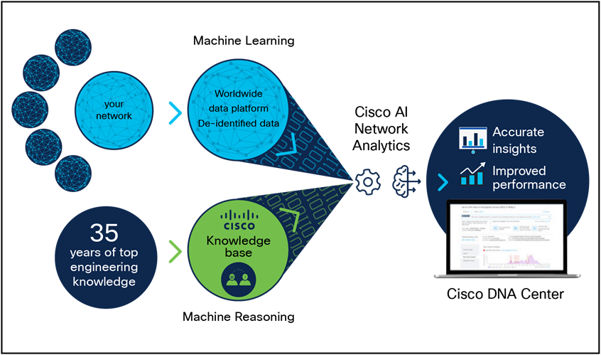
Cisco AI Network Analytics architecture
Cisco AI Network Analytics consists of the following:
● A worldwide cloud-based data platform where machine learning models are built and analyzed for your specific network environment.
● A machine reasoning inference engine that automates human expertise and captures the workflows in a knowledge base repository.
Machine learning
Cisco AI Network Analytics leverages advanced machine learning techniques and an advanced cloud learning platform with deidentified network event data to identify critical issues in your network and provide a rich set of information so that you can quickly troubleshoot issues, know their root causes, identify trends and insights, and obtain relevant comparative perspectives. Cisco AI Network Analytics provides this value using a simple, intuitive, and powerful user interface within Cisco DNA Center that is fully integrated with Cisco DNA Assurance.
The following figure and the information that follows describes the Cisco AI Network Analytics features:
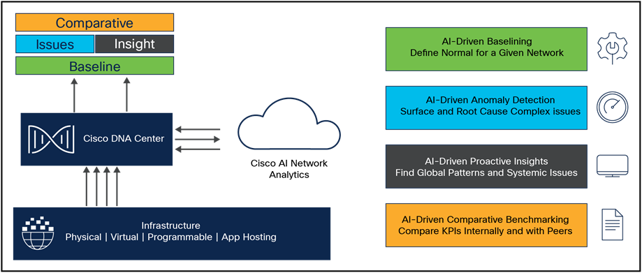
Cisco AI Network Analytics features
Cisco AI Network Analytics provides the following:
● Cloud-based infrastructure: Information on network events is deidentified in Cisco DNA Center and sent through a secure encrypted channel to the Cisco AI Network Analytics cloud-based infrastructure. The Cisco AI Network Analytics cloud runs the machine learning model with the deidentified network event data and brings the issues and overall insights back to Cisco DNA Center.
● Intelligent issue detection and analysis includes:
◦ AI-driven baselining: Baselining is a method used to analyze network dynamics to extract behavioral patterns that help define the "normal" (baseline) behavior for that specific network. The actual network performance is then compared with that baseline.
◦ Cisco AI Network Analytics uses the most advanced machine learning techniques to define the baseline that is relevant to your specific network and sites with the current conditions. With this information, Cisco AI Network Analytics can define what is normal for each network and site at a specific moment and identify the most important issues.
◦ AI-driven anomaly detection: Detect anomalies to determine their root causes and ease troubleshooting. Cisco AI Network Analytics can detect the following types of AI-driven issues:
◦ Connection issues (onboarding issues): Excessive time, excessive failures, excessive DHCP time, excessive DHCP failures, excessive AAA time, excessive AAA failures, excessive association time, and excessive association failures.
◦ Application experience issues: Total radio throughput, media application throughput, cloud application throughput, and social application throughput.
● Trends and insights, including:
◦ AI-driven proactive insights: Determine global patterns (trends) and deviations to provide system-generated insights.
◦ Comparative benchmarking, including:
◦ AI-driven AP comparisons in network heatmaps: Compare all the APs in your network for a given month in a heatmap to spot trends and gain insights.
◦ AI-driven peer comparisons: Determine how your network is performing in comparison to your peer networks for a selected Key Performance Indicator (KPI).
◦ AI-driven site comparisons: Determine how a site (building) is performing compared to another site in your network for a selected KPI.
Machine reasoning
The Machine Reasoning Engine (MRE) is a network automation engine that uses AI to automate complex network operation workflows. It encapsulates human knowledge and expertise into a fully automated inference engine to help you perform complex root cause analysis, detect issues and vulnerabilities, and either manually or automatically perform corrective actions. The MRE is powered by a cloud-hosted knowledge base, built by Cisco networking experts.
AI-Enhanced RRM is the next evolution of Cisco’s award winning RRM. RRM was originally introduced with Cisco AireOS and Aironet in 2005 and has managed the complexities of RF from Wi-Fi 1 through Wi-Fi 6 and now Wi-Fi 6E. RRM has fluidly grown to include innovative algorithms such as FRA and DBS, as well as the traditional algorithms of DCA and TPC.
On a Cisco Catalyst 9800 Series controller, RRM runs as a service. It manages the RF group (the components making up the RF network) based on dynamic measurements between every AP and its neighbor stored in a local database for the entire RF group. At runtime RRM draws on the last 10 minutes of collected data and gently optimizes based on the current network conditions. Cisco RRM has proven to be extremely effective and trustworthy over the years. Configured correctly for the type of RF network coverage desired (capacity vs. coverage), it can adapt to almost any size or deployment density. In Wi-Fi, RF conditions can and do dynamically change with different network loads and numbers of devices and users in the environment, and RRM has measured up well to this task.
Enter Cisco’s AI-Enhanced RRM. AI-Enhanced RRM integrates the power of Artificial Intelligence and Machine Learning (AI/ML) into the reliable and trusted Cisco RRM family of algorithms in the cloud. AI-Enhanced RRM is coordinated through Cisco DNA Center (on-premises appliance) as a service. Existing Cisco Catalyst 9800 RRM sites can be seamlessly transitioned to an intelligent centralized service. As with other Cisco DNA Center services, AI-Enhanced RRM brings a host of new features with it. The Cisco DNA Center RRM Control Center allows administrators to quickly assess the health and performance of the RF coverage from the enterprise level all the way down to a single site or building level.
Cisco AI-Enhanced RRM is different, as it brings the ability to analyze historical dynamic RF data over time. The ability to evaluate complex RF data often comes down to being able to factor in what’s “normal” against the current data. “Normal” can and does vary from site to site based on the numbers and types of users, technology and equipment choices, and architectural design density. Often “normal” is in the mind of the beholder.
After an initial learning period the Cisco AI Analytics Cloud will begin to provide insights into the performance and tuning of the RF network. Insights provide granular guidance on:
● Performance against SLAs
● The effectiveness of present settings/configurations
● The quality of the coverage
Together, the AI-Enhanced RRM algorithms, with the power of the Cisco AI Analytics Cloud and Cisco DNA Center, take Wi-Fi RF management to an unprecedented level that correlates 24x7 observations from the network and the client devices themselves and applies 20+ years of Cisco RF excellence to drive exceptional user experiences into the future.
Enterprise wireless networks are a rapidly growing part of today’s technology. They are becoming more mission-critical each day as new companies migrate to wireless solutions as a means to run their business. As wireless networks grow exponentially, we as a society are becoming more connected than ever before, giving us the ability to solve problems that once seemed complex with simple yet elegant solutions. However, these endless technological possibilities have also triggered a surge of both dependency and the expectation that technology must continue to better every aspect of our daily lives. The IoT has arisen, in part, as a result of these expectations, and Cisco’s state-of-the-art technology known as Application Hosting on Catalyst APs was created to help spearhead this movement.
The Application Hosting on Catalyst Access Points feature provides users with the ability to load third-party containerized Cisco IOx applications directly onto Cisco Catalyst access points and to leverage them as an IoT gateway. Once loaded, the third-party application gains complete access to specific AP software and hardware resources. Depending on the IOx application developed, it can promptly communicate with third-party software through its internal VLAN, or with hardware through its external-facing USB port. A typical business running a Cisco powered wireless infrastructure will have APs deployed throughout all employee-inhabited facilities. Giving third-party vendors the ability to create applications and leverage these access points as IoT gateways has created endless possibilities for the IoT movement.
Prerequisite: Installing the Application Hosting package from Cisco DNA Center
Cisco DNA Center provides the option to download a package called Application Hosting. You can download and install this package on top of the base Cisco DNA Center software.
● To install the Application Hosting package, log in to Cisco DNA Center and open the menu in the top left corner.
● Click System > Software Updates, then click Installed Apps on the left. Scroll down to Automation and you will find the package available for download or installation (Figure 88).
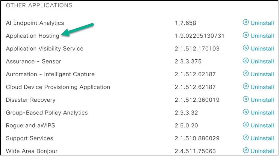
Cisco DNA Center installed software
Cisco Spaces: IoT Services is a platform service within Cisco Spaces that enables you to claim, manage, and monitor IoT devices using Cisco's wireless infrastructure. Cisco Spaces: IoT Services is designed to enable management of IoT devices across vendors, form factors, and technology protocols. Bluetooth Low Energy (BLE) is the first technology available for management using IoT Services.
Cisco Spaces: IoT Services encompasses hardware, software, and partner components to enable the management of devices that support critical business outcomes. Cisco Spaces: IoT Services uses Catalyst 9800 Series controllers, Cisco Spaces: Connector, Cisco Wi-Fi 6 APs, and Cisco Spaces. Cisco Spaces: IoT Services is a next-generation approach to managing complexity in an enterprise IoT environment.

High-level deployment workflow
Using Cisco Spaces: IoT Services, you can perform the following management activities:
● Deploy BLE gateways on supported APs in your network.
● Claim BLE beacons that you acquired from Cisco Spaces: IoT Device Marketplace.
● Configure APs and manage floor beacons.
● Monitor device attributes such as location, telemetry, battery status, and movement status.
Components of Cisco Spaces: IoT Services
The section describes various components that work to complete the Cisco Spaces: IoT Services solution. The Catalyst 9100 access points act as a gateway of communication between Cisco Spaces and the IoT devices. Cisco Spaces: IoT Services can then use a range of common APIs to communicate with edge devices and apps. Cisco Spaces: IoT Services collects data from devices and apps and passes it to Cisco partnered Device Manager websites. The Device Manager websites can leverage these edge-device signals and make the outcome specialized and targeted for each industry.
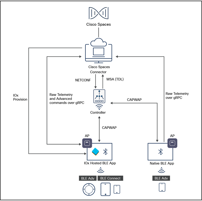
Cisco Spaces network diagram
You can configure access points as gateways in this solution. You can find the list of supported APs in the Compatibility Matrix section. https://www.cisco.com/c/en/us/td/docs/wireless/compatibility/matrix/compatibility-matrix.html#cisco-spaces-compatibility-matrix.
Depending on the type of Cisco AP, you can configure an AP as one of the following types of BLE gateways:
● Base BLE gateway: The base BLE gateway is a type of AP that you can configure in one of two modes, either Transmit mode or Scan mode.
◦ In Transmit mode, the AP can broadcast iBeacon, Eddystone URL, and Eddystone UID profiles.
◦ In Scan mode, the AP can scan the vicinity for other BLE devices. Using gRPC on the AP, the AP sends the scanned data to Cisco Spaces: Connector. The AP can also receive telemetry data from floor beacons. The Cisco Spaces: Connector dashboard decodes and displays this information.
● Advanced BLE gateway: The Advanced BLE gateway is an AP that is installed with an IOx application. Using the installed IOx application, you can configure floor beacons on the Cisco partnered Cisco Spaces: Connector website. As with the base BLE gateway, you can configure this AP in Scan mode or Transmit mode.
The Catalyst 9800 Series wireless controllers combine RF excellence with Cisco IOS XE benefits, and they are available in physical or virtual form factors. This controller is reliable and highly secure. You can manage it using CLI, Web UI, NETCONF, Yang, or Cisco DNA Center.
The controller is the single point for configuring and managing a wireless network and APs. The controller configures and manages APs using the CAPWAP protocol.
The controller receives the BLE configuration from Cisco Spaces over NETCONF and passes the configuration to the AP over CAPWAP. The feedback path from the AP to the wireless controller is through CAPWAP and from the controller to Cisco Spaces through Telemetry Data Language (TDL) telemetry streaming. The gRPC configuration from Cisco Spaces also goes through the controller and from there to the AP.
The configuration sets up the gRPC channel between the AP and Cisco Spaces. The AP sends gRPC channel statistics to the controller, where you can view them.
The AP Power Save feature allows a network administrator to force APs to operate in low-power mode to reduce power consumption.
AP power policy
The AP power policy allows you to define the power budget utilization available for an AP, wherein you can define a set of policies for different interfaces on an AP. You can manage interfaces such as Ethernet interfaces, Wi-Fi radios, USB, and so on, as required.
Use case for AP power policy
You can define a power policy for the available power inputs, such as 802.3af, 802.3at (for multiple levels), DC power, and so on. With tri-radio and quad-radio APs, the power requirement has gone beyond the capability of the 802.3at Power over Ethernet (PoE) mode. Therefore, with the AP power policy, for example, we statically predefine an AP operation when provided with non-802.3bt power (such, as TX power, radio chains, USB port, SFP, and so on).
Power-save mode
The power-save mode enables an AP to switch to a low-power mode when no clients are associated with the AP. For example, when this mode is enabled in workspaces, the AP falls asleep during after-hours, thereby reducing power consumption of the AP throughout the night.
Power-save mode has the following advantages:
● Increases the energy savings per AP: In power-save mode you can reduce AP functions during off-peak hours and save an additional 20% in energy costs compared to the regular idle mode.
● Enables environmentally conscious purchases: Large enterprises and companies track environmental performance as one of their key indices. They have a centralized energy team to monitor their energy efficiency, which magnifies the importance of the power-save feature.
PoE profiles
Fixed PoE profile: The APs negotiate the power that is required from the switches they are connected to. The power required varies from one AP model to another. If an AP is not granted the power it requested, it operates under the power budget. In such conditions, some of the interfaces operate under degraded conditions.
For example, some radios may operate at two spatial streams instead of at four, which they are capable of. The operating conditions for each of the AP interfaces differs from one power level to another. These are referred to as fixed PoE profiles. Fixed PoE profiles are applied when the AP is operating in normal mode, that is, non-power-save mode. When the AP operates in power-save mode, the configured PoE power policies are applied.
PoE power policy: With power policies or profiles, you can configure interfaces that you want to set at certain speeds. With this policy, you can configure a profile of your choice that will be pushed to the AP based on your calendar or timing. For example, in a group of APs on the second floor, push a profile for turning off all APs, except 2.4-GHz radio and Multigigabit Ethernet at 100 megabytes, from 7 p.m. to 7 a.m.
Intuitive workflows: Wireless basic flow
The wireless basic setup uses intent-based workflows to define local and remote sites, create wireless networks for these sites, define policies such as VLAN, ACL,and QoS, and fine-tune RF characteristics. Corresponding policies and tags are created in the back end in accordance with the new configuration model but are transparent to the end user. Access points are assigned to the site and in turn are assigned policy, RF, and site tags.
To access the Basic wireless setup, click the Wireless Setup icon in the top right corner of the dashboard page and select Basic, as shown below.
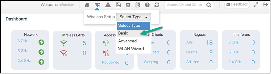
Basic setup wizard
Step 1. Create new site and general site settings
A location is defined as a site either in the campus (local) or across the WAN in a branch (remote) that has a specific set of services, policies, and RF. Select a name, description, and location type (Local or Flex) as well as a client density as Low, Typical, or High. In the flow below, a local site is created with the name SiteA.
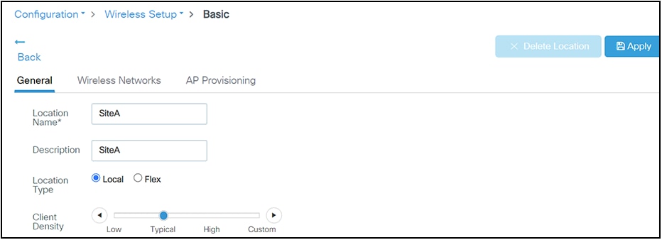
Basic setup wizard – location configuration
Step 2. Create a wireless network and policies within the site
WLANs created as part of the day-0 setup are available to add to this site. These WLANs can be added as is or modified for the policy details that are required for this network in the local site. Alternatively, new SSIDs can be created using the “Define new” link.
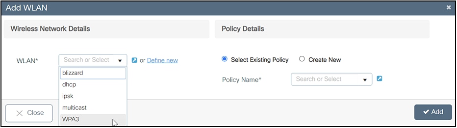
Basic setup wizard – WLAN and policy configuration
Create a remote site
Similarly, selecting “Flex” as the location type enables you to create a remote site. In addition to the fields available for the local site, remote site-specific parameters such as native VLAN ID and local AAA servers can be configured on this page. A globally defined AAA server can be used, or a new server can be added using the “Add New Server” link.
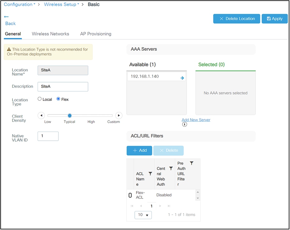
Basic setup wizard – FlexConnect location configuration
On the Wireless Networks tab, the SSID being added to the remote site can be configured as a local switching, local authentication SSID.
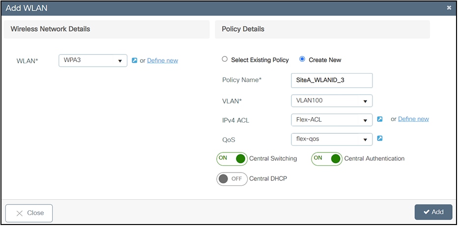
Basic setup wizard – FlexConnect WLAN and policy configuration
In the back end, a custom site tag with a custom Flex profile is defined and associated with this remote site.
Step 3. Provision APs to the site
Once the wireless network and RF characteristics are set up, APs can be added to the local or remote site, either by using static AP MAC address assignment or by assigning already joined APs to a specific location.
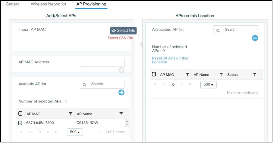
Basic setup wizard – AP provisioning
Policy, site, and RF tags are automatically pushed to the APs upon provisioning.
Intuitive workflows: Wireless advanced flow
To access the Advanced wireless setup, click the Wireless Setup icon in the top right corner of the dashboard page and select Advanced as shown below.
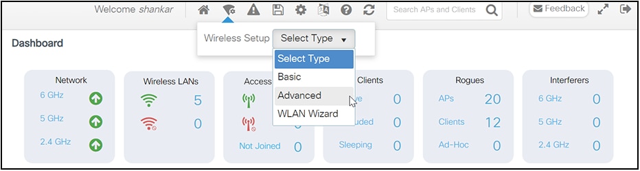
Advanced setup wizard
A guided workflow has been created for easy navigation through the steps required to set up the network using a Catalyst 9800 Series wireless controller.
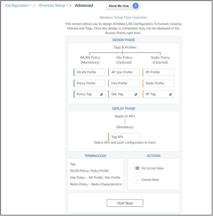
Advanced setup wizard – different phases
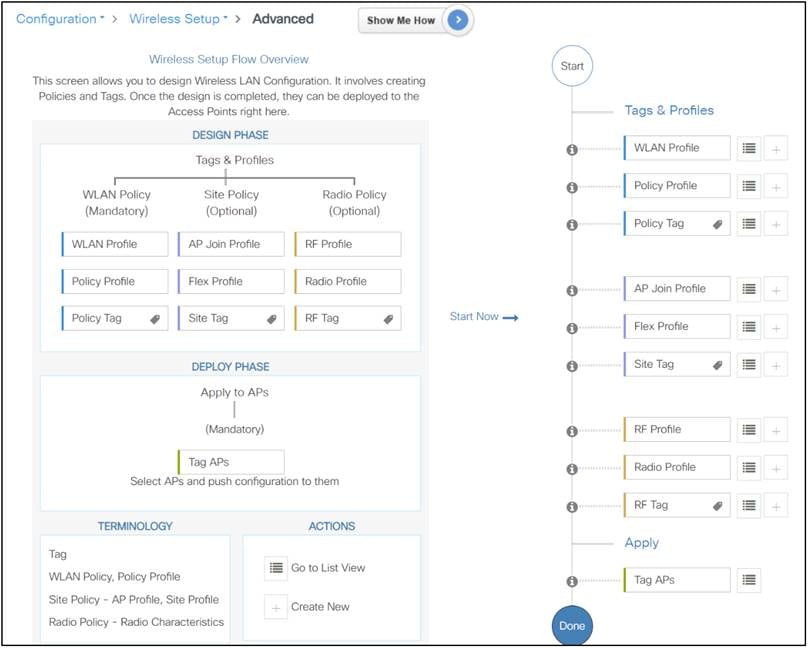
Advanced setup wizard – different phases and tag mapping
The following steps define the logical order of configuration. Note that apart from the WLAN profile, all profiles and tags have default objects associated with them.
Step 1. Create profiles
● Create the required WLAN profiles (SSIDs).
● Create the policy profiles (if non-default needed).
● Create the RF profiles (if non-default needed).
● Create the site profile (if non-default needed).
Step 2. Create tags
● Create the policy tag (if non-default needed) and map the SSIDs created in step 1 to the policy profiles as required.
● Create the RF tag (if non-default needed) and add the RF profiles for 11a and 11b to it
● Create the site tag (if non-default needed) and add the Flex profile (if the site is a remote site) and the AP join profile (most cases will use the default).
Step 3. Associate the tags to APs
If no custom tags are needed, this step is not required, as default tags are associated with the APs.
If the tag to be associated is non-default, associate the tags to the APs.
● Associate the RF tag to the AP or set of APs.
● Associate the policy tag to the AP or set of APs.
● Associate the site tag to the AP or set of APs.
Intuitive workflows: Wireless WLAN wizard
The WLAN wizard will guide you Step by Step to Define a WLAN (SSID) and the related configurations such as the WLAN policy, AAA configuration, ACLs, and URL filters as applicable to the WLAN deployment type selected. At the end you will be able to associate the WLAN to tag(s) and apply the tag to APs.
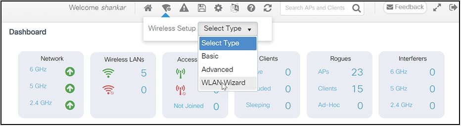
WLAN wizard
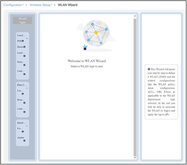
WLAN wizard – configuration flow
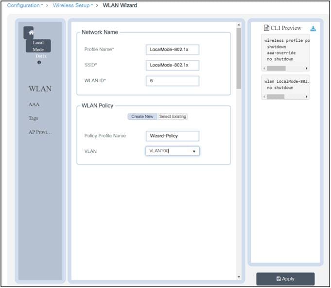
WLAN wizard – WLAN and policy configuration
Whenever an addition to the configuration is made in the WLAN wizard, the equivalent CLI commands will be automatically generated.
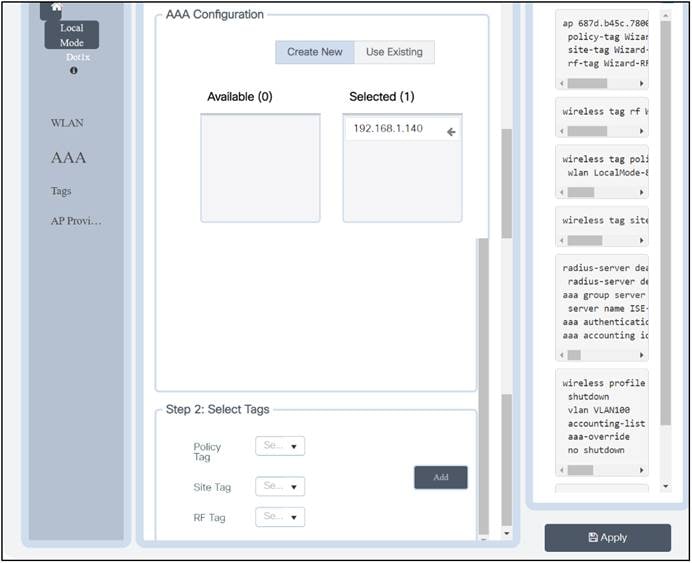
WLAN wizard – full configuration
Once the WLAN wizard workflow is completed, you can view the entire automatically generated CLI commands in the side pane. This preview section provides the option to download the equivalent CLI commands that are created in the workflow for review or can be pasted into the WLC directly to configure it.
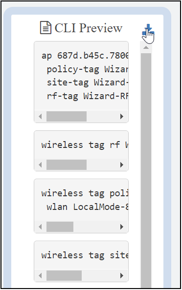
WLAN wizard – CLI preview
Guided assistance: Interactive help
The Catalyst 9800 Series Wireless Controller GUI features an interactive help system that walks you through the GUI and guides you through complex configurations.
You can start the interactive help system in the following ways:
● Hover your cursor over the blue flap in the right-hand corner of a window in the GUI and click Interactive Help.
● Click “Walk Me Through” in the left pane of a window in the GUI.
● Click “Show Me How,” which is displayed in various parts of the GUI. This triggers a specific interactive help that is relevant to the context you are in.
For instance, “Show Me How” in Configure > AAA walks you through the various steps for configuring a RADIUS server. Choose Configuration > Wireless Setup > Advanced and click “Show Me How” to trigger the interactive help that walks you through the steps relating to various kinds of authentication.
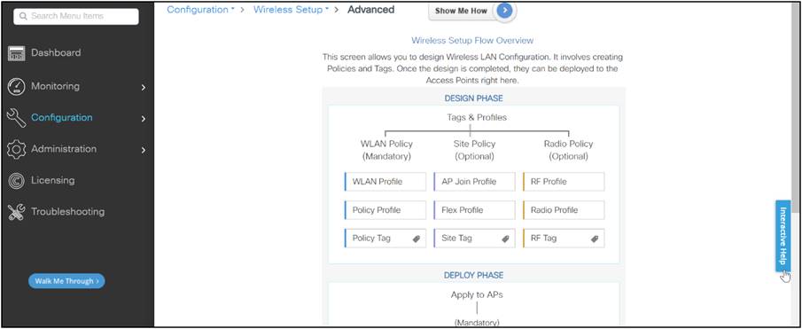
Guided assistance
The following features have an associated interactive help:
● Configuring WLAN
● Configuring AAA
● Configuring FlexConnect authentication
● Configuring 802.1x authentication
● Configuring local web authentication
● Configuring OpenRoaming
● Configuring mesh APs
● Troubleshooting AP join
Flexibility in orchestration: Options to use
Catalyst 9800 configuration management: Prime Infrastructure
For Prime Infrastructure to configure, manage, and monitor the Catalyst 9800 Series WLCs, it needs to be able to access the Catalyst 9800 via CLI, SNMP, and NETCONF. When adding a Catalyst 9800 to Prime Infrastructure, you will need to specify telnet/SSH credentials as well as the SNMP community string, version, etc. Prime Infrastructure uses this information to verify reachability and to inventory the Catalyst 9800 WLC. It will also use SNMP to push configuration templates as well as support traps for AP and client events. However, for Prime Infrastructure to gather AP and client statistics, NETCONF is leveraged. NETCONF is not enabled by default on the Catalyst 9800 WLC and needs to be manually configured.
Communication between the Catalyst 9800 and Prime Infrastructure uses different ports.
● All configuration and templates available in Prime Infrastructure will be pushed via SNMP and CLI. This uses UDP port 161. Operational data for the Catalyst 9800 WLC itself is obtained over SNMP. This uses UDP port 162.
● AP and client operational data leverages streaming telemetry.
● Prime Infrastructure to WLC: TCP port 830 is used by Prime Infrastructure to push the telemetry configuration to Catalyst 9800 devices (using NETCONF).
● WLC to Prime Infrastructure: TCP port 20828 (for Cisco IOS XE Releases 16.10 and 16.11) or 20830 (for Cisco IOS XE Release 16.12,17.x and later).
Note: Keep-alive messages are sent every 5 seconds even when there is no telemetry to report.
Note: In case there is a firewall between Prime Infrastructure and the Catalyst 9800, be sure to open these ports to establish communication.
For more information on managing the Catalyst 9800 with Cisco Prime Infrastructure see Manage Catalyst 9800 Wireless Controller Series with Prime Infrastructure with SNMP V2 and V3 and NetCONF:
Catalyst 9800 configuration management: Cisco DNA Center
Cisco DNA Center is a powerful network controller and management dashboard for secure access to networks and applications. It lets you take charge of your network, optimize your Cisco investment, and lower your IT spending.
Your network is morfe strategic to your business than ever before. You need a network management system that can automate the deployment, connectivity, and lifecycle of your infrastructure and proactively maintain the quality and security of your applications so that your IT staff can focus on networking projects that enhance your core business. You need an intent-based networking controller.
Configuring the Catalyst 9800 Series through Cisco DNA Center has four major steps, as described in the deployment guide listed below:
● The Define the Wireless Network section presents a high-level overview of the campus WLAN that will be designed and deployed through Cisco DNA Center. It consists of an enterprise HA SSO WLC pair, with APs operating in centralized (local) mode, along with a traditional guest anchor controller.
● The Design the Wireless Network section discusses the integration of Cisco DNA Center with Cisco Identity Services Engine (ISE); creation of the site hierarchy, including the importing of floor maps within Cisco DNA Center; configuration of various network services necessary for network operations such as AAA, DNS, DHCP, NTP, SNMP, and Syslog servers; and configuration of wireless settings including WLANs/SSIDs, VLANs, and RF profiles for the WLAN deployment.
● The Deploy the Wireless Network section discusses discovery of the WLCs, managing the software images running on the WLCs, configuring HA SSO redundancy on the WLCs, provisioning the enterprise and guest WLCs within Cisco DNA Center, joining APs to the enterprise WLC HA SSO pair, provisioning the APs within Cisco DNA Center, and positioning the APs on the floor maps within Cisco DNA Center.
● The Operate the Wireless Network section briefly discusses how Cisco DNA Assurance can be used to monitor and troubleshoot the WLAN deployment.
To access this information, see Catalyst 9800 Non-Fabric Deployment Using Cisco DNA Center: https://www.cisco.com/c/dam/en/us/td/docs/solutions/CVD/Campus/Catalyst-9800-Non-Fabric-Deployment-using-Cisco-DNA-Center.pdf.
Catalyst 9800 configuration management: Programmability
The Catalyst 9800 Cisco IOS XE based WLC has several options for programmatic configuration. Traditional methods for configuring the WLC include the CLI and WebUI, but these have now been expanded to include the programmatic interfaces. These programmatic interfaces include NETCONF, RESTCONF, and the gNMI/gRPC protocols. YANG data models define what data is accessible over the programmatic interfaces, and they come in several varieties. Cisco IOS XE features are defined within the native data models, while standard and vendor-agnostic features are defined within the open data models that are mapped to native data models. Either model can be used for many tasks; however, features specific to Cisco IOS XE are available only in the native models.
Models created by Cisco are referred to as native data models since they are specifically created for the devices and software with which they are associated. The native data models provide the most comprehensive and operational coverage for device functionality.
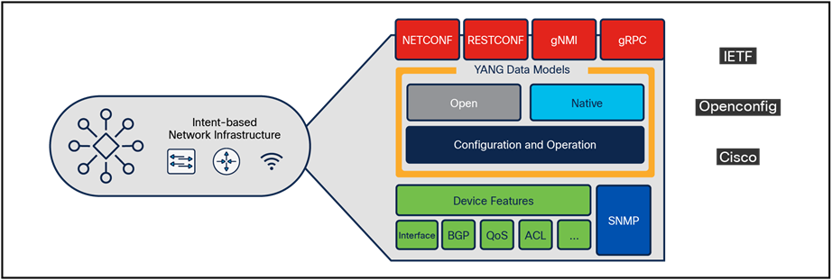
Programmable interfaces and models
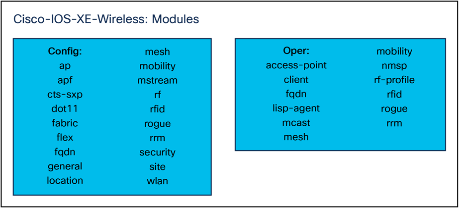
Cisco IOS XE modules
The native models for wireless can be grouped into two main categories: configuration and operational. The configuration modules contain configuration information for the related features, while the operational models provide runtime and operational data about the feature.
For more information on Catalyst 9800 programmability and telemetry, see the Catalyst 9800 Programmability and Telemetry Deployment Guide: https://www.cisco.com/c/en/us/products/collateral/wireless/catalyst-9800-series-wireless-controllers/catalyst-9800-programmability-telemetry-deployment-guide.html.