Migrating Cisco Catalyst 4500-X and 6880/6840-X Series to 9500 Series Switches Guide
Available Languages
Bias-Free Language
The documentation set for this product strives to use bias-free language. For the purposes of this documentation set, bias-free is defined as language that does not imply discrimination based on age, disability, gender, racial identity, ethnic identity, sexual orientation, socioeconomic status, and intersectionality. Exceptions may be present in the documentation due to language that is hardcoded in the user interfaces of the product software, language used based on RFP documentation, or language that is used by a referenced third-party product. Learn more about how Cisco is using Inclusive Language.
The Cisco Catalyst™ 9500 Series Switches are the next generation of enterprise-class switches, built for security, IoT, mobility, and cloud. They leverage the strengths of the Cisco Unified Access® Data Plane (UADP) Application-Specific Integrated Circuit (ASIC) and Cisco Silicon One™ ASIC.
Cisco Catalyst 9500 Series Switches also combine a new onboard x86-based CPU with the open Cisco IOS® XE Software, a converged operating system. Together they deliver model-driven programmability, streaming telemetry, third-party container-based application hosting, application visibility, stronger security, support for higher-bandwidth uplinks, and a more advanced operating system than the Catalyst 4500-X, 6840-X and 6880-X Series offer.
Cisco Catalyst 9500 Series advantages
The Cisco Catalyst 9500 Series is a purpose-built fixed core/aggregation switching portfolio targeted for the enterprise campus, delivering exceptional scales and port densities.
While the 9500 Series switches can be used in traditional 3-tier Layer 2 and Layer 3 based architectures, the diverse features that these platforms support also enable them to be used in fabric-based topologies such as Cisco Software-Defined Access (SD-Access) as border nodes, or in Ethernet VPN (EVPN) or Multiprotocol Label Switching (MPLS) based networks.
In core devices, redundancy and high availability are critical aspects of the design. The Catalyst 9500 Series switches support StackWise® Virtual, along with other high-availability features like Nonstop Forwarding with Stateful Switchover (NSF/SSO), In-Service Software Upgrade (ISSU), and Graceful Insertion and Removal (GIR), along with redundant fan trays and redundant Platinum-rated power supplies.
The Catalyst 9500 Series switches come in two flavors.
● The Catalyst 9500 Series high-performance switches powered by Cisco’s UADP 3.0 ASIC
● The Cisco Catalyst 9500X SVL switches powered by Cisco Silicon One Q200 ASIC architecture
Both are powered by an x86 CPU and provide the options for additional internal and external storage, which enables the device to host containers and run third-party applications and scripts natively within the switch. Table 1 compares the hardware of the 4500-X, 6840-X, and 6880-X Series with the 9500 Series.
Table 1. Hardware comparison
|
|
Catalyst 4500-X |
Catalyst 6840-X |
Catalyst 6880-X |
Catalyst 9500 High Performance |
Catalyst 9500X |
| CPU |
Dual core 1.5 GHz |
Dual core 2.0-GHz x86 |
Dual core 2.0-GHz x86 |
Quad core |
Oct core 2.43-GHz x86 |
| Memory |
4 GB |
4 GB |
4 GB |
16 GB |
32 GB |
| Internal flash |
16 GB |
8 GB |
8 GB |
16 GB |
16 GB |
| External storage |
16 GB |
16 GB
|
16 GB
|
480 GB to |
480 GB to 960 GB |
The system default behaviors on the Cisco Catalyst 9500 Series are very similar to those of the 4500-X Series. For example, interfaces are default in Layer 2 switch port mode, the management interface is in a dedicated Virtual Routing and Forwarding (VRF) instance, and so on. However, there are also some differences:
● Control Plane Policing (CoPP): CoPP is enabled on the Cisco Catalyst 9500 Series, with default policing rates for different classes of traffic. These policing rates are optimized for a typical campus environment. The policing rates can be changed or disabled to meet the requirements of different application environments. On the 4500-X Series, CoPP is not enabled by default, but the system provides a macro to create the different classes. On the 6840-X and 6880-X Series, CoPP is also enabled by default and can be disabled. The 6840-X and 6880-X Series also allow class maps under CoPP to be added, modified, or removed.
● Link-status logging: The logging for link-status changes is on by default with the Cisco Catalyst 9500 Series, and the behavior can be changed per interface. On the 4500-X, 6840-X, and 6880-X Series, the logging for link-status changes is off by default and can be changed globally. See Table 2.
Table 2. Link-status logging comparison
|
|
Catalyst 4500-X |
Catalyst 6840-X and 6880-X |
Catalyst 9500 and 9500X |
| Default |
Off |
Off |
On |
| Configuration |
Per system |
Per system
|
Per interface |
| C4500(config)#no logging event link-status global |
C6800(config)#logging event link-status global |
C9500(config)#int ten 1/0/1 C9500(config-if)#no logging event link-status |
|
| C4500(config)#logging event link-status global |
C6800(config)#no logging event link-status global |
C9500(config-if)#logging event link-status |
The Cisco Catalyst 9500 Series uses the x86 CPU architecture to enable hosting containers and third-party applications. With this change, there are also changes in the ROM Monitor (ROMMON).
Prompts and file systems
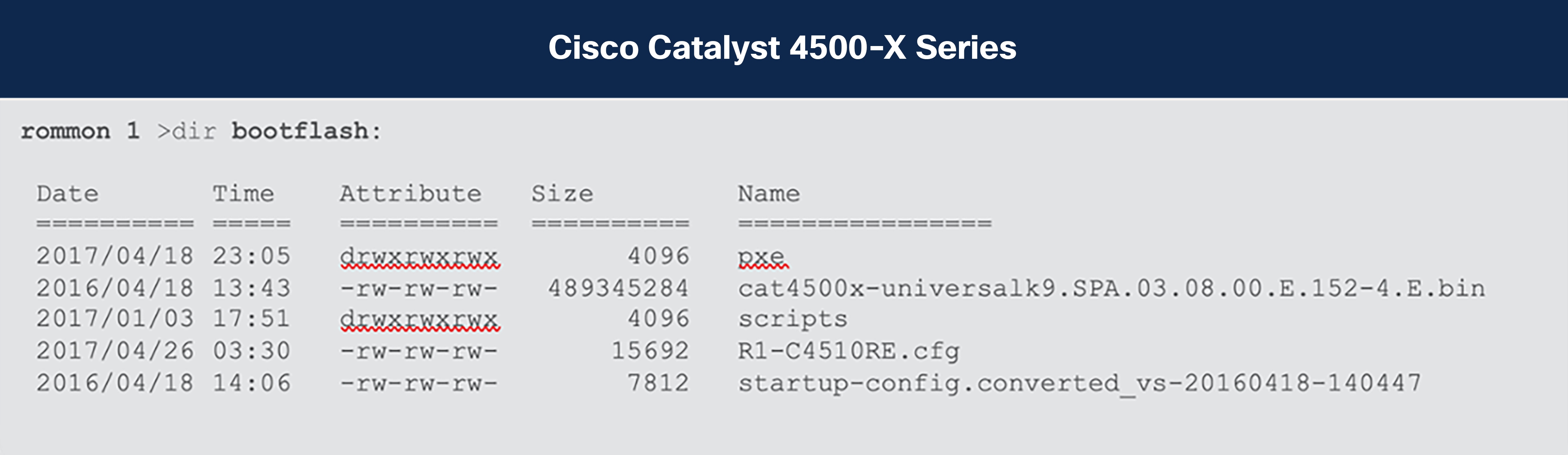
On the Cisco Catalyst 4500-X Series, the prompt is “rommon>” and the “bootflash:” is the memory partition for local storage. On the 6840-X and 6880-X Series, the prompt is “rommon>” and the “bootdisk:” is the memory partition for local storage.
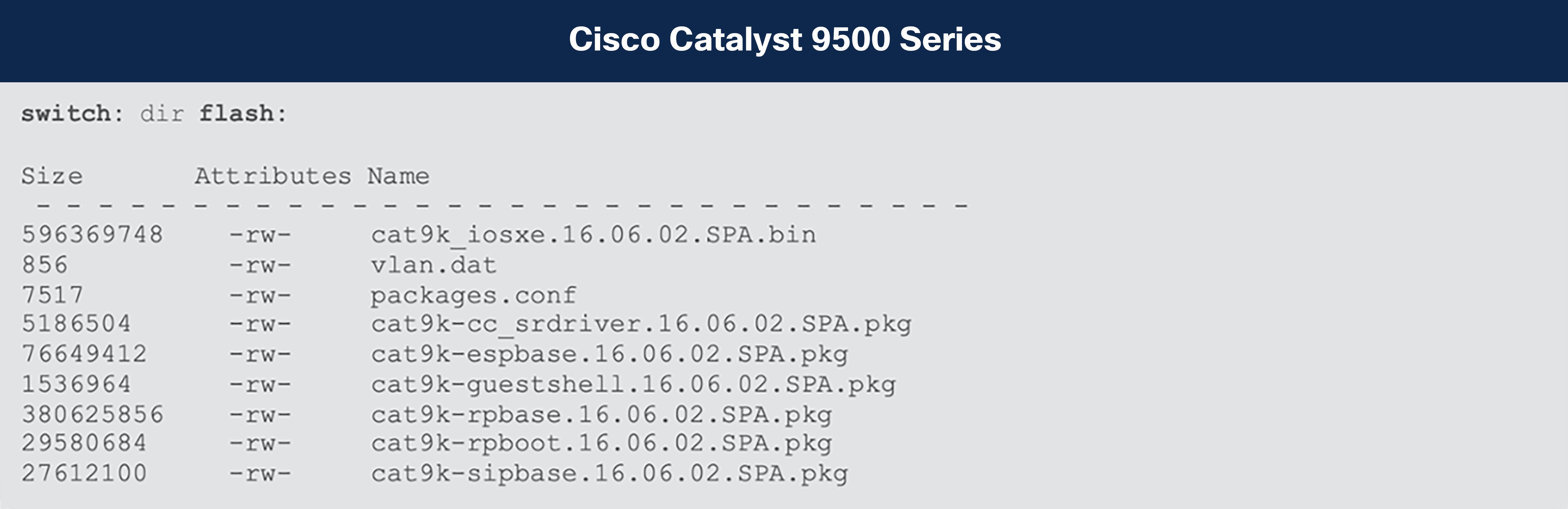
The prompt on the Cisco Catalyst 9500 Series is “switch:” and the “flash:” is the memory partition for local storage. See Table 3.
Table 3. ROMMON outputs
| Cisco Catalyst 6840-X and 6880-X Series |
| rommon 1 > dir bootdisk: File System: FAT32 47959 33554432 -rw- sea_log.dat |
Boot variables
The Cisco Catalyst 4500-X, 6840-X, and 6880-X Series use the traditional “config-register” command in both Cisco IOS and ROMMON to control the booting behavior. The Cisco Catalyst 9500 Series uses a parallel set of commands in Cisco IOS XE that creates the equivalent ROMMON variables. See Table 4.
Table 4. Boot variables
|
|
Catalyst 4500-X |
Catalyst 6840-X and 6880-X |
Catalyst 9500 and 9500X |
|
| Cisco IOS Software |
Confreg 0x???Y Autoboot if Y!=0 |
Confreg 0x???Y Autoboot if Y!=0 |
[no] boot manual |
|
| ROMMON |
Confreg 0x???Y Autoboot if Y!=0 |
Confreg 0x???Y Autoboot if Y!=0 |
MANUAL_BOOT=[no | yes] |
|
Baud rate
With the Cisco Catalyst 9500 Series, the user can set the baud rate in the Cisco IOS XE Command-Line Interface (CLI) or ROMMON. See Table 5.
Table 5. Setting the baud rate
|
|
Catalyst 4500-X |
Catalyst 6840-X and 6880-X |
Catalyst 9500 and 9500X |
| Cisco IOS Software |
Confreg 0x???? or Line con 0 Speed 9600 |
Confreg 0x???? or Line con 0 Speed 9600 |
Line con 0 Speed 9600 |
| ROMMON |
Confreg Use the interactive prompt to set the baud rate |
Confreg Use the interactive prompt to set the baud rate |
BAUD=9600 |
“Break” processing
At the beginning of the bootup process, the user can use Ctrl+C to break out of the booting process and drop the system back into ROMMON if the break sequence is enabled. See Table 6.
Table 6. “Break” processing
|
|
Catalyst 4500-X |
Catalyst 6840-X and 6880-X |
Catalyst 9500 and 9500X |
| Cisco IOS Software |
Confreg 0x???? |
Confreg 0x???? |
[no] boot enable-break |
| ROMMON |
Confreg Use the interactive prompt to set the baud rate |
Confreg Use the interactive prompt to set the baud rate |
ENABLE_BREAK=[no | yes] |
Ignoring the startup configuration
With the Cisco Catalyst 9500 Series, the user can ignore the startup configuration in the Cisco IOS XE CLI or ROMMON. (See Table 7.)
Table 7. Ignoring the startup configuration
|
|
Catalyst 4500-X |
Catalyst 6840-X and 6880-X |
Catalyst 9500 and 9500X |
| Cisco IOS Software |
Confreg 0x8000 or 0x0040 |
Confreg 0x8000 or 0x0040 |
C9500(config)#system ignore startupconfig C9500(config)#no system ignore startupconfig |
| ROMMON |
Confreg Use the interactive prompt to enable/ disable ignore startup configuration |
Confreg Use the interactive prompt to enable/ disable ignore startup configuration |
SWITCH_IGNORE_STARTUP_ CFG=1 |
Interface reference
The Cisco Catalyst 4500-X, 6840-X, and 6880-X Series have two levels of interface numbering: interface <Type><Slot#>/<Port#>.
The 9500 Series has three levels: interface <Type><Switch#>/<Module#>/<Port#>.
For example, Ten Gigabit Ethernet port 1 on slot 1 is referenced as Te1/1 in the 4500-X, 6840-X and 6880-X Series and as Te1/0/1 in the 9500 Series.
In VSS mode on the 4500-X, 6840-X, and 6880-X Series, interface numbering is interface <Type><Switch#>/<Slot#>/<Port#>.
In StackWise Virtual mode on the 9500 Series, interface numbering is the same as the single-chassis default interface:
interface <Type><Switch#>/<Module#>/<Port#>. See Table 8.
Table 8. Interface numbering
|
|
Catalyst 4500-X |
Catalyst 6840-X and 6880-X |
Catalyst 9500 and 9500X |
| Default interfaces |
Te 1/1 |
Te 1/1 |
Te 1/0/1 |
| Uplinks |
Te 2/1 |
– |
– |
| VSS/StackWise Virtual |
Te 1/1/1 for chassis 1 Te 2/1/1 for chassis 2 |
Te 1/1/1 for chassis 1 Te 2/1/1 for chassis 2 |
Te 1/0/1 for chassis 1 Te 2/0/1 for chassis 2 |
On the topic of interfaces, the Catalyst 9500X Series has its uplinks in the middle rather than at the end. This is to help ensure optimal cooling without having to increase the fan speeds.
C9500X-28C8D:
Ports 1-14 and 23-36: 40/100G QSFP ports
Ports 15-22: 40/100/400G QSFP-DD ports
C9500X-60L4D:
Ports 1-30 and 35-64: 10/25/50G SFP ports
Ports 31-34: 40/100/400G QSFP-DD ports
Management interface
With the Cisco Catalyst 9500 Series, “Gig 0/0” is used as the management interface and “Mgmt-vrf” as the management VRF. Please be aware that the VRF name is case sensitive. See Table 9.
Note that the management interface is out of band and would not offer the same features as a fully fledged front panel interface (for example, security such as MACsec, NetFlow operations, etc.).
Table 9. Management interface and VRF
|
|
Catalyst 4500-X |
Catalyst 6840-X and 6880-X |
Catalyst 9500 and 9500X |
| Interface |
FastEthernet1 |
Mgmt0 |
GigabitEthernet0/0 |
| VRF |
mtVrf |
management |
Mgmt-vrf |
For details on the software features supported on the Cisco Catalyst 9500 Series, use the feature navigator on Cisco.com. Some of the features behave differently on the 9500 Series compared to the 4500-X, 6840-X and 6880-X Series. Following are some of these differences.
System Maximum Transmission Unit (MTU)
On the Cisco Catalyst 4500-X Series, the global command “system mtu <1500-1552>” sets the global baby giant MTU for all interfaces. The 4500-X Series also supports per-interface MTU. The per-interface MTU command takes precedence.
On the Cisco Catalyst 6840-X and 6880-X Series, the global command “system jumbo <1500-9216>” sets the global baby giant MTU for all interfaces. The default system jumbo MTU is 9216. The 6500 and 6800 Series also support a per-interface MTU. The per-interface MTU command takes precedence.
With the Cisco Catalyst 9500 Series, the system MTU is a global command that sets the MTU for all the interfaces. See Table 10.
Table 10. Setting the system MTU
|
|
Catalyst 4500-X |
Catalyst 6840-X and 6880-X |
Catalyst 9500 and 9500X |
| “system jumbomtu <>” |
– |
Changes Layer 2 MTU on all interfaces |
– |
| “system mtu” |
Changes Layer 2 MTU on all interfaces |
– |
Changes Layer 2 MTU on all interfaces |
| System jumbomtu/ MTU value |
1500- to 1552 |
1500 to 9216 |
1500 to 9216 |
| Interface-level MTU (layer 2) |
Range “1500-9198” |
Range “1500 to 9216” Takes precedence over system MTU |
Range “1500 to 9216” Takes precedence over system MTU |
The Cisco Catalyst 4500-X, 6840-X, and 6880-X Series support Virtual Switching System (VSS), which combines a pair of switches into a single network element. Similarly, the Cisco Catalyst 9500 Series supports StackWise Virtual, which can provide the same functionality as VSS by extending proven back-panel technology over front-panel network ports (Figure 1).
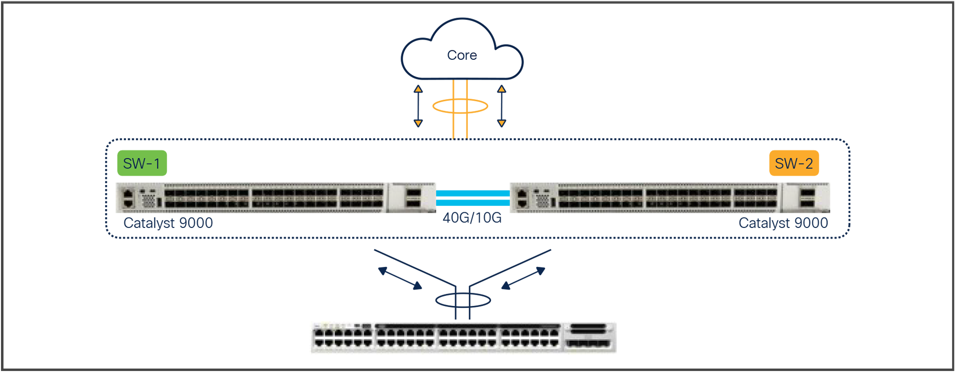
StackWise Virtual
Cisco StackWise Virtual is a network system virtualization technology that pairs two Cisco Catalyst 9000 family switches into one virtual switch. Cisco Catalyst 9000 family switches in a Cisco StackWise Virtual solution simplify operational efficiency with a single control and management plane, scale system bandwidth with a distributed forwarding plane, and assist in building resilient networks using the recommended network design. Cisco StackWise Virtual allows two physical Cisco Catalyst 9500 Series Switches to operate as a single logical virtual switch using a 40 Gigabit or 10 Gigabit Ethernet connection.
A hard requirement for StackWise Virtual is that both participating switches should be the same product ID.
On the Catalyst 9500X switches, StackWise Virtual is supported on the C9500X-28C8D starting with Cisco IOS XE Release 17.10.1 onward and on the C9500X-60L4D with IOS XE Release 17.11.1 onward.
Use the steps below to configure StackWise Virtual.
Step 1: StackWise Virtual domain
| SW-1 |
SW-2 |
| 9500-Dist-1 (config) # stackwise-virtual |
9500-Dist-2 (config) # stackwise-virtual |
| 9500-Dist-1 (config) # domain <1-255> |
9500-Dist-2 (config) # domain <1-255> |
Step 2: StackWise Virtual link
| SW-1 |
SW-2 |
| 9500-Dist-1 (config) # interface range FortyG x/y/z |
9500-Dist-2 (config) # interface range FortyG x/y/z |
| 9500-Dist-1 (config-if) # stackwise-virtual link <1 I 255> |
9500-Dist-2 (config-if) # stackwise-virtual link <1 I 255> |
Step 3: Dual-active detection
| SW-1 |
SW-2 |
| 9500-Dist-1 (config) # interface range TenG x/y/z |
9500-Dist-2 (config) # interface range TenG x/y/z |
| 9500-Dist-1 (config-if) # stackwise-virtual dual-active-detection |
9500-Dist-2 (config-if) # stackwise-virtual dual-active-detection |
Step 4: Save and reload to convert
| SW-1 |
SW-2 |
| 9500-Dist-1 # copy run start |
9500-Dist-1 # copy run start |
| 9500-Dist-1 # reload |
9500-Dist-1 # reload |
Note: On the Silicon One Q200-based Catalyst 9500X switches, the StackWise Virtual and dual-active detection links can be dynamically edited without requiring a system reload.
The initial conversion from a standalone system to a StackWise Virtual system still requires a reload.
For more information, refer to the StackWise Virtual configuration guide for the Cisco Catalyst 9500 Series: https://www.cisco.com/c/en/us/td/docs/switches/lan/catalyst9500/software/release/17-10/configuration_guide/ha/b_1710_ha_9500_cg/configuring_cisco_stackwise_virtual.html.
The Cisco Catalyst 4500-X, 6840-X, and 6880-X Series support IP device tracking (IPDT) for keeping track of connected hosts (association of MAC and IP addresses). In the Cisco Catalyst 9500 Series with the latest Cisco IOS XE release, the new switch integrated security features (SISF)-based IP device-tracking feature acts as a container policy that enables the snooping and device-tracking features available with First Hop Security (FHS) in both IPv4 and IPv6, using IP-agnostic CLI commands. The command “device-tracking upgrade-cli” allows you to migrate the existing IPDT configuration to the new SISF-based device-tracking CLI commands.
Please see Appendix A for detailed information on migrating from the IPDT CLI configuration to the new SISF-based device-tracking CLI configuration.
The Cisco Catalyst 9500 Series and the Cisco Catalyst 4500-X, 6840-X, and 6880-X Series support Flexible NetFlow. Beside the scalability differences, there are a few configuration differences. They are listed in Table 11.
Table 11. Flexible NetFlow differences
|
|
Catalyst 4500-X |
Catalyst 6840-X and 6880-X |
Catalyst 9500 and 9500X) |
| Timestamp |
Use system uptime |
Use system uptime |
Use absolute time (0 is at time 00:00:00 January 1, 1970) |
| NetFlow on port channel |
Configuration under port channel |
Configuration under port channel |
Configuration under Layer 3 port channel and member of Layer 2/Layer 3 port channel |
| Bridged traffic |
Apply the flow monitor to the Layer 2 interface with keyword “layer2-switched” |
Apply the flow monitor to the Layer 2 interface with keyword “layer2-switched” |
Apply the flow monitor to a VLAN |
The NetFlow implementation on the Silicon One Q200-based Catalyst 9500X switches is a software-based implementation. Details of this can be found in the dedicated NetFlow section later in this document.
Switched Port Analyzer (SPAN) filter
The Cisco Catalyst 4500-X, 6840-X, and 6880-X and 9500 Series support SPAN filters. The 4500-X, 6840-X, and 6880-X Series support a filter option of “good/bad,” which isn’t supported on the 9500 Series.
The ASICs that power the Cisco Catalyst 4500-X, 6840-X, and 6880-X and the 9500 Series are different, so there are some differences in QoS behaviors, as described below.
Congestion avoidance
The Cisco Catalyst 4500-X Series supports Dynamic Buffer Limiting (DBL) as a hardware feature, and there are no user-configurable parameters. The Cisco Catalyst 6840-X and 6880-X use Weighted Random Early Detection (WRED), Weighted Round Robin (WRR), and tail drop.
The Cisco Catalyst 9500 Series uses WRED, which randomly discards packets at specified queue thresholds. WRED gives the network operator much more control over the drop behavior.
Table 12 lists other QoS differences between the Cisco Catalyst 4500-X, 6840-X, and 6880-X and the 9500 Series.
Table 12. QoS differences
|
|
Catalyst 4500-X |
Catalyst 6840-X and 6880-X |
Catalyst 9500 High Performance |
Catalyst 9500X |
| Buffer |
32 MB |
192 MB per MUX FPGA |
36 MB |
80 MB with 8 GB expandable |
| Buffer sharing |
All ports shared 32 MB |
Dedicated per port |
All ports shared |
All ports accessible |
| Number of priority queues |
0 or 1 |
2 |
2 |
7 |
| Priority configuration in policy map |
Priority |
Priority level |
Priority level |
Priority level |
| Microflow policing |
Yes |
Yes |
No |
No |
For more information on QoS for the Silicon One Q200-based switches, see the dedicated section later in this document.
Cisco Catalyst 4500-X, 6840-X, and 6880-X Series platform-specific commands
Table 13 lists commands that are specific to the Cisco Catalyst 4500-X, 6840-X, and 6880-X Series and are not available on the 9500 Series.
Table 13. Platform-specific commands
| Catalyst 4500-X |
Catalyst 6840-X and 6880-X |
Catalyst 9500 and 9500X |
| vlan internal allocation policy ascending |
vlan internal allocation policy ascending |
Not applicable |
| diagnostic fpga soft-error recover conservative |
diagnostic fpga soft-error recover conservative |
Not applicable |
| ntp update-calendar |
ntp update-calendar |
clock calendar-valid |
| Ip device tracking |
Ip device tracking |
Please see Appendix A |
| mls <…> |
mls <…> |
Not applicable; the 9500 Series provides hardware-enabled feature by default |
| Auto qos default |
Auto qos default |
Auto qos global compact |
| ip cef load-sharing <…> |
Platform ip cef load-sharing full |
Not applicable |
| Not applicable |
Flow hardware usage notify <…> |
Not applicable |
| Not applicable |
Vlan access-log ratelimit <…> |
Not applicable |
| Ip domain-name |
Ip domain-name |
Ip domain name |
| Ip domain-lookup |
Ip domain-lookup |
Ip domain lookup |
Migrating to the Silicon One Q200-based 9500X switches
The Cisco Silicon One Q200 ASIC brings a host of new capabilities and enhancements to enterprise networks. However, from a feature support perspective, certain features are yet to be ported over from the UADP (and older) platforms.
Note: While most of these features are expected to be supported eventually, there are no defined timelines for this support.
If any of these features are critical to your network operation, it might be prudent to consider the UADP-based Catalyst core 9000 switches if they can satisfy your network requirements. The UADP-based 9500 high-performance switches and the 9600 Series Supervisor Engine 1 will be supported for the near future, and there are no upcoming plans to announce end of sale or end of life (EoS/EoL) of these devices.
The following are the key features not supported as of IOS XE Release 17.12.1:
● Multicast: PIM Dense mode, PIM Bidir, PIM Snooping, and MVPN
● MPLS: VPLS, EoMPLS over Tunnels/port-channels, and Traffic Engineering FRR
● Layer 3 forwarding: NAT/PAT, many advanced PBR features and WCCP
● Layer 2 forwarding: REP, private VLANs, Flex Links, and Bonjour support
● Security: PACL and VACL, FQDN and reflexive ACLs, and RadSec
Note: This is not an exhaustive list. Please validate with the Cisco Feature Navigator for information on support of specific features. When in doubt, please check with your accounts team to determine whether your existing switch configuration (Catalyst 6000 or UADP-based Catalyst 9000) can be ported to a Silicon One Q200-based switch without any feature compatibility and scale limits.
Best practices and caveats when migrating to the Catalyst 9500X
Transitioning to the Cisco Silicon One Q200 represents a significant leap forward in network infrastructure capabilities. The following sections delve into the best practices and key “gotchas” to be aware of during the upgrade process. The objective is to focus on the key features and configurations that are known to require some input during the update process.
We will go over each feature in a separate section below.
● Quality of service (QoS)
● Access control sists (ACLs)
● Flexible NetFlow (FNF)
Quality of service (QoS)
In a first for campus switches, the Cisco Silicon One Q200-based switching platforms use a Virtual output Queueing (VoQ) model. The ASIC comes with a new forwarding model, with QoS closely tied into the capabilities defined by the ASIC, requiring a redesign of the old configuration.
The major difference between the QoS models lies in how the traffic is differentiated and prioritized internally within the switch. The UADP-based Catalyst 9000 switches, as well as older-generation Catalyst 2000, 3000, 4000, and 6000 platforms, all differentiate traffic on the basis of predefined fields available in the IP or the Layer 2 packet header (for example, using a DSCP tag on the Layer 3 packet header). If we cannot or don’t want to use those details in the packet header, we leverage other tools like ACLs or VLANs to first “tag” the packet at ingress, using a qos-group, and calling the same qos-group in the egress.
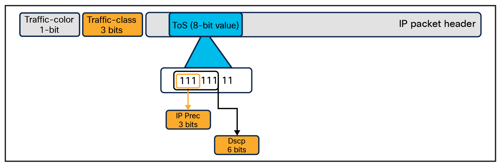
The Silicon One Q200 QoS implementation is different in that we do not use the predefined field already present in the header, but we append two tags to the packet when it enters the switch and remove them when the packet exits the switch. The two tags in question are:
● Traffic-class
● Traffic-color
Tags appended to the header on ingress
Traffic class
Traffic-class is a 3-bit field used by the switch to determine the traffic priority. The values range from 0 to 7. The higher the value, the higher the priority of the traffic. There are two hard predefined settings within the switch that cannot be changed or disabled:
● Traffic class 7 is a strict priority queue with priority level 1 (highest priority).
● Traffic class 0 is the class default, and any untagged traffic automatically gets sent here. This queue is always a normal queue and cannot be configured as a strict priority queue.
At ingress, the incoming traffic must be classified (using Differentiated Services Code Point [DSCP], class of service [CoS], IP precedence, ACLs, or VLANs) into the corresponding traffic classes. Any traffic not matching these classifications will be assigned to traffic class 0.
At egress, we perform queueing and shaping operations based on the traffic class.
Note: Directly configuring DSCP, CoS, IP precedence, ACLs, or VLANs at the egress for queueing will not work, as it will use the default mapping of DSCP/CoS to traffic class instead.
Traffic color
Traffic-color is a 1-bit field (with a value of either 0 or 1) that is used by congestion management algorithms (weighted tail drop [WTD] and weighted random early detection [WRED]) to prioritize traffic within a queue in the event of congestion. All traffic, without exception, is colored green (value of 0) by default. Any traffic-color change to yellow (value of 1) must be explicitly performed via configuration at ingress. The traffic color can be set using the command below.
Set discard-class <0-1>
Note: Trying to perform any congestion management on the egress policy will not work unless the traffic is colored at egress. Congestion management based on packet tags like DSCP or CoS is not supported.
Configuration migration considerations
Let’s examine a 2P2Q configuration using the UADP ASIC as a base. An example configuration would look something like the following:
class-map match-any VOICE-PQ1
match dscp ef
class-map match-any VIDEO-PQ2
match dscp 24
class-map match-any USER-TRAFFIC
match dscp af31 af32 af33
policy-map CAMPUS_EGRESS_POLICY
class VOICE-PQ1
priority level 1 percent 10
class VIDEO-PQ2
priority level 2 percent 20
class USER-TRAFFIC
bandwidth remaining percent 65
random-detect dscp-based
random-detect dscp af31 70 100
random-detect dscp af32 60 80
random-detect dscp af33 50 70
class class-default
bandwidth remaining percent 35
Interface gig1/0/1
service-policy output CAMPUS_EGRESS_POLICY
Let’s ignore the WRED configuration for now and just focus on the queue configurations, translating those to equivalent Silicon One configuration. There are some considerations here:
● Traffic class 7 is a strict priority queue set to level 1. This cannot be changed or disabled.
● The UADP performs the queueing based on the DSCP tags here. On the Silicon One, we must map the DSCP tags to the corresponding traffic class at the ingress and map the traffic class to the queueing operations at the egress.
This requires two separate policies, one at the ingress and one at the egress. Again, ignoring the WRED configurations for now, the “translated” configurations would look like this.
Starting with the INGRESS policy-map (mapping the DSCP to the traffic class):
class-map match-any VOICE-PQ1
match dscp ef
class-map match-any VIDEO-PQ2
match dscp 24
class-map match-any USER-TRAFFIC
match dscp af31 af32 af33
policy-map CAMPUS_INGRESS_POLICY
class VOICE-PQ1
set traffic-class 7
class VIDEO-PQ2
set traffic class 6
class USER-TRAFFIC
set traffic class 5
Interface gig1/0/1
service-policy input CAMPUS_INGRESS_POLICY
Next the EGRESS policy map (queueing based on the traffic class):
class-map match-any tc7
match traffic-class 7
class-map match-any tc6
match traffic-class 6
class-map match-any tc5
match traffic-class 5
policy-map CAMPUS_EGRESS_POLICY
class tc7
priority level 1
class tc6
priority level 2
class tc5
bandwidth remaining percent 65
class class-default
bandwidth remaining percent 35
Interface gig1/0/3
service-policy output CAMPUS_EGRESS_POLICY
The next step would be to migrate the WRED configurations as well. This requires some additional configurations, as the Silicon One Q200 does WRED based on the traffic color and not based on DSCP. Again, there are some considerations here:
● Coloring of the packet must be done at INGRESS.
● Traffic color can either be 0 (green) or 1 (yellow). So we can have a total of two thresholds vs. the three thresholds (one each for af31, af32, and af33) we configured on the UADP switch.
Editing the configuration with these considerations, we get the following “translated” configuration:
Starting with the INGRESS policy map (mapping the DSCP to the traffic class and coloring the traffic):
class-map match-any VOICE-PQ1
match dscp ef
class-map match-any VIDEO-PQ2
match dscp 24
class-map match-any USER-TRAFFIC-GREEN
match dscp af31
class-map match-any USER-TRAFFIC-YELLOW
match dscp af32 af33
policy-map CAMPUS_INGRESS_POLICY
class VOICE-PQ1
set traffic-class 7
class VIDEO-PQ2
set traffic class 6
class USER-TRAFFIC-GREEN
set traffic class 5
class USER-TRAFFIC-YELLOW
set traffic class 5
set discard-class 1
Interface gig1/0/1
service-policy input CAMPUS_INGRESS_POLICY
Next the EGRESS policy map (queueing based on the traffic class and performing WRED based on the traffic color):
class-map match-any tc7
match traffic-class 7
class-map match-any tc6
match traffic-class 6
class-map match-any tc5
match traffic-class 5
policy-map CAMPUS_EGRESS_POLICY
class tc7
priority level 1
class tc6
priority level 2
class tc5
bandwidth remaining percent 65
random-detect discard-class-based
random-detect discard-class 0 percent 80 100
random-detect discard-class 1 percent 50 70
class class-default
bandwidth remaining percent 35
Interface gig1/0/1
service-policy output CAMPUS_EGRESS_POLICY
For more details on QoS architecture and configuration, refer to the QoS white paper for the Silicon One Q200 platforms. You can find the link in the references section later in this document.
Access Control Lists (ACLs)
From a security perspective, ACLs provide a granular method for network administrators to control traffic going into and out of specific nodes in the network. The ACLs are stored in a specialized type of memory called the TCAM (ternary content-addressable memory). This allows for rapid searches for specific fields. However, the space available on the TCAM is finite, and storing a large number of entries requires optimization to make the best use of the space available.
The Silicon One Q200 has a TCAM size of 8000 entries on the default Switch Database Management (SDM) template. In comparison, the UADP has a total space of 54,000 entries using customization SDM templates.
Another consideration is the total number of unique named ACLs (regardless of whether it’s an IP ACL, object group ACL (OG-ACL), or security group ACL [SG-ACL]) in egress and ingress. We can have a total of:
● 126 unique named ACLs (labels) applied in the ingress direction
● 16 unique named ACLs (labels) applied in the egress direction
Object group ACLs
For traditional ACLs, we can leverage the 8000 entries in the TCAM space. However, for larger entries, migrating from a traditional IP ACL to an OG-ACL or SG-ACL would be more beneficial.
OG-ACLs leverage object groups (a collection of similar “objects” like network addresses, port numbers, and protocols) and perform permit or deny operations on them. The advantage of using OG-ACLs and SG-ACLs is that the contents in the object group or security group are expanded to a different field (the CEM, or Central Exact Match), and only the permit and deny statements are programmed into the TCAM space. The CEM space is leveraged to learn the IPv4 and IPv6 routes, and in terms of scale, the Silicon One Q200 supports a sizable number of routes, up to 2 million IPv4 or 1 million IPv6 routes.
Let’s look at an example to understand this better. Below is an example of an ACL calling on an object group.
ip access-list extended SampleACL
permit ip object-group TestGroup any
deny ip any any (implicit)
!
Expanding the object group shows us that it is composed of 10,000 unique entries.
object-group network TestGroup
host 10.5.64.140
host 10.5.64.86
host 10.5.75.124
10.10.170.32 255.255.255.224
10.179.252.0 255.255.252.0
10.5.200.240 255.255.255.240
10.53.199.0 255.255.255.0
10.56.100.224 255.255.255.240
... Truncated (10,000 entries)
host 10.56.223.56
When we apply this OG-ACL to an interface on a UADP-based Catalyst 9000 switch, the contents of the OG-ACL are expanded and programmed to the TCAM space (up to 54,000 entries). However, when we use the same ACL on a Catalyst 9000 switch based on the Silicon One Q200, the contents of the object group are expanded to the CEM table, and only the permit and deny (implicit) is programmed in the TCAM space. So in terms of utilization,
● 10,000 entries are consumed from the 2 million CEM field and
● 2 entries are consumed from the 8000 TCAM field
In this way, we can program large ACLs into the Silicon One Q200-based core Catalyst 9000 switch by leveraging OG-ACLs or SG-ACLs.
Configuration migration considerations
If migrating from a Catalyst 6000 or 9000 switch, we need to consider the following:
● The total number of Access Control Entries (ACEs) in IP ACLs. If fewer than 8000, we can program it as is. But if more than 8000, conversion to OG-ACL or SG-ACL is mandated.
● The number of ACLs applied in the ingress and egress directions. While ingress has a good number of labels (126), it’s easy to exhaust the egress labels. So if the source configuration has many egress ACLs, redesign of the ACL to be applied in the ingress direction is required.
Flexible NetFlow (FNF)
The Silicon One Q200 supports a software-based Flexible NetFlow that uses flows to provide statistics for accounting, network monitoring, and network planning.
A flow is a unidirectional stream of packets that arrives on a source interface and has the same values for the keys. A key is an identified value for a field within the packet. You create a flow using a flow record to define the unique keys for your flow.
NetFlow on the Silicon One Q200
The following are the key differences in the NetFlow implementation on the Silicon One Q200-based Catalyst 9000 switches compared to the UADP-based Catalyst 9000 switches as well as the Catalyst 6000 Series switches:
● The NetFlow is software based – in other words, the packets are sent to the CPU for parsing and there is no dedicated hardware in the ASIC.
● The NetFlow is a sampled implementation – in other words, not every packet across the system is inspected; inspection occurs for only one packet for every N packets, where N is the sample size configured.
● The NetFlow operations can be applied only in the ingress direction. There is no support for NetFlow on the egress direction.
The Catalyst 9500X and Catalyst 9600 Supervisor Engine 2 have an 8-core CPU powering the system. One of these eight cores is explicitly reserved for NetFlow operations, along with a separate IOS XE processing thread. Having a dedicated CPU provides the following benefits:
● Dedicated CPU resources for NetFlow operations: There is no CoPP or other process that can hinder and block NetFlow operations or packets.
● Isolated CPU for NetFlow: Even if NetFlow causes the CPU to spike up, normal management operations on the switch will continue as expected, as only the NetFlow core and operations will be impacted.
The cache size is 2 million.
Here is an example of random sampling: For N = 1000, one packet is selected at random and sent to the CPU for parsing. Information from the header of the packet is inspected, and keys are updated and exported out.
The only supported sampler method is true random sampling. This means that packets are selected at random based on the sample size regardless of flow. Deterministic flow-based sampling is not supported.
Note: This means that, due to the nature of randomness, all the flows are not captured immediately on enabling NetFlow, as packets belonging to that flow might simply not have been sent to the CPU. Over a period, due to the nature of randomness, the exporter will get details on the flow.
Sample size
The recommended sample size is 1000. This recommendation is based on the typical load one can expect from a switch that is handling terabytes of traffic across multiple 100- to 400-Gbps links at any given time. If more aggressive samples are required, the load on the CPU will increase correspondingly as more packets are sent to the CPU for parsing.
Aggressive samples can be used when the rate of traffic is lower than the line rate supported on the devices. We recommend keeping an eye on the CPU load while tweaking the sample, as configuring very aggressive values can quickly overwhelm the dedicated CPU, causing NetFlow operations to break.
We support a sample of up to 1:2, as in 1 in every 2 packets are parsed to the CPU for processing.
Transport security (encryption)
In a hybrid network, transport security is a critical piece to ensure end-to-end security. The new Catalyst 9500X switches support WAN-MACsec in addition to MACsec. These help ensure that traffic is encrypted regardless of the destination of the packet. Within the same network, MACsec helps with the encryption. As the packet leaves the network, we can leverage WAN-MACsec for encryption across the WAN boundary. WAN-MACsec will operate at Layer 2 and at line speed across all the ports.
In terms of support, WAN-MACsec is supported only on Silicon One Q200-based devices, which include the C9500X-60L4D and C9500X-8C8D.
Note that WAN-MACsec requires an additional C9000 HSEC K9 license. The license must be activated on the system to configure these features.
The Cisco Catalyst 9500 Series is the industry’s first purpose-built 40/100/400-Gbps fixed-core/aggregation enterprise switching platform. It is the new generation of fixed core/aggregation platforms and provides many additional capabilities. It is well suited for enterprises looking to migrate from their existing Cisco Catalyst 4500-X, 6840-X, and 6880-X Series deployments.
The Cisco Catalyst 9500 Series Switches are powered either by the UADP or the Silicon One Q200 ASIC. These are two separate switch lines with different feature sets catering to two different use cases. These devices are meant to coexist with each other and not compete. Please consider the use cases as well as feature and scale support when considering which model of the Catalyst 9500 Series to migrate to.
UADP QoS white paper:
https://www.cisco.com/c/en/us/products/collateral/switches/catalyst-9000/white-paper-c11-742388.html#HierarchicalQoS.
Silicon One Q200 white paper:
https://www.cisco.com/c/en/us/products/collateral/switches/catalyst-9500-series-switches/catalyst-9500x-9600x-qos-q200-wp.html.
Catalyst 9500 data sheet:
https://www.cisco.com/c/en/us/products/collateral/switches/catalyst-9500-series-switches/nb-06-cat9500-ser-data-sheet-cte-en.html.
Catalyst 9600 data sheet:
https://www.cisco.com/c/en/us/products/collateral/switches/catalyst-9600-series-switches/nb-06-cat9600-series-data-sheet-cte-en.html.
Catalyst 9500 architecture white papers:
https://www.cisco.com/c/en/us/products/collateral/switches/catalyst-9500-series-switches/nb-06-cat9500-architecture-cte-en.html.
Catalyst 9600 architecture white papers:
https://www.cisco.com/c/en/us/products/collateral/switches/catalyst-9600-series-switches/nb-06-cat9600-architecture-cte-en.html.
If your device has no legacy IP device tracking or IPv6 snooping configurations, you can use only the new SISF-based device-tracking commands for all your future configurations. The legacy IPDT commands and IPv6 snooping commands are not available. For details on SISF configuration, please refer to the configuration guide.
IPDT, IPv6 snooping, and device-tracking CLI compatibility
Table 14 displays the new SISF-based device-tracking commands and the corresponding IPDT and IPv6 snooping commands.
Table 14. Device-tracking and corresponding IPDT and IPv6 snooping commands
| Feature |
Catalyst 4500-X, 6840-X, and 6880-X |
Catalyst 9500 |
| IP device tracking (IPDT) |
IPv6 snooping |
SISF-based device tracking |
| IP device tracking probe count |
Not supported |
Not supported |
| IP device tracking probe delay |
IPv6 neighbor binding reachable-lifetime |
Device-tracking policy reachable-lifetime |
| IP device tracking probe interval |
IPv6 snooping tracking retry-interval |
Device-tracking policy retry-interval |
| IP device tracking probe use-svi |
Accepted and interpreted as IP device tracking probe auto-source override |
Accepted and interpreted as IP device tracking auto-source override |
| IP device tracking probe auto-source fallback |
Not supported |
Not supported |
| IP device tracking probe auto-source override |
Not supported |
Not supported |
| IP device tracking tracebuffer |
Not supported |
Not supported |
| IP device tracking maximum |
IPv6 snooping policy <name> limit |
Device-tracking snooping policy <name> limit |
| IP device tracking probe count |
Not supported |
Not supported |
| IP device tracking probe interval |
Not supported |
Not supported |
| Clear IP device tracking all |
Not supported |
Not supported |