Cisco Silicon One QoS White Paper
Available Languages
Bias-Free Language
The documentation set for this product strives to use bias-free language. For the purposes of this documentation set, bias-free is defined as language that does not imply discrimination based on age, disability, gender, racial identity, ethnic identity, sexual orientation, socioeconomic status, and intersectionality. Exceptions may be present in the documentation due to language that is hardcoded in the user interfaces of the product software, language used based on RFP documentation, or language that is used by a referenced third-party product. Learn more about how Cisco is using Inclusive Language.
This document describes the Quality-of-Service (QoS) and queuing architecture of the Cisco Silicon One™ - based Cisco Catalyst 9000 switching platforms.
In a first for campus switches, the Cisco Silicon One based switching platforms use a Virtual output Queueing (VoQ) model. This document explains the advantages and features of the VoQ model and the various supported QoS actions such as policing, marking, queueing, and scheduling. It then looks at the new dual buffering system, new to the Cisco Silicon One powered switches, and congestion management tools and techniques.
QoS use cases
Enterprise networks must provide end-to-end QoS solutions across the various platforms that span the network. Providing solutions for heterogeneous platforms often requires taking a different QoS configuration approach for each technology. As enterprise networks carry more complex, mission-critical applications, and experience increased traffic from web multimedia applications, QoS serves to prioritize this traffic to ensure that each application gets the service it requires.
Networks must also handle increasingly complex business applications. QoS lets the network handle the difficult task of differentiating and using the interdevice links in the most efficient way for business applications.
QoS helps a network provide guaranteed and predictable services to selected network traffic by adding the following techniques:
● Scheduling to support guaranteed bandwidth
● Reducing loss characteristics for specified traffic
● Avoiding and managing network congestion
● Shaping network traffic to manage bursty applications
● Setting traffic priorities across the network
Using the above techniques to implement QoS in your network has the following advantages:
● Control over resources such as bandwidth, rate-limiting, and so on. For example, you can limit bandwidth consumed over a link by FTP transfers or give priority to traffic accessing an important database.
● Coexistence of mission-critical applications:
◦ Bandwidth and minimum delays required by time-sensitive multimedia and voice applications are available.
◦ Other applications using the link, such as FTP, email, HTTP, or transactions, get their fair level of service without interfering with mission-critical traffic such as voice.
Moreover, by implementing QoS features in your network, you put into place the foundation for a future fully integrated network and use efficient techniques to manage congestion.
The contents of this document apply to all switching devices running on the Cisco Silicon One ASIC. As of this moment, this document applies to the following platforms:
1. Cisco Catalyst™ 9500X Series Switches (C9500X-28C8D and C9500X-60L4D) – Powered by the Silicon One Q200 ASIC
● Cisco Catalyst 9600X Series Supervisor Engine 2 L – Powered by the Silicon One Q200 ASIC
● Cisco C9610 Supervisor Engine 3/3XL – Powered by the Silicon One K100/E100 ASIC
● Cisco C9350 Series Smart Switches – Powered by the Silicon One A100 ASIC
Note: If you have a switch powered by the Unified Access Data Plane (UADP) family of ASICs, the QoS structure explained here does not apply. You can instead refer to the link below for a white paper describing the QoS operations on the UADP ASIC.
https://www.cisco.com/c/en/us/products/collateral/switches/catalyst-9000/white-paper-c11-742388.html
Congestion and head-of-line blocking
Congestion occurs when the destination port cannot transmit all packets, and some packets are then dropped or delayed for longer than expected. Figure 1 illustrates the two types of congestion that require QoS and queuing.
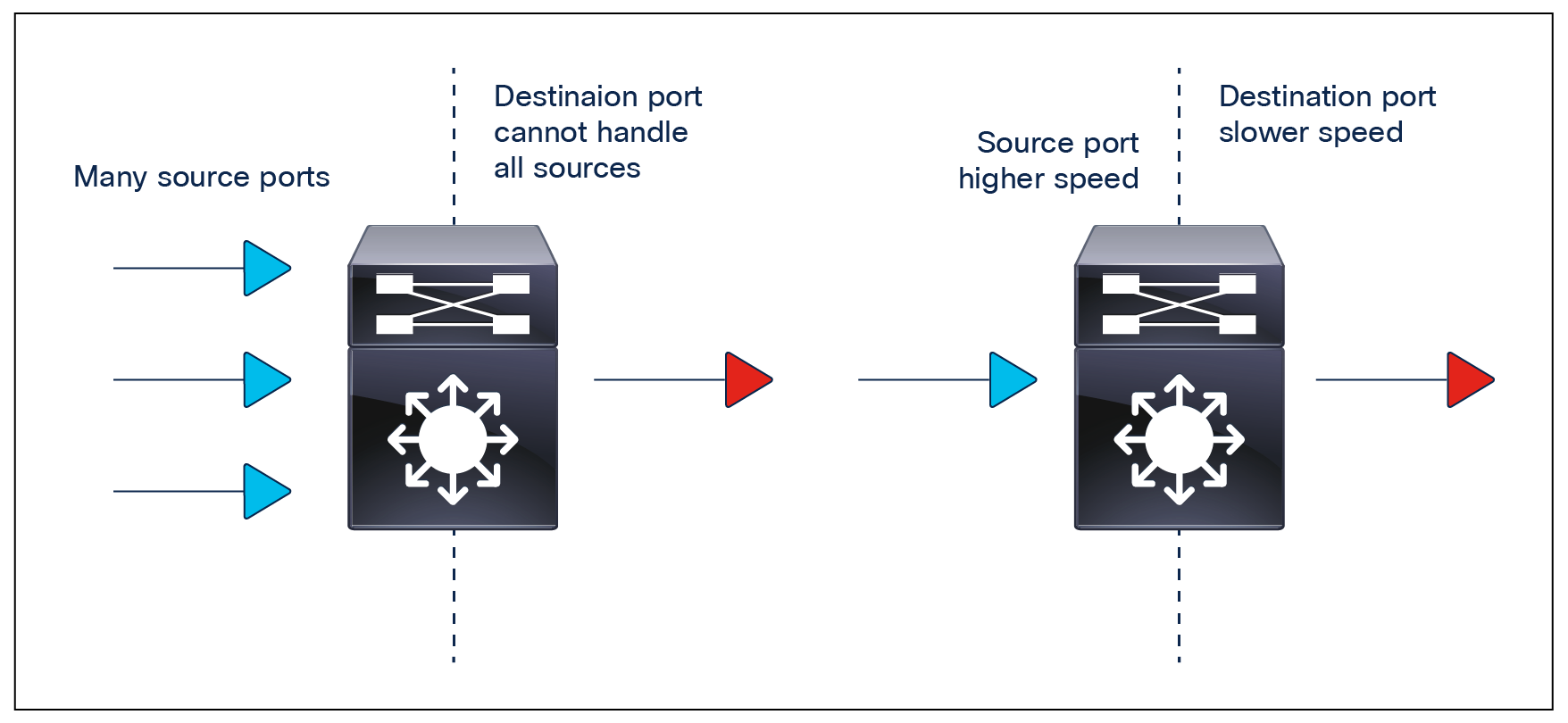
The two causes of congestion
Congestion is a lot more common than you might expect in an enterprise network. Below are a couple of illustrative examples of perfectly valid network designs leading to congestion points in the network.
Two network designs that lead to congestion points
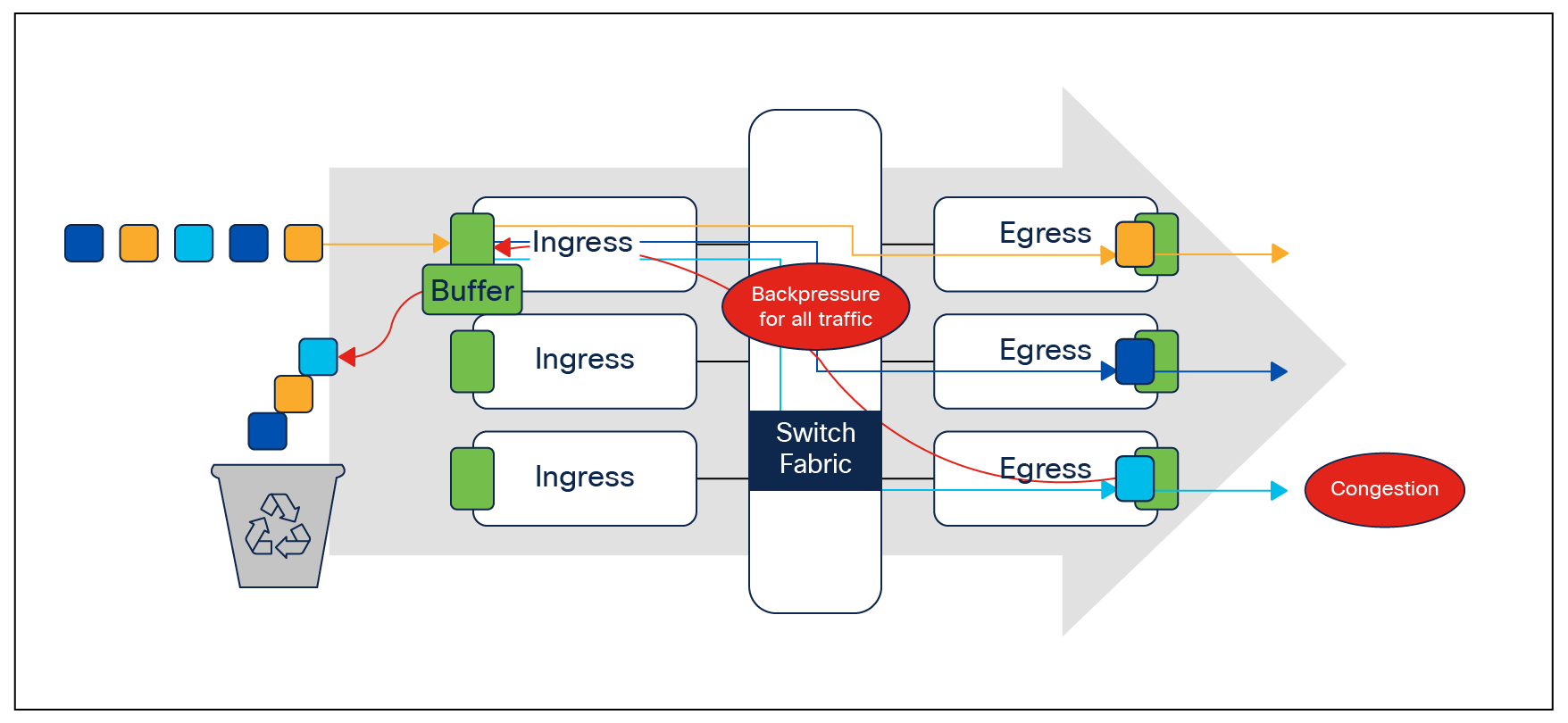
When we are dealing with high-speed networks, we must be aware of a phenomenon called head-of-line (HoL) blocking. Here we see packets held up by the head of the line, that is, the first packet in the queue. Until the first packet is processed and queued out, the remaining packets will not be processed.
Head-of-line (HoL) blocking
Let’s look at an example. In the figure above, we have three egress interfaces but a common ingress point. Consider a scenario where there is congestion in one of the egress interfaces. This creates back-pressure on the common ingress interface, leading to traffic destined to the remaining two uncongested ports also being impacted.
Why do we care about congestion?
Without QoS configuration, when congestion occurs, packets will be dropped indiscriminately. When packets are dropped, depending on the upper-layer protocol, retransmissions can occur, or networks might have to reconverge. In the case of retransmissions, the network performance can be impacted. In an already congested network, this can add to existing performance issues and potentially further degrade overall network performance. It can also result in temporary or full loss of connection in the case of Border Gateway Protocol (BGP), Open Shortest Path First (OSPF), Link Aggregation Control Protocol (LACP), etc., as the control plane protocols may not hear their keep-alive messages due to drops.
With high-speed networks, congestion management is even more critical. Latency- and jitter-sensitive traffic such as voice and video can be severely impacted if delays occur. A simple addition of buffers is not always the solution. Understanding the traffic pattern of the applications and what they are affected by is a key step before looking into the solution.
To ensure QoS for a particular application, a certain set of tools might be required. The Cisco Catalyst 9000 platforms provide all the required tools to handle the applications commonly found in enterprise networks.
There are a few ways to manage congestion:
● Reduce the oversubscription ratio (i.e., use higher-speed interfaces).
● Use a queuing scheduler to prioritize traffic.
● Use congestion management algorithms such as weighted random early detection (WRED) or weighted tail drop (WTD) to drop some of the traffic earlier.
● Use buffers to reduce drops and increase the stored packets before transmitting.
● Police the traffic on ingress to reduce the traffic on egress.
The next section discusses how the different QoS features are integrated into the Cisco Silicon One ASIC.
QoS integration in the Cisco Silicon One ASIC
The Cisco Silicon One application-specific integrated circuit (ASIC) powers the Catalyst 9500X switches and the Catalyst 9600X Supervisor Engine 2 (Sup2). The other switches in the Catalyst 9000 family are powered by variants of the Cisco Unified Access Data Plane (UADP) ASIC.
Both the Catalyst 9500X switches and the Catalyst 9600X Sup2 run on a slice-based ASIC with a VoQ model. VoQ is a technique to address the HoL block phenomenon with ingress buffering, as explained above.
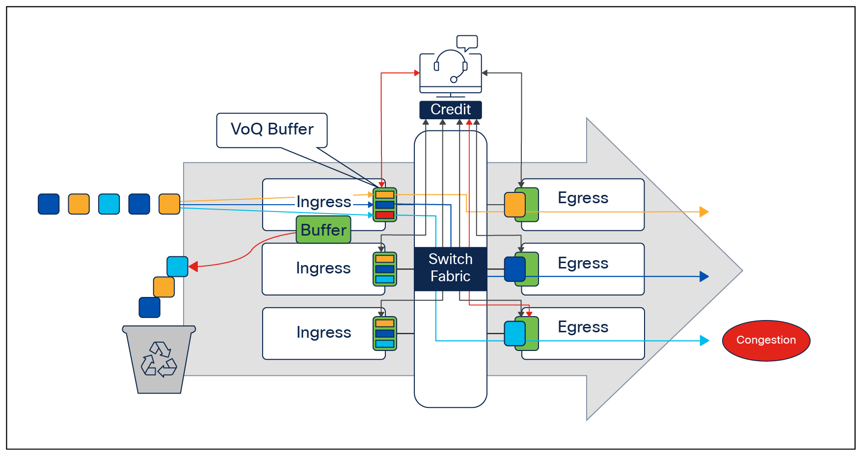
Virtual Output Queuing (VoQ) forwarding model
VoQ is a technique in switch architecture where, instead of keeping all traffic in a single queue, we have individual, unique virtual queues between each output and input point.
In the event of congestion occurring on one of the egress ports, only the corresponding virtual ports are affected. The other virtual ports corresponding to other egress ports are unaffected and will be serviced by the credit scheduler. The credit scheduler works on a round-robin format where it provides a credit to each port for forwarding traffic. The ingress port can send traffic toward the egress only when it receives a credit from the scheduler.
This ensures that traffic for those other egress ports will continue to process and forward traffic without encountering any dropped traffic.
VoQ forwarding model
In the same example, we now have separate virtual queues between the ingress and each individual egress port. So the effects of congestion on one egress interface will not be experienced by the other interfaces due to their virtual queues with the ingress being healthy.
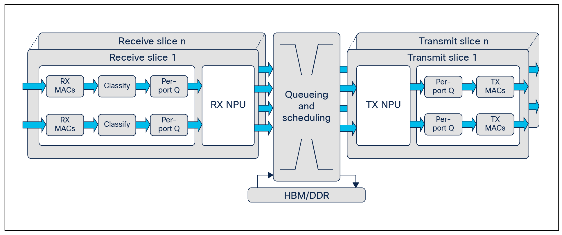
Multi-slice architecture
Cisco Silicon One ASICs uses a multi-slice architecture that is an evolution of the multi-core architecture used in the UADP-powered Catalyst 9000 switches. The Q200 enables up to six slices, while the K100/E100 uses two slices, and A100 uses one slice.
Slice architecture
All switches in the Cisco Catalyst 9000 family run a Cisco IOS® XE image, except for the Catalyst 9200 Series (which uses the Cisco IOS XE Lite image). Cisco IOS XE is an enhanced, open, and programmable OS. With a 30-year history behind it and thousands of features, Cisco IOS XE is arguably the most feature-rich OS in the networking industry. The modular nature of Cisco IOS XE makes it possible to load the same binary image on both the Cisco Silicon One Q200 and UADP-powered switches.
While features and capabilities differ between the ASICs, having a single operating system shared across the Cisco Catalyst 9000 platforms helps when qualifying a software release, as only a single image needs to be tested for the entire campus network. Another benefit of having the same software image is that the same building blocks are used to configure QoS in the device.
The differences between the QoS models and capabilities are mostly abstracted from the end user, as both models use the same Modular QoS Command-Line (MQC) model, making the majority of the configurations similar.
Note, however, that while the same Cisco IOS XE image is run on both the Cisco Silicon One powered switches and the UADP-powered switches, the configurations, syntax, and supporting QoS actions differ between the two platforms.
MQC model
The MQC model is a standard way of configuring QoS across different product lines. The Catalyst 9000 switching family uses the same MQC model as a structured way to configure the different QoS tools such as policers, shapers, traffic remarking features, etc.
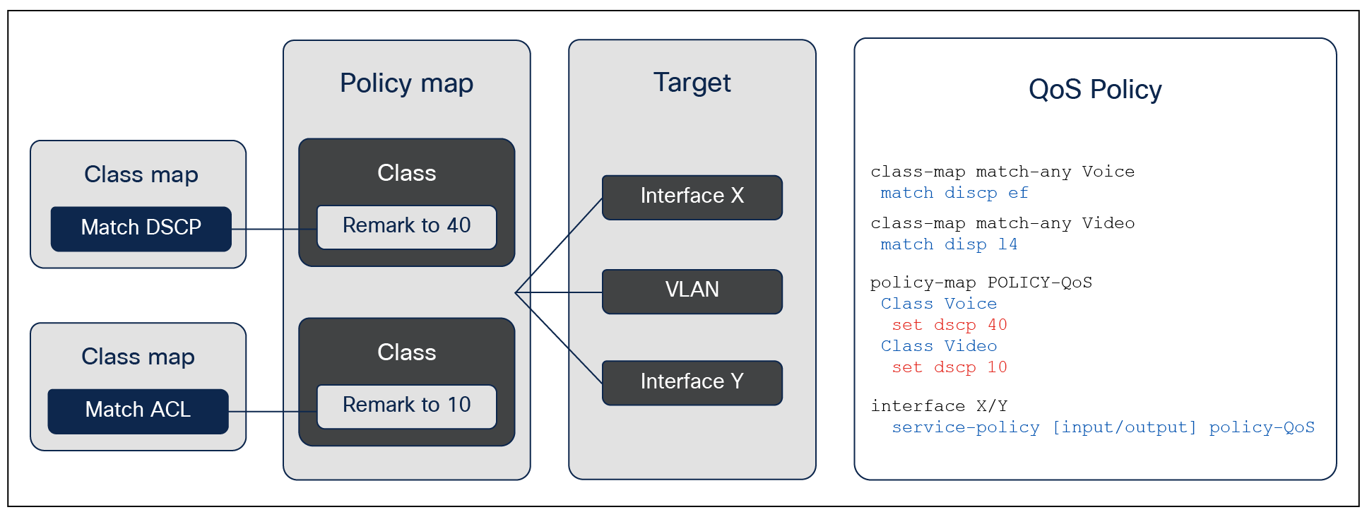
Every MQC policy is based on a class map, a policy map, and an interface target where the policy map will be attached. The figure below shows an MQC policy structure.
MQC configuration model
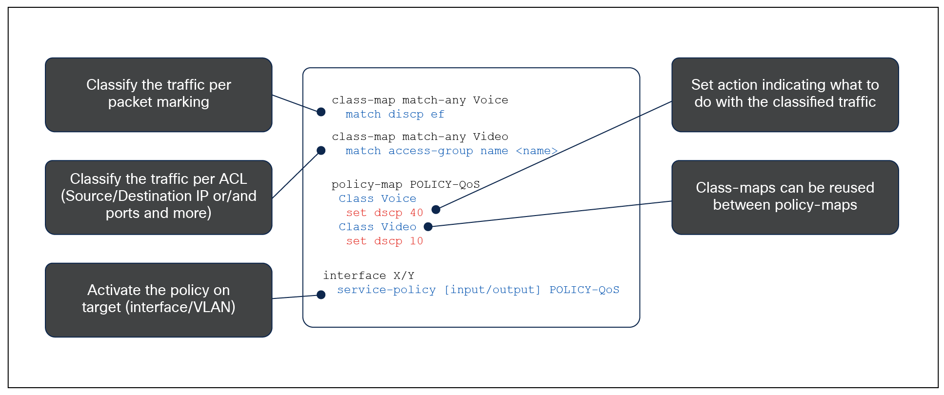
The following figure shows an example of an MQC QoS policy.
Configuration example
The QoS tools can be categorized as ingress and egress. Each section has its own associated actions and capabilities. The two QoS tool sets are discussed later in this white paper. A combination of these tools can be used to achieve the desired quality of service in your network.
Merely increasing the size of the buffer doesn’t always mean improved packet performance across the switch. Buffering needs differ based on the network requirements. For example, shallow buffers will switch out packets quickly but fail to address traffic burstiness and speed mismatches that can cause congestion. On the other hand, deep buffers will inevitably introduce higher latency, which is something to avoid, especially for higher-priority or time-sensitive packets.
Depending on the platform, we have a hybrid buffering model with two types of buffers for different traffic requirements:
● A pool of specialized buffers to switch packets with the lowest latency
● An on-demand deeper pool of buffers that can be used to address micro-bursts and speed imbalances
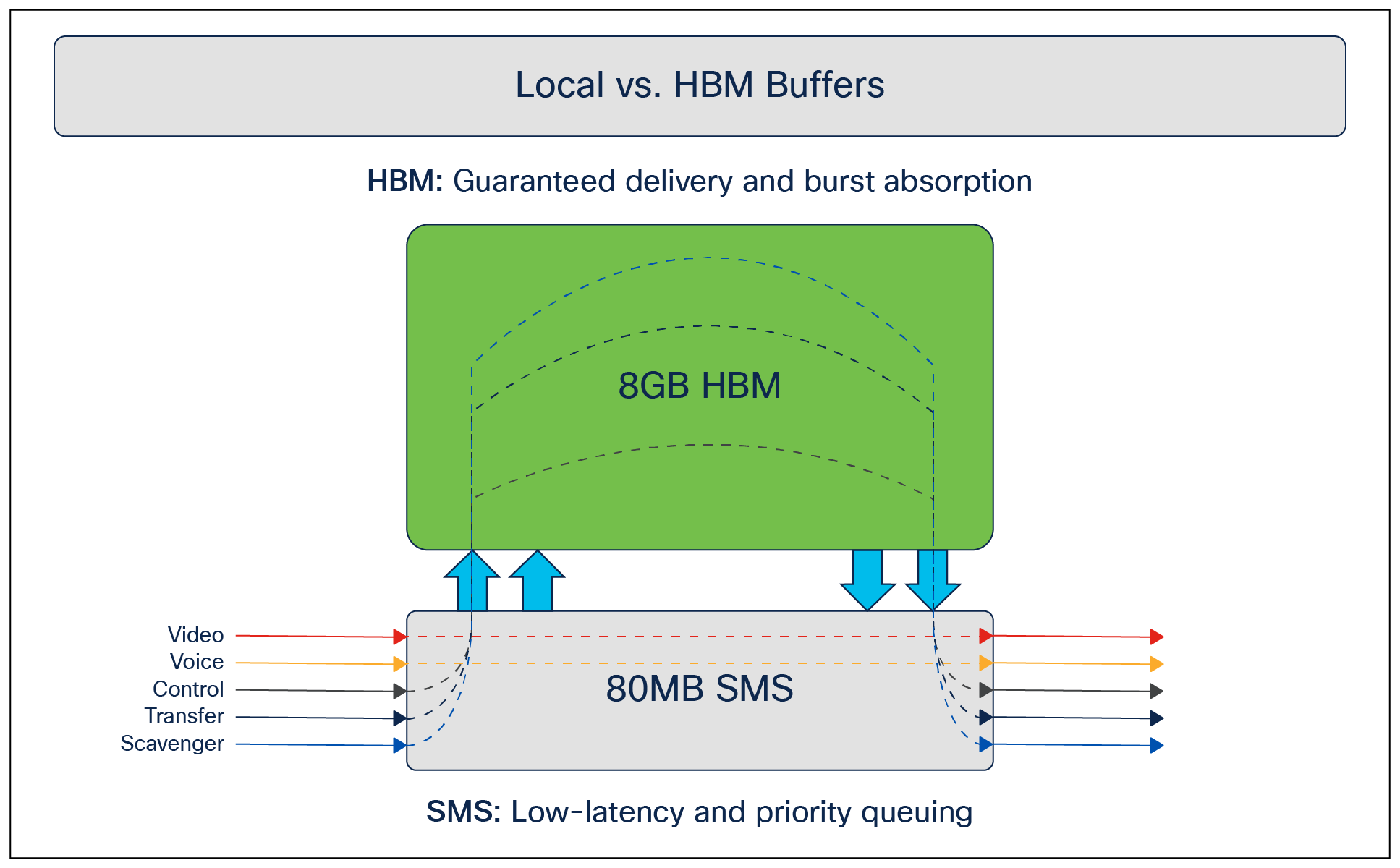
The pool of specialized buffers is the Shared Memory Subsystem (SMS). These buffers are used specifically for low-latency queueing. The priority queue will always make use of SMS buffers regardless of whether the platform supports external buffers to ensure that overall latency remains low.
To address micro-bursts and cases where there are speed imbalances between the ingress and egress ports, certain high-performance models have a deep pool of on-demand High-Bandwidth Memory (HBM) buffers totaling 8 GB. This provides sufficiently deep buffering for packets in cases where latency is not a problem and the need is to queue the packet and send it out regardless of the congestion/burstiness of the traffic. The following figure shows the two different types of buffers and their use cases.
SMS and HBM buffers
All traffic always hits the SMS first. The packet, based on priority, is evicted to the HBM in the event of congestion for queueing, and when the packet is ready to be processed and sent out, the HBM sends the packet back to the SMS to forward to the output queues.
All this buffering occurs before the packet hits the output queue. In the Cisco Silicon One ASIC VoQ architecture, once the packet reaches the output queue, there is no further buffering, and the packet will be sent out of the output interface.
The sizes of the buffers per platform are listed below.
● Cisco C9350 Series Smart Switches (A100L) – 18 MB of SMS buffers and no HBM buffers
● Cisco Catalyst 9500X Series Switches (Q200) – 80 MB of SMS buffers with 8 GB of HBM buffers
● Cisco Catalyst 9600X Supervisor Engine 2 (Q200) – 80 MB of SMS buffers with 8 GB of HBM buffers
● Cisco C9610 Supervisor Engine 3 (E100) – 64 MB of SMS buffers with no HBM buffers
● Cisco C9600 Supervisor Engine 3XL (K100) – 64 MB of SMS buffers with 8 GB of HBM buffers
Buffer behavior during congestion
It is never advisable to wait for congestion to occur and then take corrective action. This will lead to increasing degradation of traffic forwarding until it reaches 100% congestion, at which point all traffic will stop forwarding for the port/VoQ. The SMS will look for early signs of congestion and take corrective action by punting packets to HBM, if available, long before actual full congestion occurs. The queue size and queue delay (the time that packets are in the queue) are triggers that are used to detect early signs of congestion.
The process of the packets being evicted to the HBM is dynamic and cannot be edited by the user.
Understanding how the switch “reads” priority
Let us look at a very simple MQC configuration which can be applied to a Catalyst 9000 switch.
class-map match-all REALTIME
match dscp ef
policy-map EGRESS
class REALTIME
priority level 1
The config simply checks the header of all packets coming into the switch and, if it matches EF (dscp value of 46), then it treats the packet as priority level 1. While the device is processing this packet and sending it out on the wire, all other packet processing is paused.
In other words, the UADP-based switches can read the packet header (either dscp, cos or ip prec tags) and directly prioritize or de-prioritize them as required. The Silicon One devices cannot do this. These devices instead use a tag called the traffic-class to perform priority checks. The traffic-class and traffic-color are two tags which are appended to the packet header when it enters the switch and removed when it exits the switch.
First this creates an overhead.
This creates a mandatory overhead, where the user must define the mapping of the dscp/cos/ip prec tags to the appropriate traffic-class. Once this is done, we can use the traffic-class to prioritize traffic.
So to use QoS to prioritize and de-prioritize traffic, two things need to be done:
1. Map the dscp/cos/ip prec tags to traffic-class as the traffic comes into the switch.
2. Prioritize and de-prioritize the traffic based on the traffic-class as it exits the switch.
But what is the traffic-class? The traffic-class is an 8-bit field that is added to the packet header when the packet enters the switch and removed when it exits the switch. It can have values ranging from 0 to 7, with higher numbers generally signifying higher priority.
Each traffic-class can be considered as a separate queue, allowing for different traffic to enter different traffic-classes and therefore be prioritized accordingly. With traffic-classes from 0 to 7, we can have a total of 8 different queues.
There are some hard-set rules when defining traffic-classes.
1. Traffic-class 7 is ALWAYS a priority queue with priority level of 1.
2. Traffic-class 0 is ALWAYS class-default and CANNOT be a priority queue.
3. Any traffic not matching any of other traffic-classes will be assigned to traffic-class 0.
4. Remaining traffic-classes 6 to 1 can either be a normal queue or a priority queue.
5. Priority levels must be sequential. Some examples.
a. If we want two priority queues, then traffic-class 7 must be enabled for priority level 1 and traffic-class 6 must be enabled for priority level 2.
b. If we want three priority queues, then traffic-class 7, 6, and 5 must be enabled for priority levels 1, 2, and 3, respectively.
6. 8Q and 8P are unsupported. We support 1P7Q to 7P1Q configurations.
Mapping of traffic classes
Example configuration.
policy-map INGRESS
class REALTIME (matching dscp ef)
set traffic-class 7
class VIDEO (matching af41)
set traffic-class 6
class class-default
In this example, we are mapping ef to traffic-class 7 and af41 to traffic-class 6. Any traffic that does not match these mappings will be sent to traffic-class 0. (For example, a dscp tag of 24 does not have an explicit mapping, so will use traffic-class 0.) This can then be applied on the ingress interface.
Interface gi 1/0/1
Service-policy input INGRESS
This completes the first step, where we have mapped the dscp/cos/ip prec of incoming packets to appropriate traffic-classes. Now we can perform queueing on the traffic-classes as the traffic leaves the switch. The example config is continued below.
Policy-map type queueing EGRESS
Class tc7 (matching traffic-class 7)
Priority level 1
Class tc6 (matching traffic-class 6)
Priority level 2
Class tc5 (matching traffic-class 5)
Bandwidth remaining percent 10
Class class-default (traffic-class 0)
Bandwidth remaining percent 15
And apply on the interface where traffic goes out.
Interface gi1/0/10
Service-policy type queueing output EGRESS
Let us focus on class tc5 in the configuration above. This class is matching traffic-class 5; however, in the ingress policy, we never defined a traffic-class 5. This config will be accepted (we will look at a use case in a second), but keep in mind that in this current state, this queue will not be used.
Now, in what situation would this be useful? To illustrate this, we need to better understand the concept of VoQs. Virtual queues are built at the INGRESS. In the above example, we built VoQs (over tc7, tc5, and tc0) between Gi1/0/1 and Gi1/0/10. Since we never built a VoQ over tc5 between G1/0/1 and G1/0/10, that queue on G1/0/10 is unused.
Let’s look at a slightly more complex example.
Two ingress ports with a common egress port
Just focus on the highlighted sections here. We have two ingress ports, INGRESS-1 and INGRESS-2, and a common EGRESS port. We are building the following VoQs.
VoQ between INGRESS-1 and EGRESS:
● Over tc7 (matching dscp ef)
● Over tc6 (matching dscp af41)
● Over tc0 (matching all other dscp tags)
VoQ between INGRESS-2 and EGRESS:
● Over tc7 (matching dscp ef)
● Over tc6 (matching dscp 26)
● Over tc5 (matching dscp af41)
● Over tc0 (matching all other dscp tags)
Focus only on packets tagged af41. At EGRESS, we can differentiate this traffic based on whether we receive it from INGRESS-1 (goes to tc6 – priority level 2) or INGRESS-2 (goes to tc5 – normal queue) This allows for granular control of the priority of the same tagged traffic, depending on the source of the packet.
Let us now look at the naming convention, specifically for the class-maps.
On the ingress, when you are mapping the packet header information to the traffic-class, you are free to use any custom name for the class-maps.
Example ingress policy
However, on the egress policy, where you are queueing based on the traffic classes, you can use only the predefined class names (tc7 to tc1 and class-default).
Example egress policy
Custom naming of the class-maps on the egress queueing policy is NOT permitted. This makes it easier to queue on the basis on the traffic-classes.
Now, let us talk about traffic-color in more detail. Like traffic-class, traffic-color is added to the header when the packet enters the switch and removed when it exits the switch. It is a 2-bit value (can have a value of either 0 or 1). Internally, this field is referred to as discard-class.
● A value of 0 is referred to as color green.
● A value of 1 is referred to as color yellow.
With no configs, by default, all traffic as it enters the switch will have the value 0 (green) as the traffic-color appended to the packet header. We can tweak this by manually coloring traffic (conditionally or unconditionally) to yellow (setting the value to 1). This must be done where the traffic enters the switch, so at ingress. Examples of configuration are given in the later section below.
Trust
On Cisco Catalyst 9000 family switches, all incoming packets are trusted by default. The markings on the packets as they come in do not change (are trusted) unless a policy being applied for that packet changes the marking.
Conditional trust
Cisco Catalyst 9000 family switches support conditional trust, which enables you to trust certain types of devices. The trust device command at the port level facilitates this capability. Once the trust device command is applied to a port, the port will trust only the trusted device. Packets from any other devices will not be trusted, and differentiated services code point (DSCP), IP precedence, or class of service (CoS) will be remarked to 0.
For example, in the following configuration, only Cisco IP phones will be trusted. All other traffic will be remarked to 0.
interface <interface name>
description IP Phone
switchport access vlan 99
switchport mode access
trust device cisco-phone
Conditional trust can be enabled for only one device type on a port at a time. Although it is possible to have multiple devices on a single port, it is not possible to enable conditional trust for multiple device types at the same time.
For example, there might be an IP phone connected to the switch and a PC connected to the phone. IP phones are configured as trusted devices, while PCs are not. This can be a problem when provisioning trust in a mobile environment. Consider the following example:
● Port A is configured to trust the endpoint connected to it, which initially is an IP phone.
● Port B is configured not to trust the endpoint connected to it, which initially is a PC.
Because of a move, these endpoints get plugged into the opposite ports. This breaks the quality of voice over IP (VoIP) calls made from the IP phone (now plugged into untrusted port B) and opens the network up for unintentional or deliberate abuse of provisioned QoS by the PC (now plugged into the trusted port A).
One solution is to have an intelligent exchange of information between the switch and the devices plugged into its ports. If the switch discovers a device that is trustworthy, it can extend trust to it dynamically. In the current Cisco implementation, the intelligent exchange of information is performed using Cisco® Discovery Protocol (CDP).
Typically, IP phones have the ability to mark 802.1Q/p CoS values for both VoIP and call signaling (default values are 5 and 3, respectively). Furthermore, they also have the ability to mark VoIP as DSCP Expedited Forwarding (EF) and call signaling as DSCP Class 3 (CS3).
Classification
Ingress classification is applied in the ingress interface when the packet comes into the switch on an interface with an ingress policy map applied.
A key difference between the existing UADP QoS model and the Cisco Silicon One model is that the classification step is important and mandatory. Traffic must be identified and assigned an appropriate traffic class using an ingress policy map. Matching DSCP, CoS, MPLS EXP, VLAN, and ACLs in egress queueing policy maps is not supported.
Traffic class
The goal of ingress classification is to map the incoming traffic to one of eight traffic classes. Traffic-class is a 3-bit value (from 0 to 7) unique to the switch and is not carried over to other devices in the network when the traffic egresses out. Traffic-class can be used to assign up to eight levels of priority to traffic coming into the switch. TC7 (traffic-class 7) has the highest priority, and TC0 (traffic-class 0) has the lowest priority.
Egress policy maps (discussed below) directly rely upon the traffic-class tags assigned at the ingress to perform the queueing and scheduling actions. Thus, it is mandatory to match the traffic to a corresponding traffic class at ingress. Failure to do so will result in default mapping of DSCP or CoS to traffic classes in egress, leading to unwanted results.
Ingress classification can be performed using the following:
● Access control lists (ACLs) (source/destination IPs, TCP/UDP ports, and more)
● DSCP
● CoS
● MPLS experimental bits (EXP)
● VLANs
● IP precedence
The classification can use logical operators such as “AND” or “OR” between multiple classification parameters.
The following example highlights the differences between the “AND” and “OR” logical operators.
class-map match-any VOICE
match ?
access-group Access group
--- Or ---
dscp Match DSCP in IPv4 and IPv6 packets
Note: “match-any” specifies to match on the access-group OR DSCP value.
class-map match-all VOICE
match ?
access-group Access group
--- And ---
dscp Match DSCP in IPv4 and IPv6 packets
--- And ---
vlan VLANs to match
Note: “match-all” specifies to match on the access-group AND DSCP value AND VLAN.
In addition to setting the traffic class, classification result can be used for:
● Policing
● Conditional or unconditional coloring
Policing
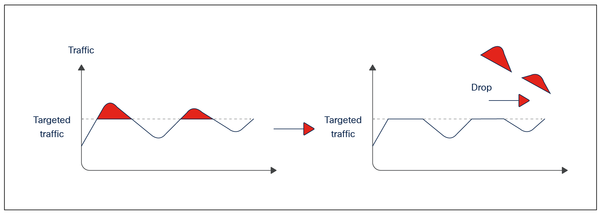
Policer is a QoS tool that is used to reduce the ingress rate to a desired value. This section explains how policers achieve traffic reduction by immediately dropping the excess traffic.
Policing
The parameters used to configure policers are as follows:
● Policer rate and burst
Two key parameters in the configuration of policing are rate and burst. The rate (also referred to as the committed information rate, or CIR) is defined as the maximum amount of data that can be forwarded in a given interval (normally referred to in Kbps, Mbps, or Gbps). The total amount of data that can be received in a given interval is called the burst.
A simple example of how these parameters interact could be a policy that uses a rate of 10 Mbps and a burst of 11 Mbps. This policy specifies that a maximum of 11 Mbps can be received in a given interval from which 10 Mbps (the rate) of data can be sent. The burst can be thought of as how much data can be received (imagine a bucket that can be filled), while the rate defines how much data can be forwarded (imagine how quickly the bucket is emptied).
An important point to stress is that the burst should never be less than the stated rate. If, for example, the burst was set at 8 Mbps, a rate of 10 Mbps would be impossible to achieve. If the bucket (burst receive size) can only ever hold 8 Mb, the maximum rate could be only 8 Mbps as well.
● Peak information rate and max burst
Peak information rate (PIR) and max burst are the next set of parameters that must be understood. If rate and burst are associated with the first bucket, the PIR and max burst are associated with a second bucket. The max burst defines the depth of the second bucket, while the PIR is the amount of data that can be forwarded from the second bucket. One way of thinking of PIR is as an extra-small bucket that allows additional rate if resources are available.
Packet color
Packet color is a method of identifying traffic types introduced with Cisco Silicon One switches. Here traffic can take on one of two colors, green or yellow. The color is determined by a 1-bit value (either 0 = green or 1 = yellow) called the discard class, and this is attached to the packet during the internal processing in the switch (the value does not carry over to other devices in the network ).
The packet color comes into play during congestion management and can be used by either WTD (weighted tail drop) or WRED (weighted random early detection) algorithms. During congestion, yellow packets will be dropped more aggressively than green packets, allowing for control over packet drops in the event of congestion.
Packet color can be set unconditionally using the command set discard-class 1:
policy-map ingress-policy
class class-5-green
set traffic-class 5
class class-5-yellow
set traffic-class 5
set discard-class 1
Policer and traffic color configuration
Conditional coloring of the packets is possible using policers. With this it is possible to color packets green by default, but when the rate of traffic exceeds a set rate the packets going over the configured rate will be yellow. This is achieved by calling the discard-class command on the exceed-action command of the policer:
policy-map ingress-policy
Class class-5
set traffic-class 5
police rate 5 gbps peak rate 10 gbps
exceed-action set-discard-class-transmit 1
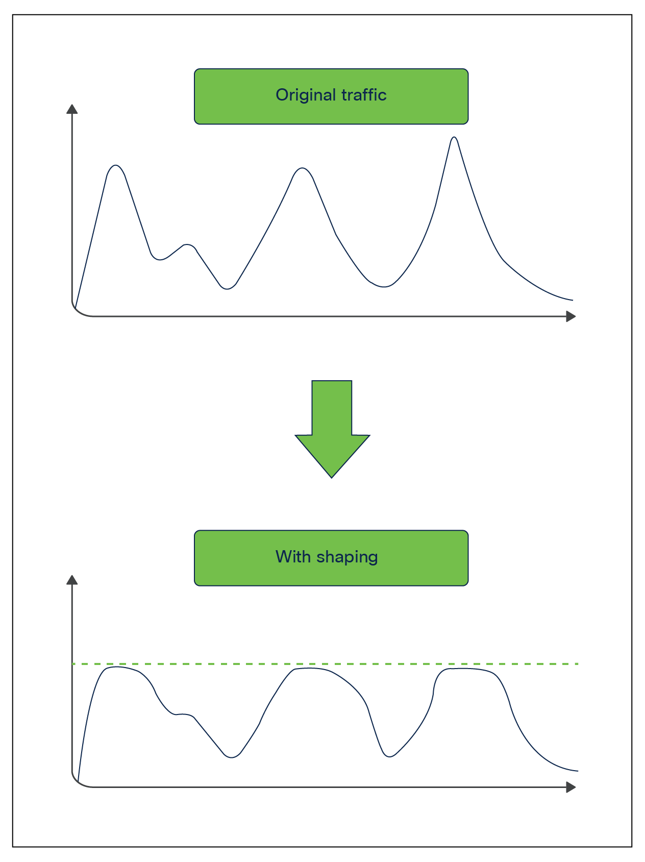
Shaping
Shaping is an egress QoS tool that can be used to limit the packets send out of a port queue. Shaping functions differently than policing, as it will try to use any free buffer space before dropping a packet, while policing drops the packet immediately. The buffered packets will be transmitted when the port gets further transmit cycles.
With shaping, a certain amount of traffic is buffered and sent out of the port when the burst disappears. Buffering adds delay to the packets as they wait to be transmitted.
The Cisco Silicon One ASIC permits a shaper for every output queue (up to eight output queues are supported per port).
Shaping
Egress classification and queueing
Egress classification is similar to ingress classification. The goal is to match specific traffic to one of eight classes. The difference is that in egress, the only supported operation is matching of the traffic class. We use the result of the classification at the ingress to match the traffic class and call it in a queueing policy map.
Queueing
The Cisco Silicon One ASIC supports up to eight queues per port. The scheduler takes the following options into account when allocating bandwidth to the queue.
● Is the queue a priority queue?
● What is the shape traffic limit?
● If it is not a priority queue, what is the weight of the queue?
At the ingress, we mapped the traffic to up to eight traffic classes, with TC7 being the highest priority and TC0 being the lowest. In the egress policy, we match the traffic hitting these traffic classes and assign the queueing parameters to them.
The Cisco Silicon One ASIC supports the following actions in egress queueing policy:
● Assign up to seven priority queues (one queue must be normal).
● Apply shaping to control the traffic rate.
● Use packet colors to manage congestion on nonpriority queues.
● Use weighted round robin (WRR) between nonpriority queues for granular control over bandwidth sharing between the queues.
Congestion management using packet colors
The packet colors applied on the ingress provide user control over traffic to be dropped in the event of congestion. The Cisco Silicon One ASIC supports two algorithms to control packet drop when congestion occurs.
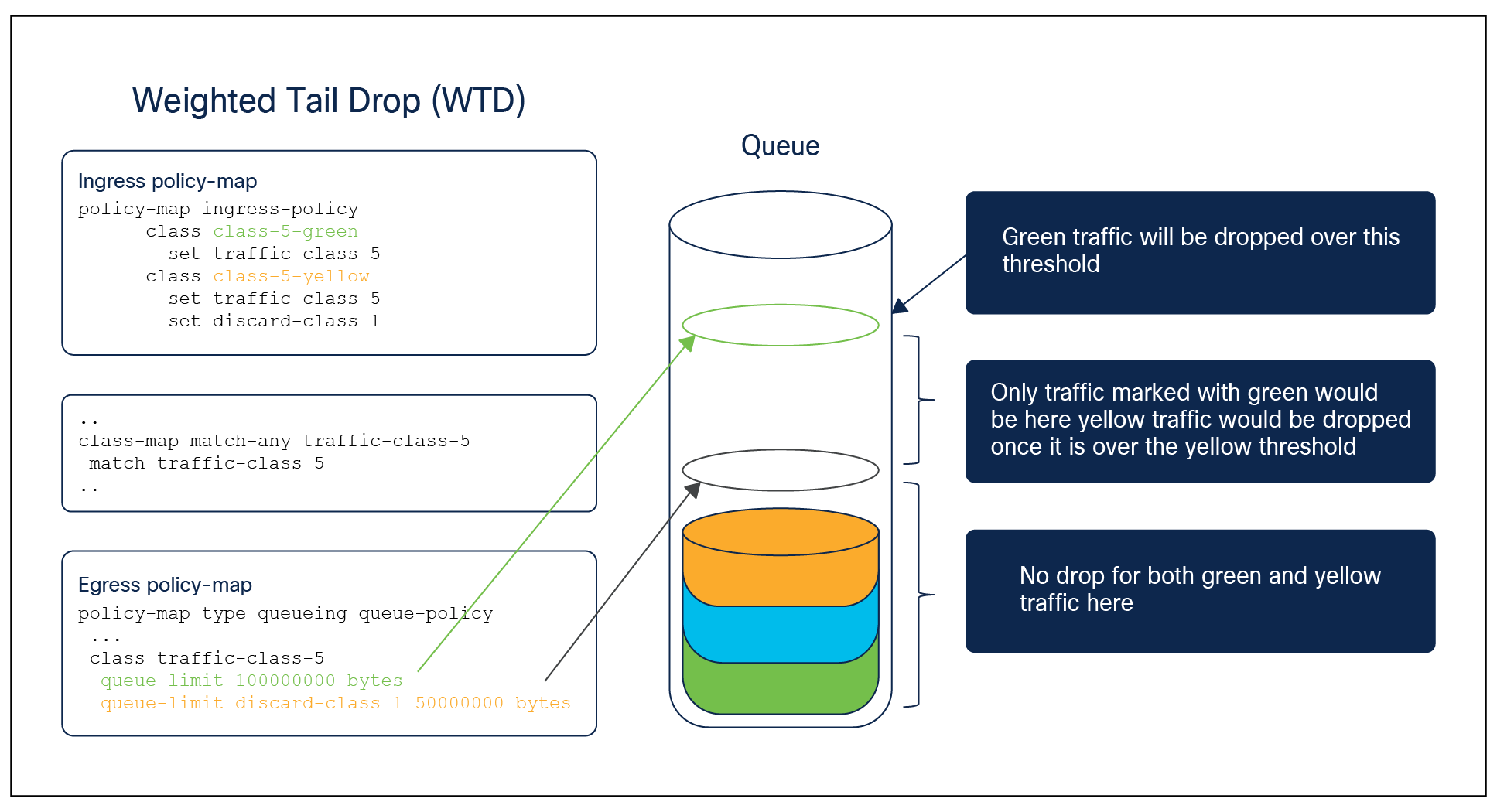
Weighted Tail Drop
Port queue thresholds are used to drop traffic earlier than the queue end (tail drop). If the port queue can drop specific traffic before the queue end, the port queue will keep buffer space for certain types of packets over the rest of the traffic managed by the port queue, based on the user configuration.
This is achieved using the command queue-limit in conjunction with the packet color. The figure below shows how WTD can be used to instruct the switch to drop yellow packets in the event of congestion.
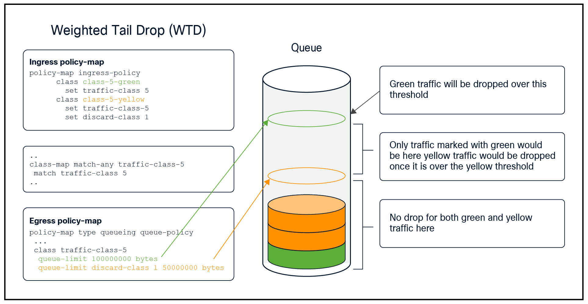
WTD configuration example
Weighted Random Early Detection
WRED is an algorithm for discarding frames in oversubscribed port queues randomly before the queue is full. WRED is based on the RED (random early detection) algorithm, using specific weights (priorities) to separate different traffic classes
Before we look at RED and WRED, let’s quickly revisit TCP flow management. Flow management ensures that the TCP sender does not overwhelm the network. The TCP slow-start algorithm (defined in RFC 2001) is part of the solution to address this. It dictates that when a flow starts, a single packet is sent, and then it waits for an acknowledgment (ACK). When the ACK is received, the TCP endpoint will send two packets and wait for the next ACK before sending more data. The number of packets sent each time gradually increases. This will continue until the flow reaches a transmission level (that is, sending x number of packets) that the network can handle without the load incurring congestion. Should congestion occur, the slow-start algorithm will throttle back the window size (that is, the number of packets sent before waiting for an ACK). This will normalize transmission to a set number of frames that the network can handle without dropping them.
RED monitors a queue as it starts to fill up. Once a certain threshold has been exceeded, packets will be dropped randomly. These packets could be from high- or low-priority flows, and from a single TCP flow or multiple flows. If multiple flows are impacted, as described above, it can have a considerable impact on each flow’s window size. However, this is not ideal, as random packets can be dropped.
This is where WRED comes in. Unlike RED, WRED is not so random when dropping packets. WRED takes into consideration the priority (traffic class) of the packets. This process allows for higher-priority flows to be kept intact, keeping their larger window sizes and minimizing the latency involved in getting the packets from the sender to the receiver.
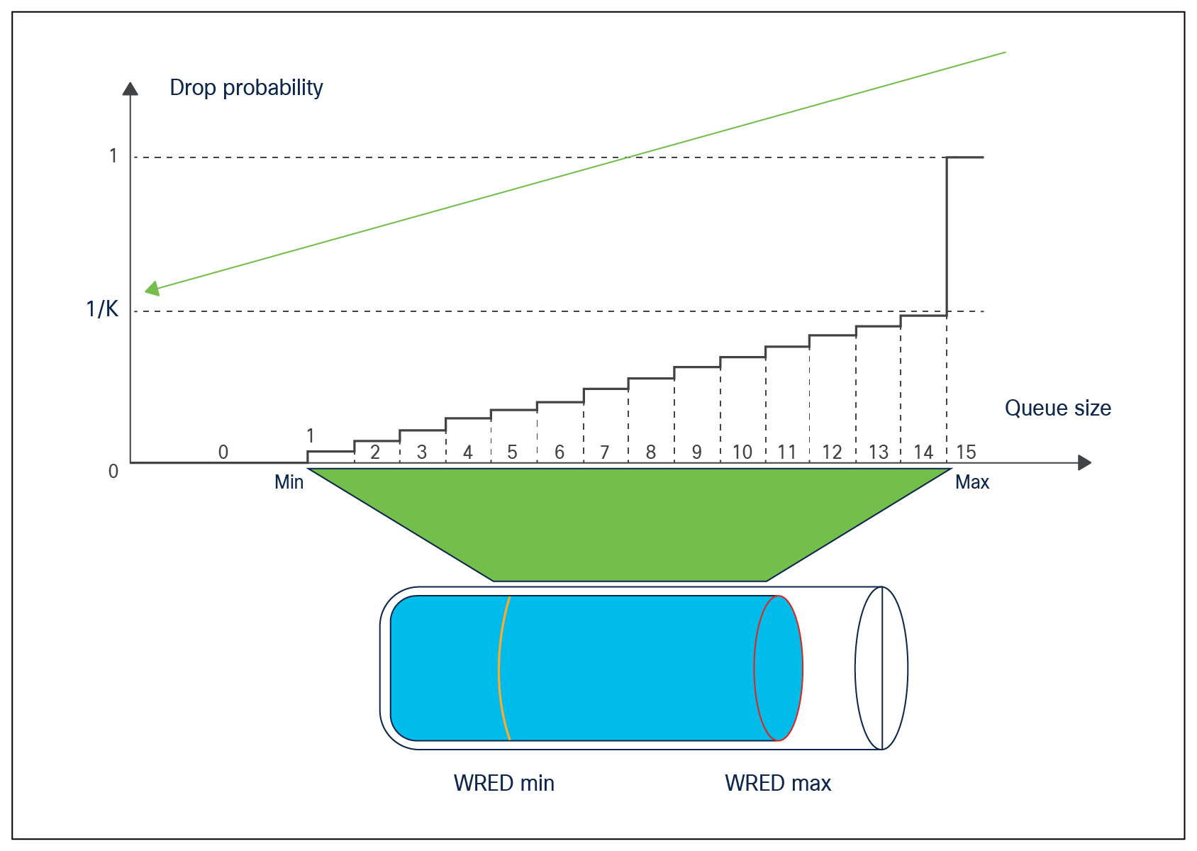
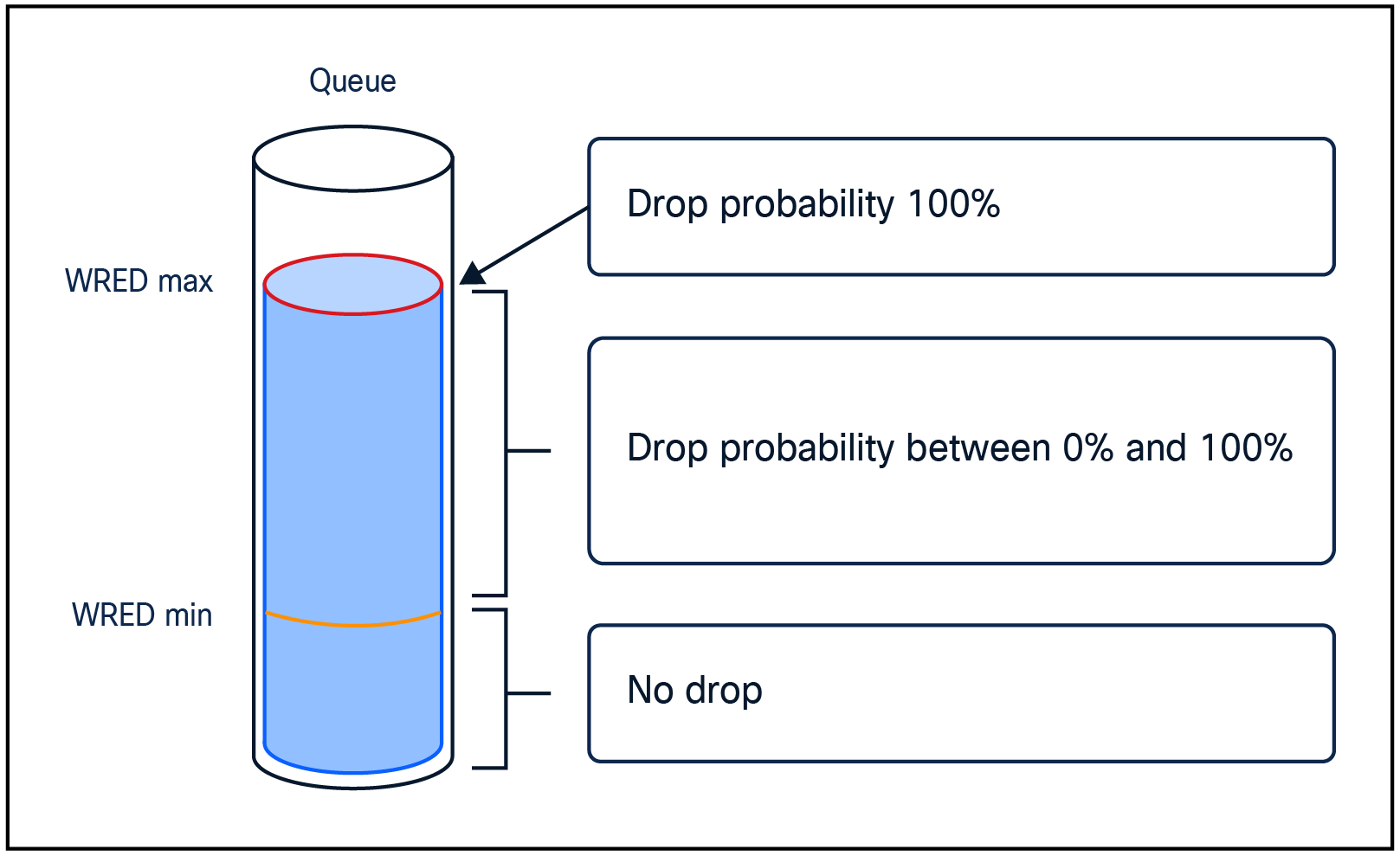
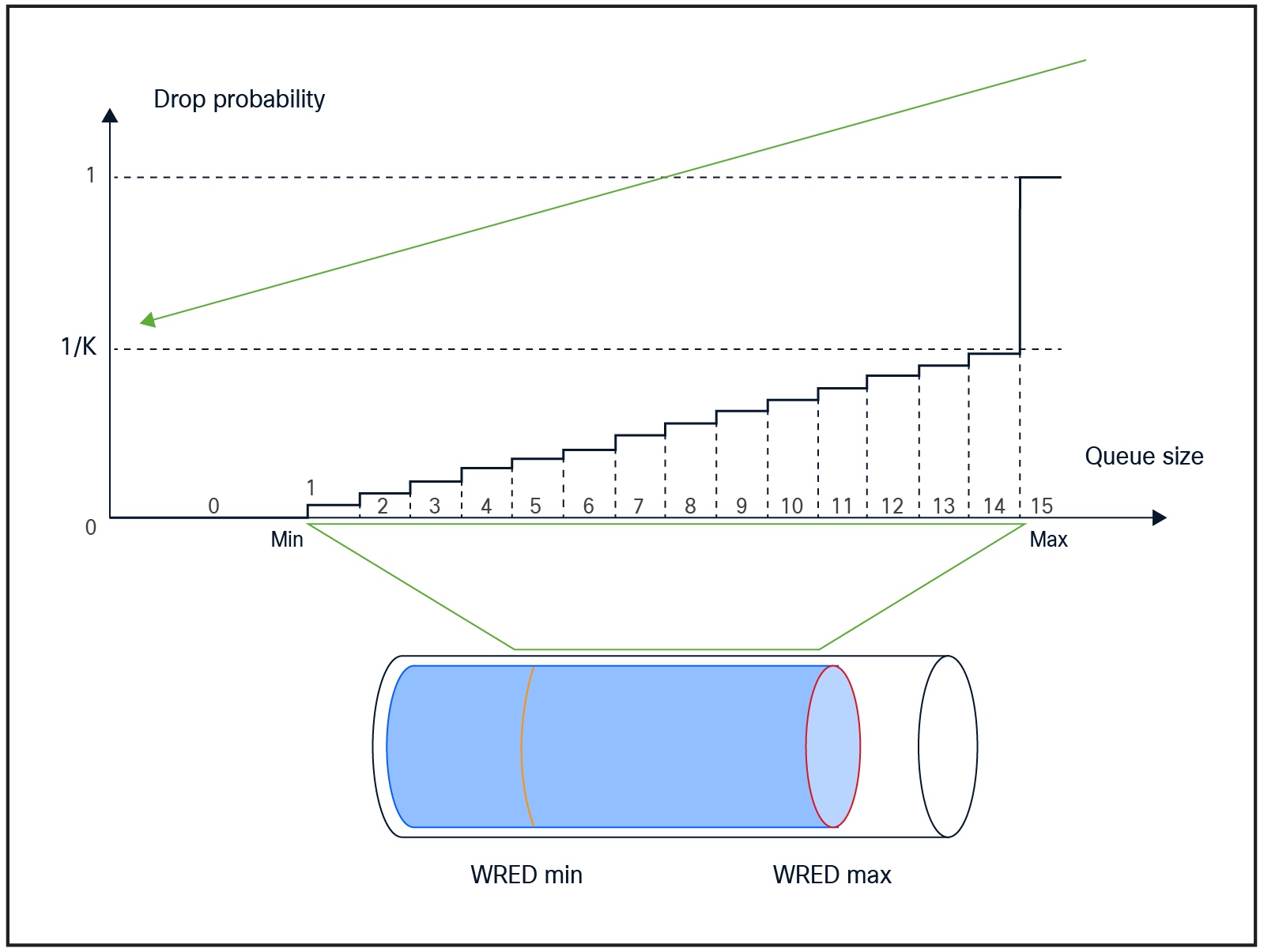
The WRED implementation is based on the Approximate Fair Drop (AFD) algorithm and queue utilization in the Cisco Silicon One ASIC. AFD is used to calculate the drop probability of a packet as the average of low and high threshold values. A packet that is being processed for forwarding can have up to 16 probabilities, depending on the size of the queue and how long the packet has been in the queue.
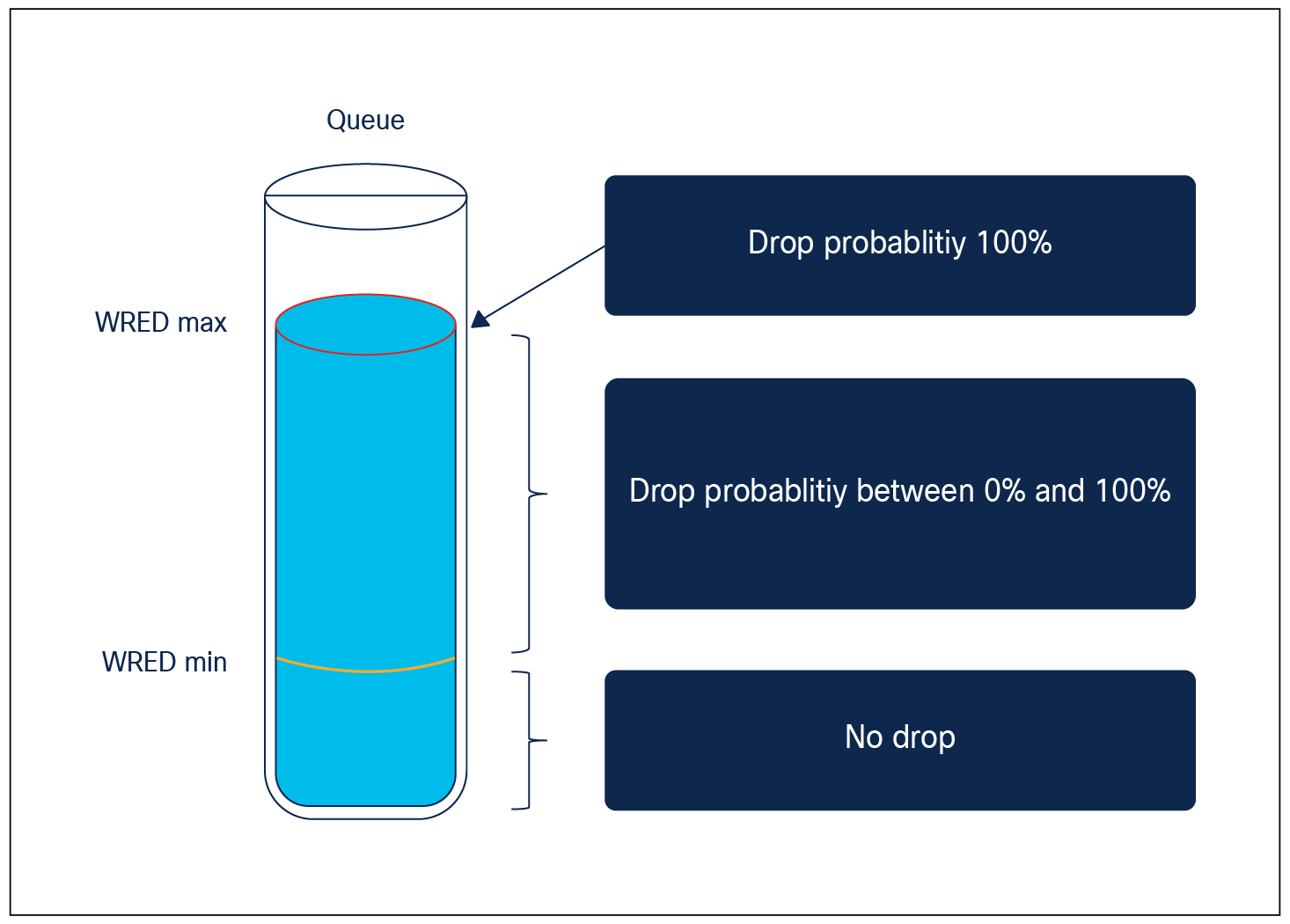
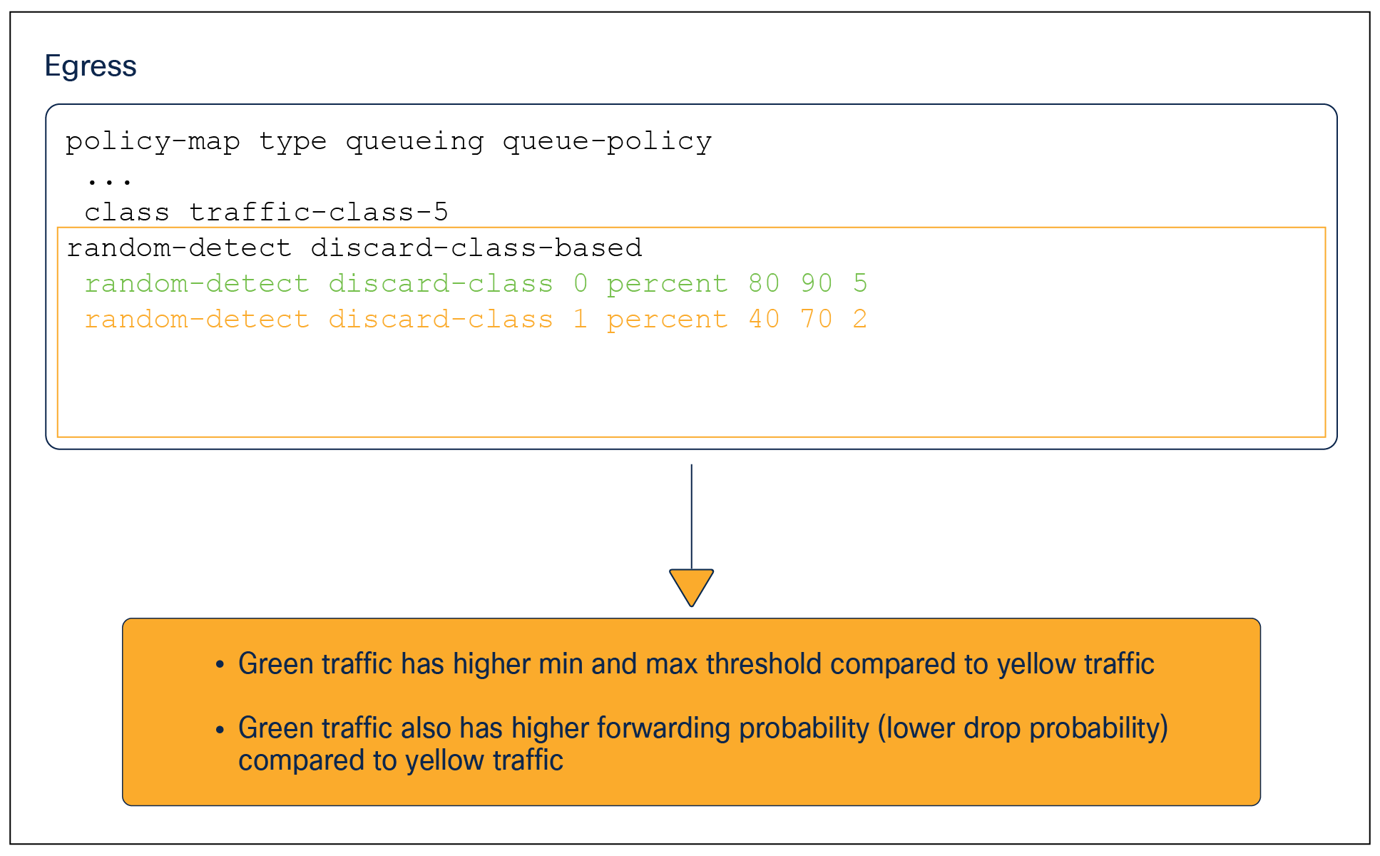
As part of the WRED configuration, we specify the lower and upper thresholds for both green and yellow traffic. The figure below shows how the thresholds are used to determine drop probabilities for the packets as the queue fills up.
WRED
We need to understand the WRED parameters before we start tweaking them.
Discard-class 0: This traffic is colored green.
Discard-class 1: This traffic is colored yellow.
Min-g: Minimum queue-size threshold in percentage for green traffic.
Max-g: Maximum queue-size threshold in percentage for green traffic.
K-g: Forwarding probability for green traffic. Higher numbers mean traffic has a higher chance of forwarding.
Min-y: Minimum queue-size threshold in percentage for yellow traffic.
Max-y: Maximum queue-size threshold in percentage for yellow traffic.
K-y: Forwarding probability for yellow traffic. Higher numbers mean traffic has a higher chance of forwarding.
WRED drop probability graph
Commands:
random-detect discard-class-based (default and only available WRED algorithm)
random-detect discard-class <0-1> percent <Min> <Max> <K>
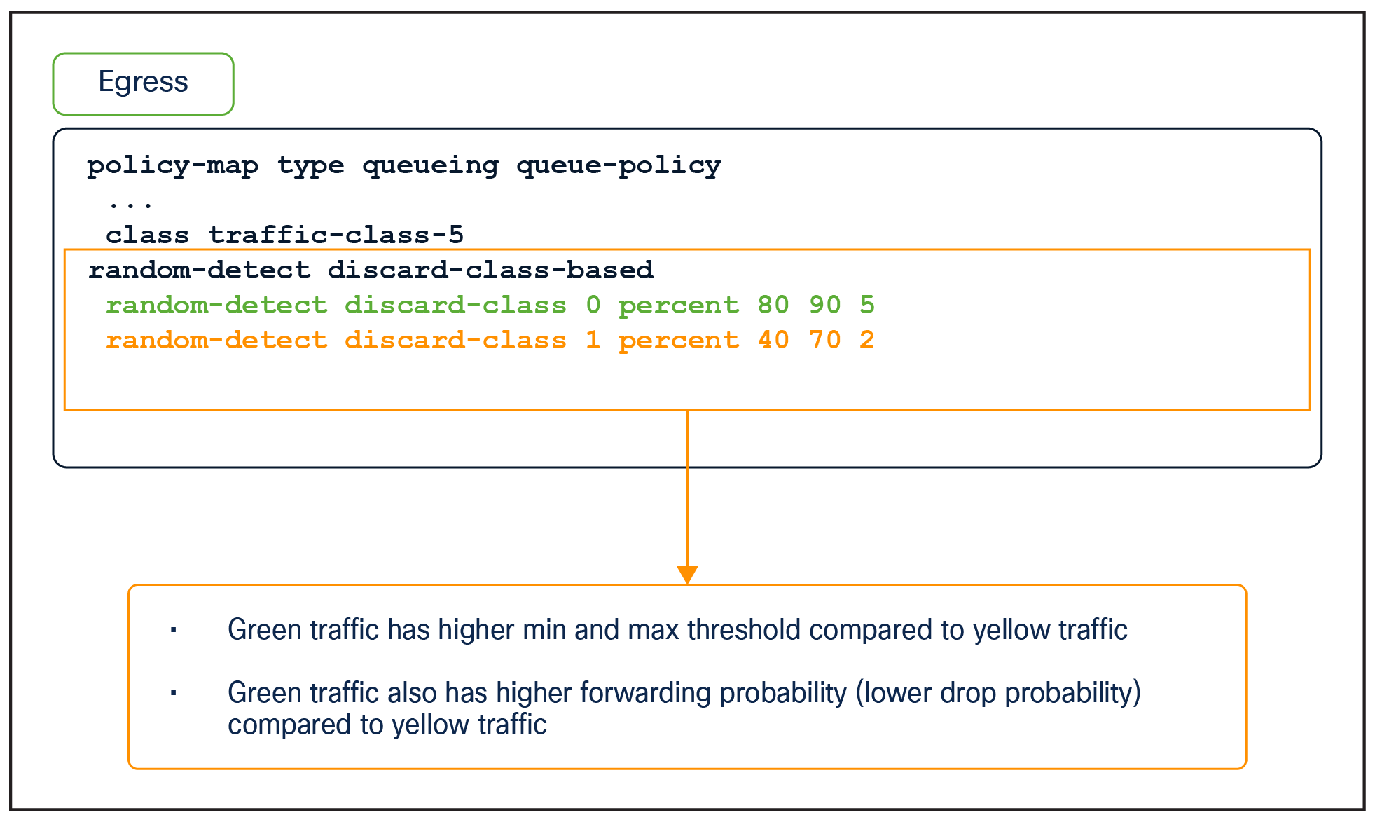
WRED configuration example
Egress marking policy
In addition to the queueing and shaping policy, we can apply a marking policy in the egress direction. The purpose of this policy is to change the QoS tags of the packets going out of the switch. This action occurs after the traffic has been scheduled for egressing out of the switch, and hence this occurs after all VoQ QoS operations are performed.
Egress marking policies cannot match egress traffic using an ACL. Instead, the packet must be matched using an ACL at the ingress and mapped to a QoS group that can be called at the egress direction. DSCP, CoS, IP precedence, MPLS EXP, and QoS group can be matched into the egress marking policy.
On the interface, we can apply two separate policies, one for queueing and one for marking. The configuration below shows how both policies can be applied at the same time on the interface.
interface Hu1/0/1
service-policy type queueing output egress-queueing-policy
service-policy output egress-marking-policy
Hierarchical QoS
Hierarchical QoS (HQoS) is an egress tool that allows two MQC policies to be stacked on two levels (known as parent and child), thus allowing for greater policy granularity. The parent policy is at the top level and the child is at the bottom level. Administrators can use HQoS to allow a parent class to shape multiple queues in a child policy.
Unlike the UADP QoS, where we had multiple configuration options with HQoS, on the Cisco Silicon One only a port shaper configuration is supported.
Port shaper
A port shaper allows a parent class to shape multiple queues in a child policy.
An HQoS port shaper applies a shaper to all egress traffic using the class default. Within this shaped bandwidth, additional child policies can be specified.
The following example demonstrates an HQoS port shaper configuration:
Port Shaper
policy-map PARENT
class class-default
shape average percent 10
service-policy CHILD
policy-map CHILD
class VOICE
priority level 1 percent 20
class C1
bandwidth remaining percent 10
class C2
bandwidth remaining percent 20
class C3
bandwidth remaining percent 70
Notes on port shaper:
● Only the class default can be used in the parent policy.
● Up to seven priority queues are allowed in the child policy.
● Different bandwidth per class is allowed in the child policy.
Sub-interface queueing
Unlike the UADP family, the Cisco Silicon One ASIC supports applying shaping and queueing policies on a sub-interface, in addition to applying a policy on the parent interface.
Applying the policy on the main interface causes all sub-interfaces to use the policy from the main interface. This policy can use all eight VoQs and hence can match up to eight traffic classes. However, none of the eight traffic classes can have priority queueing.
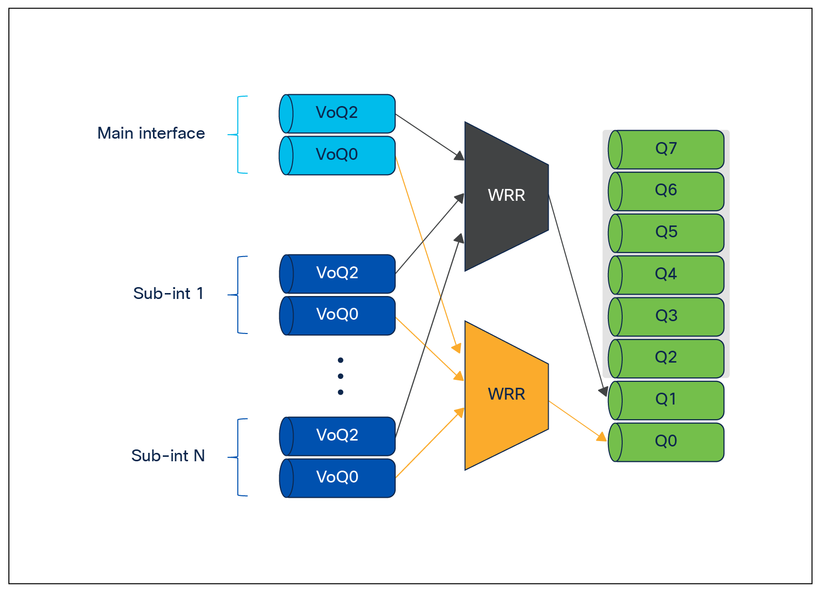
For a more granular policy-map configuration per sub-interface, and to use priority queueing across sub-interfaces, we can apply the policy on the sub-interface instead of the main interface. This feature needs to be enabled using the command queueing mode sub-interface priority propagation under the main interface.
Once this command is applied, each sub-interface can support a maximum of two VoQs (versus eight VoQs on the main physical interface). One of the VoQs can be used for high-priority low-latency packets by configuring as priority level 1. The rules of priority configuration still apply; that is, the priority queue must match traffic class 7. The other VoQ can then be used for rest of the network traffic.
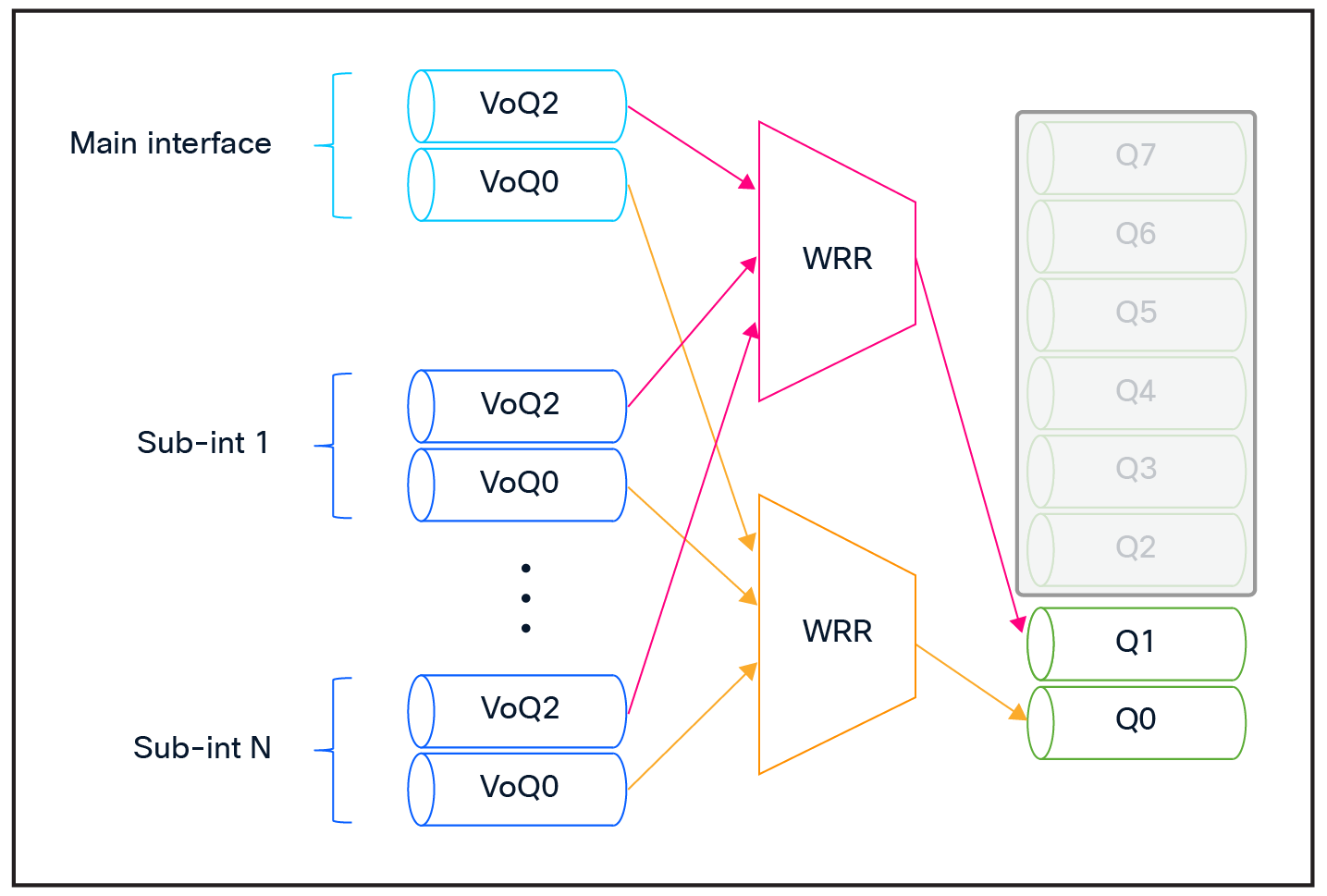
Sub-interface queues
Bandwidth sharing between sub-interfaces can be enabled using the command bandwidth ratio N. This command allows us to specify weights for the WRR algorithm to take into account when servicing the sub-interfaces. An example configuration is given below.
policy-map type queueing SubIntfPmap
class tc7
priority level 1
shape average percent 10
queue-limit 100000000 bytes
class class-default
queue-limit 100000000 bytes
policy-map type queueing SubIntfPortShapePmap
class class-default
bandwidth ratio 4
service-policy SubIntfPmap
!
Under one main interface we can have up to eight unique weights for individual sub-interfaces.
The Cisco Catalyst 9000 switch family has a special set of queues that manage the access to the CPU. This set of queues can ensure that priority packets are received first.
To-CPU incoming packets
Packets destined for the CPU will follow the normal ingress data forwarding path. Depending on the packet destination and type, they will enter one of the CPU queues. Every CPU queue has a predefined policer to protect the CPU. This is commonly referred as control plane policing (CoPP).
From-CPU originated packets
Packets generated by the CPU are sent directly to the egress queues.
When you define a queuing policy on a port, control packets are mapped to a queue with the following order:
● The highest-level nonpriority queue is always chosen first.
● In the absence of the above, queue 0 is selected.
In the second case, where queue 0 is selected, you must assign the highest bandwidth to this queue to get the best QoS treatment for the CPU-generated traffic.
The Cisco Silicon One powered switches in the Cisco Catalyst 9000 family offer flexible techniques to change and adjust the device hardware resources for QoS and queuing. These techniques provide application and user traffic with a wide variety of options to adapt to changes over time.
The following websites offer more detailed information about the Cisco Catalyst 9000 family and its capabilities.