Cisco Catalyst 9500 Series Architecture White Paper
Available Languages
Bias-Free Language
The documentation set for this product strives to use bias-free language. For the purposes of this documentation set, bias-free is defined as language that does not imply discrimination based on age, disability, gender, racial identity, ethnic identity, sexual orientation, socioeconomic status, and intersectionality. Exceptions may be present in the documentation due to language that is hardcoded in the user interfaces of the product software, language used based on RFP documentation, or language that is used by a referenced third-party product. Learn more about how Cisco is using Inclusive Language.
Enterprise campus networks are undergoing profound changes to support ever-increasing bandwidth demands on the access layer with the introduction of 802.11ax and rapid growth of powerful endpoints. With access layer bandwidth moving from 1-Gbps to 2.5-Gbps and 5-Gbps speeds, higher bandwidth like 25 Gbps, 40 Gbps, 100 Gbps, and 400 Gbps will become the de facto speeds to maintain a similar oversubscription ratio.
Cisco Catalyst® 9500 Series Switches are the foundation of the Cisco® next-generation, enterprise-class backbone solutions. These switches are industry’s first purpose-built, fixed 1-Rack-Unit (RU) core and aggregation layer switches targeted for the enterprise campus. These switches deliver exceptional table scales (MAC, IP route, and Access Control List [ACL]) and packet buffering capabilities for enterprise applications. This platform delivers up to 12 terabits per second (Tbps) of switching capacity and up to 8 billion packets per second (Bpps) of forwarding performance.
The platform offers nonblocking 400 Gigabit Ethernet (GE) Quad Small Form-Factor Pluggable Double Density (QSFP-DD), 100 GE Quad Small Form-Factor Pluggable 28 (QSFP28) and 40 GE Quad Small Form-Factor Pluggable (QSFP+) as well as 25 GE Small Form-Factor Pluggable 28 (SFP28) and 10/1 GE Small Form-Factor Pluggable (SFP+/SFP) switches with granular port densities that meet diverse campus needs.
This white paper provides an architectural overview of the switches in the Cisco Catalyst 9500 Series, including system design, power, cooling, and storage options.
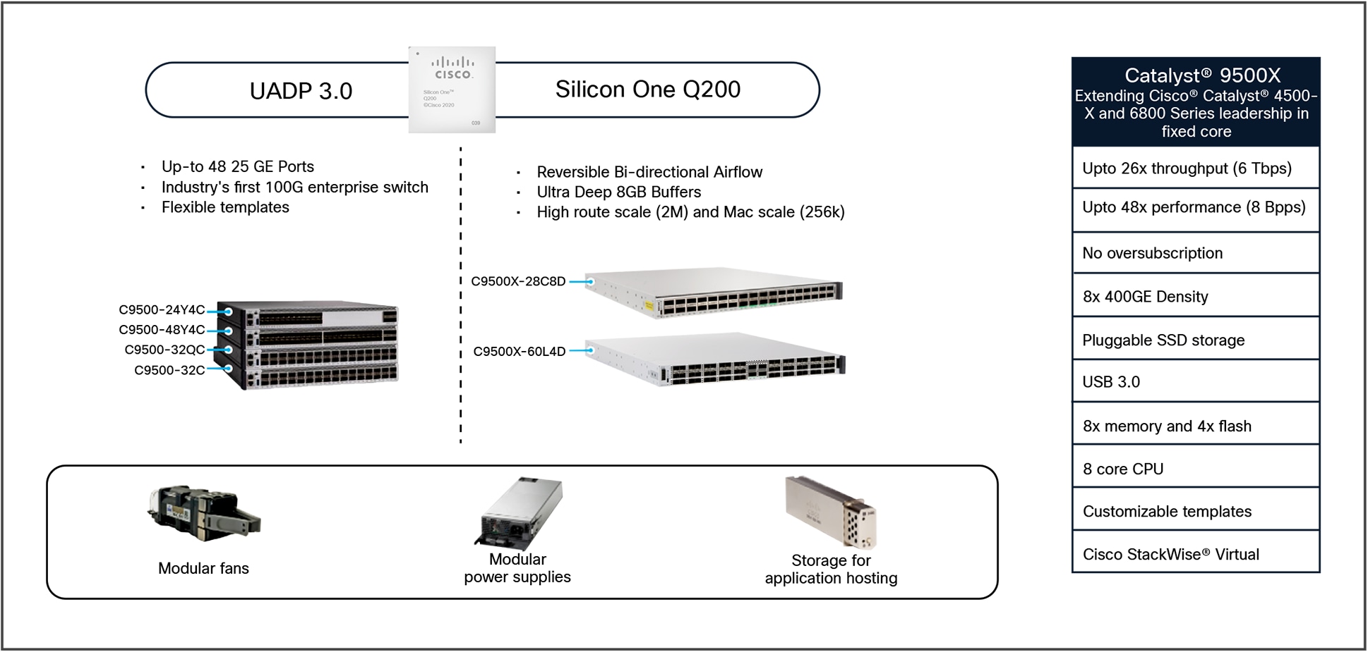
The Cisco Catalyst 9500 platform consists of fixed-configuration, front-to-back airflow (and reversible airflow supported on Catalyst 9500X) switches built on either the Cisco Silicon One™ Q200 application-specific integrated circuit (ASIC) or the Cisco Unified Access™ Data Plane (UADP) 2.0XL or 3.0 ASIC. The platform runs on the modern open Cisco IOS® XE operating system, which supports model- driven programmability and has the capacity to host containers and run third-party applications natively within the switch (by virtue of an x86 CPU architecture, local storage, and a higher memory footprint).
The platform also supports a variety of hardware high-availability capabilities, including Platinum-rated dual-redundant power supplies and variable-speed, high-efficiency redundant fans. The Cisco Catalyst 9500 Series (Figure 1) offers switches with multiple port speeds and port densities for the ever-increasing performance demands within enterprise campus environments.
Cisco Catalyst 9500 Series Switches
Cisco Catalyst 9500X switch
The Catalyst 9500X switch provides high link speeds and increased buffers built with the Cisco Silicon One Q200 ASIC, which supports a maximum forwarding capacity of 6 Tbps (12 Tbps full duplex) per ASIC with much larger table scale compared to the high-performance UADP 3.0-based Catalyst 9500 SKUs. The flexibility of the Cisco IOS XE operating system allows the introduction of a new ASIC with VoQ forwarding engine, while still running on the same binary image used for all other 9500 Series switches.
400 GE switches:
● C9500X-28C8D – Catalyst 9500X switch includes 1x Cisco Silicon One Q200 ASIC with 28x 100 GE QSFP28 ports and 8 x 400 GE QSFP-DD ports.
● C9500X-60L4D – Catalyst 9500X switch includes 1x Cisco Silicon One Q200 ASIC with 60 SFP56 x 10/25/50G ports and 4 x 400 GE QSFP-DD ports.
Cisco Catalyst 9500 series switches
The Catalyst 9500 Series provides an architectural foundation for next-generation hardware features and scalability. These high-performance switches are based on the UADP 3.0 ASIC, which supports a maximum forwarding capacity of 3.2 Tbps per ASIC and allows large table scale.
100 GE switches:
● C9500-32C – Catalyst 9500 high-performance switch includes 2x UADP 3.0 ASICs with 32x 100 GE QSFP28 ports.
● C9500-32QC – Catalyst 9500 high-performance switch includes 1x UADP 3.0 ASIC with 32x 40 GE or 16x 100 GE QSFP28 ports.
25 GE switches:
● C9500-48Y4C – Catalyst 9500 high-performance switch includes 1x UADP 3.0 ASIC with 48x 25 GE SFP28 and 4x 100/40 GE QSFP28 ports.
● C9500-24Y4C – Catalyst 9500 high-performance switch includes 1x UADP 3.0 ASIC with 24x 25 GE SFP28 and 4x 100/40 GE QSFP28 ports.
Note: Naming suffix conventions on the Catalyst 9500 Series indicate supported port speeds:
● C9500/C9500X: Represents ASIC type
● Y: 25 GE front-panel ports
● L: 50 GE front-panel ports
● Q: 40 GE front-panel ports
● C: 100 GE front-panel ports
● D: 400 GE front-panel ports
This section describes the high-level highlights of the Catalyst 9500 Series switches. The Catalyst 9500 Series supports:
● Multiple SKU options: Select the system that best fits your needs based on port speeds, port density, and network scale.
● Up to two Platinum-rated power supply units (PSUs): 1.6kW AC/DC or 950W/930W AC/DC or 1.5kW AC/DC power supplies supporting 1:1 power redundancy.
● New highly efficient variable-speed fans: Supports N+1 or 1+1 fan/fan-tray redundancy with maximum fan speed up to 24000 rpm.
● Multi-rate optics: Every QSFP-DD port can support different speeds of 400/100/40/25/10/1 GE1 and every QSFP28 port can support different speeds of 100/40/10/1 GE.1
● Up to 960 GB M2 SATA external SSD storage: Primarily for hosting third-party applications.
With enterprise networks moving toward higher speeds like 100 Gbps and 400 Gbps, reports indicate that modular port shipments are declining as fixed switches offer significant density, cost, and power benefits. This section briefly covers the high-level system design of the new Cisco Catalyst 9500 Series switches. Additional details can be found in the later sections.
Figures 2 through 6 show the different Catalyst 9500 Series board layouts.
C9500X series board layout
C9500-32C board layout
C9500-32QC/48Y4C/24Y4C board layout
The Catalyst 9500 Series switches also include a front-panel RJ-45 console port, USB mini type B or USB-C console port, an RJ-45 management port, and a USB type A 2.0/3.0 host port for flash drives. All switches come with built-in passive RFID for inventory management, Blue Beacon LED for switch-level identification and Tri-Color LED for system status.
The rear panel on the Catalyst 9500 switches has two field-replaceable PSU slots and five field replaceable redundant variable speed fans or dual fan trays units, and an M2 SATA drive or USB 3.0 drive for storage.
The Cisco Catalyst 9500 high-performance switches support up to two 1.6kW/650W AC or 1.6kW/930W DC small form-factor PSUs for a total system capacity of 1.6kW or 650W (Figure 5). The Catalyst 9500 UADP 2.0 XL SKUs support up to two 950W AC/DC PSUs for a total system capacity of 950W. Each PSU is Platinum-rated for greater than 90 percent power efficiency at 100 percent load.
The system supports either one PSU operating in nonredundant mode, which is sufficient to power up the switch in its maximum configuration, or two PSUs operating in redundant load-sharing mode, where 50% power is withdrawn from each PSU. Power supplies support both AC, DC, and a combination of AC and DC units, and support full Online Insertion and Removal (OIR) capabilities.
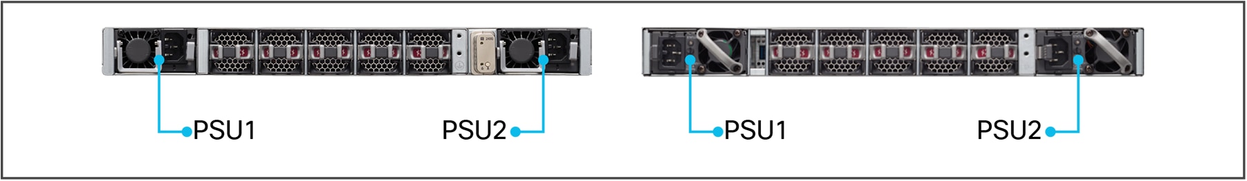
Numbering of Catalyst 9500 Series power supplies
The maximum output power per power supply in the Catalyst 9500 switches is:
● 1.6kW AC PSU is 1.6kW at 220V input and 1000W at 110V input
● 1.5kW AC PSU is 1.5kW at 110-220V
● 950W AC PSU is 950W at 110V-220V
● 930W AC PSU is 930W at 110-220V
Each PSU has a power holdup time of approximately 20 ms at 100 percent load. Each PSU comes with front-to-back variable-speed cooling fans and has a push-release lock for simple and secure OIR. Figure 6 shows the PSU features of the switches.
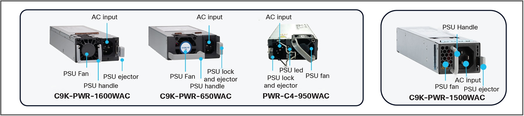
Catalyst 9500 Series AC PSUs
Each PSU supports a bicolor (green/amber) LED to determine the status of the power supply, as shown in Table 1.
Table 1. Catalyst 9500 AC PSU LEDs
| LED |
Color |
Status |
Description |
| Green |
|
Off |
No input power |
| Green |
|
Blinking |
12V main off, 12V standby power ON |
| Green |
|
Solid |
12V main ON |
| Amber |
|
Blinking |
Warning detected, 12V main |
| Amber |
|
Solid |
Critical error detected |
The Catalyst 9500X switches support hot-swappable and field-replaceable variable-speed modular fans (six individual fan modules) in the rear of the switch. The fan modules come in different product IDs for different airflow directions (front to back or back to front) as required. Refer to the airflow section following this for details.
Catalyst 9500 high-performance SKUs support hot-swappable and field-replaceable variable-speed modular fans ((five individual fan modules) in the rear of the switch. Catalyst 9500 UADP 2.0 XL-based SKUs support hot-swappable and field-replaceable variable-speed fan trays (two fan trays with dual-stacked fan modules) in the rear of the switch with front-to-back airflow. These fan and fan-tray units support Online Insertion and Removal (OIR) and can support a maximum fan speed of 24,000 rpm.
The fan unit is responsible for cooling the entire switch and interfacing with environmental monitors to trigger alarms when conditions exceed thresholds. Switches are equipped with on-board thermal sensors to monitor the ambient temperature at various points and report thermal events to the system to adjust the fan speeds. Switches supports a hardware failure of up to one individual fan or fan tray, where remaining fans will automatically increase their rpm to compensate and maintain sufficient cooling. If the switch fails to meet the minimum number of required fans, the switch shuts down automatically to prevent the system from overheating.
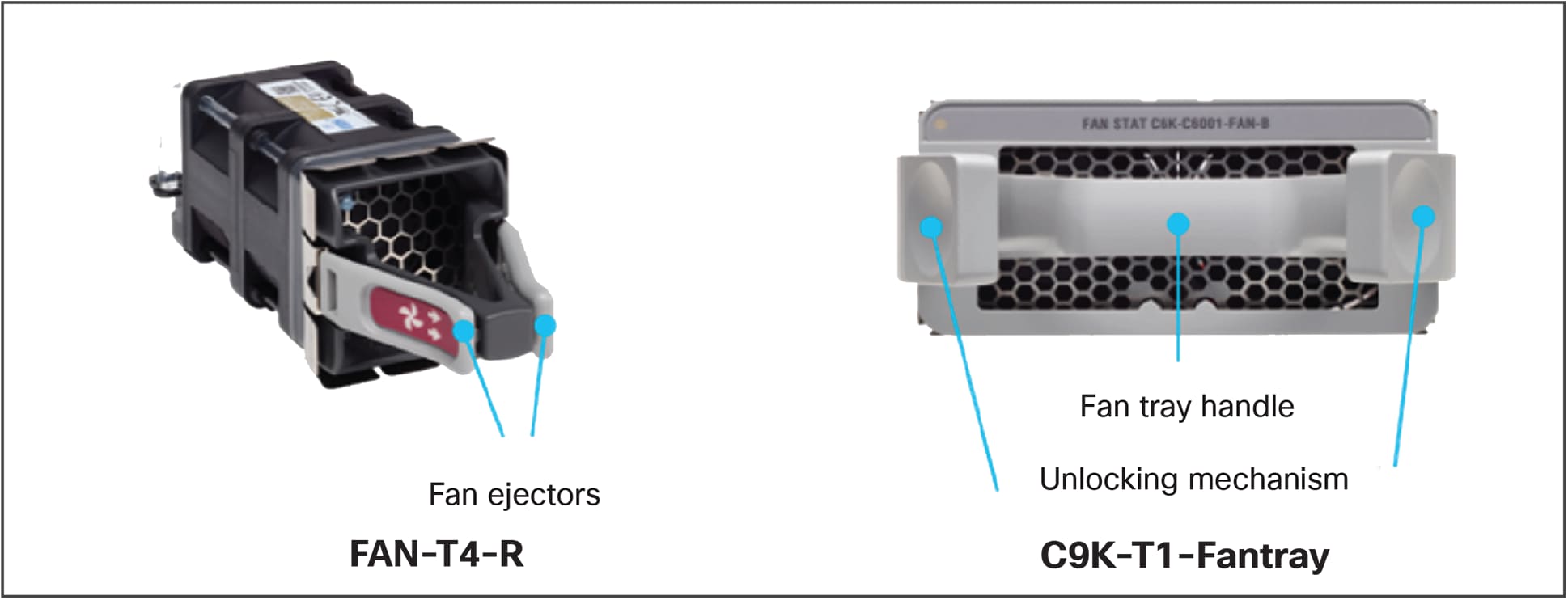
Catalyst 9500 Series fan units and fan trays
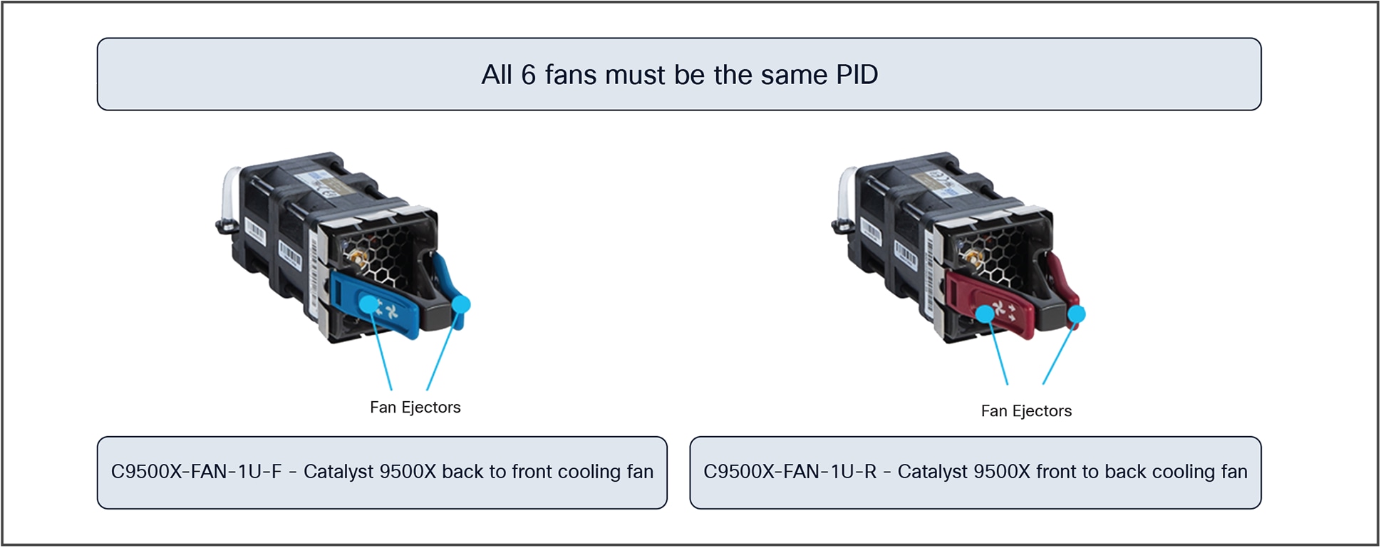
Catalyst 9500X fan units
Insertion and removal of the fan modules are made easy with fan assembly ejectors levers. Press the fan ejector levers and use the fan handle to insert or remove the module. Table 2 highlights the LED signal for each fan and fan tray state.
Table 2. Cisco Catalyst 9500 fan and fan tray LEDs
| LED |
Color |
Status |
Description |
| Fan |
|
Off |
No input power |
| Fan |
|
Blinking |
12V main off, 12V standby power ON |
| Fan |
|
Solid |
Critical error detected |
The Catalyst 9500X-28C8D and 9500X-60L4D models support both front-to-back airflow as well as back-to-front airflow. The power supply fan direction changes based on the direction of the airflow from the fan tray. Airflow is normally defined by the points of air intake vs. air exhaust. The color of the installed fan units helps visually indicate the direction of airflow (intake vs. exhaust):
● Royal blue: Back to front (rear intake, port-side exhaust)
● Burgundy: Front to back (port-side intake, rear exhaust)
The airflow direction and details are illustrated in the Figure 9.
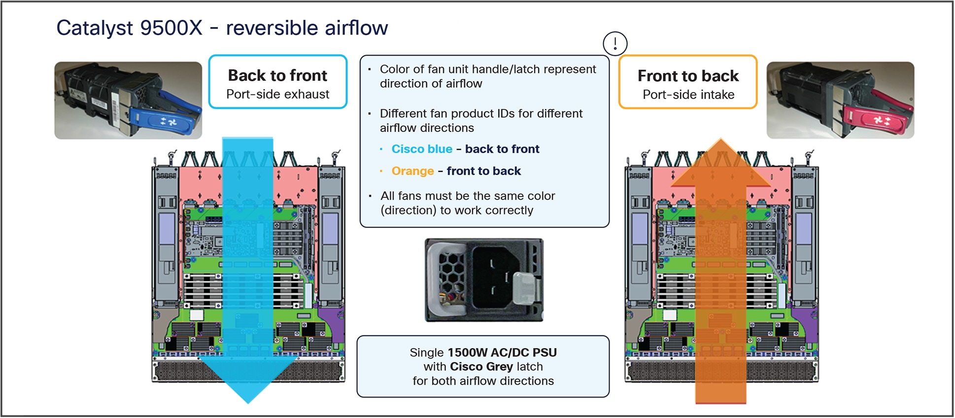
Reversible airflow on the C9500X series
The Catalyst 9500 Series and Catalyst 9500 Series high-performance fans and fan trays support front-to-back airflow. Airflow vents are illustrated in Figure 10.
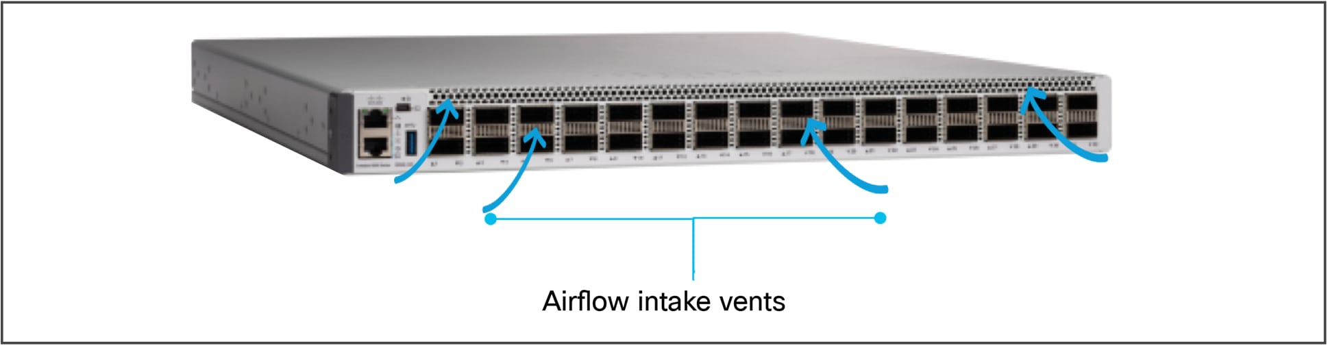
Airflow on the Catalyst 9500 and 9500 high-performance switches
Port-side intake airflow is supported on all C9500 SKUs, where coolant air enters the switch through the port side (cold aisle) and exhausts through the fan and power supply modules in the rear (hot aisle). QSFP/SFP cages are thermally enhanced with the mid-portion allowing airflow through the cage.
Catalyst 9500 switches are line rate switches offering configurable system resources to optimize support for specific features, depending on how the switch is used in the network. The switch architecture consists of five main components:
● ASIC complex
● X86 CPU complex
● ASIC interconnect
● Front-panel interfaces
● 10 GE CPU (KR) ports
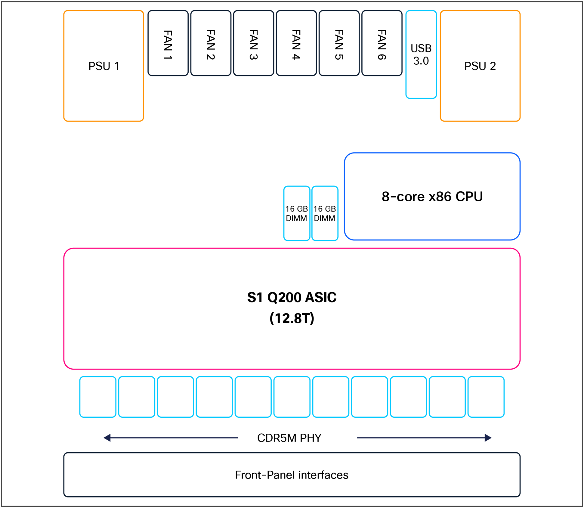
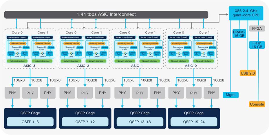
The figure below shows a high-level diagram of the components in the Catalyst 9500X-28C8D switch.
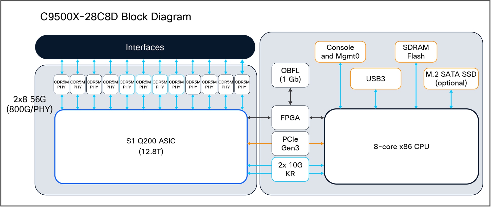
C9500X-28C8D block diagram
Figure 12 shows the high level diagram of the 9500X-60L4D switch.
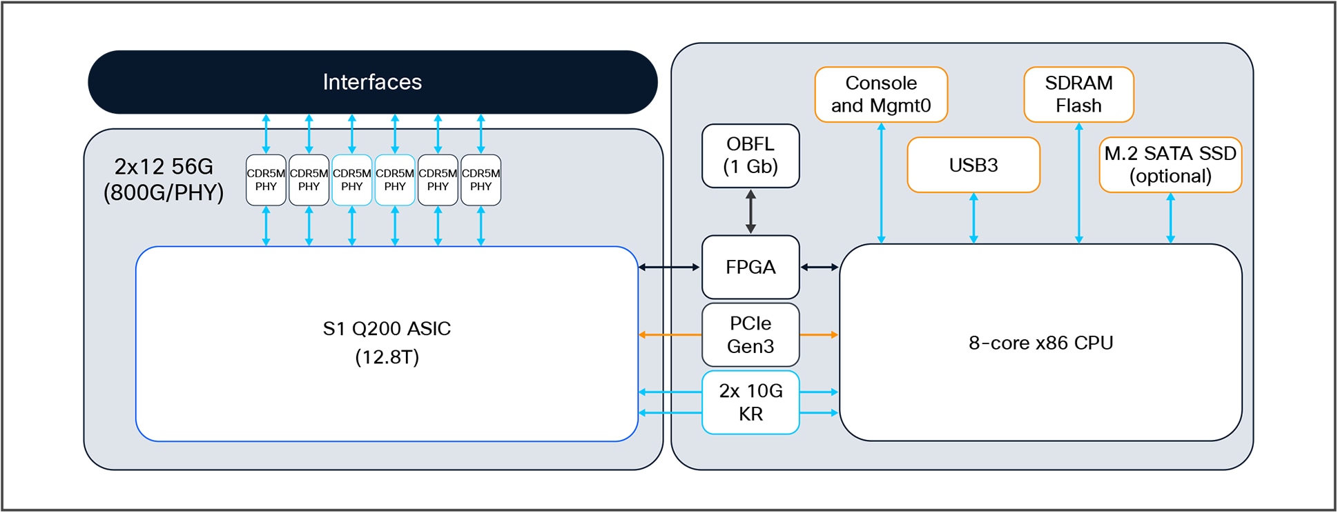
C9500X-60L4D block diagram
Figure 13 shows a high-level diagram of the Catalyst 9500 high-performance components.
Catalyst 9500 high-performance SKU high-level block diagram
Cisco Silicon One ASIC complex
The Catalyst 9500X series is built on the Cisco Silicon One Q200 ASIC. The Q200 ASIC is built using a 7-nm fabrication technology and leverages an innovative, state-of-the-art, multislice architecture, which allows for very high processing performance with a lower power footprint, extremely high switching capability, with very high IP route and MAC scales and extremely deep buffers. Cisco Silicon One ASICs support fully P4 programmable NPL/SDK microcode.
A multislice ASIC design architecture is similar to multicore and multi-ASIC, which combines multiple network processing units (NPUs) onto a single die package, to multiply total capacity. A multislice design is unique because each ASIC NPU (called a “slice”) operates independently, each with full forwarding I/O resources (unlike multicore, which typically shares the same I/O resources), and the slices are connected via an integrated crossbar “fabric.”
Multislice ASICs use an integrated Virtual Output Queue (VOQ) buffer architecture to manage data traffic between slices. Like multicore ASIC design, this approach addresses many of the limits of NPU clock speeds and cooling, while also multiplying overall ASIC throughput.
The following are the key Cisco Silicon One Q200 capabilities.
● Packet bandwidth/switching throughput (full duplex): 12.8 Tbps
● Forwarding performance (6 slices): 8 Bpps
● Forwarding Info Base (FIB) entries: Up to 10M IPv4 or 5M IPv6 routes
● Low-latency packet buffer: 80 MB of Shared Memory System (SMS)
● Unified deep packet buffer: Up to 8 GB of High Bandwidth Memory (HBM)
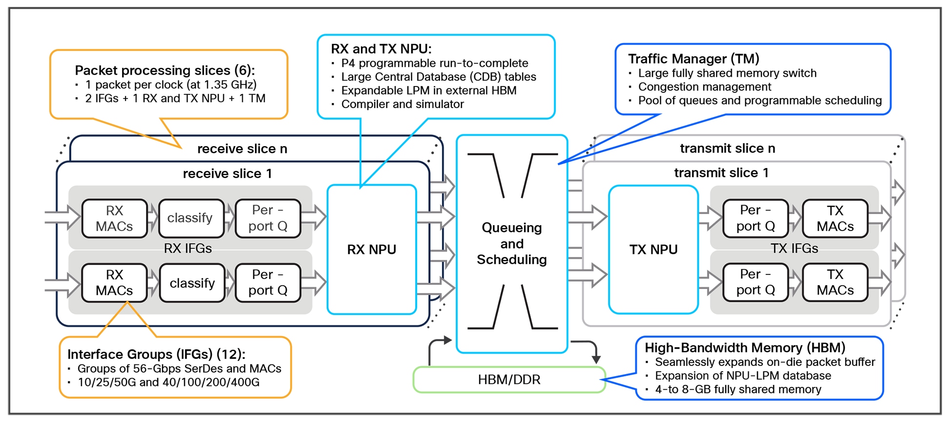
Slice architecture of the Catalyst C9500X-28C8D
Catalyst 9500 Series Switches are built on two variants of the UADP ASIC: UADP 2.0 XL and UADP 3.0. Both are based on a programmable System-On-Chip (SOC) architecture. The architecture of both ASICs is similar, but the versions differ in switching capacity, port density, port speeds, buffering capability, and forwarding scalability.
The UADP 3.0 ASIC is based on the UADP 2.0 architecture, using a 16-nm technology that offers significantly larger tables and bandwidth, up to 1.6 Tbps, compared to all other UADP ASICs.
Figure 15 shows the components of the UADP 3.0 ASIC.
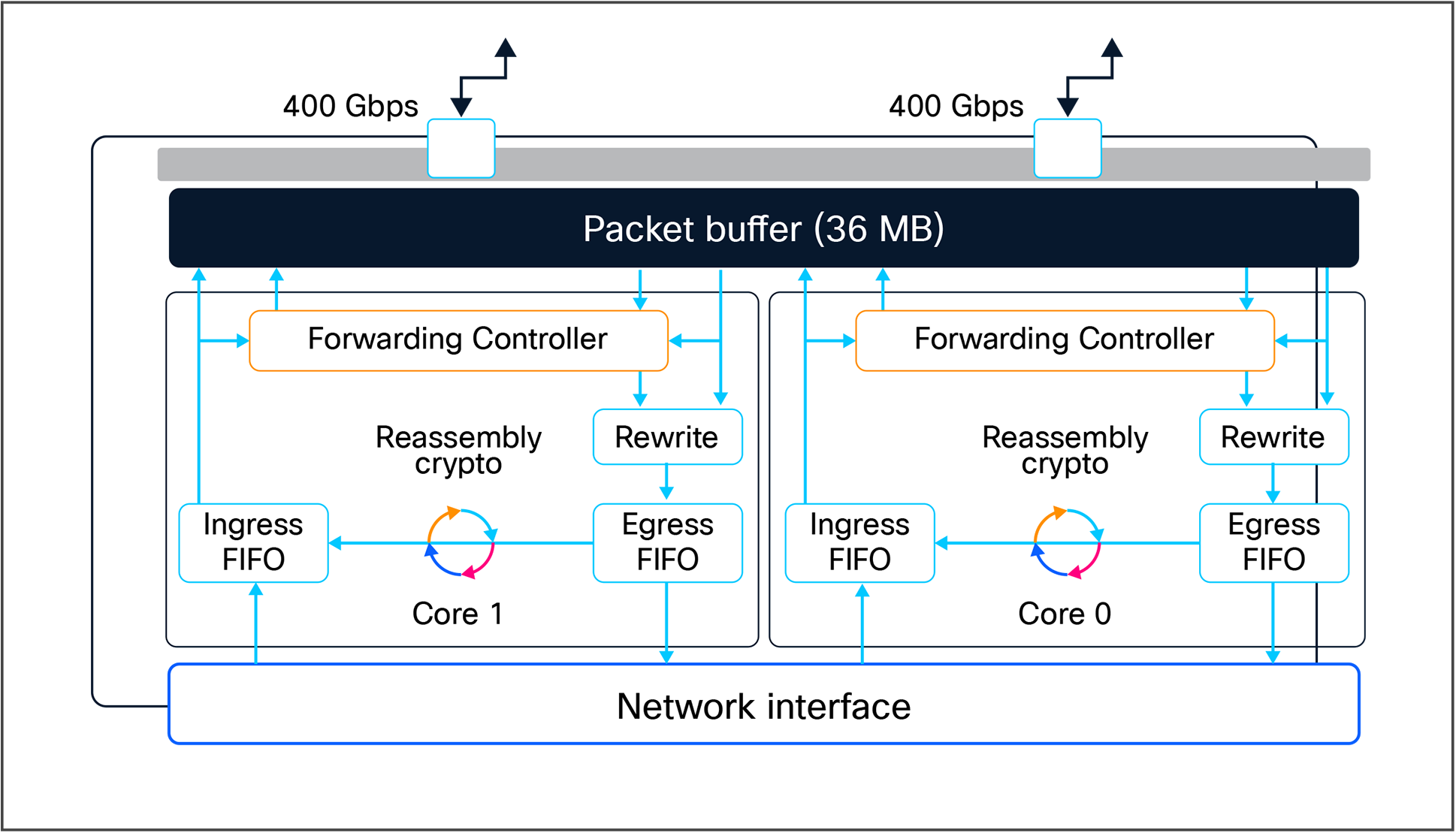
UADP 3.0 ASIC block diagram
Key Cisco UADP 3.0 capacities and capabilities include:
● Packet bandwidth/switching throughput (full-duplex): 1.6 Tbps (800 Gbps per core)
● Forwarding performance (2 cores): 1 Bpps (500 Mpps per core)
● ASIC interconnects: Two point-to-point links with total of 800 Gbps bandwidth
● Forwarding Info Base (FIB) entries: 416,000 double-width tables (IP4v/IPv6)
● Unified packet buffer: 36 MB (shared between both cores)
● NetFlow: Up to 128,000 IPv4/IPv6 double-width shared tables
● TCAM ACL: 54,000 total capacity
Note: The UADP 3.0 ASICs achieve line-rate forwarding performance for packet sizes greater than 187 bytes and above. The Cisco Silicon One Q200 ASIC achieves line-rate forwarding for packet sizes greater than 256 bytes and above.
Table 3 highlights the high-level differences between the UADP 3.0, and Silicon One Q200 ASICs.
Table 3. Catalyst 9500 ASIC comparison
| Capabilities (per ASIC) |
Catalyst 9500 High Performance (UADP 3.0) |
Catalyst 9500X series (Silicon One Q200) |
| Switching and forwarding capacity |
3.2 Tbps/1 Bpps |
6 Tbps/8 Bpps |
| Stack bandwidth |
2x 400 Gbps |
– |
| Buffer capability |
36 MB shared buffer |
80 MB shared buffer – |
| Switch Database Management |
Customizable templates |
Customizable templates |
| NetFlow capabilities |
Shared NetFlow table |
Sampled NetFlow (1:1000) |
| v4 FIB scale |
Up to 416,000* |
Up to 2M |
| v4 and v6 scale |
v4 and v6 same scale |
v6 reduced by half |
Catalyst 9500 Series Switches are equipped with an Intel multicore X86 CPU, system memory, and flash storage.
Some CPU highlights include:
● 2.4 GHz x86 4-core CPU for Catalyst 9500 and 9500 high performance Series (Intel® Xeon®-D CPU)
● 2.4 GHz x86 8-core CPU for Catalyst 9500X-28C8D switch (Intel Xeon-D NS CPU)
● Dual 16 GB (total 32 GB) of DDR4 2400MT/s RAM for Catalyst 9500X-28C8D switch.
● Single 16 GB of DDR4 2400MT/s RAM for Catalyst 9500 and 9500 high performance series
● Support for a USB Type A file system (front-serviceable) for external storage and Bluetooth dongle
● Support for a USB Type B or USB-C serial console in addition to an RJ-45 serial console
● 16 GB of internal enhanced USB (eUSB) flash
● USB 3.0 (400 MB/s read, and 140 MB/s write) or M.2 (300 MB/s read, or 290 MB/s write) form-factor SSD module (rear-serviceable) for application hosting or general-purpose storage
● System reset switch for manual power cycle
Figure 16 outlines the X86 CPU complex.
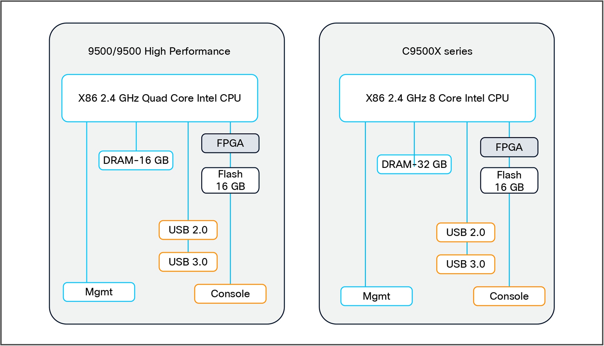
X86 CPU complex
Note: The Catalyst 9500X-28C8D and C9500X-60L4D are based on a single Q200 ASIC, and there is no ASIC interconnect.
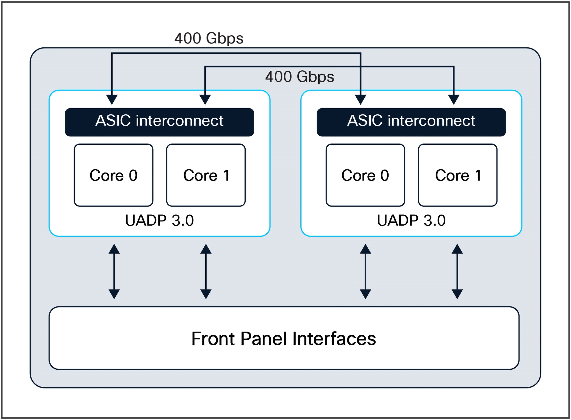
The Catalyst 9500 Series and 9500 high-performance switches are fixed core switches without any rear stack ports. Hence ASIC interconnect links are used for inter-ASIC communications. The purpose of the ASIC interconnects is to move data between multiple UADP ASICs. Communication within a core or between cores is locally switched within the ASIC, so packets destined to local ports within the ASIC do not use an ASIC interconnect link.
UADP 3.0 has two ASIC interconnect links, allowing a total packet bandwidth of 800 Gbps.
ASIC interconnects are a combination of up to 16 SERDES (serializer/deserializer) operating at a 25G NRZ format with a total packet bandwidth of 400 Gbps. Because the UADP 3.0 has two ASIC interconnect links, it allows for a total packet bandwidth of 800 Gbps.
Major UADP 3.0 ASIC interconnect features:
● No packet size limitations
● Packet type-agnostic
● Packet data is spread across the SERDES channels
● Header compression capabilities
● No fragmentation or reordering
● No buffering on ASIC Interconnects links
Figure 17 shows a block diagram of the ASIC interconnect.
Catalyst 9500 high-performance switch ASIC interconnect block diagram
UADP 2.0 XL has effective bandwidth of 720 Gbps, with each core ASIC interconnect burst up to 360 Gbps. 360 Gbps is composed of six dual-independent 60-Gbps rings (see Figure 18).
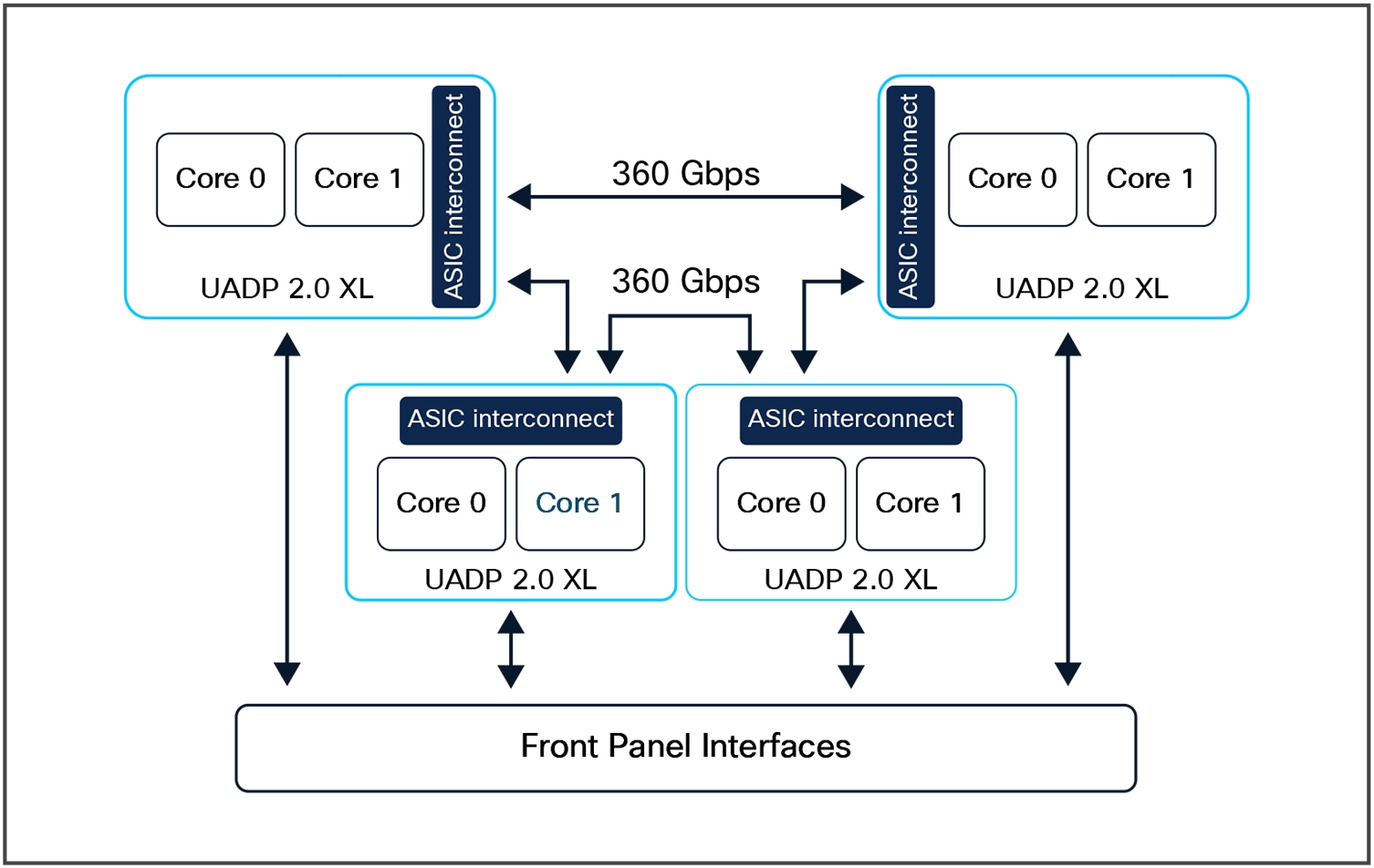
Catalyst 9500 switch ASIC interconnect block diagram
The Ethernet Physical Layer (PHY) connects a link-layer device (often a MAC) to a physical medium such as a transceiver (for example, converting electrical signals to optical signals). The PHY on the Catalyst 9500 switches is a fully integrated Ethernet transceiver supporting steering and mapping of lanes back to the ASIC to support multiple speeds (10, 25, 40, 100, and 400 GE), depending on the optics inserted into the front-panel ports.
Figure 19 provides a high-level overview of the C9500X-28C8D switch front-panel interfaces.
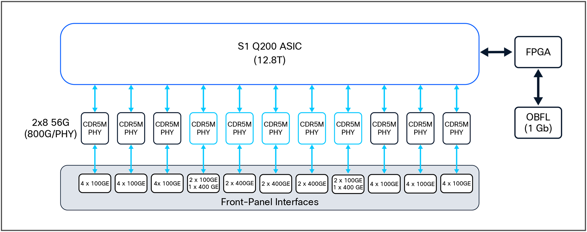
Front-panel layout of the C9500X-28C8D
Highlights of the C9500X-28C8D switch include:
● 28 QSFP28 Ethernet ports
◦ 40 GE or 100 GE with a QSFP+/QSFP28 transceiver, or 10 GE with a CVR adapter
◦ 8 QSFP-DD Ethernet ports
◦ 40/100/200 GE or 400 GE with a QSFP/QSFP28/QSFP-DD transceiver, or 10 GE with a CVR adapter
Port mapping
● All ports mapped to the same ASIC using a multislice design.
● CDR5M PHY supports for MACsec and WAN-MACsec at line-rate.
● 11 CDR5M PHY connecting to the QSFP28 and QSFP-DD front panel ports .
◦ Power to the optics is enabled by the onboard controller, which turns on as the module are inserted into the front-panel cage.
Figure 20 provides a high-level overview of the C9500X-60L4D switch components
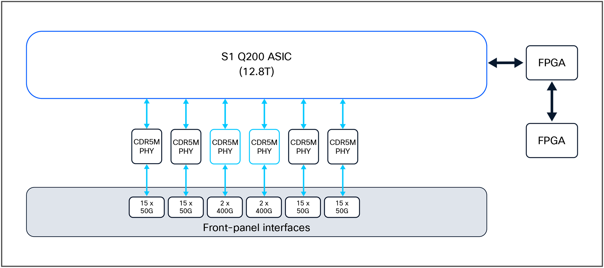
Front-panel layout of the C9500X-60L4D
Highlights of the C9500X-60L4D switch include:
● 60 SFP56 Ethernet ports
◦ 10/25/50G with SFP56 transceivers
◦ 1 GE with special SFP-1G-LH/SX transceiver (max of 8 ports per switch)
● 8 QSFP-DD Ethernet ports
◦ 40/100/200 GE or 400 GE with a QSFP/QSFP28/QSFP-DD transceiver, or 10 GE with a CVR adapter
Port mapping
● All ports mapped to the same ASIC using a multislice design.
● CDR5M PHY supports MACsec, WAN-MACsec at line-rate and provides hardware support for IPSec at 800Gbps.
● 5 CDR5M PHY connecting to the SFP56 and QSFP-DD front panel ports .
◦ Power to the optics is enabled by the onboard controller, which turns on as the modules are inserted into the front-panel cage.
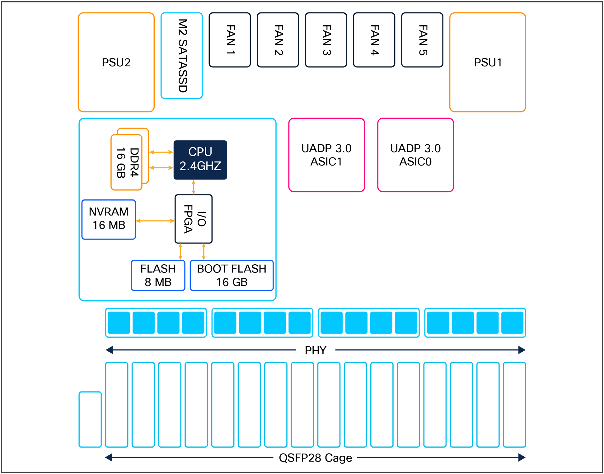
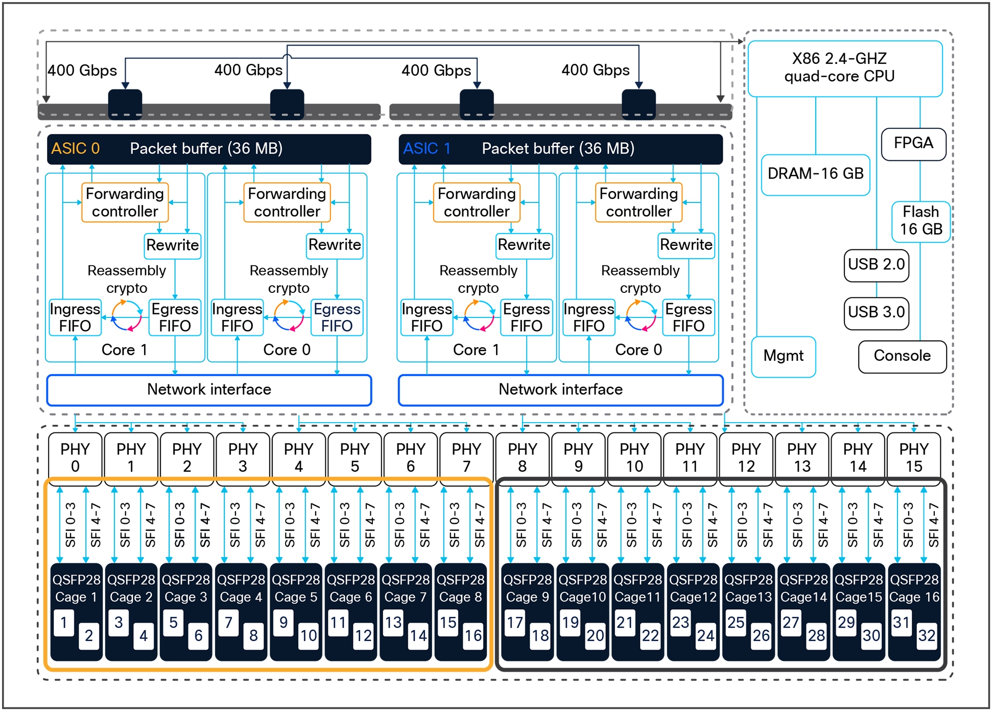
Figure 21 provides a high-level overview of the C9500-32C switch components.
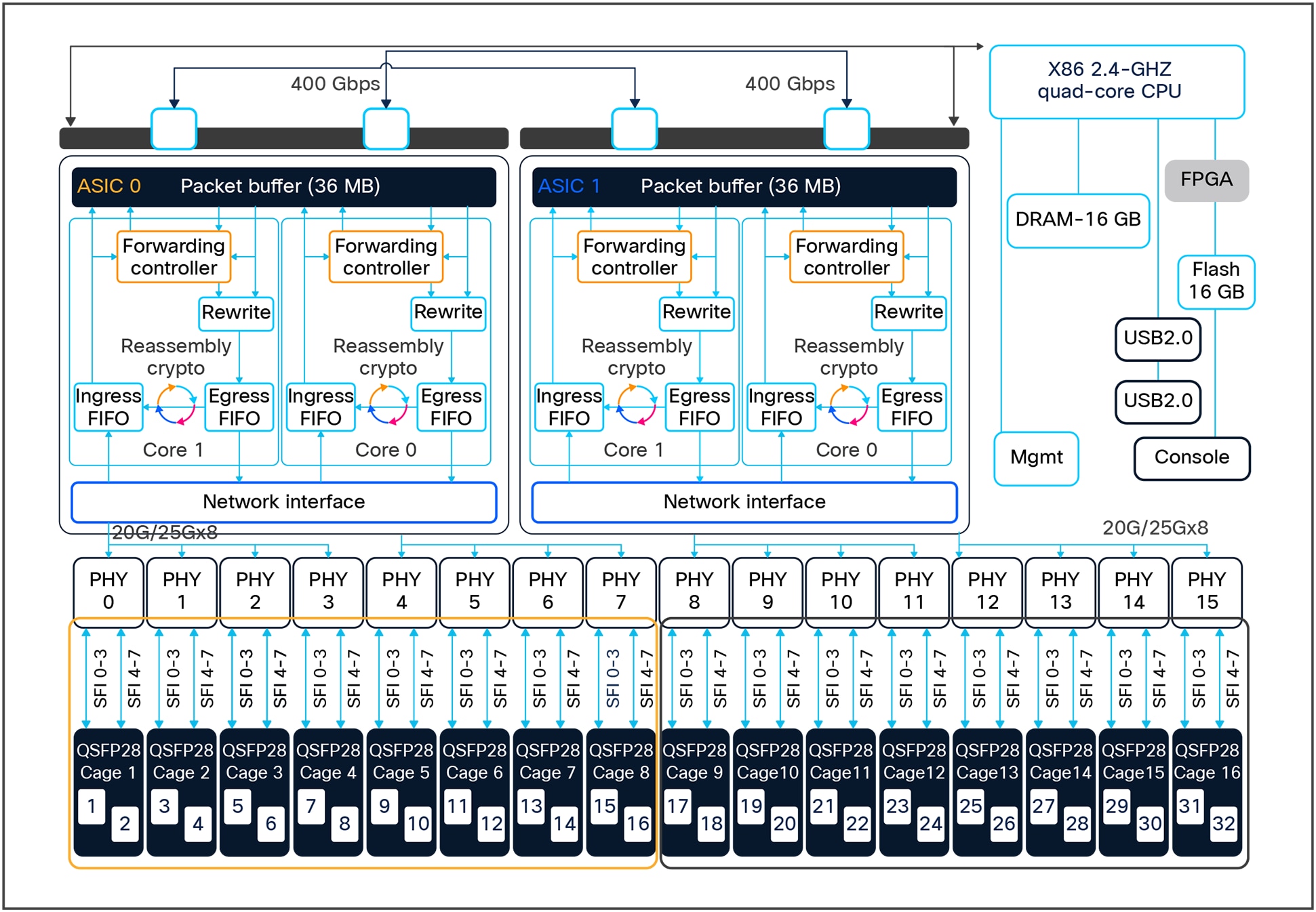
C9500-32C high-level block diagram
Highlights of the C9500-32C switch include:
● 16 columns of QSFP28 cage in 2x1 configuration mode.
● Each QSFP28 cage has eight northbound SERDES connections back to the ASIC.
◦ Each SERDES connection operates at either 4x 10 GE speed for 40 GE QSFP+ optics, or 4x 25 G speed for 100 GE QSPF28 optics.
◦ Interface speeds are based on the transceiver module inserted.
● 32 QSFP28 Ethernet ports.
◦ 40 GE or 100 GE with a QSFP+/QSFP28 transceiver module or 10/1 GE with a CVR adapter.
● Port mapping
◦ Ports 1 to 8 are mapped to ASIC0/Core1 and ports 9 to 16 are mapped to ASIC0/Core0.
◦ Ports 17 to 24 are mapped to ASIC1/Core1 and ports 25 to 32 are mapped to ASIC1/Core0.
● Power to the optics is enabled by the onboard controller, which turns on as the module are inserted into the front- panel cage.
● The advanced-forwarding ASIC supports 100-Gbps single-flow traffic processing on all ports.
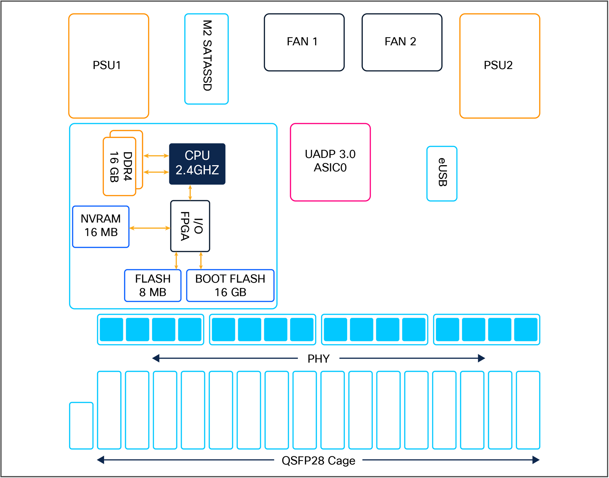
Figure 22 provides a high-level overview of the C9500-32QC switch components.
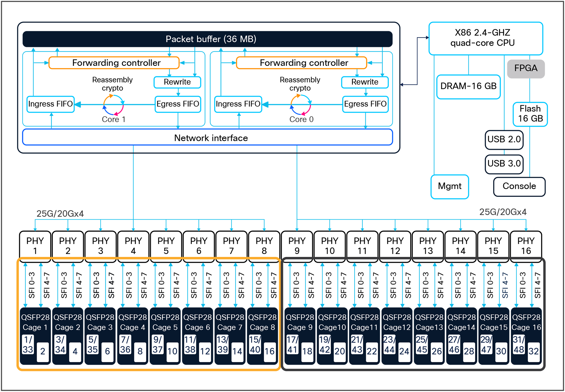
C9500-32QC high-level block diagram
Key highlights of the C9500-32QC switch include:
● 16 columns QSFP28 cage in 2x1 configuration mode.
● Each QSFP cage has four northbound SERDES connections back to the ASIC.
◦ Each SERDES connection operates at either 2x 20 GE speed for 40 GE QSFP+ optics, or 4x 25 GE speed for 100 GE QSPF28 optics.
◦ Interface speeds are CLI-based.
● 32 QSFP28 Ethernet ports
◦ 40 GE or 100 GE with a QSFP+/QSFP28 transceiver module or 10/1 GE with a CVR adapter.
● Port mapping
◦ Ports 1 to 16 are mapped to ASIC0/Core1 and ports 17 to 32 are mapped to ASIC0/Core0.
● Power to the optics is enabled by the onboard controller, which turns on as the module is inserted.
● Default port configuration
◦ Ports 1 to 24 are enabled and active as 40 GE interfaces.
◦ Ports 25 to 32 are 40 GE interfaces but inactive.
◦ Ports 33 to 44 are 100 GE but inactive.
◦ Ports 45 to 48 are 100 GE interfaces and active.
● Enable or disable 100 GE ports using the “enable/no enable” interface command.
● The advanced-forwarding ASIC supports 100-Gbps single-flow traffic processing on 100 GE capable ports and 20-Gbps single-flow traffic processing on all 40 GE ports.
Figure 23 shows the port configuration modes supported on the C9500-32QC switch.
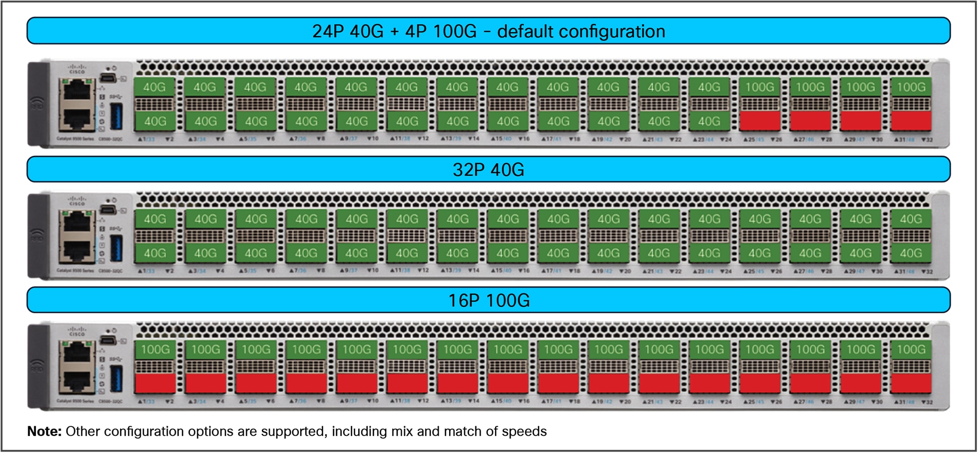
C9500-32QC port configuration modes
Figure 24 provides a high-level overview of the C9500-48Y4C switch components.
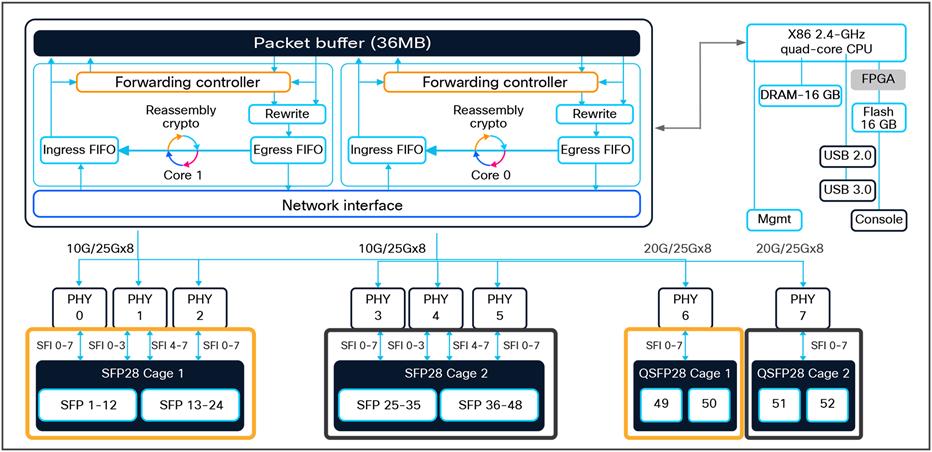
C9500-48Y4C high-level block diagram
Key highlights of the C9500-48Y4C include:
● 12 columns of SFP28 cage in 2x1 configuration mode and 2 columns of QSFP28 cage in 2x1 configuration mode.
● Each SFP28 cage has 24 northbound SERDES connections back to the ASIC.
◦ Each SERDES connection operates at 25 GE speed for SFP28 optic and 10 GE speed for SFP+ optic.
◦ Interface speeds are based on the transceiver module inserted.
● Each QSFP28 cage has eight northbound SERDES connections back to the ASIC.
◦ Each SERDES connection operates at 4x 10 GE speed for 40 GE, or 4x 25 GE speed for 100 GE optics.
● 48 SFP28 Ethernet ports and 4 QSFP28 Ethernet ports.
◦ 25/10/1 GE with a SFP28/SFP+ transceiver module and 40 GE or 100 GE with a QSFP+/QSFP28 transceiver module.
◦ Port mapping for HW versions lower than 4 (check in the output of show module)Ports 1 to 24 and 49 to 50 are mapped to ASIC0/Core1.
◦ Ports 25 to 48 and 51 to 52 are mapped to ASIC0/Core0.
● Port mapping for HW versions greater than 4 (check in the output of show module)
◦ Ports 1 to 32 are mapped to ASIC0/Core1
◦ Port 33 to 48 and uplink ports 49 to 52 are mapped to ASIC0/Core0
● Power to the optics is enabled by an onboard controller, which turns on as the module is inserted.
● The advanced-forwarding ASIC supports 100-Gbps single-flow traffic processing on the uplink ports and 25-Gbps single-flow traffic processing on the downlink ports.
Note: The C9500-24Y4C switch has the exact same architecture as the C9500-48Y4C with 1x UADP 3.0 ASIC and total of 24x 25/10/1 GE ports and 4x QSFP28 Ethernet uplink ports with similar port mapping.
Applications are used in enterprise networks for a variety of business-relevant use cases. Examples of enterprise applications include administrative tools such as performance monitors and protocol analyzers, as well as security toolsets such as intrusion detection services, which traditionally operate on an external physical or virtual server.
This section specifies the SSD modules supported on Catalyst 9500 switches with primary application for hosting third-party applications. The modules also serve as general-purpose storage for packet captures, operating system trace logs, and Graceful Insertion and Removal (GIR) snapshots. Catalyst 9500 switches use a Cisco application framework, also known as Cisco IOx (the application framework combines Cisco IOS and Linux) to support applications containerized in KVM-based virtual machines, Linux Containers (LXC), or Docker containers.
Cisco IOS XE running on the Catalyst 9500 switches reserves dedicated memory and CPU resources for application hosting (Table 4). By reserving memory and CPU resources, the switch provides a separate execution space for user applications, it protects the switch’s IOS XE run-time processes, ensuring both its integrity and performance.
Table 4. Catalyst 9500 application hosting resources
| Platform |
Memory (GB) |
CPU (cores) |
App-Gig ports |
USB 3.0 (GB) |
M2 SATA (GB) |
| Catalyst 9500 high performance (UADP 3.0) |
8 |
1 x 2.4 GHz |
1 |
– |
240/480/960 |
| Catalyst 9500X series |
8 |
1 x 2.4 GHz |
2 |
– |
240/48/960 |
Storage needs on Catalyst 9500 high-performance switches are supported by a pluggable Serial Advanced Technology Attachment (SATA) SSD module located on the rear panel of the switch. This module is a field- replaceable unit and has a hot-swap button on the storage panel of the switch for graceful removal. The SSD module storage capacity ranges are 240GB, 480GB, and 960GB and the default file system supported is EXT4. The SATA module also supports the ability to monitor the health of the device through S.M.A.R.T.
Catalyst 9500X switches also support a pluggable SATA SSD module located on the rear panel of the switch. This module is unique to the 9500X switches and is a field-replaceable unit, with a hot-swap button on the storage panel of the switch for graceful removal.
Figure 25 outlines the Catalyst 9500 Series’ storage options.
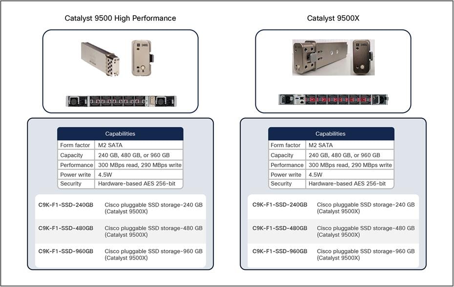
Catalyst 9500 storage options
This section provides a high-level overview of how packet forwarding is performed on a Catalyst 9500X series switches and the Catalyst 9500 high-performance switches.
Catalyst 9500 high performance (UADP 3.0) – unicast forwarding
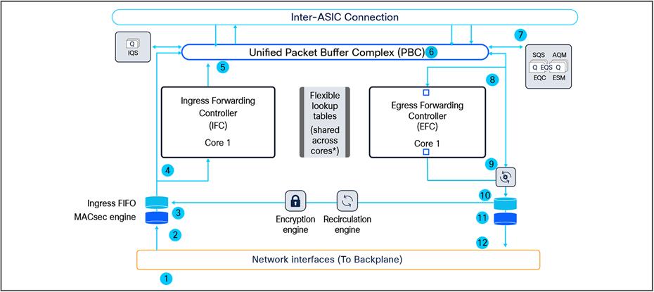
Ingress and egress unicast forwarding with the ASIC
Figure 26 shows a visual representation of the unicast packet forwarding within the ASIC.
Catalyst 9500 high-performance packet walk within the ASIC
Following is the basic sequence of events when packets enter the Catalyst 9500 front-panel ports:
1. Packet arrives at the line card’s ingress port; PHY converts the signal and serializes the bits, and then sends the packet to the Network Interface (NIF) that goes to the backplane.
2. The packet travels through the backplane and enters the NIF of one of the ASICs.
3. The NIF passes the packet to the ingress MACsec engine. The MACsec engine will decrypt the packet if needed. The decryption is done at line rate. The packet now enters the Ingress First In First Out (FIFO).
4. The Ingress FIFO sends the packet to both the Ingress Forwarding Controller (IFC) and the Packet Buffer Complex (PBC) in parallel.
5. The IFC performs Layer 2, Layer 3, Access Control List (ACL), and Quality-of-Service (QoS) lookups and more, then returns the forwarding result (frame descriptor header) to the PBC.
6. The PBC uses the frame descriptor to determine the egress port. As the egress port is on the same ASIC, the result is sent to the Egress Queueing System (EQS) on the same ASIC.
7. The EQS receives the notification from the PBC and schedules the packet to be sent for egress processing.
8. The EQS signals the PBC to send the packet and descriptor out to both the Egress Forwarding Controller (EFC) and the Rewrite Engine (RWE).
9. The EFC completes egress functions and sends the final rewrite descriptor to the RWE.
10. The RWE performs packet rewrite with the final descriptor and sends the packet to the Egress FIFO.
11. The Egress FIFO sends the packet to the Egress MACsec.
12. The Egress MACsec performs a wire-rate encryption if required and then passes the frame on to the NIF. The packet then goes through the backplane and is sent out from one of the line card ports.
Ingress and egress unicast forwarding across the ASIC
Figure 27 shows a visual representation of the unicast packet forwarding across the ASIC.
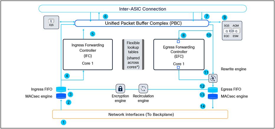
Catalyst 9500 high-performance packet walk across the ASIC
Following is the basic sequence of events when packets enter the Catalyst 9500 front-panel ports:
1. Packet arrives at the line card’s ingress port; PHY converts the signal and serializes the bits and then sends the packet to the Network Interface (NIF) that goes to the backplane.
2. The packet travels through the backplane and enters the NIF of one of the ASICs.
3. The NIF passes the packet to the ingress MACsec engine. The MACsec engine will decrypt the packet if needed. The decryption is done at line rate. The packet now enters the Ingress FIFO.
4. The Ingress FIFO sends the packet to both the Ingress Forwarding Controller (IFC) and the Packet Buffer Complex (PBC) in parallel.
5. The IFC performs Layer 2, Layer 3, ACL, and QoS lookups and more to return the forwarding result (frame descriptor header) to the PBC.
6. The PBC uses the frame descriptor to determine the egress port. As the egress port is on a different ASIC, the Ingress Queueing System (IQS) schedules the packet to be sent to the destination ASIC using an inter-ASIC connection.
7. The PBC on the destination ASIC receives the packet from the source ASIC via the inter-ASIC connection.
8. The PBC sends the frame descriptor to the EQS.
9. The EQS receives the notification from the PBC and schedules the packet to be sent for egress processing.
10. The EQS signals the PBC to send the packet and descriptor out to both the Egress Forwarding Controller (EFC) and the Rewrite Engine (RWE).
11. The EFC completes egress functions and sends the final rewrite descriptor to the RWE.
12. The RWE performs packet rewrite with the final descriptor and sends the packet to the Egress FIFO.
13. The Egress FIFO sends the packet to the Egress MACsec.
14. The Egress MACsec performs a wire-rate encryption if required and then passes the frame on to the NIF. The packet then goes through the backplane and is sent out from one of the line card ports.
Catalyst 9500 high performance (UADP 3.0) – multicast forwarding
Figure 28 shows the basic sequence of events when packets enter the Cisco Catalyst 9500 Series front panel ports for multicast packet forwarding within the ASIC.
Multicast packet walk within the ASIC.
1. Packet arrives at the line card’s ingress port; PHY converts the signal and serializes the bits and then sends the packet to the Network Interface (NIF) that goes to the backplane.
2. The packet travels through the backplane and enters the NIF of one of the ASICs.
3. The NIF passes the packet to the ingress MACsec engine. The MACsec engine will decrypt the packet if needed. The decryption is done at line rate. The packet now enters the Ingress FIFO.
4. The Ingress FIFO sends the packet to both the Ingress Forwarding Controller (IFC) and the Packet Buffer Complex (PBC) in parallel.
5. The IFC performs Layer 2, Layer 3, ACL, and QoS lookups and more, then returns the forwarding result (frame descriptor header) to the PBC. The frame descriptor in this case is a pointer to the replication table.
6. The PBC uses the frame descriptor to determine the egress port. (If there are receivers on other ASICs, the IQS will schedule the packet for the destination ASICs via the inter-ASIC connection.) For the local receivers, the result is sent to the Egress Queueing System (EQS).
7. The EQS receives the notification from the PBC. Based on the result, Active Queue Management (AQM) generates a list of egress ports and schedules the packet for each of those egress ports. The following steps are repeated for each of the egress ports in that list.
8. The EQS signals the PBC to send the packet and descriptor out to both the Egress Forwarding Controller (EFC) and the Rewrite Engine (RWE).
9. The EFC completes the egress functions and sends the final rewrite descriptor to the RWE.
10. The RWE performs packet rewrite with the final descriptor and sends the packet to the Egress FIFO.
11. The Egress FIFO sends the packet to the Egress MACsec.
12. The Egress MACsec performs a wire-rate encryption if required and then passes the frame on to the NIF. The packet then goes through the backplane and is sent out from one of the line card ports.
C9500X series (Silicon One Q200) – unicast forwarding
Figure 29 shows the basic sequence of events when packets enter the Catalyst 9500X Series front panel ports for unicast packet forwarding within the ASIC.
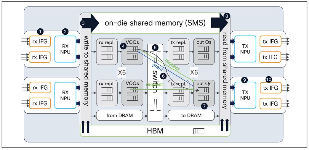
Unicast packet walk inside the Cisco Silicon One ASIC
1. Packet arrives at the ingress port; PHY converts the signal and serializes the bits, and then sends the packet to the Receive Interface Group (Rx IFG).
2. The packet’s Start-of-Packet (SOP) fragment (64B to 384B elements) is processed by the Rx NPU to determine the destination port. The Non-SOP fragments bypass the Receive Network Processor Unit (Rx NPU) and are passed directly to the Shared Memory Packet Buffer (SMS).
3. The packet is stored in the SMS, and a corresponding Packet Descripter (PD) is generated.
4. The PD is stored in the Virtual Output Queue (VOQ) according to destination port.
5. The VOQ requests credits from the destination Output Queue (OQ).
6. Once credit is granted from OQ, the VOQ passes the PD to the slice crossbar.
7. Then, the PD is switched by the crossbar and is stored in the destination OQ.
8. The PD is scheduled from the OQ and presented to the SMS. Then the packet is read out to the Transmit Network Processor Unit (Tx NPU).
9. The packet is processed by the Tx NPU by editing the packet’s SOP elements.
10. The packet is transmitted out of an interface within an Tx IFG.
C9500X series (Silicon One Q200) – multicast forwarding
Figure 30 shows the basic sequence of events when packets enter the Catalyst 9500X Series front panel ports for multicast packet forwarding within the ASIC.
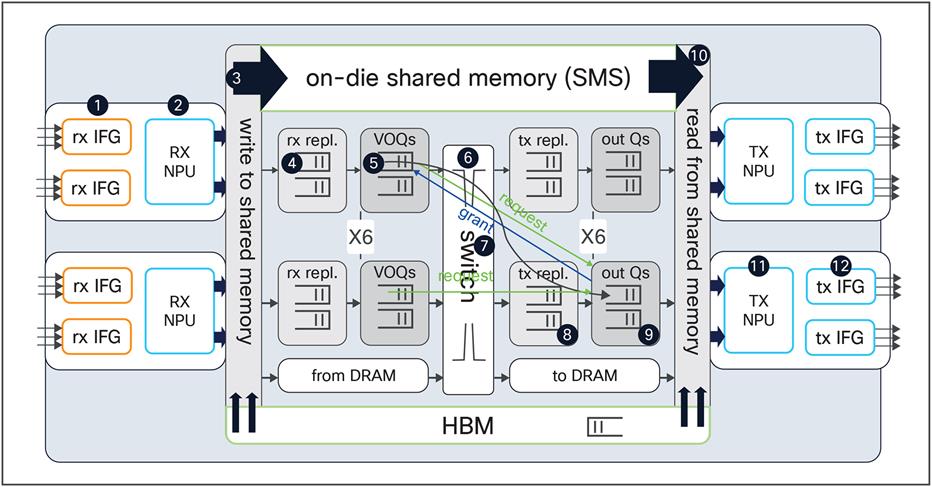
Multicast packet walk inside the Cisco Silicon One ASIC
1. The packet arrives at the ingress port; PHY converts the signal and serializes the bits, and then sends the packet to the Receive Interface Group (Rx IFG).
2. The packet’s Start-of-Packet (SOP) fragment (64B to 384B elements) is processed by the Rx NPU to determine the destination port. The non-SOP fragments bypass the Receive Network Processor Unit (Rx NPU) and are passed directly to the Shared Memory Packet Buffer (SMS).
3. The packet is stored in the SMS , and a corresponding Packet Descripter (PD) is generated.
4. Receive replication (RXPDR) is processed for ingress replication. Each copy made by RXPDR results in an enqueue into the Virtual Output Queue (VOQ).
5. The replicated PDs are stored in the VOQ according to the destination ports.
6. The VOQ requests credits from the destination Output Queue (OQ).
7. Once credit is granted from the OQ, the VOQ passes the PD to the slice crossbar.
8. The PD is then switched by the crossbar and sent to Transmit Replication (TXPDR) for egress multicast replication.
9. Once the packet is replicated, it is stored in the destination OQs.
10. The PD is scheduled from the OQ and presented to the SMS. Then the packet is read out to the Transmit Network Processor Unit (Tx NPU).
11. The packet is processed by the Tx NPU by editing the packet’s SOP elements.
12. The packet is transmitted out of an interface within an Tx IFG.
Cisco Catalyst 9500 Series Switches are the enterprise-class backbone of the Cisco Catalyst 9000 Family of switches, offering a comprehensive high-density portfolio and architectural flexibility with 400 GE, 100 GE, 40 GE, 25 GE, and 10 GE. This new platform is based on the Cisco next-generation programmable Silicon One Q200 ASIC for increased bandwidth, scale, security, and telemetry. The platform also supports infrastructure investment protection with nondisruptive migration from 10 GE to 25 GE and beyond. Cisco Catalyst 9500 Series Switches are built on a modular system architecture designed to provide high performance to meet the evolving needs of highly scalable and growing enterprise networks.
Additional websites that offer more information about the Cisco Catalyst 9500 Series and its capabilities:
● Cisco Catalyst 9500 Series Switches data sheet
● Cisco Catalyst 9500 Series Switches hardware installation guide
● Cisco Catalyst 9000 - Switching for a new era of intent-based networking
● 25GE and 100GE – Enabling higher speeds in the enterprise with investment protection white paper
● Cisco Catalyst 9500 High Performance series performance validation