MPLS for the Catalyst 9000 Switching Family White Paper
Available Languages
Bias-Free Language
The documentation set for this product strives to use bias-free language. For the purposes of this documentation set, bias-free is defined as language that does not imply discrimination based on age, disability, gender, racial identity, ethnic identity, sexual orientation, socioeconomic status, and intersectionality. Exceptions may be present in the documentation due to language that is hardcoded in the user interfaces of the product software, language used based on RFP documentation, or language that is used by a referenced third-party product. Learn more about how Cisco is using Inclusive Language.
Numerous businesses have recognized Multiprotocol Label Switching (MPLS) as an excellent solution to replace costly long-haul Wide-Area Network (WAN) circuits that connect their core infrastructure. MPLS is a well-established technology, initially popularized as a cost-effective alternative to packetized services like Asynchronous Transfer Mode and Frame Relay in branch offices. As the protocol continued to evolve, it not only brought cost savings but also introduced additional advantages. These include the ability to prioritize voice traffic through Quality of Service (QoS) to enhance voice over IP quality, simplify network complexity, and fortify disaster recovery and business continuity strategies. MPLS is particularly appealing to distributed enterprises seeking both Layer 2 and Layer 3 services, as well as crucial capabilities like 6PE and 6VPE.This white paper explores these challenges and how MPLS addresses them.
This white paper discusses the benefits and use cases of MPLS technology in enterprise networks. It focuses primarily on the Cisco Catalyst™ 9000 switching family and how the platform can be leveraged for segmentation using MPLS in campus networks. It is mainly intended to discuss MPLS technology details, scale, and limitations and how it can be leveraged in a campus environment. In addition to the technical details, this document presents design considerations and sample configurations to illustrate the MPLS designs.
This document assumes that the reader is familiar with the operation and configuration of MPLS and Border Gateway Protocol (BGP). It focuses entirely on design, deployment, and configuration considerations for the MPLS architecture and the related handoff to external.
Segmentation designs in campus/enterprise networks
Currently, there are many segmentation technologies that can be leveraged to achieve segmentation in a campus network. Below are some of the available technologies.
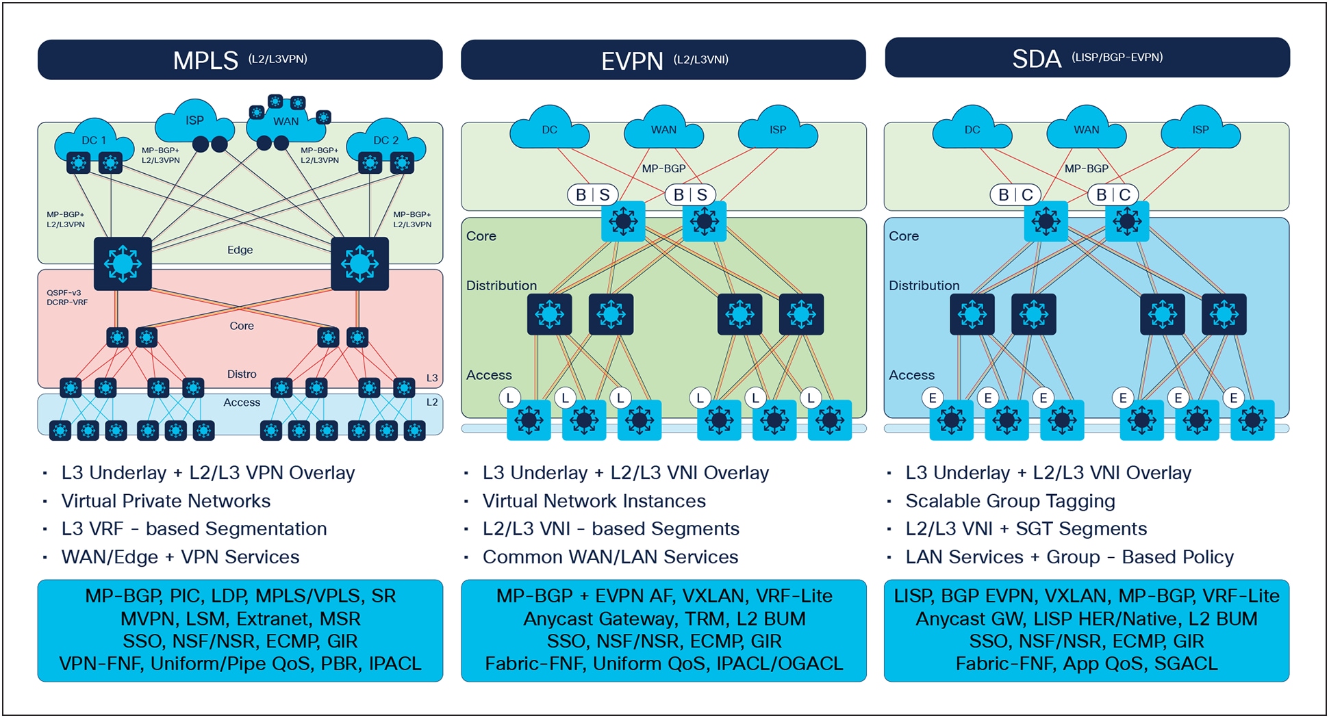
Segmentation technologies
This technology leverages MPLS and BGP to achieve segmentation in the network. Forwarding is done using labels in the core network. This is an overlay technology that can be deployed on an existing underlay.
The Cisco® Software-Defined Access (SD-Access) Fabric solution provides segmentation along with the added benefits of Automation and Assurance. Cisco SD-Access leverages either LISP or BGP at the control plane and Virtual Extensible LAN (VXLAN) at the data plane to achieve segmentation. VXLAN is a next-generation segmentation technology which encapsulates Layer 2 over Layer 3 to achieve segmentation and extend a Layer 2 domain over a Layer 3 network.SD-Access also can provide micro-segmentation, leveraging the Cisco Identity Services Engine (ISE) that is integrated as part of SD-Access. SD-Access LISP leverage LISP at the control plane and VXLAN for the data plane whereas BGP EVPN leverages BGP for the control plane and VXLAN for the data plane. More details regarding this solution can be found at the following website.
Cisco SD-Access
This section presents a brief overview of the MPLS architecture and the need for MPLS in enterprise networks.
MPLS operates at the data-link layer (Layer 2) and network layer (Layer 3) of the Open Systems Interconnect (OSI) model. At its core, MPLS uses labels (essentially a Layer 2-compatible identifier derived from a binding between an IP prefix and a label) to simplify and expedite the routing process. When a packet enters an MPLS network, a label is added to its header. This label carries information that determines the packet's forwarding path through the network. The label is used by routers to make forwarding decisions, eliminating the need for complex and time-consuming IP address lookups.
The MPLS header is 32 bits and is inserted between the Layer 2 and Layer 3 header. The label is 20 bits.
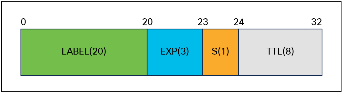
MPLS header
The header components are as follows:
Label: The 20-bit label value, used for identifying the forwarding equivalence class (FEC).
EXP: The 3-bit traffic class, used to copy the QoS from IP to label or from label to IP.
S: A 1-bit bottom-of-stack flag. A label stack can contain multiple labels. The label nearest to the Layer 2 header is called the top label, and the label nearest to the Layer 3 header is called the bottom label. The S field is set to 1 if the label is the bottom label, and is set to 0 if not.
TTL: An 8-bit time-to-live field used for MPLS loop prevention.
MPLS allows routers within the network to establish label-switched paths (LSPs) based on the labels. These paths create virtual circuits or tunnels through the network, guiding packets efficiently from source to destination. The labels are distributed and maintained through a protocol such as the Label Distribution Protocol (LDP).
With the MPLS architecture, macro-level segmentation can be achieved. MPLS transport allows enterprises the benefits of label switching, with a way to multiplex multiple services on a single MPLS IP transport path. Multiple services can be segmented on the box using virtual routing and forwarding (VRF) instances. Services in VRF-1 will be completely isolated from services in VRF-2, providing utmost security.
● Security
MPLS-based VPNs provide secure and efficient connectivity between different locations or sites. MPLS allows for the creation of private and isolated communication paths within the network, ensuring that traffic remains separate and confidential for different VPN customers or departments. This can be particularly useful for organizations with multiple locations that need to share data and applications securely.
● Merger/acquisition
Mergers and acquisitions are one of the most challenging types of integrations. MPLS eases the deployments, whether enterprises are merging, separating, being acquired, or simply expanding to different locations — it’s the application and business requirements that are the most critical components driving design and implementation strategies.
MPLS relies on label lookup for packet forwarding in the core, thereby reducing the number of IP lookups needed in the core. This helps networks scale more easily by reducing the size and complexity of routing tables. As a result, the network is more efficient and simpler to manage.
● Simplified routing
MPLS simplifies the routing process by replacing traditional routing tables with labels, resulting in faster forwarding and reduced routing overhead. With MPLS, the network can handle increasing traffic volumes and accommodate network growth without compromising performance. The use of labels instead of complex routing tables simplifies configuration and reduces the complexity of the network.
MPLS allows for efficient traffic engineering within the campus network. It provides the ability to create explicit paths for specific types of traffic, enabling better control and optimization of network resources. This helps to ensure optimal performance, minimize congestion, and meet QoS requirements.
In traditional networks, traffic is forwarded using a forwarding table based on IP lookup, such as IP destination to next-hop lookup. In MPLS networks, forwarding is done based on the label lookup. MPLS leverages the current underlay (the underlying infrastructure that provides basic connectivity and routing services) to build LDP neighbors and exchange labels.
Devices that are participating in MPLS forwarding will perform one of the following operations, based on the role that the device is playing.
● Push: Assigns one or more labels to route traffic to the next-hop device within the LSP (Label Edge Router [LER]).
● Swap: Replaces labels, one hop at a time, with its respective local label (Label Switching Router [LSR]).
● Pop: Removes one or more labels by last or next-to-last (penultimate router) in the LSP.
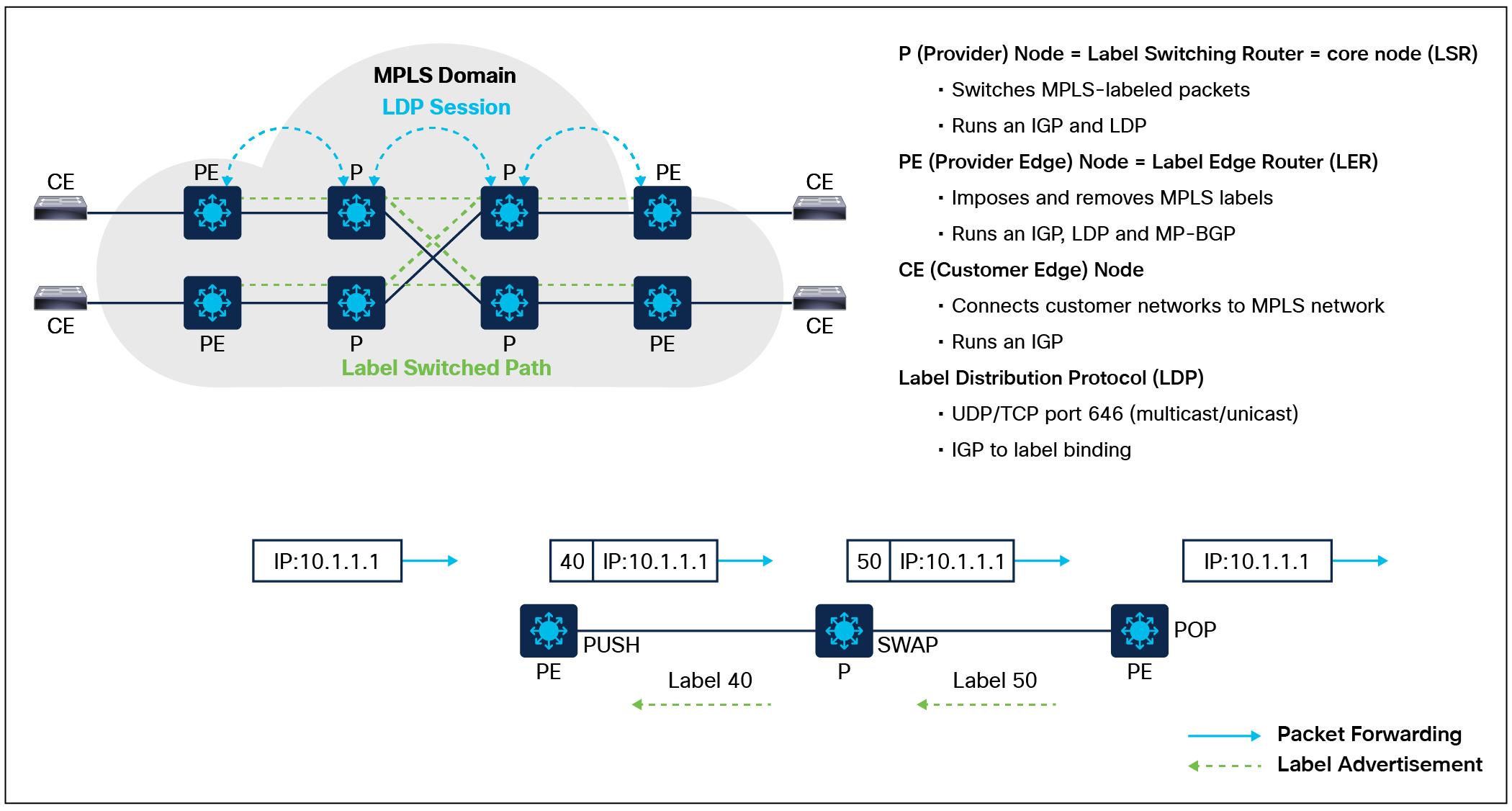
Illustrates the operation of devices within the MPLS network.
1. Label distribution: The first step in the MPLS process is the distribution of labels throughout the network. This can be achieved using protocols such as LDP or the Resource Reservation Protocol (RSVP).
2. Label switching: When a packet enters the MPLS network, a label is added to the packet header. Routers within the network use this label to make forwarding decisions based on the LSP established for that packet.
3. Label swapping: As the packet traverses the MPLS network, the label is swapped at each hop. The router looks up the label in its forwarding table to determine the next hop and then swaps the label with the label of the next hop.
4. Label removal: When the packet reaches its destination, the label is removed and the packet is forwarded based on its original IP destination address.
In an enterprise campus network, MPLS VPNs can be used to connect multiple sites or departments together securely and efficiently over a service provider's network.
By deploying MPLS VPNs in an enterprise campus network, network administrators can create private and isolated communication paths between different parts of the campus, ensuring that traffic remains confidential and separate. VRFs are used to create isolated routing information bases (RIBs) for different network entities or customers. Each VRF functions as a separate routing table, ensuring network isolation. This is particularly important in scenarios where multiple customers or network segments need to coexist on the same physical infrastructure while maintaining logical separation.
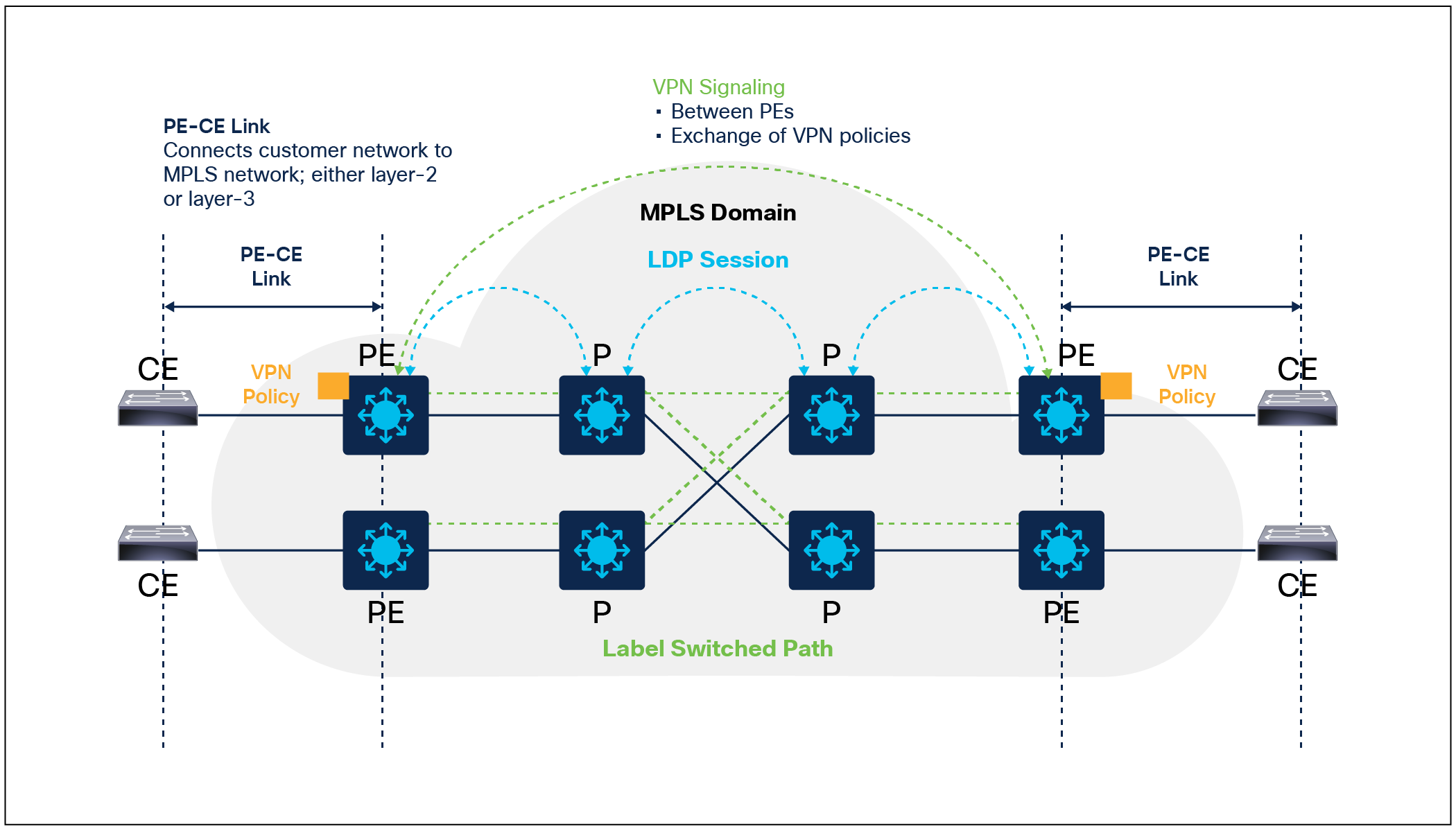
MPLS VPN Deployment Overview
MPLS supports two types of VPN services: Layer 2 VPN (L2VPN) and Layer 3 VPN (L3VPN).
L2VPN provides point-to-point (ELINE) and/or point-to-multipoint (ELAN) connectivity between two sites or customer premises over an MPLS network. It is used to transport Layer 2 traffic between different sites. L2VPN allows customers to extend their Layer 2 network across multiple sites while maintaining a consistent MAC address table and network topology.
L2VPN can be further categorized into two types:
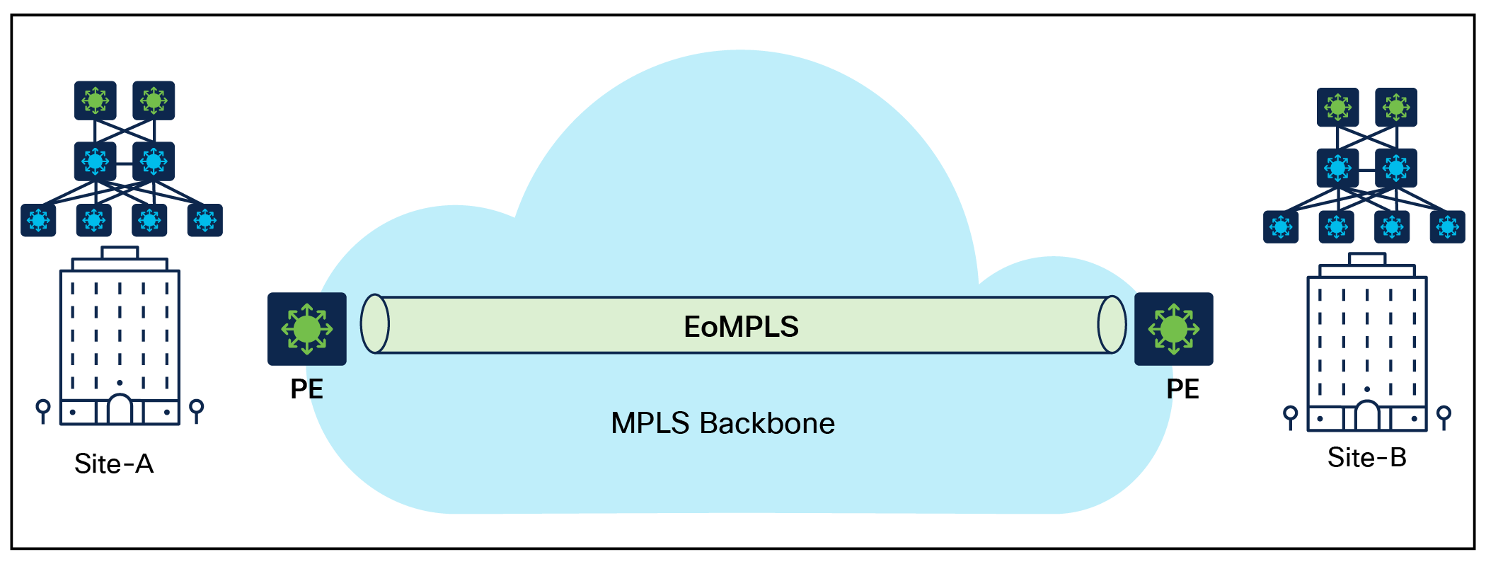
● Ethernet over MPLS (EoMPLS): EoMPLS provides a scalable point-to-point solution for connecting multiple customer sites to the same Layer 2 network. It enables customers to use standard Ethernet switches, and it supports multipathing, load balancing, and fast convergence.
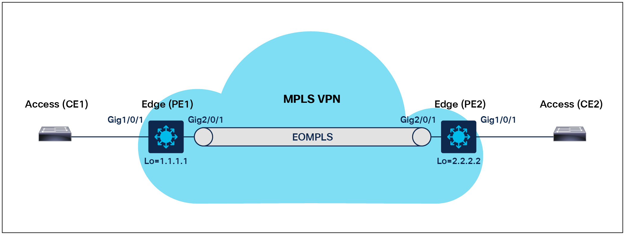
EoMPLS Deployment Overview
| PE1 |
PE2 |
| interface loopback 0 ip address 1.1.1.1 255.255.255.255 ! no switchport no ip address no keepalive ! ! Define EoMPLS PWI interface pseudowire101 encapsulation mpls neighbor 2.2.2.2 101 load-balance flow ip dst-ip load-balance flow-label both ! Attach L2VPN to PW l2vpn xconnect context pw101 member pseudowire101 member GigabitEthernet1/0/1 |
interface loopback 0 ip address 2.2.2.2 255.255.255.255 ! interface GigabitEthernet2/0/1 no switchport no ip address no keepalive ! ! Define EoMPLS PWI interface pseudowire101 encapsulation mpls Neighbor 1.1.1.1 101 load-balance flow ip dst-ip load-balance flow-label both ! Attach L2VPN to PW l2vpn xconnect context pw101 member pseudowire101 member GigabitEthernet1/0/1 |
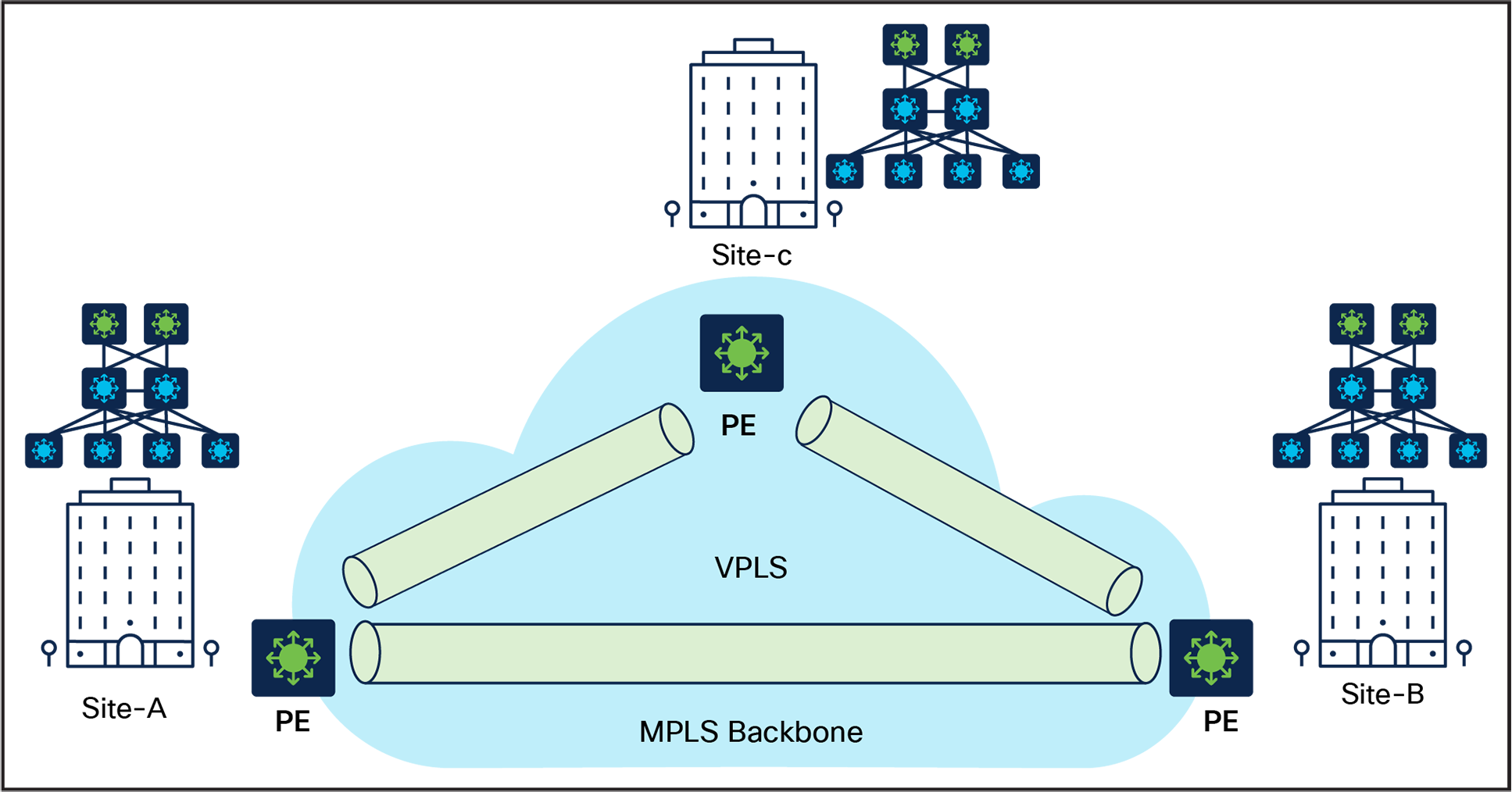
● Virtual Private LAN Service (VPLS): VPLS enables multiple customer sites to be connected to the same point-to-multipoint Layer 2 network, as if they were connected to the same LAN segment. VPLS creates a single, unified broadcast domain across all connected sites.
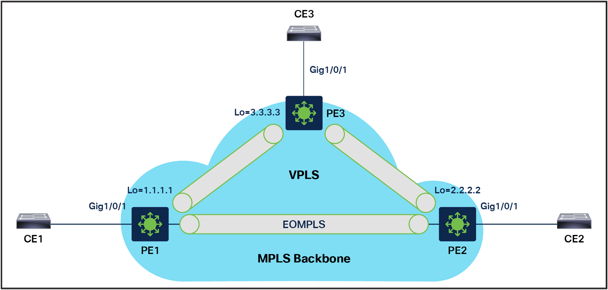
VPLS Deployment Overview
| PE1 |
PE3 |
PE2 |
| interface loopback 0 ip address 1.1.1.1 255.255.255.255
vlan 100 ! Define VPLS VFI l2 vfi PE1-VPLS-A manual vpn id 100 neighbor 2.2.2.2 2 encapsulation mpls neighbor 3.3.3.3 3 encapsulation mpls ! ! Attach VFI to VLAN interface interface vlan 100 xconnect vfi PE1-VPLS-A ! ! Attachment Circuit config interface GigabitEthernet1/0/1 switchport switchport trunk encapsulation dot1q switchport mode trunk |
interface loopback 0 ip address 3.3.3.3 255.255.255.255
vlan 100 ! Define VPLS VFI l2 vfi PE3-VPLS-A manual vpn id 100 neighbor 1.1.1.1 3 encapsulation mpls neighbor 2.2.2.2 3 encapsulation mpls ! ! Attach VFI to VLAN interface interface vlan 100 xconnect vfi PE3-VPLS-A ! ! Attachment Circuit config interface GigabitEthernet1/0/1 switchport switchport trunk encapsulation dot1q switchport mode trunk |
interface loopback 0 ip address 2.2.2.2 255.255.255.255
vlan 100 ! Define VPLS VFI l2 vfi PE2-VPLS-A manual vpn id 100 neighbor 1.1.1.1 2 encapsulation mpls neighbor 3.3.3.3 23 encapsulation mpls ! ! Attach VFI to VLAN interface interface vlan 100 xconnect vfi PE2-VPLS-A ! ! Attachment Circuit config interface GigabitEthernet1/0/1 switchport switchport trunk encapsulation dot1q switchport mode trunk |
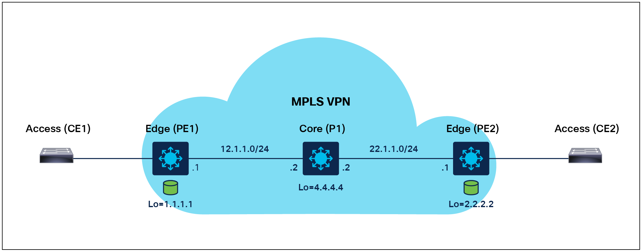
L3VPN provides point-to-point connectivity between two sites or customer premises over an MPLS network. It is used to transport Layer 3 traffic, such as IP packets, between different sites. L3VPN allows customers to extend their Layer 3 network across multiple sites while maintaining a consistent IP addressing scheme and network topology.

Layer 3 VPN Deployment Overview
1. Configure LDP between PE1, P1, and PE2.
| PE1 |
P1 |
PE2 |
| mpls label protocol ldp Mpls ip ! interface GigabitEthernet1/0/4 ip address 12.1.1.1 255.255.255.0 mpls ip mpls label protocol ldp ! mpls ldp router-id Loopback0 |
mpls label protocol ldp mpls ip ! interface GigabitEthernet1/0/4 no switchport ip address 12.1.1.2 255.255.255.0 mpls ip mpls label protocol ldp ! interface GigabitEthernet1/0/6 no switchport ip address 22.1.1.2 255.255.255.0 mpls ip mpls label protocol ldp ! mpls ldp router-id Loopback0 |
mpls label protocol ldp mpls ip ! interface TenGigabitEthernet1/0/6 no switchport ip address 22.1.1.1 255.255.255.0 mpls ip mpls label protocol ldp ! mpls ldp router-id Loopback0 |
2. Configure the VRF interface on PE1 and PE2.
| PE1 |
PE2 |
| vrf definition green rd 100:1 ! address-family ipv4 route-target export 100:1 route-target import 100:1 exit-address-family ! interface GigabitEthernet1/0/11 no switchport vrf forwarding green ip address 10.1.1.1 255.255.255.0 |
vrf definition green rd 100:1 ! address-family ipv4 route-target export 100:1 route-target import 100:1 exit-address-family ! interface GigabitEthernet1/0/11 no switchport vrf forwarding green ip address 20.1.1.1 255.255.255.0 |
3. Configure MP-iBGP between PE1 and PE2.
| PE1 |
PE2 |
| router bgp 100 bgp log-neighbor-changes neighbor 2.2.2.2 remote-as 100 neighbor 2.2.2.2 update-source Loopback0 ! address-family vpnv4 neighbor 2.2.2.2 activate neighbor 2.2.2.2 send-community extended neighbor 2.2.2.2 next-hop-self exit-address-family ! address-family ipv4 vrf green redistribute connected redistribute static exit-address-family |
router bgp 100 bgp log-neighbor-changes neighbor 1.1.1.1 remote-as 100 neighbor 1.1.1.1 update-source Loopback0 ! address-family vpnv4 neighbor 1.1.1.1 activate neighbor 1.1.1.1 send-community extended neighbor 1.1.1.1 next-hop-self exit-address-family ! address-family ipv4 vrf green redistribute connected redistribute static exit-address-family |
Layer 3 VPN control and data plane processing
VPN control plane processing (exchange of VPN policies among PE routers)
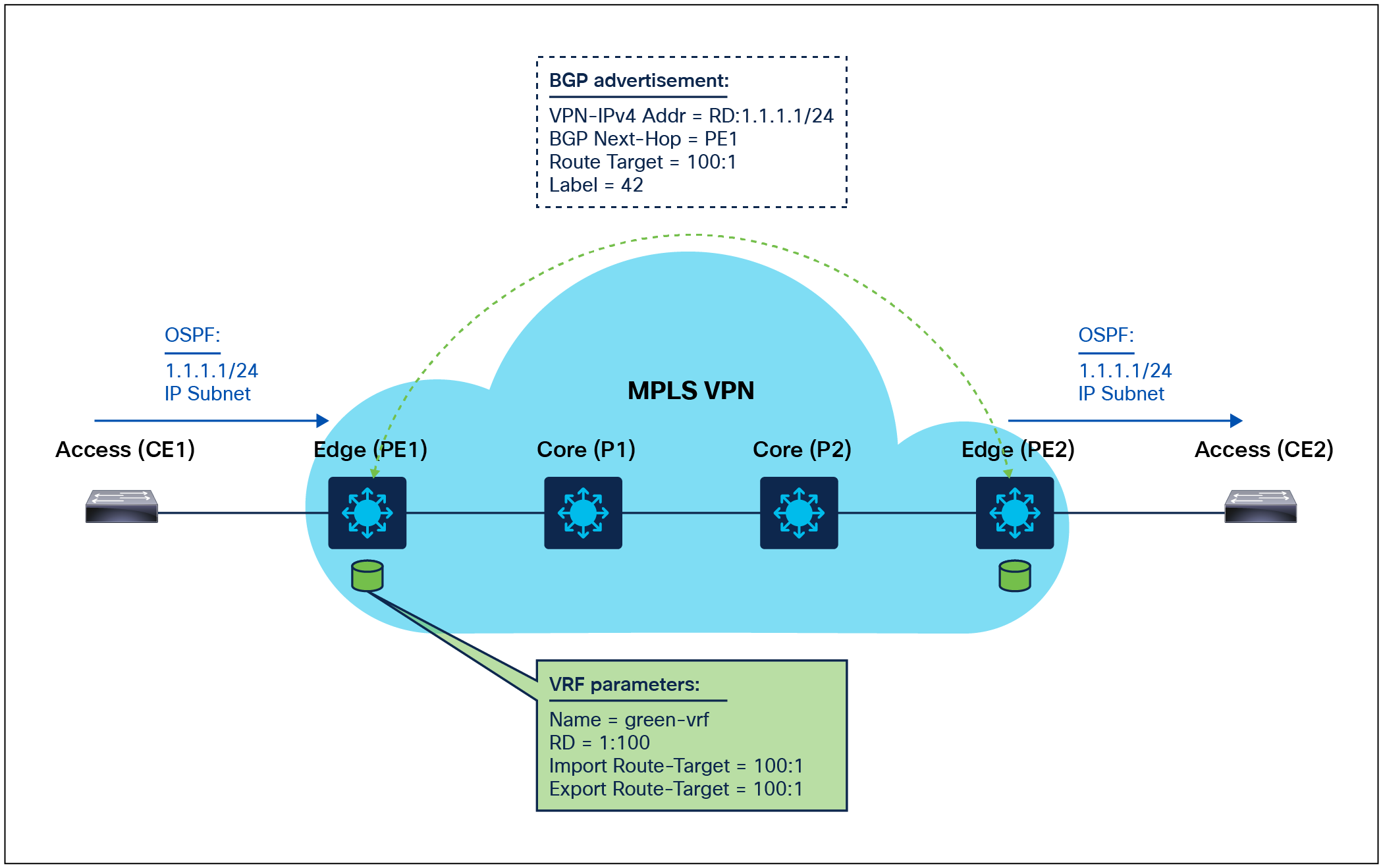
Layer 3 VPN control plane processing
1. CE1 redistributes IPv4 route to PE1 via Open Shortest Path First (OSPF).
2. PE1 allocates a VPN label for the prefix learned from CE1 to create a unique VPNv4 route.
3. PE1 redistributes the VPNv4 route into MP-iBGP, sets itself as a next hop, and relays VPN site routes to PE2.
4. PE2 receives the VPNv4 route and, via processing in local VRF (green), redistributes the original IPv4 route to CE2.
VPN data plane processing (forwarding of Layer 3 MPLS VPN packets)
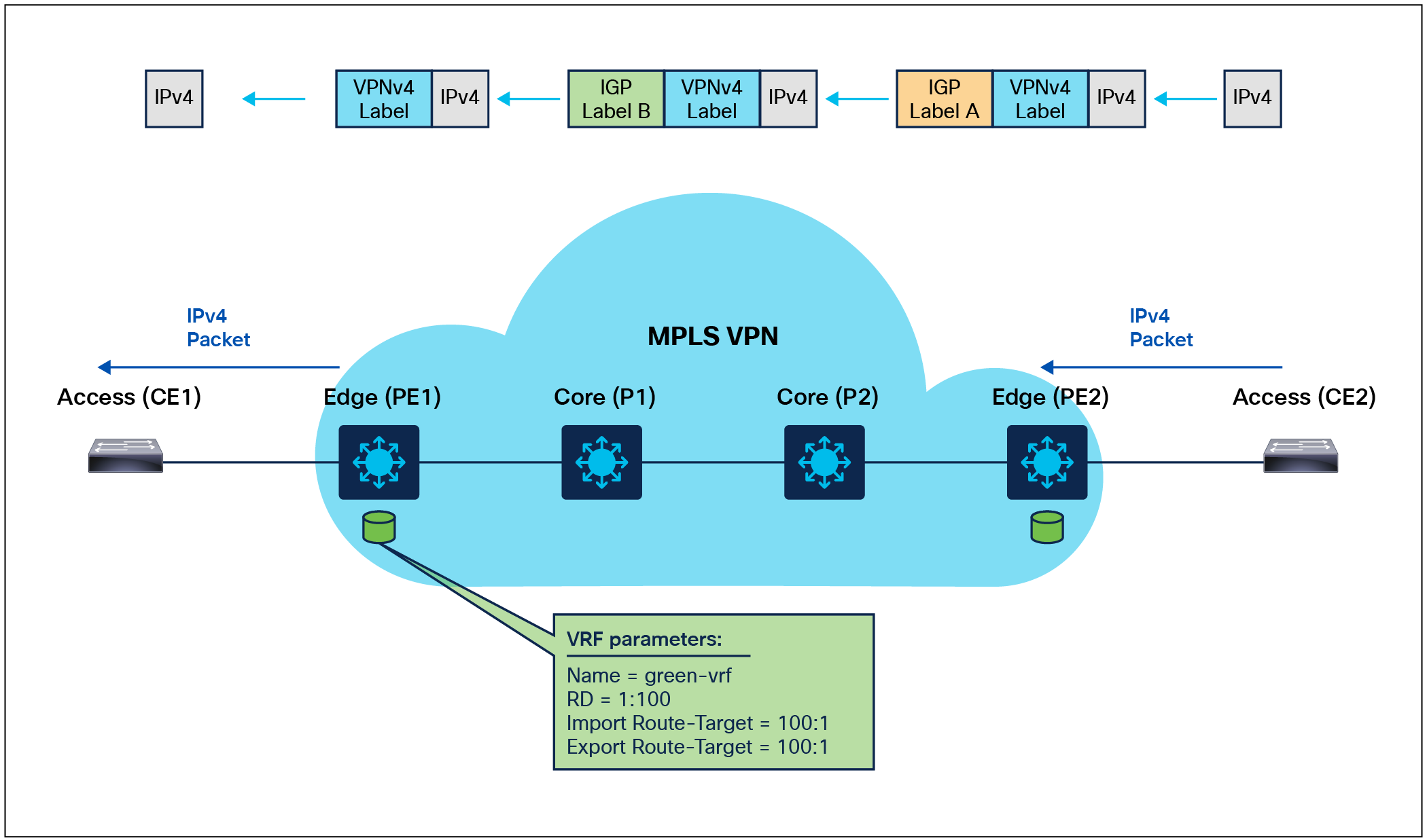
Layer 3 VPN data plane processing
1. CE2 forwards an IPv4 packet to PE2.
2. PE2 imposes a preallocated VPN label to the IPv4 packet received from CE2 (learned via MP-iBGP).
3. PE2 also imposes an outer Interior Gateway Protocol (IGP) label ‘A’ (learned via LDP) and forwards the labeled packet to P2.
4. P2 router swaps the outer IGP label and forwards the label packet to P1. A -> B.
5. P1 router strips the outer IGP label ‘B’ (PHP) and forwards the packet to PE1.
6. Router PE1 strips the VPN label and forwards the IPv4 packet to CE1.
The implementation of network segmentation in an enterprise environment caters to the distinct connectivity needs of various user groups and organizations. This approach offers several advantages. First, network segmentation can be accomplished with configuration efforts focused solely on the network's edge nodes. Second, it provides flexibility in routing, enabling the easy configuration of diverse IP connectivity scenarios, including options like full or partial mesh networks. This versatility in routing empowers organizations to design their network infrastructure based on specific requirements efficiently.
The mVPN feature provides the ability to support multicast over a Layer 3 VPN. It enables the distribution of multicast traffic over a VPN infrastructure, allowing multiple sites to participate in the same multicast group while isolating the multicast traffic within the mVPN. It can be used to support various multicast applications like video streaming, voice, and data to an MPLS VPN network core. The Catalyst 9000 switches support different mVPN models and methods, including the following.
Rosen/Generic Routing Encapsulation (GRE)
The Rosen/GRE approach, one of the early methods for implementing mVPN, uses GRE tunnels to convey multicast traffic within an MPLS network.
GRE tunnels: In this model, dedicated GRE tunnels are established for each VPN group or multicast distribution, facilitating the transmission of multicast data between provider edge (PE) routers within the mVPN.
Simplicity: The Rosen/GRE model offers relative simplicity, making it well-suited for mVPN deployments at a smaller scale. Nevertheless, it may introduce additional overhead due to the deployment of individual tunnels for each group.
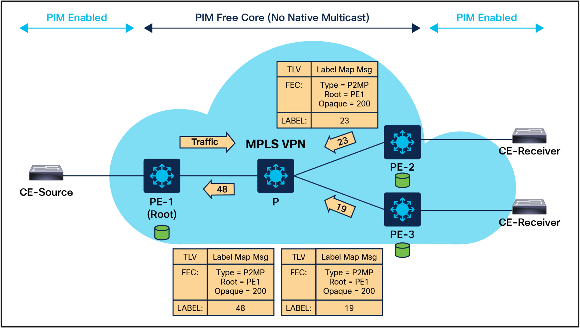
Label-Switched Multicast/Multicast Label Distribution Protocol (LSM/MLDP)
LSM/MLDP, a more advanced mVPN approach, combines MPLS with MLDP to efficiently configure multicast distribution trees. The MLDP-based mVPN feature provides extensions to LDP for the setup of point-to-multipoint (P2MP) and multipoint-to-multipoint (MP2MP) LSPs for transport in the mVPN core network.
MPLS labels: Within this model, MPLS labels are assigned to multicast flows, optimizing the forwarding of multicast traffic across the MPLS network. MLDP is employed to establish the multicast distribution trees.
Efficiency: LSM/MLDP enhances efficiency in comparison to Rosen/GRE by eliminating the necessity for individual GRE tunnels for each multicast group. This approach allows for more scalable and optimized multicast traffic routing.
A multicast distribution tree (MDT) is a fundamental component used to optimize the forwarding of multicast traffic within a VPN. mVPN is designed to support efficient and scalable multicast communication between sites within a VPN, and MDTs play a crucial role in achieving this goal. The Catalyst 9000 switches support default and data MDTs to ensure that multicast traffic is efficiently and reliably delivered within the MPLS VPN domain.
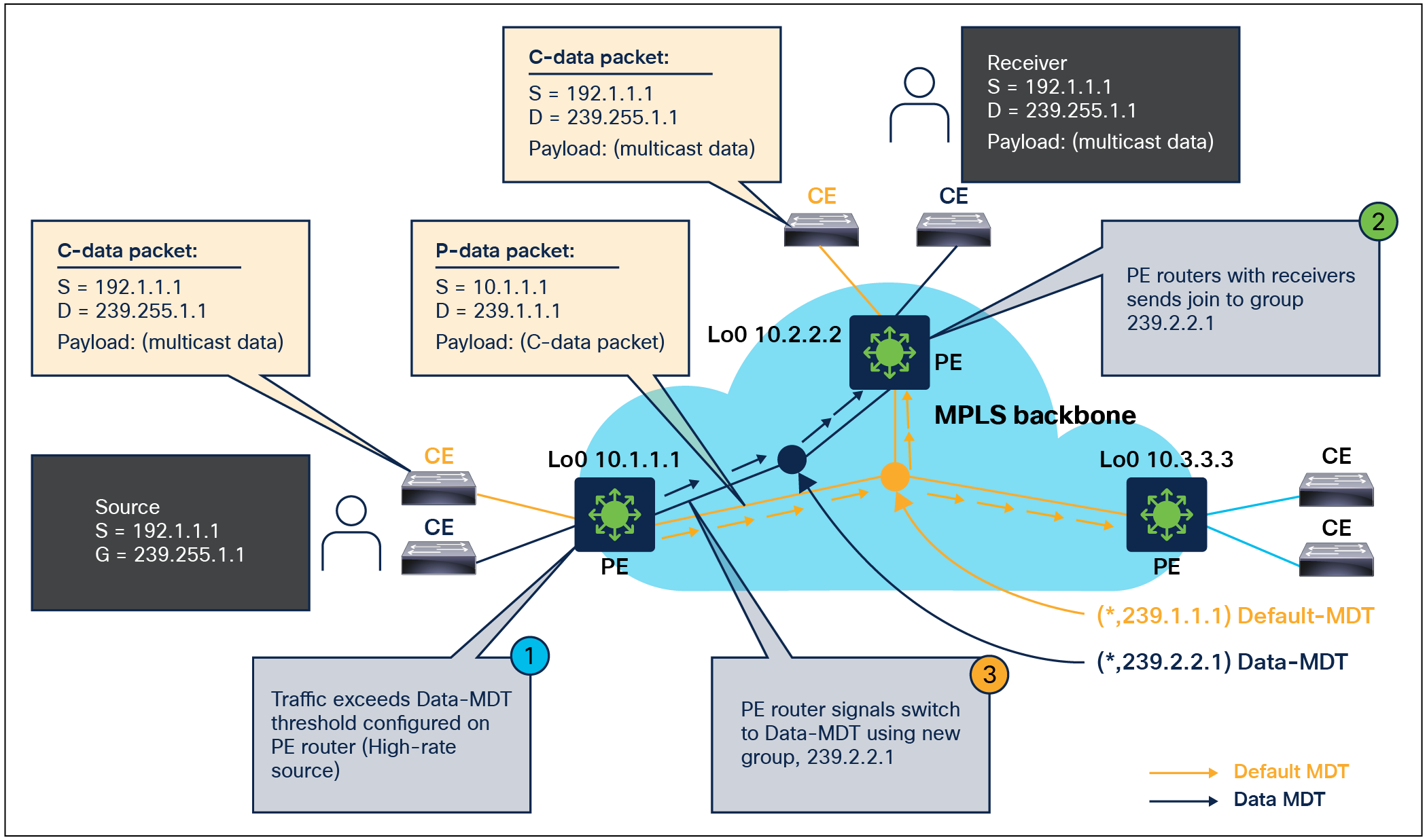
Multicast vpn default and data MDT Overview
The default MDT is used for control traffic between the customer edge (CE) nodes and the PE nodes in the mVPN network. It is used to exchange routing information, multicast membership information, and other control messages necessary to establish and maintain the mVPN service.
The data MDT is used for data traffic between the CE nodes. It is created and maintained dynamically based on the multicast traffic requirements of the customers. The data MDT provides a dedicated MDT for each multicast group to ensure efficient and scalable delivery of multicast traffic across the mVPN network.
Rosen/GRE mVPN configuration
Rosen/GRE mvpn Deployment Overview
| PE1 |
P1 |
PE2 |
| Ip multicast-routing ! interface GigabitEthernet1/0/4 ip address 12.1.1.1 255.255.255.0 mpls ip mpls label protocol ldp Ip pim sparse-mode ! ip multicast-routing vrf green ! Router bgp 100 address-family mdt Neighbor 2.2.2.2 activate Neighbor 2.2.2.2 send-community extended Exit-address-family ! Ip pim ssm default Ip pim vrf green rp-address 12.1.1.1 ! |
Ip multicast-routing ! mpls label range 16 10000 static 10001 15000 mpls label protocol ldp mpls ip ! interface GigabitEthernet1/0/4 no switchport ip address 12.1.1.2 255.255.255.0 mpls ip mpls label protocol ldp Ip pim sparse-mode ! interface GigabitEthernet1/0/6 no switchport ip address 22.1.1.2 255.255.255.0 mpls ip mpls label protocol ldp Ip pim sparse-mode ! Ip pim ssm default ! mpls ldp router-id Loopback0 |
Ip mullticast-routing ! interface TenGigabitEthernet1/0/6 no switchport ip address 22.1.1.1 255.255.255.0 mpls ip mpls label protocol ldp Ip pim sparse-mode ! ip multicast-routing vrf green ! Router bgp 100 address-family mdt Neighbor 1.1.1.1 activate Neighbor 1.1.1.1 send-community extended Exit-address-family ! Ip pim ssm default Ip pim vrf green rp-address 12.1.1.1 ! |
LSM/MLDP mVPN configuration
LSM/MLDP mVPN Deployment Overview
| PE (default MDT) |
PE (data MDT) |
|
ip pim mpls source Loopback0 ip multicast-routing ip multicast-routing vrf VRF ! vrf definition VRF rd 1:1 vpn id 1:10 route-target export 1:1 route-target import 1:1 ! address-family ipv4 mdt preference mldp mdt default mpls mldp 172.168.1.81 exit-address-family ! |
ip pim mpls source Loopback0 ip multicast-routing ip multicast-routing vrf VRF ! vrf definition VRF rd 1:1 vpn id 1:10 route-target export 1:1 route-target import 1:1 ! address-family ipv4 mdt default mpls mldp 172.168.1.81 mdt data mpls mldp 100 mdt data threshold 1 exit-address-family ! |
Supported MLDP profiles and configuration
| Profile name |
Supported on MLDP |
| Profile 1 Default MDT - MLDP MP2MP - PIM C-mcast Signaling |
Yes |
| Profile 13 Default MDT - MLDP - MP2MP - BGP-AD - BGP C-mcast Signaling |
Yes |
| Profile 14 Partitioned MDT - MLDP P2MP - BGP-AD - BGP C-mast Signaling |
Yes |
| PE (MVPN profile 1) |
PE (MVPN profile 13) |
PE (MVPN profile 14) |
| ip pim mpls source Loopback0 ip multicast-routing ip multicast-routing vrf VRF1 ! vrf definition VRF1 rd 1:1 vpn id 1:10 ! address-family ipv4 route-target export 1:1 route-target import 1:1 mdt default mpls mldp 172.168.1.81 exit-address-family
router bgp 1 bgp log-neighbor-changes neighbor 10.100.1.7 remote-as 1 neighbor 10.100.1.7 update-source Loopback0 ! address-family vpnv4 neighbor 10.100.1.7 activate neighbor 10.100.1.7 send-community extended exit-address-family ! address-family ipv4 vrf VRF1 redistribute connected neighbor 10.2.2.9 remote-as 65002 neighbor 10.2.2.9 activate exit-address-family |
ip pim mpls source Loopback0 ip multicast-routing ip multicast-routing vrf VRF1 ! vrf definition VRF1 rd 1:1 vpn id 1:10 ! address-family ipv4 route-target export 1:1 route-target import 1:1 mdt auto-discovery mldp mdt default mpls mldp 172.168.1.81 mdt overlay bgp exit-address-family ! router bgp 1 bgp log-neighbor-changes neighbor 10.100.1.7 remote-as 1 neighbor 10.100.1.7 update-source Loopback0 ! address-family vpnv4 neighbor 10.100.1.7 activate neighbor 10.100.1.7 send-community extended exit-address-family ! address-family ipv4 mvpn neighbor 10.100.1.7 activate neighbor 10.100.1.7 send-community extended exit-address-family |
ip pim mpls source Loopback0 ip multicast-routing ip multicast-routing vrf VRF1 ! vrf definition VRF1 rd 1:1 ! address-family ipv4 route-target export 1:1 route-target import 1:1 mdt auto-discovery mldp mdt strict-rpf interface mdt partitioned mldp p2mp mdt overlay use-bgp exit-address-family ! router bgp 1 bgp log-neighbor-changes neighbor 10.100.1.7 remote-as 1 neighbor 10.100.1.7 update-source Loopback0 ! address-family vpnv4 neighbor 10.100.1.7 activate neighbor 10.100.1.7 send-community extended exit-address-family ! address-family ipv4 mvpn neighbor 10.100.1.7 activate neighbor 10.100.1.7 send-community extended exit-address-family |
MPLS Traffic Engineering (MPLS TE)
MPLS TE helps to accomplish several goals, such as optimal bandwidth utilization, capacity planning, and congestion avoidance/handling in an MPLS domain. It involves the control and management of traffic flows within an MPLS network by manipulating the LSPs that carry the data. MPLS TE works by learning about the topology and resources available in a network. It then maps the traffic flows to a particular path based on the resources that the traffic flow requires and the resources that are available. MPLS TE builds unidirectional tunnels from a source to the destination in the form of LSPs, which are then used for forwarding traffic.
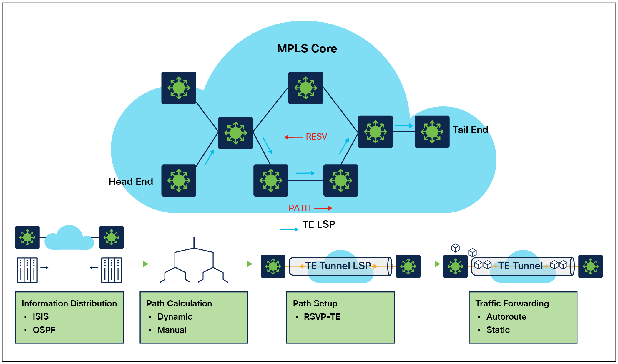
MPLS Traffic engineering
MPLS TE automatically establishes and maintains LSPs across the backbone by using Resource Reservation Protocol (RSVP). The path that an LSP uses is determined by the LSP resource requirements and network resources, such as bandwidth. Available resources are flooded by means of extensions to a link state-based IGP. Traffic engineering tunnels are calculated at the LSP head, based on a fit between the required and available resources (constraint-based routing). The IGP automatically routes the traffic to these LSPs. Typically, a packet traveling across the MPLS TE backbone travels on a single LSP that connects the ingress point to the egress point. The Catalyst 9000 switches bring MPLS TE capabilities to the portfolio starting with
Cisco IOS® XE 17.6.1.
MPLS TE PE-to-PE tunnel configuration
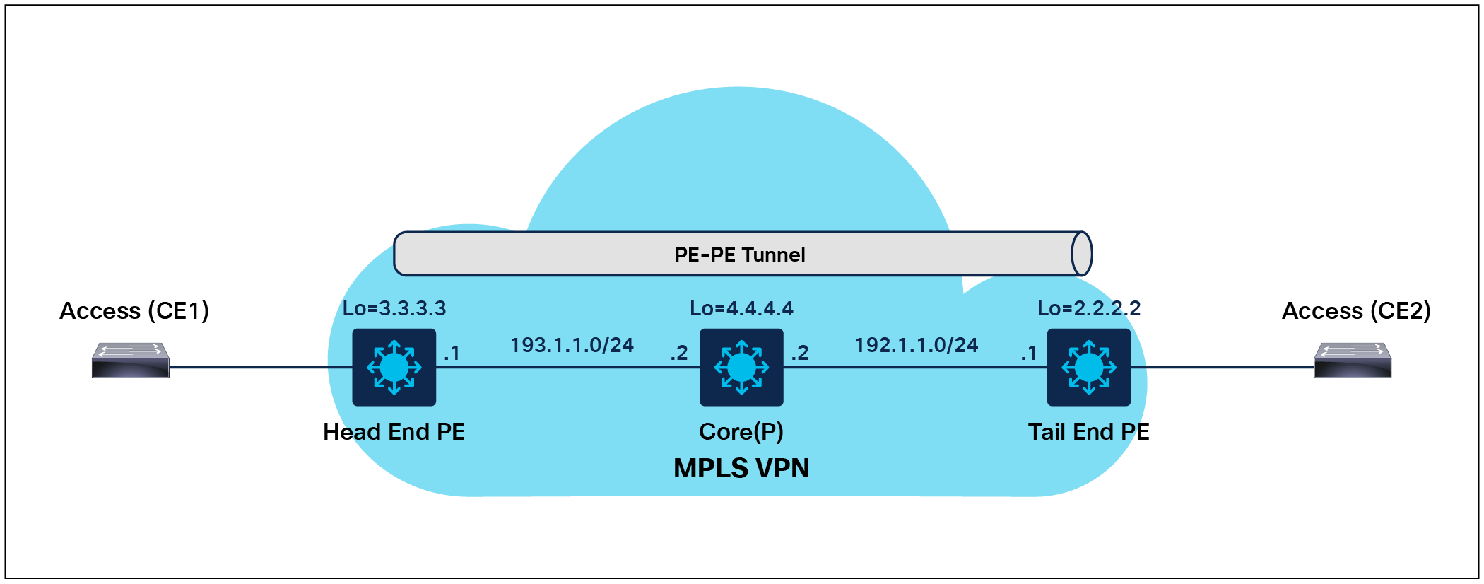
MPLS TE PE-to-PE tunnel Deployment Overview
1. Interface parameter and backbone IGP MPLS TE configuration
| Head end PE |
Core (P) |
Tail end PE |
| interface Port-channel30 no switchport ip address 193.1.1.1 255.255.255.0 ip ospf 1 area 0 mpls ip mpls traffic-eng tunnels ip rsvp bandwidth
interface Loopback0 ip address 3.3.3.3 255.255.255.255 ip ospf 1 area 0
router ospf 1 router-id 3.3.3.3 nsr nsf mpls traffic-eng router-id Loopback0 mpls traffic-eng area 0 |
interface Port-channel30 no switchport ip address 193.1.1.2 255.255.255.0 ip ospf 1 area 0 mpls ip mpls traffic-eng tunnels ip rsvp bandwidth
interface Port-channel50 no switchport ip address 192.1.1.2 255.255.255.0 ip ospf 1 area 0 mpls ip mpls traffic-eng tunnels ip rsvp bandwidth
interface Loopback0 ip address 4.4.4.4 255.255.255.255 ip ospf 1 area 0 router ospf 1 router-id 4.4.4.4 nsr nsf mpls traffic-eng router-id Loopback0 mpls traffic-eng area 0 |
interface Port-channel50 no switchport ip address 192.1.1.1 255.255.255.0 ip ospf 1 area 0 mpls ip mpls traffic-eng tunnels ip rsvp bandwidth
interface Loopback0 ip address 2.2.2.2 255.255.255.255 ip ospf 1 area 0
router ospf 1 router-id 2.2.2.2 nsr nsf mpls traffic-eng router-id Loopback0 mpls traffic-eng area 0 |
2. TE tunnel configuration
| Head end PE |
Core (P) |
Tail end PE |
| mpls traffic-eng tunnels mpls ldp graceful-restart mpls ldp discovery targeted-hello accept mpls ldp router-id Loopback0 force ip rsvp signalling hello graceful-restart mode help-neighbor mpls traffic-eng nsr
interface Tunnel100 ip unnumbered Loopback0 tunnel mode mpls traffic-eng tunnel destination 2.2.2.2 tunnel mpls traffic-eng autoroute announce tunnel mpls traffic-eng priority 7 7 tunnel mpls traffic-eng bandwidth 500 tunnel mpls traffic-eng path-option 1 dynamic |
mpls traffic-eng tunnels mpls ldp graceful-restart mpls ldp discovery targeted-hello accept mpls ldp router-id Loopback0 force ip rsvp signalling hello graceful-restart mode help-neighbor mpls traffic-eng nsr |
mpls traffic-eng tunnels mpls ldp graceful-restart mpls ldp discovery targeted-hello accept mpls ldp router-id Loopback0 force ip rsvp signalling hello graceful-restart mode help-neighbor mpls traffic-eng nsr |
MPLS TE PE-to-P tunnel configuration
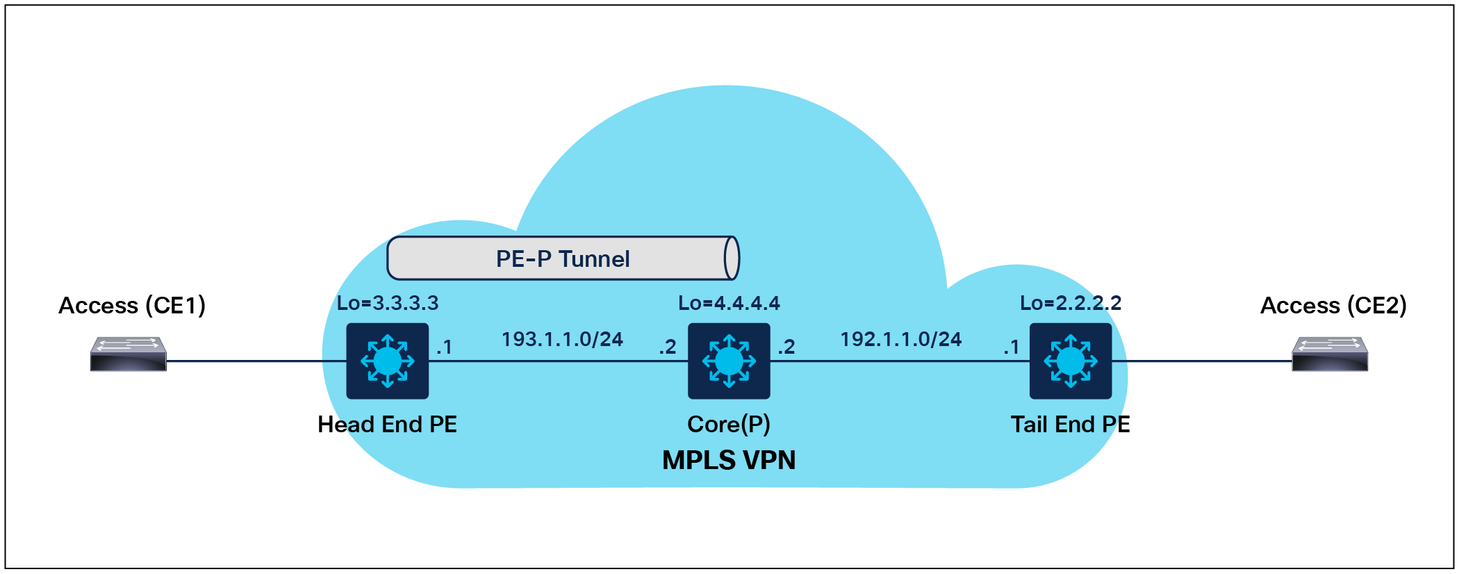
MPLS TE PE-to-P tunnel Deployment Overview
1. Interface parameter and backbone IGP MPLS TE configuration
| Core (P) |
Tail end PE |
|
| interface Port-channel30 no switchport ip address 193.1.1.1 255.255.255.0 ip ospf 1 area 0 mpls ip mpls traffic-eng tunnels ip rsvp bandwidth
interface Loopback0 ip address 3.3.3.3 255.255.255.255 ip ospf 1 area 0
router ospf 1 router-id 3.3.3.3 nsr nsf mpls traffic-eng router-id Loopback0 mpls traffic-eng area 0 |
interface Port-channel30 no switchport ip address 193.1.1.2 255.255.255.0 ip ospf 1 area 0 mpls ip mpls traffic-eng tunnels ip rsvp bandwidth
interface Port-channel50 no switchport ip address 192.1.1.2 255.255.255.0 ip ospf 1 area 0 mpls ip mpls traffic-eng tunnels ip rsvp bandwidth
interface Loopback0 ip address 4.4.4.4 255.255.255.255 ip ospf 1 area 0 router ospf 1 router-id 4.4.4.4 nsr nsf mpls traffic-eng router-id Loopback0 mpls traffic-eng area 0 |
interface Port-channel50 no switchport ip address 192.1.1.1 255.255.255.0 ip ospf 1 area 0 mpls ip mpls traffic-eng tunnels ip rsvp bandwidth
interface Loopback0 ip address 2.2.2.2 255.255.255.255 ip ospf 1 area 0
router ospf 1 router-id 2.2.2.2 nsr nsf mpls traffic-eng router-id Loopback0 mpls traffic-eng area 0 |
2. TE tunnel configuration
| Head end PE |
Core (P) |
Tail end PE |
| mpls traffic-eng tunnels mpls ldp graceful-restart mpls ldp discovery targeted-hello accept mpls ldp router-id Loopback0 force ip rsvp signalling hello graceful-restart mode help-neighbor mpls traffic-eng nsr
interface Tunnel100 ip unnumbered Loopback0 tunnel mode mpls traffic-eng tunnel destination 2.2.2.2 tunnel mpls traffic-eng autoroute announce tunnel mpls traffic-eng priority 7 7 tunnel mpls traffic-eng bandwidth 500 tunnel mpls traffic-eng path-option 1 dynamic |
mpls traffic-eng tunnels mpls ldp graceful-restart mpls ldp discovery targeted-hello accept mpls ldp router-id Loopback0 force ip rsvp signalling hello graceful-restart mode help-neighbor mpls traffic-eng nsr |
mpls traffic-eng tunnels mpls ldp graceful-restart mpls ldp discovery targeted-hello accept mpls ldp router-id Loopback0 force ip rsvp signalling hello graceful-restart mode help-neighbor mpls traffic-eng nsr |
MPLS inter-AS options refer to the various methods used to connect multiple autonomous systems (ASes) in a service provider network using MPLS technology. MPLS inter-AS options are used to enable seamless communication between customer sites that are in different ASes, while maintaining scalability and efficient use of network resources.
Several MPLS inter-AS options are supported by Catalyst 9000 switches, including the following.
● Option A: Also known as back-to-back VPN, this option is used when the two ASes are controlled by a single service provider. In this option, each AS has its own VPN, and the VPNs are connected using a VPN tunnel across the backbone.
● Option B: Also known as inter-AS L3VPN, this option is used when the two ASes are controlled by different service providers. In this option, each AS has its own MPLS network and L3VPN, and the L3VPNs are connected using BGP between the two service providers.
● Option C: Inter-AS option C is a network architecture used to connect two separate ASes through an MPLS network while maintaining distinct and isolated routing policies within each AS. This approach is designed to ensure that the internal routing decisions and policies of ASes do not leak or interfere with one another, while still allowing seamless data exchange between them.
● Option AB: In inter-AS option AB, each service provider is responsible for its own MPLS network and the customer VPNs that it supports. The two providers exchange VPN routing information using BGP and Multiprotocol BGP (MP-BGP) between their ASes.
The provider AS Border Routers (ASBRs) perform label switching for the VPN traffic that is passed between the two networks. The VPN traffic is labeled with both the ingress and egress provider ASBR addresses, allowing the egress ASBR to properly identify the destination VPN and forward the traffic to the appropriate VPN customer in its network.
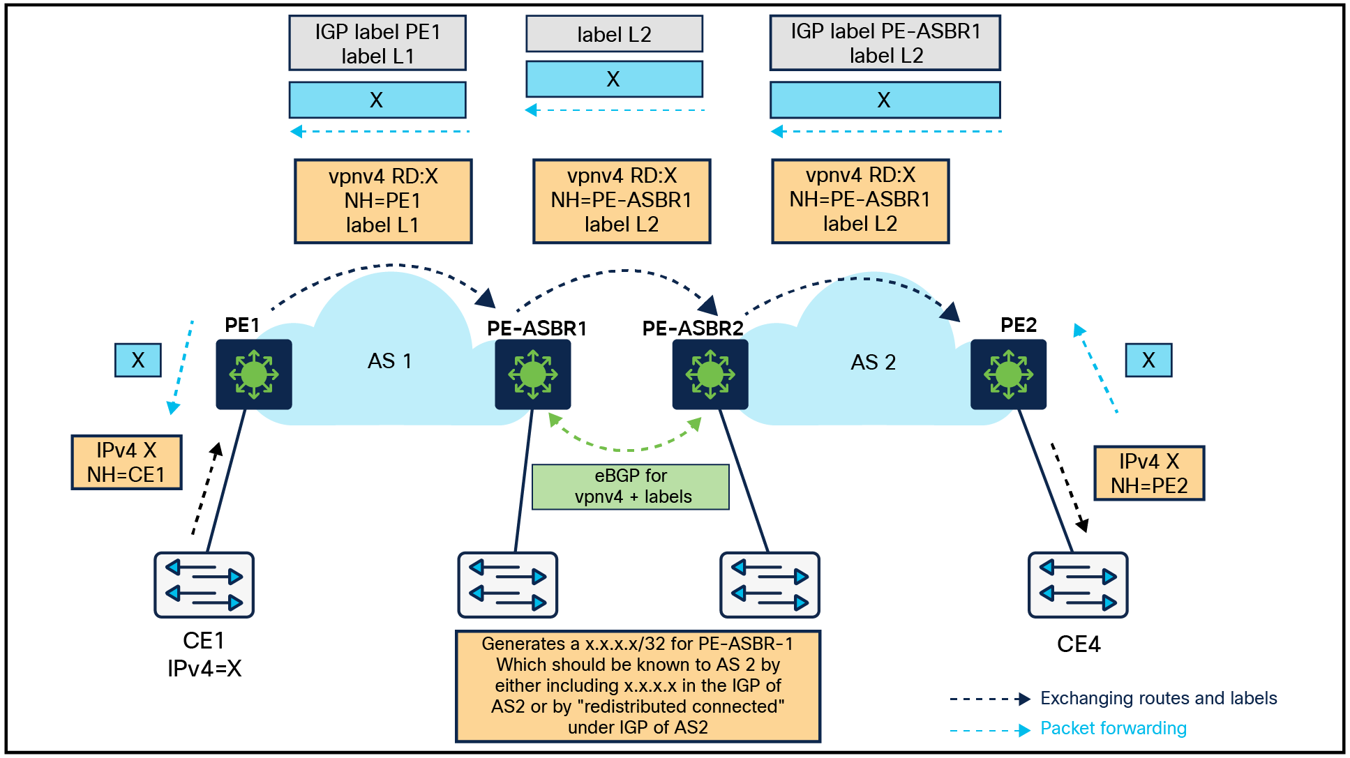
Inter-AS MPLS VPN Overview
With this option the ASBRs peer with each other using external BGP (eBGP) sessions. An ASBR also functions as a PE router and peers with every PE router in its AS. The ASBR does not hold any VRFs but holds all or a subset of VPNv4 routes from the PE router that need to be passed to other ASes. VPNv4 routes are kept unique in the ASBR using route-distinguisher, and they are filtered using route-targets. The ASBRs exchange VPNv4 routes and VPN labels using eBGP.
Inter-AS option A configuration
Inter-AS option A
| PE1 |
PE-ASBR1 |
PE-ASBR2 |
PE2 |
| vrf definition A vrf definition B ! |
<VRF “A” and ”B” have to be defined >
! address-family ipv4 vrf A neighbor 192.168.1.2 remote-as 65001 neighbor 192.168.1.2 activate ! address-family ipv4 vrf B neighbor 192.168.2.2 remote-as 65001 neighbor 192.168.2.2 activate |
<VRF “A” and ”B” have to be defined >
! address-family ipv4 vrf A neighbor 192.168.1.2 remote-as 65000 neighbor 192.168.1.2 activate ! address-family ipv4 vrf B neighbor 192.168.2.2 remote-as 65000 neighbor 192.168.2.2 activate |
vrf definition A vrf definition B ! |
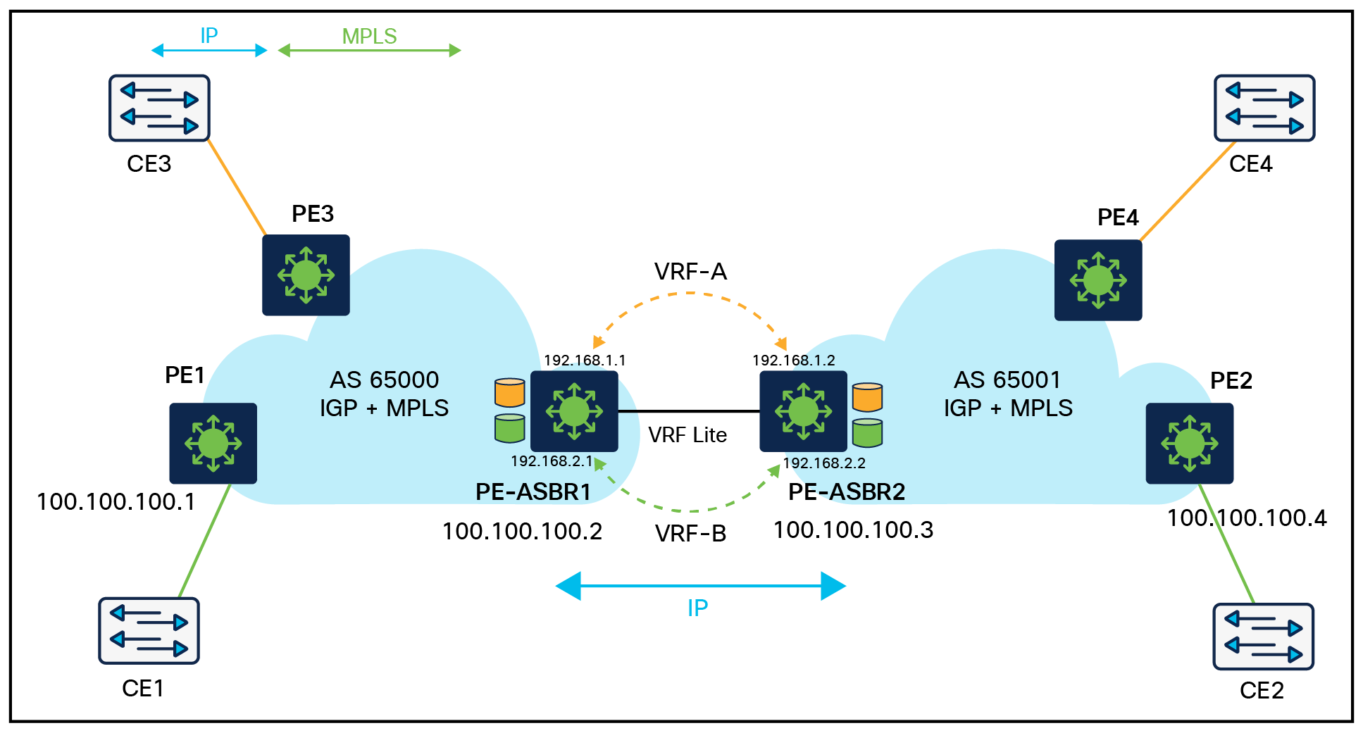
Inter-AS option AB configuration
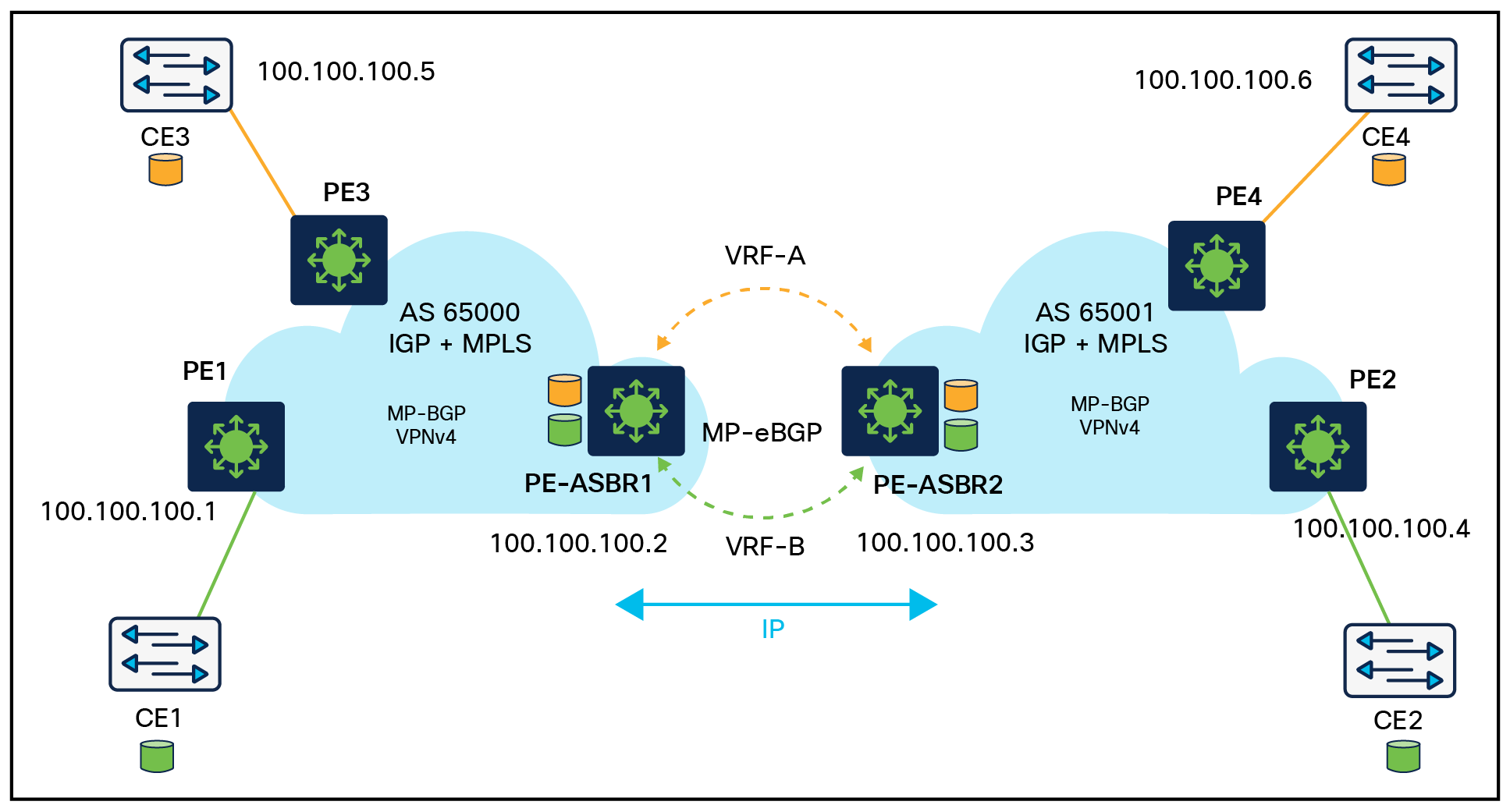
Inter-as option AB Deployment Overview
| PE-ASBR1 |
PE-ASBR2 |
| ip vrf cust-1 rd 100:10001 route-target export 100:1 route-target import 100:1 route-target import 200:1 inter-as-hybrid next-hop 100.100.100.3 ! ip vrf cust-2 rd 100:20001 route-target export 100:2 route-target import 100:2 route-target import 200:2 inter-as-hybrid next-hop 170.1.1.2 ! router bgp 65000 neighbor 100.100.100.1 remote-as 65000 neighbor 100.100.100.3 remote-as 65001 ! address -family ipv4 neighbor 100.100.100.1 activate neighbor 100.100.100.3 activate ! address -family vpnv4 neighbor 100.100.100.1 activate neighbor 100.100.100.1 send-community both neighbor 100.100.100.3 activate neighbor 100.100.100.3 send-community both neighbor 100.100.100.3 inter-as-hybrid ! address -family ipv4 vrf cust-1 redistribute connected ! address -family ipv4 vrf cust-2 redistribute connected |
ip vrf cust-1 rd 100:10001 route-target export 100:1 route-target import 100:1 route-target import 200:1 inter-as-hybrid next-hop 100.100.100.2 ! ip vrf cust-2 rd 100:20001 route-target export 100:2 route-target import 100:2 route-target import 200:2 inter-as-hybrid next-hop 170.1.1.2 ! router bgp 65001 neighbor 100.100.100.4 remote-as 65000 neighbor 100.100.100.2 remote-as 65001 ! address -family ipv4 neighbor 100.100.100.4 activate neighbor 100.100.100.2 activate ! address -family vpnv4 neighbor 100.100.100.2 activate neighbor 100.100.100.2 send-community both neighbor 100.100.100.4 activate neighbor 100.100.100.4 send-community both neighbor 100.100.100.2 inter-as-hybrid ! address -family ipv4 vrf cust-1 redistribute connected ! address -family ipv4 vrf cust-2 redistribute connected |
This section describes some of the typical campus network designs. Catalyst 9000 switches can run MPLS features at the access, distribution, and core layers.
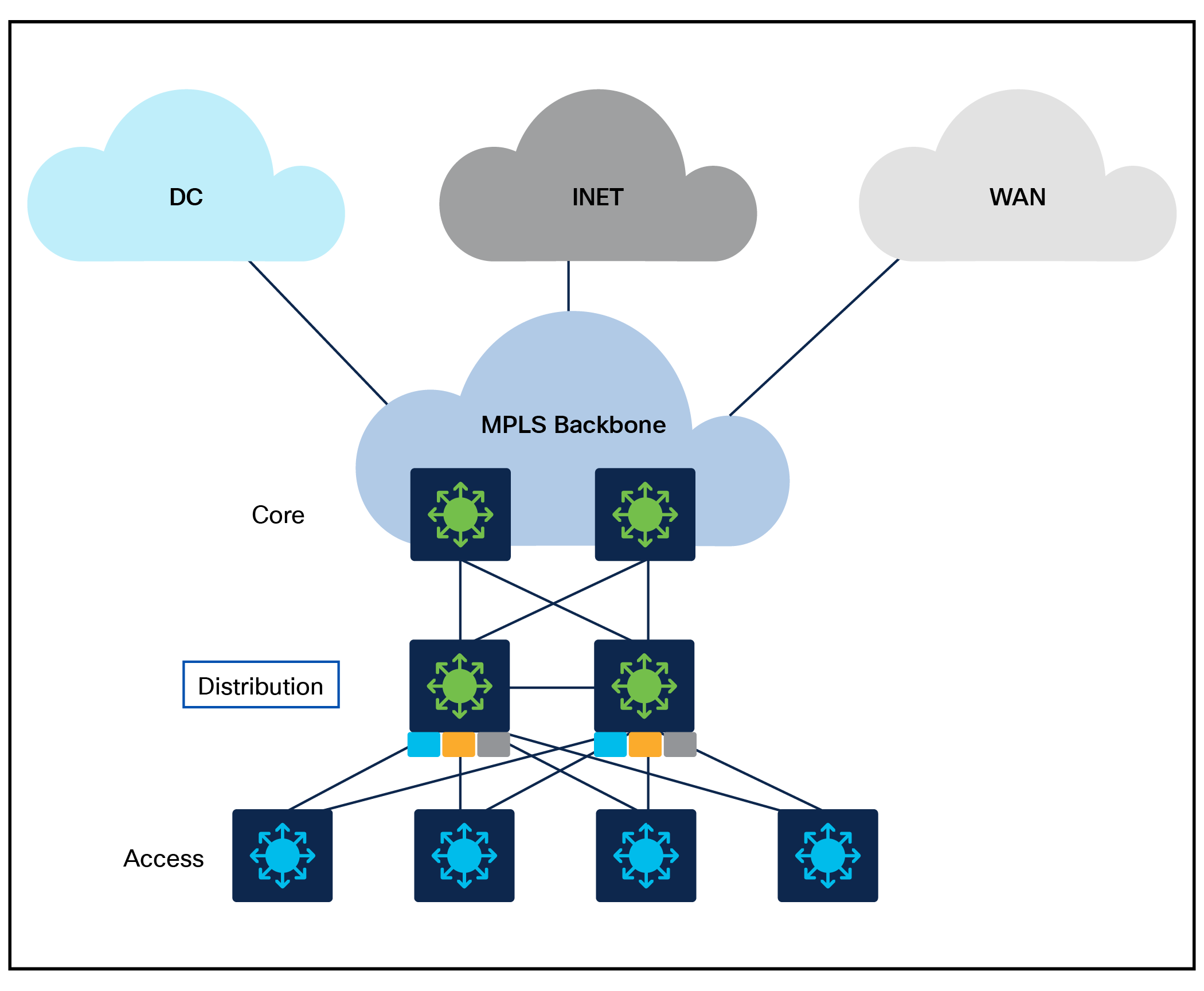
Campus network with MPLS at the core
In an MPLS network, the PE routers are typically responsible for performing VRF-based segmentation and providing VPN services to customers. However, in some cases, it may be possible to use core devices as PE devices and perform VRF-based segmentation at the core layer. With this approach, the core devices act as PE devices and are responsible for providing VPN services to customers, while also performing the routing and switching functions of the core network. VRF-based segmentation is performed at the core layer, with each VRF representing a separate VPN. The core devices maintain separate forwarding tables for each VRF, allowing traffic to be separated and forwarded to the appropriate VPN.
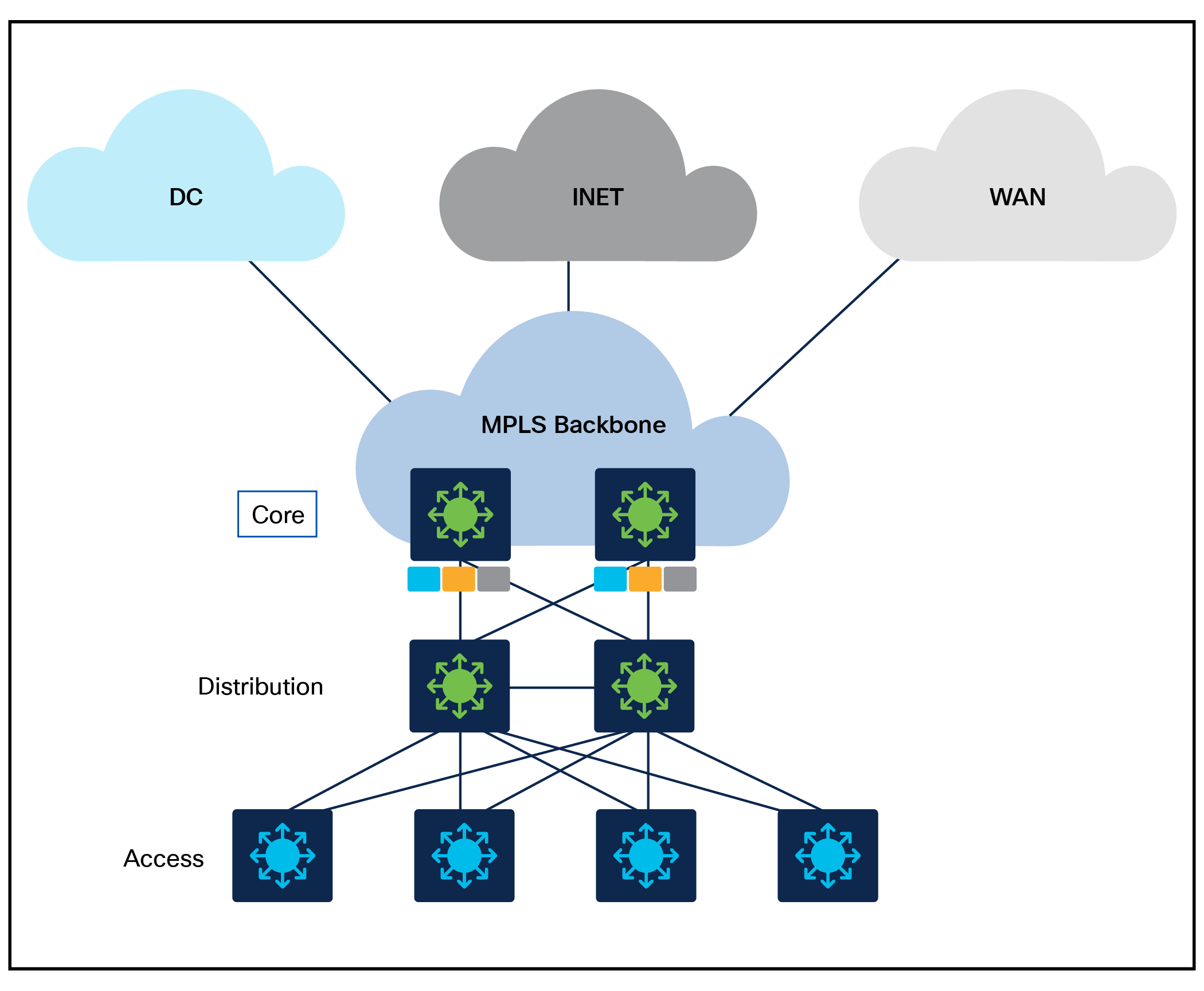
MPLS at the distribution layer
Campus network with MPLS at the distribution layer
With MPLS enabled at the distribution layer, VRF-based segmentation can be performed to create separate VPNs for different business units or departments within the organization. Core routers can act as P routers, extending the MPLS to DC, INET, and WAN via the MPLS backbone and providing additional capabilities such as traffic engineering and VPNs without requiring additional hardware or complexity at the core layer. The MPLS backbone can be self-managed or managed via a provider.
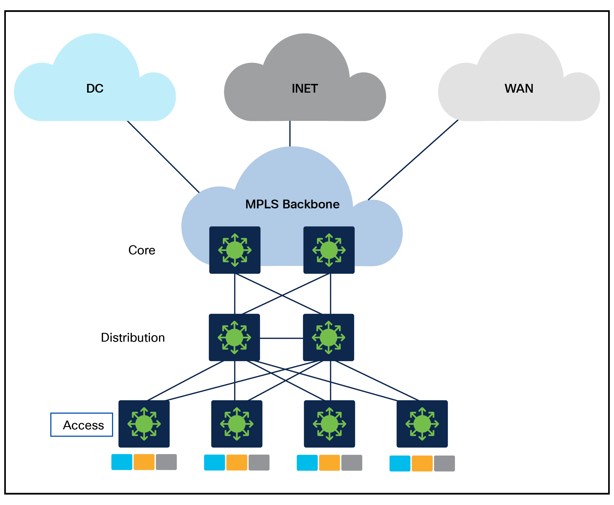
Campus network with MPLS at the access layer
In this scenario, MPLS is enabled at the access layer, for routed access with MPLS. This design involves segmentation right at the access layer, providing much more security by isolating the networks at the user gateway. In this scenario, the distribution and core routers act as P/PE routers.
Any of the designs outlined above can be a collapsed core environment based on the number of access, aggregation, and core nodes, thereby eliminating the distribution layer.
EoMPLS (point-to-point Layer 2 extension)
At times, there is a need to extend the Layer 2 domain across the MPLS domain. To extend the Layer 2 domain, the Catalyst 9000 switches support EoMPLS and VPLS solutions.
EoMPLS solution with point-to-point Layer 2 extension
The EoMPLS solution can be used when there is a need for point-to-point Layer 2 extension. EoMPLS provides flexibility of deployment because it can be used to provide Ethernet connectivity at the access layer between switches at geographically dispersed sites. The EoMPLS tunnel can be established between the access switches and can be terminated at the distribution layer.
At the distribution layer, the EoMPLS tunnel can be terminated on a switch acting as a PE device. The PE device can then perform the necessary functions, such as encapsulating Ethernet frames with MPLS labels and routing them over the MPLS network. The distribution layer switches can also perform functions such as traffic shaping, policing, and QoS enforcement.
VPLS (point-to-multipoint Layer 2 extension)
VPLS solution with point-to-multipoint Layer 2 extension
VPLS provides more flexibility by providing point-to-multipoint solutions. At the access layer, VPLS can be used to connect the Ethernet switches at different sites to form a single virtual LAN. The VPLS service provider network will then be responsible for transporting Ethernet frames between the customer sites. Each site will have a VPLS pseudowire connecting the CE switch to the PE switch, which will encapsulate Ethernet frames with VPLS headers and transport them over the service provider network.
At the distribution layer, the PE switches will perform the necessary VPLS functions, such as learning the MAC addresses, forwarding Ethernet frames over the VPLS pseudowires, and maintaining a consistent view of the VPLS domain across the network.
Hierarchical VPLS (H-VPLS)
When multipoint-to-multipoint connectivity is required across multiple sites in a scalable and resilient manner, H-VPLS can be deployed. H-VPLS is used in situations where a traditional Layer 2 network does not provide the required scale or flexibility, or where Layer 3 routing is not practical due to the complexity of the network or the requirements of the applications being used.
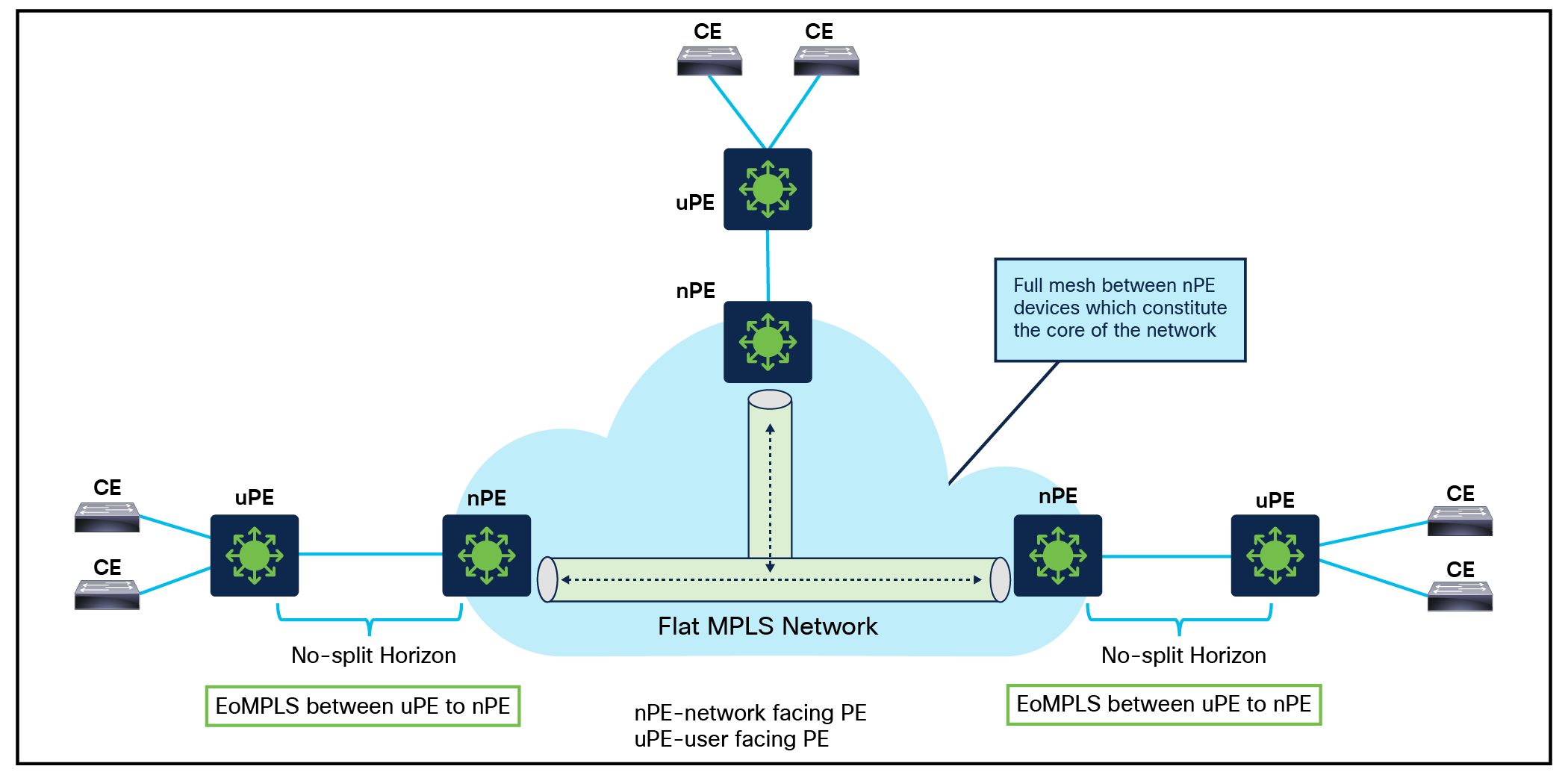
Hierarchical VPLS Solution
H-VPLS uses a hierarchical architecture that separates the core and access layers of the network, allowing for efficient forwarding of Ethernet frames between sites. The core layer is responsible for forwarding traffic between sites, while the access layer is responsible for connecting end devices to the network.
The network provider edge (NPE) devices form a hierarchical structure that provides connectivity between the customer sites, while the user provider edge (UPE) devices provide connectivity between the customer sites and the H-VPLS network. The NPE devices use a peer-to-peer mesh network to interconnect with each other, and they exchange Layer 2 MAC address information to build a distributed MAC table for the entire H-VPLS network. The UPE devices connect to the NPE devices using a point-to-point connection, and they communicate with the NPE devices to exchange MAC address information for the customer sites.
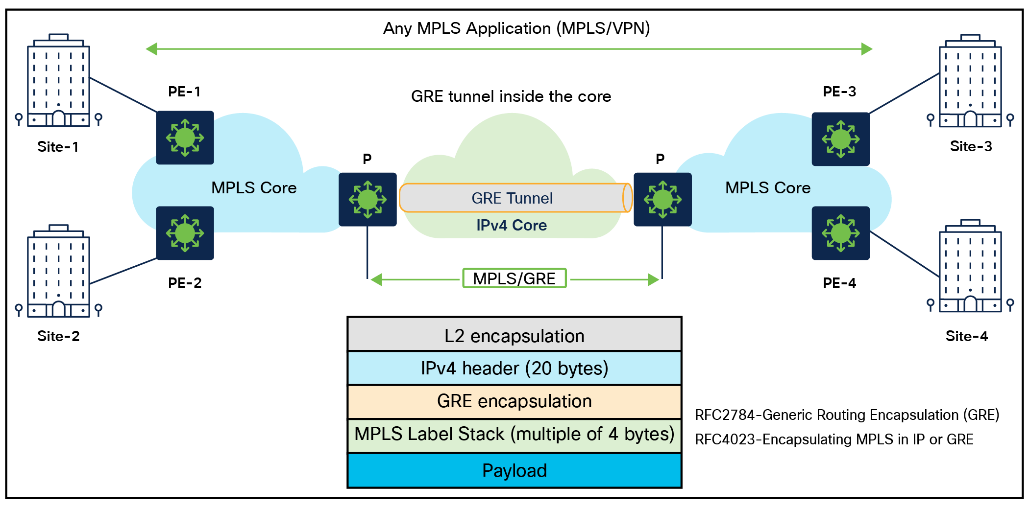
MPLS over GRE Solution
The MPLS over GRE feature provides a mechanism for tunneling MPLS packets over a non-MPLS network. The MPLS packets are encapsulated within the GRE tunnel packets, and the encapsulated packets traverse the non-MPLS network through the GRE tunnel. When GRE tunnel packets are received at the other side of the non-MPLS network, the GRE tunnel packet header is removed and the inner MPLS packet is forwarded to its destination. The core network between the endpoints of the GRE tunnel uses the intermediate system-to-intermediate system (IS-IS) or OSPF routing protocol, whereas the GRE tunnel uses OSPF or Enhanced Interior Gateway Routing Protocol (EIGRP). The Catalyst 9000 switches support the following tunneling options for Layer 2/Layer 3 MPLS services:
● PE-to-PE tunneling
● P-to-PE tunneling
● P-to-P tunneling
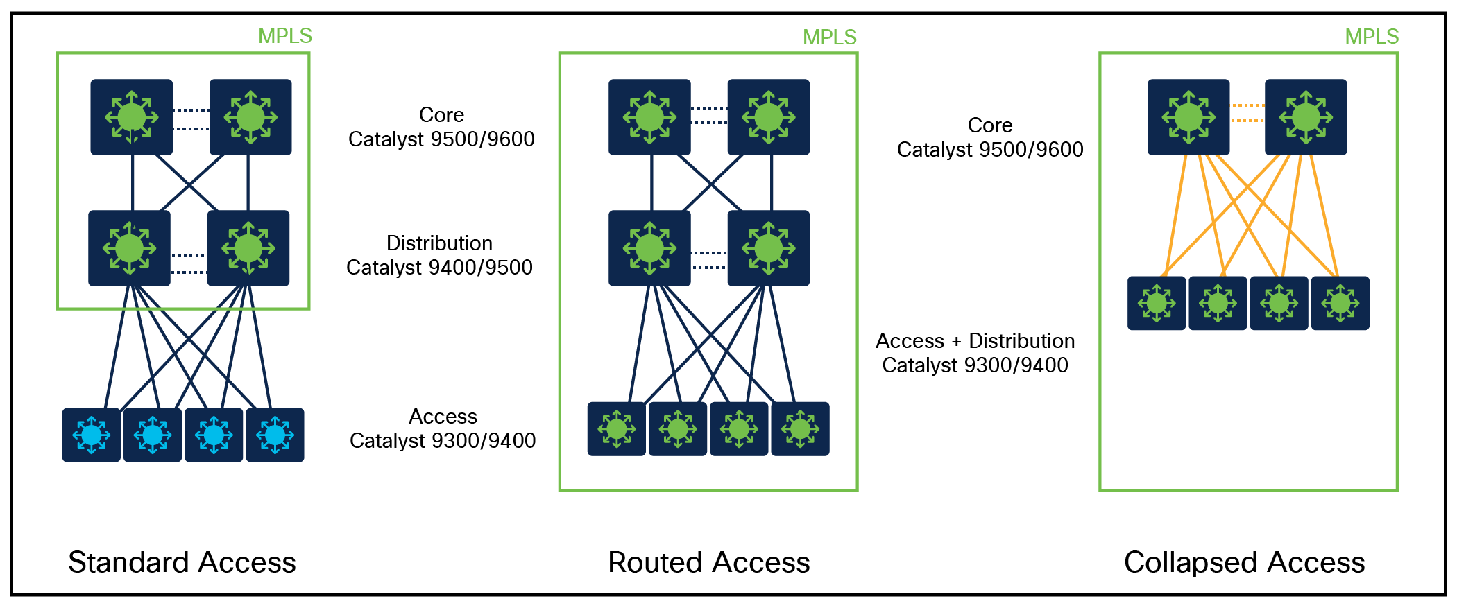
The MPLS architecture has many different deployment scenarios that apply to different use cases. The topology that works best depends on the use case.
This section considers the following major topologies:
● Standard access
● Routed access
● Standard access
● Routed access
● Collapsed access
Key design factors: VRF/route scale, port density, MPLS features, fixed vs. modular in access/backbone

Standard and routed access Design Overview
When designing an MPLS network with standard access and routed access, there are several key considerations to keep in mind:
Standard access design considerations:
● Scalability: Design the MPLS network with scalability in mind to accommodate the growth of standard access connections. Consider potential future expansion.
● Traffic engineering: Employ MPLS-TE techniques to optimize traffic flows, maximize network utilization, and efficiently allocate resources.
Standard, routed and collapsed access Design Overview
Routed access design considerations
● Addressing and IP subnets: Plan the addressing scheme and IP subnets for the routed access connections, considering address aggregation within the MPLS network.
● Route distribution: Determine the appropriate method for distributing routes between the CE and PE devices. This can involve static routing, dynamic routing protocols, or MPLS-specific mechanisms like BGP/MPLS VPN.
MACsec for secure MPLS transport
MACsec is a security protocol used to secure traffic on Ethernet links. It provides confidentiality and integrity for the Ethernet frames transmitted over the link by encrypting the frames using symmetric-key cryptography.
When used with point-to-point MPLS links, MACsec can provide end-to-end security for MPLS traffic. In this scenario, Ethernet frames are encapsulated in MPLS packets and then the MACsec security protocol is implemented on top of the MPLS packet at the PHY (physical) layer of a network device to provide security for data transmitted over Ethernet links. The advantage of using MACsec with point-to-point MPLS links is that it provides end-to-end security for MPLS traffic without requiring any changes to the MPLS network itself. This makes it a simple and effective way to secure MPLS traffic over point-to-point links. The UADP-based Catalyst 9000 switches support MACsec Key Agreement (MKA) MACsec with MPLS starting with IOS XE 17.11.1.
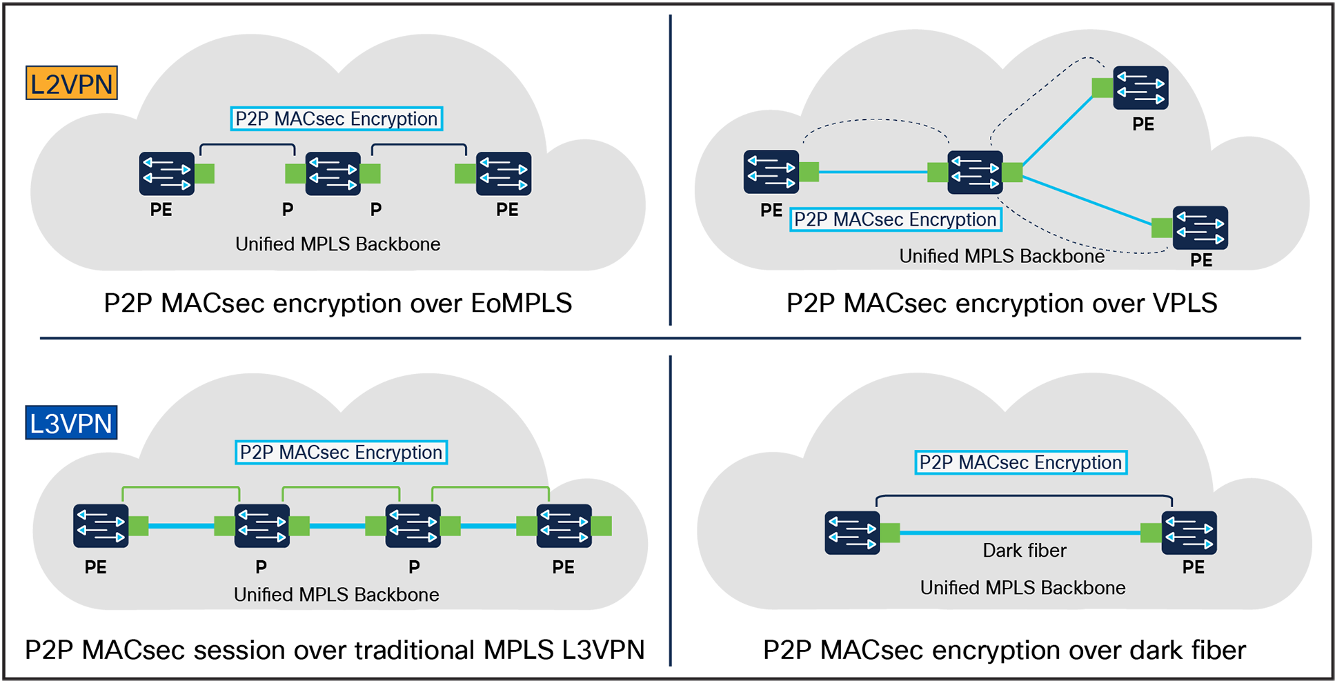
MACsec over MPLS Overview
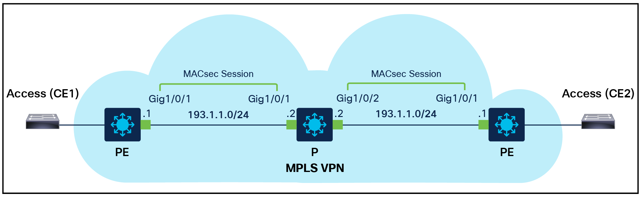
MACsec over MPLS Deployment Overview
| PE |
P |
PE |
| interface gig1/0/1 no switchport ip address 193.1.1.1 255.255.255.0 macsec network-link mpls ip mka policy gcm_256_policy
mka policy gcm_256_policy macsec-cipher-suite gcm-aes-256 |
interface 1/0/1 no switchport ip address 193.1.1.2 255.255.255.0 macsec network-link mpls ip mka policy gcm_256_policy
interface 1/0/2 no switchport ip address 192.1.1.2 255.255.255.0 macsec network-link mpls ip mka policy gcm_256_policy
mka policy gcm_256_policy macsec-cipher-suite gcm-aes-256 |
interface gig1/0/1 no switchport ip address 192.1.1.1 255.255.255.0 macsec network-link mpls ip mka policy gcm_256_policy
mka policy gcm_256_policy macsec-cipher-suite gcm-aes-256 |
Flexible NetFlow for MPLS monitoring
Flexible NetFlow is a powerful technology that allows for comprehensive network traffic monitoring and analysis. By implementing this solution, you can gain critical insights into MPLS traffic flows and enhance your network management capabilities. The Catalyst 9000 switches support the following capabilities:
Ingress Flexible NetFlow on MPLS (IP level)
Allows the capture of IP flow information for packets undergoing MPLS label imposition that are entering the MPLS network. These packets arrive on a router as IP packets and are transmitted as MPLS packets. This feature can be enabled by configuring an ingress flow monitor for IPv4 and IPv6 traffic at the CE-facing side of the PE node.
Egress Flexible NetFlow on MPLS (IP level)
Allows the capture of IP flow information for packets undergoing MPLS label imposition that are exiting the MPLS network. These packets arrive on a router as MPLS packets and are transmitted as IP packets. The feature can be enabled by configuring an egress flow monitor for IPv4 and IPv6 traffic at the CE-facing side of the PE node.
The table below provides a feature matrix for major MPLS features across the Catalyst 9000 switching family.
| Feature |
9300/ 9300X |
9400/ 9400X |
9500 |
9500H |
9600 |
9500X/ 9600X |
| MPLS |
ü |
ü |
ü |
ü |
ü |
ü |
| L3VPN |
ü |
ü |
ü |
ü |
ü |
ü |
| L2VPN |
ü |
ü |
ü |
ü |
ü |
ü |
| 6PE |
ü |
ü |
ü |
ü |
ü |
ü |
| 6VPE |
ü |
ü |
ü |
ü |
ü |
ü |
| EoMPLS |
ü |
ü |
ü |
ü |
ü |
ü |
| VPLS |
ü |
ü |
ü |
ü |
ü |
* |
| L2VPN PW |
ü |
ü |
ü |
ü |
ü |
ü |
| VPLS PW |
ü |
ü |
ü |
ü |
ü |
* |
| H-VPLS |
ü |
ü |
ü |
ü |
ü |
* |
| Inter-AS |
ü |
ü |
ü |
ü |
ü |
ü |
| Inter-AS |
ü |
ü |
ü |
ü |
ü |
* |
| Inter-AS |
ü |
ü |
ü |
ü |
ü |
* |
| Inter-AS |
ü |
ü |
ü |
ü |
ü |
* |
| BGP send-label |
ü |
ü |
ü |
ü |
ü |
* |
| Seamless MPLS |
ü |
ü |
ü |
ü |
ü |
* |
| mVPN |
ü |
ü |
ü |
ü |
ü |
* |
| MPLSoGRE |
ü |
ü |
ü |
ü |
ü |
* |
| MPLS TE |
ü |
ü |
ü |
ü |
ü |
* |
| MPLS TE EoMPLS preferred path |
ü |
ü |
ü |
ü |
ü |
* |
| MPLS TE forwarding adjacency |
ü |
ü |
ü |
ü |
ü |
* |
| MPLS TE load balancing |
ü |
ü |
ü |
ü |
ü |
* |
| MPLS TE inter area |
ü |
ü |
ü |
ü |
ü |
* |
Multiprotocol Label Switching Configuration Guide, Cisco IOS XE Dublin 17.12.x (Catalyst 9300 Series Switches):
Multiprotocol Label Switching Configuration Guide, Cisco IOS XE Dublin 17.12.x (Catalyst 9400 Switches):
Multiprotocol Label Switching Configuration Guide, Cisco IOS XE Dublin 17.12.x (Catalyst 9500 Switches): https://www.cisco.com/c/en/us/td/docs/switches/lan/catalyst9500/software/release/17-12/configuration_guide/mpls/b_1712_mpls_9500_cg.pdf.
Multiprotocol Label Switching Configuration Guide, Cisco IOS XE Dublin 17.12.x (Catalyst 9600 Switches):