Connecting and Troubleshooting IoT Devices Using Asynchronous Serial Interfaces White Paper
Available Languages
Bias-Free Language
The documentation set for this product strives to use bias-free language. For the purposes of this documentation set, bias-free is defined as language that does not imply discrimination based on age, disability, gender, racial identity, ethnic identity, sexual orientation, socioeconomic status, and intersectionality. Exceptions may be present in the documentation due to language that is hardcoded in the user interfaces of the product software, language used based on RFP documentation, or language that is used by a referenced third-party product. Learn more about how Cisco is using Inclusive Language.
Asynchronous serial interfaces such as EIA RS-232, RS-485, and RS-422 are used across multiple industries. Devices such as Remote Terminal Units (RTUs), Programmable Logic Controllers (PLCs), Point-Of-Sale terminals (POS), modems, and routers all use serial interfaces to communicate. Due to the limitations of the initial standard and subsequent revisions, serial interfaces have a large number of physical pinouts, so it is often incredibly challenging to get devices from different manufacturers to communicate over these interfaces. This white paper describes how to connect these devices to Cisco® IoT routers. It also discusses various serial interface use cases, configuration, and troubleshooting. Table 1 provides a summary of various Cisco IoT gateways and the serial interfaces they support.
Table 1. Cisco IoT serial ports and platforms at a glance
| Serial interface type IoT products |
RS-232 (EIA/TIA-561) |
RS-232 (EIA/TIA-232) |
RS-485 Full and half duplex |
RS-485 Full and half duplex |
Cisco console serial ports Mini-USB or RJ45 – RS-232 with Cisco proprietary console pinout |
|
| Connector type |
RJ45 DTE |
RJ45 DCE |
DB9 Female DCE |
RJ45 |
DB9 Female |
Mini-USB/RJ45 |
| IR1101 |
Async 0/2/0 |
N/A |
N/A |
N/A |
N/A |
Mini-USB |
| IR807 |
Async 0 |
Async 1 |
N/A |
N/A |
N/A |
Mini-USB |
| IR809 |
Async 1 |
Async 0 |
N/A |
Async 0 |
N/A |
Mini-USB |
| IR829 |
Async 1 |
Async 0 |
N/A |
Async 0 |
N/A |
Mini-USB |
| IR509 |
Serial 1 |
Serial 0 |
N/A |
Serial 0 |
N/A |
RJ45 |
| IR510 |
Serial 1 |
Serial 0 |
N/A |
Serial 0 |
N/A |
RJ45 |
| CGR1240 |
N/A |
Async 1/1 Async 1/2 |
N/A |
Async 1/1 Async 1/2 |
N/A |
RJ45 |
| CGR1120 |
N/A |
N/A |
Async 1/1 Async 1/2 |
N/A |
Async 1/1 Async 1/2 |
RJ45 |
1. Asynchronous serial interface basics
1.1. Types of connections
Commonly used asynchronous serial interfaces are of three types: EIA/TIA RS-232, RS-422, and RS-485.
RS-232 is by far the most popular interface used on devices such as PC COM ports as well as networking, consumer, and industrial devices for distances up to 15 meters (50 feet). The maximum data rates on RS-232 can reach up to 20 Kbps. It comes in different physical layouts, including RJ45, DB9, and DB25.
The second interface type is RS-422. It offers much better speed and noise immunity, as well as longer cable length. It was intended to be a replacement for RS-232C. RS-422 interfaces allow data rates up to 10 Mbps. At reduced speed, they can operate at distances up to 1500 meters (0.9 mile). RS-422 also supports multidrop, enabling multiple RS-422 devices to be connected on a single interface.
The third interface type is RS-485. It can also be used for data rates up to 10 Mbps. At reduced speed, it can operate at distances up to 1200 meters (0.75 mile). RS-485 interfaces support a multidrop, multimaster serial bus, which is an improvement over RS-422 interfaces. RS-485 interfaces need only two wires for half-duplex communication. For full duplex, four wires are needed.
1.1.1. RS-232
Most Cisco routers natively support EIA/TIA RS-232 serial connections. RS-232 ports are of two types: Data Terminal Equipment (DTE) and Data Circuit Terminating Equipment (DCE). They have the same signal names and PINs, but the signal flow is the opposite. The output signals on a DTE port are inputs to a DCE port, and output signals on a DCE port are inputs to a DTE port. The signal names match each other and connect pin for pin. Signal flow is in the direction of the arrows. If devices require Carrier Detect (CD), it can be simulated by connecting Data Set Ready (DSR) and Data Carrier Detect (DCD) internally in the connector, thus obtaining CD from the remote Data Terminal Ready (DTR) signal.
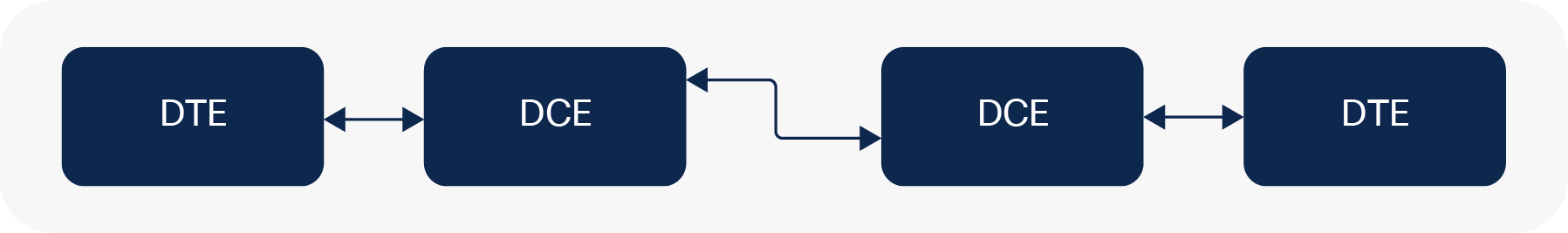
DTE and DCE ports in RS-232
1.1.2. RS-485
The RS-485 standard does not have a connector specified. Most vendors provide screw connectors. Most Cisco IoT routers have native RJ45 RS-485 serial ports that allow connectivity to RS-485 devices. For routers such as the Cisco 1101 Industrial Integrated Services Router (IR1101) that do not have native RS-485 interfaces, RS-232 to RS-485 adapters can be used. Some examples of adapters are shown below. Apart from SEL-2886, other adapter models are provided for reference only and haven’t been tested in a Cisco lab.
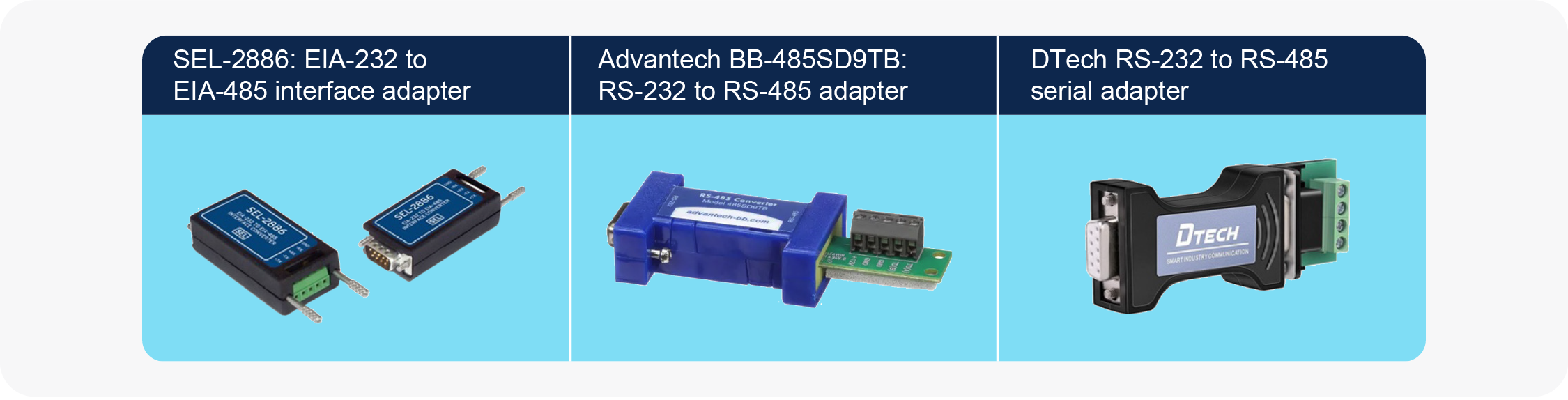
RS-232 to RS-485 adapters
1.1.3. RS-422
To connect RS-422 devices to a Cisco RS-232 serial port, commonly available RS-422 to RS-232 adapters can be used. Most RS-232 to RS-485 adapters also support RS-422. Please reference the RS-485 adapters in the previous section.
1.2. Serial connector types
Cisco routers provide either RJ45 or DB9 connectors to connect serial devices. Most Cisco IoT devices use RJ45 connectors, except the Cisco 1120 Connected Grid Router (CGR1120). Figure 3 shows the RJ45 ports used on Cisco routers.
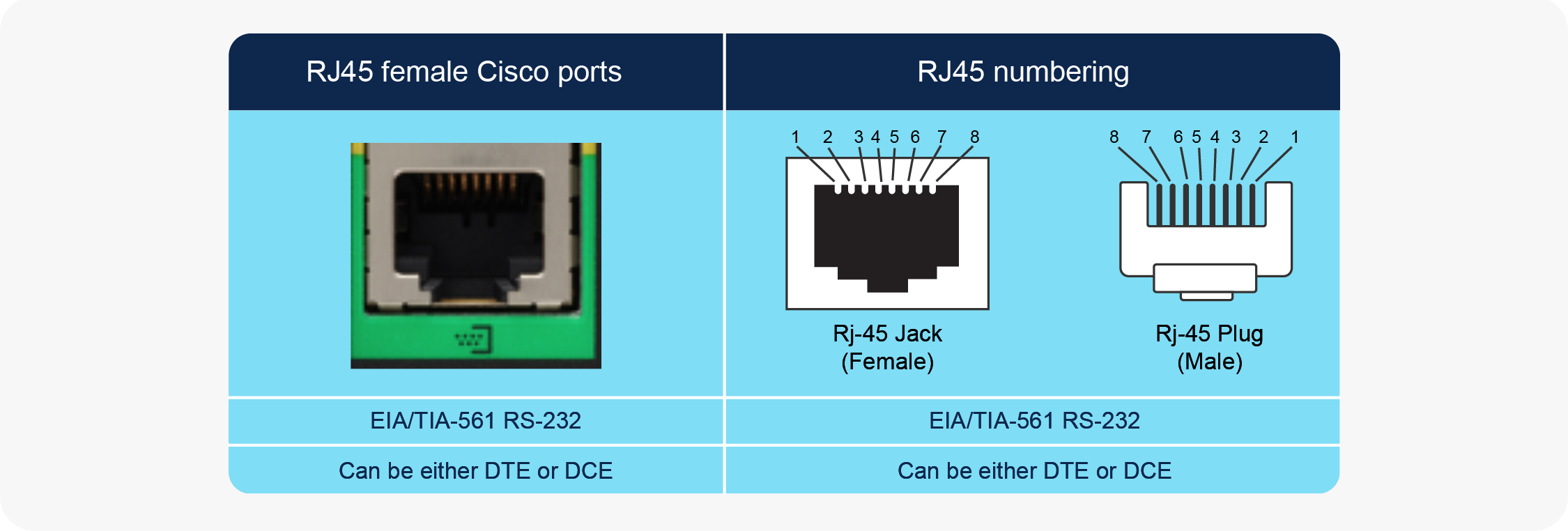
Cisco RJ45 ports
Another standard interface is DB9, as shown in Figure 4.
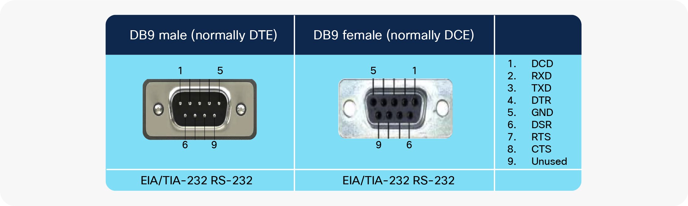
DB9 connector
1.3. Connecting RS-232 serial devices
1.3.1. DTE or DCE RS-232 ports
A straight cable should be used for connecting DTE interfaces to DCE interfaces.
1.3.2. Null modem (crossover) connections
Use a null modem configuration/adapter for connecting a DTE interface to a DTE interface or a DCE interface to a DCE interface.
1.4. Connecting serial devices to Cisco RJ45 female serial interfaces
1.4.1. Basics
Use a straight Ethernet cable, as shown in Figure 5, to connect serial RJ45 ports to adapters.
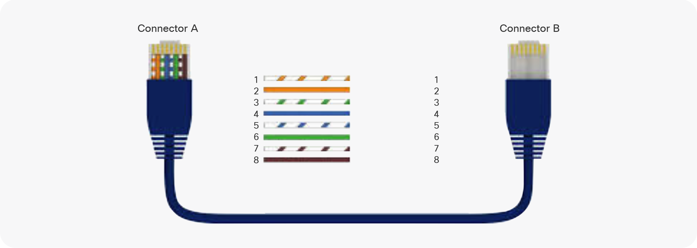
Straight cable
Figure 6 shows a configurable RJ45 to DB9 adapter that comes in both DB9 male and female configurations and can be used to connect RJ45 ports on Cisco IoT routers to various serial devices.

RJ45 to DB9 configurable adapter
Figure 7 shows an RJ45 conductor terminal that can also be used to connect serial devices to Cisco router serial ports in cases where there is a need to terminate wires directly and even for troubleshooting physical layer connectivity.

RJ45 male plug 8-conductor terminal
Figure 8 shows a DB9 breakout connector that can also be used when there is a need to terminate wires directly and even for troubleshooting physical layer connectivity.

DB9 breakout connector
1.4.2. RJ45 to DB9 adapters cabling diagrams
Figure 9 shows the pinout configuration for two RJ45 to DB9 female adapters. The left side shows the pinout for a straight connection, while the right side shows the pinout for a null modem connection. Note that RJ45 pins 1 through 9 are shown at the top and bottom of the DB9 adapter for understanding. All pins go to the same RJ45 adapter.
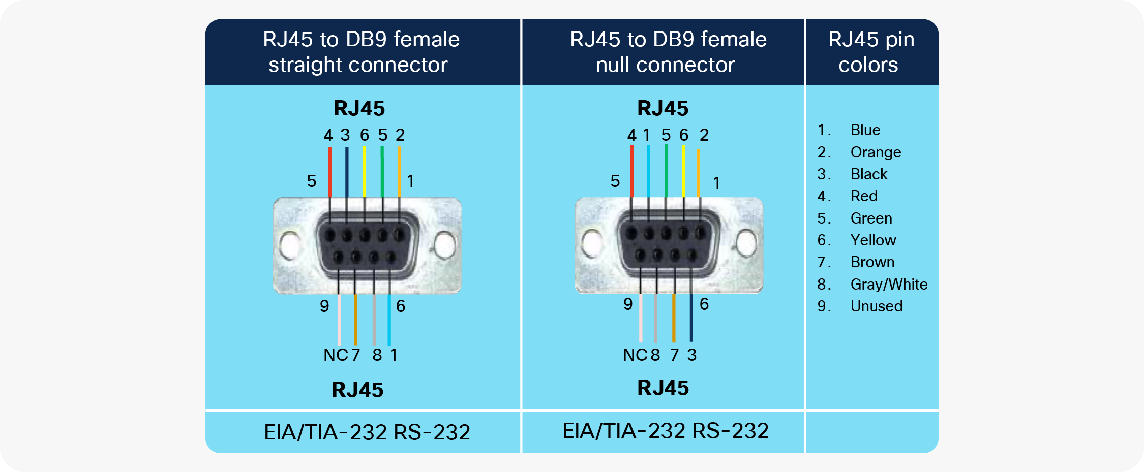
Pinouts for RJ45 to DB9 female adapters
Figure 10 shows the pinout configuration for RJ45 to DB9 male adapters. The left side shows the pinout for a straight connection, while the right side shows the pinout for a null modem connection. Note that RJ45 pins 1 through 9 are shown at the top and bottom of the DB9 adapter for understanding. All pins go to the same RJ45 adapter.

Pinouts for RJ45 to DB9 male adapters
RJ45 to DB9 null modems are generally not available off the shelf, and it is recommended that you build them using a modular RJ45 to DB9 adapter and connections, as shown in Figure 6.
DB9 null modem adapters exist off the shelf in all combinations of male and female connectors. If using one of these adapters, proper care must be taken to ensure that the end-to-end pinout matches the pinouts shown in Figures 9 and 10. Also note that in general DB9 male connectors are DTE and DB9 female connectors are DCE.
Standard serial port pinouts (RJ45 vs. DB9)
Table 2. Pinouts for serial connectors
| RJ45 EIA/TIA-561 standard |
DB9 EIA/TIA-232 standard |
Cisco console port |
|||
| RS-232 signal name direction) |
RJ45 DTE |
RJ45 DCE |
DB9-M-DTE (male) |
DB9-F-DCE (female) |
RJ45 DCE |
| DSR (DCE -> DTE) |
1 |
1 |
6 |
6 |
2 |
| DCD (DCE -> DTE) |
2 |
2 |
1 |
1 |
- |
| DTR (DTE -> DCE) |
3 |
3 |
4 |
4 |
7 |
| SG (GND) |
4 |
4 |
5 |
5 |
4, 5 |
| RXD (DCE -> DTE) |
5 |
5 |
2 |
2 |
3 |
| TXD (DTE -> DCE) |
6 |
6 |
3 |
3 |
6 |
| CTS (DCE -> DTE) |
7 |
7 |
8 |
8 |
1 |
| RTS (DTE -> DCE) |
8 |
8 |
7 |
7 |
8 |
Table 2 summarizes pinouts for various connectors. Table 3 summarizes the recommended cabling for connecting multiple serial interfaces.
Table 3. Cabling for connecting various port combinations
| Serial RS232 port-to-port connection types |
Cables and adapters required (based on EIA/TIA-561 RJ45 pinout) |
|
| RJ45 serial to RJ45 serial |
||
| RJ45-DTE |
RJ45-DCE |
Straight Ethernet cable |
| RJ45-DCE |
RJ45-DTE |
Straight Ethernet cable |
| RJ45-DTE |
RJ45-DTE |
[Straight Ethernet cable] + [RJ45/DB9-M straight adapter] + [RJ45/DB9-F crossover adapter] + [Straight Ethernet cable] |
| RJ45-DCE |
RJ45-DCE |
[Straight Ethernet cable] + [RJ45/DB9-F straight adapter] + [RJ45/DB9-M crossover adapter] + [Straight Ethernet cable] |
| RJ45 serial to DB9 serial |
||
| RJ45-DTE |
DB9-F-DCE |
[Straight Ethernet cable] + [RJ45/DB9-M straight adapter] |
| RJ45-DTE |
DB9-M-DTE |
[Straight Ethernet cable] + [RJ45/DB9-F crossover adapter] |
| RJ45-DCE |
DB9-F-DCE |
[Straight Ethernet cable] + [RJ45/DB9-M crossover adapter] |
| RJ45-DCE |
DB9-M-DTE |
[Straight Ethernet cable] + [RJ45/DB9-F straight adapter] |
| RJ45 serial to DB25 serial |
||
| RJ45-DTE |
DB25-F-DCE |
[Straight Ethernet cable] + [RJ45/DB25-M straight adapter] |
| RJ45-DTE |
DB25-M-DTE |
[Straight Ethernet cable] + [RJ45/DB25-F crossover adapter] |
| RJ45-DCE |
DB25-F-DCE |
[Straight Ethernet cable] + [RJ45/DB25-M crossover adapter] |
| RJ45-DCE |
DB25-M-DTE |
[Straight Ethernet cable] + [RJ45/DB25-F straight adapter] |
| Cables and adapters required (based on console port RJ45 pinout) |
||
| RJ45 serial to RJ45 console |
||
| RJ45-DTE |
RJ45-DCE-Console |
[Straight Ethernet cable] + [RJ45/DB9-M straight adapter] + [DB9-F/RJ45 blue Cisco console cable] |
| RJ45-DCE |
RJ45-DCE-Console |
[Straight Ethernet cable] + [RJ45/DB9-M crossover adapter] + [DB9-F/RJ45 blue Cisco console cable] |
1.4.3. Configuring line interfaces
Table 4 lists various configuration options for line interfaces. Care should be taken to ensure that these configuration parameters on router serial ports (such as speed, parity, etc.) match the configuration on the connected serial device.
Table 4. Configuration parameters for line interfaces
| Command |
Purpose |
Values |
| transport input |
Defines which protocols can be used to connect to a specific line. |
lapb-ta, lat, mop, none, pad, rlogin, ssh, telnet, udptn, v120 |
| transport output |
Determines the protocols that can be used for outgoing connections from a line. |
lapb-ta, lat, mop, none, pad, rlogin, ssh, telnet, udptn, v120 |
| transport preferred |
Specifies the protocol for the router to use if the user did not specify a protocol. |
lapb-ta, lat, mop, none, pad, rlogin, ssh, telnet, udptn, v120 |
| transport preferred none |
Prevents errant connection attempts. |
none |
| databits |
Configures the number of data bits in a character for a port. |
5 to 8 |
| exec-timeout |
Configures the inactive terminal timeout for a port. |
0 to 35791: Timeout in minutes |
| modem |
Configures the modem settings for a port. These settings are platform dependent and only one or more might be supported. |
CTS-Alarm: Alarm device that only uses Clear to Send (CTS) for call control DTR-active: Leave DTR low unless the line has an active incoming connection or EXEC Dialin: Configure line for a modern dial-in modem Host: Devices that expect an incoming modem call InOut: Configure line for incoming AND outgoing use of modem Printer: Devices that require DSR/CD active always-on: Configure line for a modern always-on modem answer-timeout: Set interval between raising DTR and CTS response autoconfigure: Automatically configure modem on line dtr-delay: Set interval during which DTR is held low onhold: Set the V.92 modem on hold timer duration |
| parity |
Configures the parity settings for a port. |
even, mark, none, odd, space |
| Speed |
Configures the transmit and receive speed for a port. Maximum speed is platform dependent and also depends on connection type and distance. |
0 to 4294967295 bauds |
| Stopbits |
Configures the stop bits for a port. |
1, 1.5, 2 |
| Flowcontrol |
Sets the flow control. |
None, hardware, software |
Here is a reference document that provides more details
2.1. SCADA transport with Raw Socket
The Raw Socket Transport feature provides a method for encapsulating serial data over a TCP or UDP packet and transferring the data across an IP network. More information on Raw Socket Transport can be found in the following documents:
For Cisco 809, 829, and 1101 Industrial ISRs
For Cisco 2010, 1120, and 1240 Connected Grid Routers click here
2.2. Reverse Telnet using serial line relay
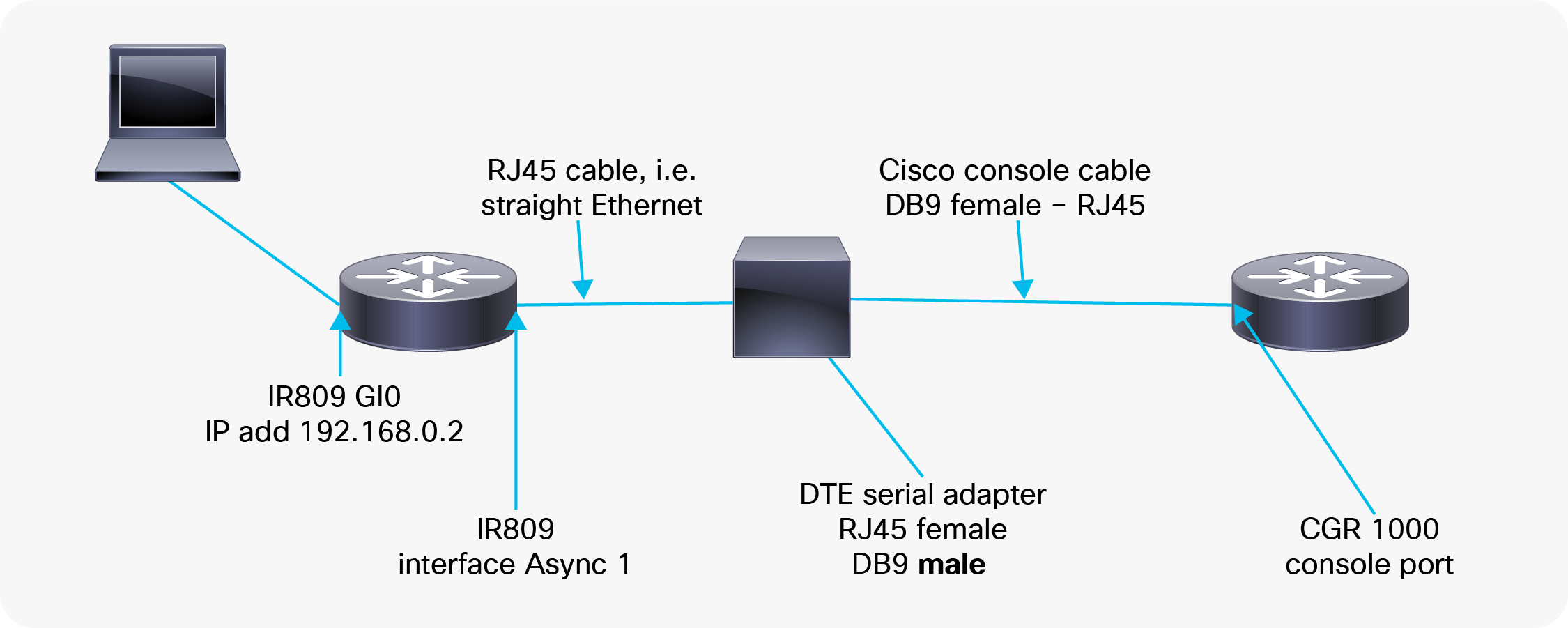
Reverse Telnet is a specialized application of Telnet, in which the server side of the connection reads and writes data to a computer terminal line (RS-232 serial port), rather than providing a command shell to the host device. Cisco routers enable this feature using the serial relay line. Through the use of reverse Telnet, IP-networked users can use Telnet to access serially connected devices. The configuration example shown in Figure 11 uses the Cisco 809 Industrial ISR (IR809) to reverse Telnet into a Cisco 1000 Series Connected Grid Router (CGR 1000) serial port:
Example of a reverse Telnet configuration
2.2.1. Configure the serial port
config terminal
interface Async 1
encapsulation relay-line
2.2.2. Configure the line interface
To find out what “line” the router uses for the serial port, use the “show controllers async 1” command to display the associated line:
IR809-1#sh controllers async 0
Base Address is 0x600
Line: 1 Interface: Async0
IR809-1#sh controllers async 1
Base Address is 0x3F8
Line: 2 Interface: Async1
The snippet below provides the configuration on the line. Please ensure that the databits, parity, and speed match the configuration on the device connected to the serial port.
line 1 2
transport input all
transport output none
exec-timeout 15 0
databits 8
parity none
speed 9600
exit
2.2.3. Use reverse Telnet
To reverse Telnet into the serial port, use the router’s IP address along with port number 2000 plus the line number.
Using the router’s IP address of 192.168.0.2 and port number 2002, this command would be as follows:
telnet 192.168.0.2 2002
Trying 192.168.0.2...
Connected to 192.168.0.2.
Escape character is ‘^]’.
User Access Verification
Username: cisco
Password:
Cgr1000#
2.2.4. Close the session
To close the session, press Ctrl+Shift+6 and then press the letter X. This will close out the session.
To do this outside of config mode (press Ctrl-Z to get out of config mode), enter the command “clear line xxx,” where “xxx” is the line number. It will ask for confirmation. Just press the Enter key.
2.3. Cisco IOx access
Serial relay line allows serial ports to pass traffic directly to the guest OS serial ports. The serial port can also be accessed from Cisco IOx applications running on the gateways. The following document provides information on accessing the serial port from IOx applications:
Accessing Serial Interface on IR829 through GOS
2.4. Protocol translation
Many Cisco IoT routers, such as the 809, 829, 1101 Industrial ISRs, and the 1000 Series CGRs, support translation between the serial and IP SCADA protocols below as a Cisco IOS® function:
● IEC 60870-5-101 to IEC 60870-5-104
● DNP3 to DNP3/IP
The following documents provide step-by-step instructions for configuring protocol translation on Cisco routers:
Cisco IR1101 Integrated Services Router Software Configuration Guide
Cisco IR807 Industrial Integrated Services Router Software Configuration Guide
Additionally, many partner IOx applications, such as Virtual RTU from Eximprod, perform SCADA protocol translations across multiple platforms as an IOx application, offering support for a larger set of protocols, such as Modbus, etc. as well as inter-protocol translation such as Modbus to DNP3-IP, etc. Setup of the serial line must be done as described for IOx. Information about these applications can be found in the Cisco IoT DevCenter
Information on Eximprod can be found here
2.5. CANBUS: Connecting OBD II converters to IoT gateways
Cisco IoT routers such as the 829 Industrial ISR can easily be connected to vehicle OBD II ports through a serial interface. Here are the items required:
● Bidirectional communication with the converter
● Decoding of CAN message (such as SAE J1939)
● Data collection, filtering/processing, storage, and forwarding
The serial interfaces on IoT routers can be configured as explained earlier in the document.
Here is an example of a third-party adapter from Advantech
3. Troubleshooting, tips, and tricks
3.1. Async interface troubleshooting
3.1.1. Port type
The first thing that needs to be considered when connecting a device to the serial port on a Cisco router is the port type. Does the device have a DTE or DCE port? For this, it is essential to find out the “idle state” properties of the serial interface pins. Using the data in Table 5 on the next page, you can determine whether your device port is DCE or DTE. For this, it is recommended that you use a serial breakout box or a digital voltmeter, as shown in Figures 12 and 13 below.

Serial breakout box

Serial breakout box
Table 5. Asynchronous operation
| Lead |
TXD |
RXD |
RTS |
CTS |
DSR |
DCD |
DTR |
| DB25 pin |
2 |
3 |
4 |
5 |
6 |
8 |
20 |
| DB9 pin |
3 |
2 |
7 |
8 |
6 |
1 |
4 |
| DTE idle state |
Low |
– |
High |
– |
– |
– |
High |
| DCE idle state |
– |
Low |
– |
High |
High |
High |
– |
For the purposes of this document, high and low signals are defined as follows:
● Low = Mark = Off = Binary 1 = -5VDc to -15VDC
● High = Space = On = Binary 0 = +5VDC to +15VDC
Many vendors implement these differently, but in most cases, there will be an idle mark on the Transmit Data (TXD) pin of the device. This is the most reliable method to determine if it is a DTE or DCE device.
3.1.2. Cabling
Once you determine the device’s termination type, you can select the correct cabling option from Table 3.
3.1.3. Signal requirements
Once the correct cable is established, you need to find out if the device requires any specific high signals to establish connectivity. This information is generally provided in the device documentation or is determined by testing. Below are some examples:
Example 1
The device is a DTE device but requires that the connected DCE device present a high on CTS, DSR, and DCD before it will become active.
If all three signals are high from the router DCE serial port, connecting these leads directly to the respective router pins should work.
Example 2
The device is a DCE device but requires that the connected DTE device present a high on Request to Send (RTS) and DTR before it will become active.
If RTS and DTR are high from the DTE serial port with a DTE cable, connecting these leads directly to the respective router pins should work.
3.1.4. Flow control
If hardware flow control is desired, this can be configured on the desired line in either direction. Using this feature requires that RTS and CTS be connected and functioning on both ends of the cable path.
The following is a sample configuration for the hardware flow control:
conf t
line <line #>
flowcontrol hardware in
flowcontrol hardware out
Software flow control is also an option if desired and can be used as long as TXD, Receive Data (RXD), and Signal Ground are connected.
The “sh interface” command can be used to find out the relevant control lead states.
IR1101-1#sh int async 0/2/0
…
DSR=down DTR=up RTS=up CTS=down
The example above shows a device connected, which is causing the DTR and RTS signals to go high.
3.2. Troubleshooting RS-485 issues
In scenarios where there is an impedance mismatch between the two sides of an RS-485 or RS-422 connection, an impedance termination might be required.
Here are a few helpful links that discuss when you need termination resistors and why they are required:
https://www.belden.com/products/industrial/cable/bus-cable/rs485
https://www.belden.com/blog/industrial-ethernet/rs-485-cable-critical-to-system-operation
3.3. Accessing CLI on Cisco Kinetic GMM
For devices managed by the Cisco Kinetic™ Gateway Management Module (GMM), user CLI access is by default not enabled. The following document provides necessary instructions for enabling user CLI access
Once console access has been claimed and operational, a user can gain console access by adding the command via the Advanced Template
3.4. Disabling authentication for reverse Telnet scenarios
It is generally recommended that you secure line interfaces through secure authentication. For specific scenarios, such as lab testing, you can temporarily disable authentication on the “line,” using the following instructions:
aaa authentication login NOAUTH none
line <line #>
login authentication NOAUTH
3.5. Providing access to serial interface for both reverse Telnet and IOx applications
The serial port on an IoT router can be accessed by only one device at a time. For scenarios in which access is required for different use cases. such as reverse Telnet and access from IOx applications, use the configuration below:
● To provide serial port access to IOx applications, use:
relay line 1 1/5
This is platform specific; please refer to the following site for guidance on specific platforms
● To provide serial port access to a remote application (through reverse Telnet), use:
no relay line 1 1/5