PDF(519.2 KB) View with Adobe Reader on a variety of devices
Updated:April 12, 2017
Bias-Free Language
The documentation set for this product strives to use bias-free language. For the purposes of this documentation set, bias-free is defined as language that does not imply discrimination based on age, disability, gender, racial identity, ethnic identity, sexual orientation, socioeconomic status, and intersectionality. Exceptions may be present in the documentation due to language that is hardcoded in the user interfaces of the product software, language used based on RFP documentation, or language that is used by a referenced third-party product. Learn more about how Cisco is using Inclusive Language.
This guide provides configuration information for the Raw Socket Transport feature on the Cisco 2010 Connected Grid Router (CGR 2010) as summarized in the Feature History section.
Use this document in conjunction with the CGR 2010 software configuration documentation as listed in the Related Documents section.
Raw Socket Transport
Raw Socket Transport transports streams of characters from one serial interface to another over an IP network for utility applications.
Raw Socket is a method for transporting serial data through an IP network. The feature can be used to transport Supervisory Control and Data Acquisition (SCADA) data from Remote Terminal Units (RTUs). This method is an alternative to the Block Serial Tunnel (BSTUN) protocol.
Raw Socket Transport supports TCP or UDP as the transport protocol. An interface can be configured to use either protocol but not both at the same time. TCP transport is suitable for applications such as control applications that require acknowledged and sequenced delivery of data. For latency-sensitive applications such as line SEL relays, UDP transport provides faster transport of serial data than TCP.
In either transport mode, Raw Socket Transport supports up to 32 sessions per interface (a total of 32 x 32 sessions per CGR 2010).
Raw Socket Transport supports the following for each asynchronous serial interface:
TCP as the transport protocol, with built-in auto TCP connection retry mechanism.
Up to 32 TCP sessions per interface.
Interface configuration as a server, client, or a combination of both.
One server per interface, but multiple clients.
VRF-awareness, which enables the router to send Raw Socket Transport traffic to a server host connected through a Virtual Private Network (VPN) Virtual Routing and Forwarding (VRF) interface.
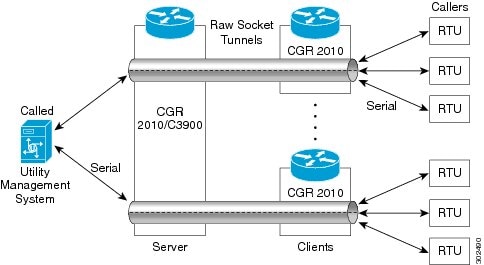
TCP Raw Socket transport uses a client-server model. At most one server and multiple clients can be configured on a single asynchronous serial line. In client mode, the CGR 2010 can initiate up to 32 TCP sessions to Raw Socket servers, which can be other CGR 2010 routers or third-party devices.
Figure 1 shows a sample Raw Socket TCP configuration. In this example, serial data is transferred between RTUs and a utility management system across an IP network that includes several CGR 2010 routers. One CGR 2010 router acts as a Raw Socket server, listening for TCP connection requests from the other CGR 2010 routers, which are configured as Raw Socket clients.
A Raw Socket client receives streams of serial data from the RTUs and accumulates this data in its buffer, then places the data into packets, based on user-specified packetization criteria. The Raw Socket client initiates a TCP connection with the Raw Socket server and sends the packetized data across the IP network to the Raw Socket server, which retrieves the serial data from the packets and sends it to the serial interface, and on to the utility management system.
Figure 1 Raw Socket TCP Transport
Note When you configure the serial link interface on the router as a server, the interface’s peer is the serial link interface on the client router and vice versa.
UDP Transport
UDP transport uses a peer-to-peer model. Multiple UDP connections can be configured on an asynchronous serial line.
Figure 2 shows a sample Raw Socket UDP configuration. In this example, serial data is transferred between RTUs and a utility management system across an IP network that includes two CGR 2010 routers that are configured as Raw Socket UDP peers.
In this example, the Raw Socket UDP peer receives streams of serial data from the RTUs and accumulates this data in its buffer, then places the data into packets, based on user-specified packetization criteria. The Raw Socket UDP peer sends the packetized data across the IP network to the Raw Socket peer at the other end, which retrieves the serial data from the packets and sends it to the serial interface, and on to the utility management system.
Figure 2 Raw Socket UDP Transport
Serial Protocols
The CGR 2010 supports the following serial protocols for Raw Socket Transport:
Asynchronous communication protocol—This is the default. When you use the default protocol, you can select processing options as described in the next section.
Control Data Corporation Type 1 (CDC1) protocol—CDC1 is a bit-oriented SCADA protocol that is used for communication between control stations and RTUs or substations. When you select the CDC1 protocol option, the CGR 2010 packetizes the serial data but does not perform processing before transmitting the data using TCP or UDP.
When the default serial protocol, Asynchronous Communication Protocol, is used, the streams of serial data received by a Raw Socket peer can be packetized based on the following criteria:
Packet length –You can specify a packet length that triggers the CGR 2010 to transmit the serial data to the peer. Once the CGR 2010 collects this much data in its buffer, it packetizes the accumulated data and forwards it to the Raw Socket peer.
Packet-timer value –The packet timer specifies the amount of time the CGR 2010 waits to receive the next character in a stream. If a character is not received by the time the packet timer expires, the data the CGR 2010 has accumulated in its buffer is packetized and forwarded to the Raw Socket peer.
Special character –You can specify a character that will trigger the CGR 2010 to packetize the data accumulated in its buffer and send it to the Raw Socket peer. When the special character (for example, a CR/LF) is received, the CGR 2010 packetizes the accumulated data and sends it to the Raw Socket peer.
In addition to the packetizing options, you can also select best-effort mode for faster processing. This mode trades reliability for speed. If the buffer is full, the CGR 2010 drops the older packets.
The VRF-aware Raw Socket Transport feature enables you to isolate Raw Socket traffic using a VRF for efficient management and control of serial data. After configuring a VRF, you can associate the serial interface configured for Raw Socket Transport with the VRF. See the “Raw Socket VRF” section for a configuration example.
Prerequisites
Determine how you want Raw Socket traffic transported in your network, including the network devices and interfaces to use, how the router packetizes the serial data, and whether to use VRF.
Guidelines and Limitations
Typically, UDP traffic is blocked by firewalls in the network. If the network has such firewalls, make sure to configure pinholes to allow the raw socket UDP traffic.
Enabling Raw Socket Transport on the Serial Interface
To enable Raw Socket Transport on the CGR 2010 router, you must first enable an asynchronous serial port and enable Raw Socket TCP or UDP encapsulation for that port.
BEFORE YOU BEGIN
Determine availability of the serial port on the CGR 2010.
DETAILED STEPS
Command
Purpose
Step 1
configure terminal
Enters global configuration mode.
Step 2
interface serial0 / slot / port
Enters the interface command mode for the serial slot/port.
Step 3
physical-layer async
Places the interface in asynchronous mode.
Step 4
no ip address
Disables IP processing on the interface.
Step 5
encapsulation raw-tcp
or
encapsulation raw-udp
Enables Raw Socket TCP encapsulation or UDP encapsulation for the serial port.
EXAMPLE
This example shows how to enable serial port 0/0/0 and how to enable Raw Socket TCP encapsulation on that port.
router# configure terminal
router(config)# interface Serial0/0/0
router(config-if)# physical-layer async
router(config-if)# no ip address
router(config-if)# encapsulation raw-tcp
router(config-if)# exit
This example shows how to enable serial port 0/0/1 and how to enable Raw Socket UDP encapsulation on that port.
router# configure terminal
router(config)# interface Serial0/0/1
router(config-if)# physical-layer async
router(config-if)# no ip address
router(config-if)# encapsulation raw-udp
router(config-if)# exit
Configuring Common Raw Socket Line Options
You can configure options common to all connections on a line. The common options apply to both TCP and UDP.
Enters line command mode for the serial slot/port.
Step 3
raw-socket protocol cdc1
Specifies the CDC1 communication protocol.
Note The other common line options have no effect when CDC1 is used.
Step 4
raw-socket packet-length length
Specifies the packet size that triggers the CGR 2010 to transmit the data to the peer. When the CGR 2010 accumulates this much data in its buffer, it packetizes the data and forwards it to the Raw Socket peer.
length— 2 to 1400 bytes.
By default, the packet-length trigger is disabled.
Step 5
raw-socket packet-timer timeout
Specifies the maximum time in milliseconds the CGR 2010 waits to receive the next character in a stream. If a character is not received by the time the packet-timer expires, the accumulated data is packetized and forwarded to the Raw Socket peer.
timeout —3 to 1000 ms.
The default is 10 ms.
Step 6
raw-socket spec-char ascii_char
Specifies a character that will trigger the CGR 2010 to packetize the data accumulated in its buffer and send it to the Raw Socket peer.
ascii_char— 0 to 255.
By default, the special character trigger is disabled.
Step 7
raw-socket mode best-effort
Enable best-effort mode for the serial line. When this mode is enabled, older packets are dropped from the head of the queue when the queue is full.
By default, best-effort mode is off.
Use the no form of these commands to return to the default values.
EXAMPLE
router# configure terminal
router(config)# line 0/0/0
router(config-line)# raw-socket packet-length 32
router(config-line)# raw-socket packet-timer 500
router(config-line)# raw-socket special-char 3
Configuring Raw Socket TCP
After enabling Raw Socket TCP encapsulation, you configure the TCP server and/or clients.
Enters line command mode for the serial slot/port.
Step 3
raw-socket tcp server port [ ip_address ]
Starts the Raw Socket Transport TCP server for an asynchronous line interface. In Raw Socket server mode, the CGR 2010 listens for incoming connection requests from Raw Socket clients.
port –Port number the server listens on.
ip_address –(Optional) Local IP address on which the server listens for connection requests.
Step 4
raw-socket tcp idle-timeout session_timeout
Sets the Raw Socket Transport TCP session timeout for the asynchronous line interface. If no data is transferred between the client and server over this interval, then the TCP session closes. The client then automatically attempts to reestablish the TCP session with the server.
This timeout setting applies to all Raw Socket Transport TCP sessions under this particular line.
session_timeout –Currently configured session idle timeout in minutes. The default is 5 minutes.
To remove a Raw Socket TCP server, use the no raw-socket tcp server command.
EXAMPLE
This example shows how to configure a Raw Socket TCP server for an asynchronous serial line. The TCP server listens for TCP client connection requests on local port 4000 and local IP address 10.0.0.1. If no data is exchanged between the Raw Socket TCP server and one of the TCP clients for 10 minutes, then the TCP session closes, and the Raw Socket client attempts to reestablish the session with the Raw Socket server.
router# configure terminal
router(config)# line 0/0/0
router(config-line)# raw-socket tcp server 4000 10.0.0.1
Specifies settings for Raw Socket Transport TCP client sessions.
dest_ip_address –Destination IP address of the remote Raw Socket server.
dest_port –Destination port number to use for the TCP connection to the remote server.
local_ip_address –(Optional) Local IP address that the client can also bind to.
local_port –(Optional) Local port number that the client can also bind to.
Step 4
raw-socket tcp idle-timeout session_timeout
Sets the Raw Socket Transport TCP session timeout for the asynchronous line interface. If no data is transferred between the client and server over this interval, then the TCP session is closed. The client then automatically attempts to reestablish the TCP session with the server.
This timeout setting applies to all Raw Socket Transport TCP sessions under this particular line.
session_timeout –Currently configured session idle timeout in minutes. The default is 5 minutes.
Step 5
raw-socket tcp keepalive interval
Sets the Raw Socket Transport TCP session keepalive interval for the asynchronous line interface. The router sends keepalive messages based on the configured interval. You may need to configure this interval, for example, when sending raw TCP traffic over a cellular interface.
interval –Currently configured keepalive interval in seconds. Range is 1-864000 seconds. The default is 1 second.
To remove a Raw Socket TCP client, use the no raw-socket tcp client command.
EXAMPLE
This example shows how to configure a Raw Socket TCP client for an asynchronous serial line. The CGR 2010 (router), serving as a Raw Socket client, initiates TCP sessions with a Raw Socket server and forwards packetized serial data to it. The router collects streams of serial data in its buffer; when it accumulates 827 bytes in its buffer, the router packetizes the data and forwards it to the Raw Socket server. If the router and the Raw Socket server do not exchange any data for 10 minutes, then the TCP session with the Raw Socket server closes, and the router attempts to reestablish the session with the Raw Socket server.
Configuring a Raw Socket UDP Peer-to-Peer Connection
After enabling Raw Socket UDP encapsulation and the common line options, you configure the Raw Socket UDP peer-to-peer connection. The local port on one end of the connection should be the destination port on the other end.
Specifies settings for Raw Socket Transport UDP connections.
dest_ip_address –Destination IP address to use for the UDP connection.
dest_port –Destination port number to use for the UDP connection.
local_port –Local port number for the UDP connection.
local_ip_address –(Optional) Local IP address for the UDP connection.
To remove a Raw Socket UDP connection, use the no raw-socket udp connection command.
EXAMPLE
This example shows how to configure a Raw Socket UDP connection between router A (local IP address 192.168.0.8) and router B (local IP address 192.168.0.2).
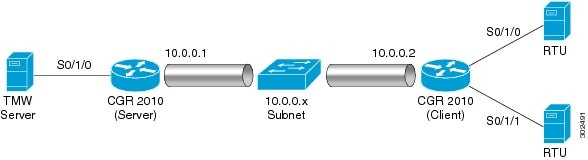
The following example shows a Raw Socket Transport configuration in which a CGR 2010 router acts as the server, and another CGR 2010 router acts as the client.
Figure 3 Raw Socket Transport Configuration Example
The following table displays the configuration of the server and client CGR 2010s highlighted in Figure 3:
CGR 2010 Server Configuration
CGR 2010 Client Configuration
…
interface Serial0/1/0
physical-layer async
no ip address
encapsulation raw-tcp
!
…
line 0/1/0
raw-socket tcp server 5000 10.0.0.1
raw-socket packet-timer 3
raw-socket tcp idle-timeout 5
…
…
interface Serial0/1/0
physical-layer async
no ip address
encapsulation raw-tcp
!
interface Serial0/1/1
physical-layer async
no ip address
encapsulation raw-tcp
!
…
line 0/1/0
raw-socket tcp client 10.0.0.1 5000 10.0.0.2 9000
raw-socket packet-length 32
raw-socket tcp idle-timeout 5
line 0/1/1
raw-socket tcp client 10.0.0.1 5000 10.0.0.2 9001
raw-socket packet-length 32
raw-socket tcp idle-timeout 5
Configuration on the Server Side
This example shows the Raw Socket Transport configuration on the TCP server side.
cgr2010-2067#show run
Building configuration...
Current configuration : 2655 bytes
!
! Last configuration change at 00:03:18 UTC Thu May 31 2013
version 15.2
service timestamps debug datetime msec
service timestamps log datetime msec
no service password-encryption
!
hostname cgr2010-2067
!
boot-start-marker
boot-end-marker
!
!
card type t1 0 3
!
no aaa new-model
no network-clock-participate wic 0
no network-clock-participate wic 3
!
!
!
!
!
!
!
no ip domain lookup
ip cef
no ipv6 cef
multilink bundle-name authenticated
!
!
!
!
license udi pid CGR-2010/K9 sn FTX1532AMCT
!
!
!
!
controller T1 0/3/0
clock source internal
cablelength long 0db
channel-group 0 timeslots 1-24
!
controller T1 0/3/1
cablelength long 0db
!
ip tcp mss 10000
!
!
!
!
interface Loopback0
ip address 3.3.3.3 255.255.255.255
!
interface GigabitEthernet0/0
ip address 10.0.0.97 255.255.255.0
duplex auto
speed auto
!
interface GigabitEthernet0/1
ip address 2.20.56.97 255.255.0.0
duplex auto
speed auto
!
interface Serial0/3/0:0
ip address 100.0.0.1 255.255.255.0
!
interface Serial0/0/0
physical-layer async
no ip address
encapsulation raw-tcp
!
interface Serial0/0/1
physical-layer async
no ip address
encapsulation raw-tcp
!
interface Serial0/0/2
physical-layer async
no ip address
encapsulation raw-tcp
!
interface Serial0/0/3
physical-layer async
no ip address
encapsulation raw-tcp
!
interface Serial0/0/4
physical-layer async
no ip address
encapsulation raw-tcp
!
interface Serial0/0/5
physical-layer async
no ip address
encapsulation raw-tcp
!
interface Serial0/0/6
physical-layer async
no ip address
encapsulation raw-tcp
!
interface Serial0/0/7
physical-layer async
no ip address
encapsulation raw-tcp
!
router ospf 1
router-id 3.3.3.3
network 3.3.3.3 0.0.0.0 area 0
network 100.0.0.0 0.0.0.255 area 0
!
ip forward-protocol nd
!
no ip http server
no ip http secure-server
!
ip route 223.255.254.254 255.255.255.255 2.20.0.1
!
!
!
!
control-plane
!
!
!
line con 0
exec-timeout 0 0
privilege level 15
line aux 0
line 0/0/0
raw-socket tcp server 2012 3.3.3.3
raw-socket tcp idle-timeout 120
line 0/0/1
raw-socket tcp server 2 3.3.3.3
raw-socket tcp idle-timeout 120
line 0/0/2
raw-socket tcp server 3 3.3.3.3
raw-socket tcp idle-timeout 120
line 0/0/3
raw-socket tcp server 4 3.3.3.3
raw-socket tcp idle-timeout 120
line 0/0/4
raw-socket tcp server 5 3.3.3.3
raw-socket tcp idle-timeout 120
line 0/0/5
raw-socket tcp server 6 3.3.3.3
raw-socket tcp idle-timeout 120
line 0/0/6
raw-socket tcp server 7 3.3.3.3
raw-socket tcp idle-timeout 120
line 0/0/7
raw-socket tcp server 8 3.3.3.3
raw-socket tcp idle-timeout 120
line vty 0 4
login
transport input all
!
scheduler allocate 20000 1000
!
end
Configuration on the Client Side
This example shows the Raw Socket Transport configuration on the TCP client side.
cgr2010-2069#show run
Building configuration...
Current configuration : 2726 bytes
!
! Last configuration change at 23:04:49 UTC Fri Jun 1 2013
version 15.2
service timestamps debug datetime msec
service timestamps log datetime msec
no service password-encryption
!
hostname cgr2010-2069
!
boot-start-marker
boot-end-marker
!
!
card type t1 0 3
!
no aaa new-model
!
no network-clock-participate wic 0
no network-clock-participate wic 3
!
!
!
!
!
!
!
no ip domain lookup
ip cef
no ipv6 cef
!
multilink bundle-name authenticated
!
!
!
!
license udi pid CGR-2010/K9 sn FHH1347P010
!
!
!
redundancy
!
!
!
!
!
controller T1 0/3/0
cablelength long 0db
channel-group 0 timeslots 1-24
!
controller T1 0/3/1
cablelength long 0db
!
ip tcp mss 10000
!
!
!
!
!
!
!
!
!
interface Loopback0
ip address 4.4.4.4 255.255.255.255
!
interface GigabitEthernet0/0
ip address 10.0.0.95 255.255.255.0
duplex auto
speed auto
!
interface GigabitEthernet0/1
ip address 2.20.56.95 255.255.0.0
duplex auto
speed auto
!
interface Serial0/3/0:0
ip address 100.0.0.2 255.255.255.0
!
interface Serial0/0/0
physical-layer async
no ip address
encapsulation raw-tcp
!
interface Serial0/0/1
physical-layer async
no ip address
encapsulation raw-tcp
!
interface Serial0/0/2
physical-layer async
no ip address
encapsulation raw-tcp
!
interface Serial0/0/3
physical-layer async
no ip address
encapsulation raw-tcp
!
interface Serial0/0/4
physical-layer async
no ip address
encapsulation raw-tcp
!
interface Serial0/0/5
physical-layer async
no ip address
encapsulation raw-tcp
!
interface Serial0/0/6
physical-layer async
no ip address
encapsulation raw-tcp
!
interface Serial0/0/7
physical-layer async
no ip address
encapsulation raw-tcp
!
!
router ospf 1
router-id 4.4.4.4
network 4.4.4.4 0.0.0.0 area 0
network 100.0.0.0 0.0.0.255 area 0
!
ip forward-protocol nd
!
no ip http server
no ip http secure-server
!
ip route 223.255.254.254 255.255.255.255 2.20.0.1
!
!
!
!
control-plane
!
!
!
line con 0
exec-timeout 0 0
privilege level 15
line aux 0
line 0/0/0 0/0/1
raw-socket tcp client 3.3.3.3 2012
raw-socket packet-timer 500
raw-socket packet-length 827
raw-socket tcp idle-timeout 120
line 0/0/2
raw-socket tcp client 3.3.3.3 3 3
raw-socket packet-timer 500
raw-socket packet-length 827
raw-socket tcp idle-timeout 120
line 0/0/3
raw-socket tcp client 3.3.3.3 4 4
raw-socket tcp idle-timeout 120
line 0/0/4
raw-socket tcp client 3.3.3.3 5 5
raw-socket tcp idle-timeout 120
line 0/0/5
raw-socket tcp client 3.3.3.3 6 6
raw-socket tcp idle-timeout 120
line 0/0/6
raw-socket tcp client 3.3.3.3 7 7
raw-socket tcp idle-timeout 120
line 0/0/7
raw-socket tcp client 3.3.3.3 8 8
raw-socket tcp idle-timeout 120
line vty 0 4
login
transport input all
!
scheduler allocate 20000 1000
!
end
Raw Socket UDP
This example shows the configuration for a Raw Socket UDP connection between two CGR 2010 routers:
From Router1
interface GigabitEthernet0/1
ip address 192.168.0.8 255.255.255.0
duplex auto
speed auto
interface Serial0/0/6
physical-layer async
no ip address
encapsulation raw-udp
line 0/0/6
raw-socket udp connection 192.168.0.2 2 2
raw-socket mode best-effort
From Router2
interface GigabitEthernet0/1
ip address 192.168.0.2 255.255.255.0
load-interval 60
duplex auto
speed auto
no keepalive
interface Serial0/0/6
physical-layer async
no ip address
encapsulation raw-udp
line 0/0/6
raw-socket udp connection 192.168.0.8 2 2
raw-socket mode best-effort
Raw Socket VRF
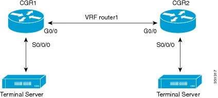
The following example shows a Raw Socket VRF configuration in which two CGR 2010 routers, configured for Raw Socket Transport, connect through a VRF. CGR1 serves as the Raw Socket TCP server, and CGR2 serves as the Raw Socket TCP client.
Figure 4 Raw Socket Transport VRF Configuration Example
Following are the configurations of CGR1 and CGR2 as shown in Figure 4:
CGR1 Configuration
Defining VRF on the router:
vrf definition router1
rd 100:1
route-target export 100:3
route-target import 100:3
!
address-family ipv4
exit-address-family
Applying VRF configuration on the interface:
interface GigabitEthernet0/0
vrf forwarding router1
ip address 100.100.100.2 255.255.255.0
duplex auto
speed auto
Applying raw-tcp on the serial interface:
interface Serial0/0/0
physical-layer async
vrf forwarding router1
no ip address
encapsulation raw-tcp
Applying raw-tcp on the line:
line 0/0/0
raw-socket tcp server 5000 4.4.4.4
CGR2 Configuration
Defining VRF on the router:
vrf definition router1
rd 100:1
route-target export 100:3
route-target import 100:3
!
address-family ipv4
exit-address-family
Applying VRF configuration on the interface:
interface GigabitEthernet0/0
vrf forwarding router1
ip address 100.100.100.1 255.255.255.0
duplex auto
speed auto
Applying raw-tcp on the serial interface:
interface Serial0/0/0
physical-layer async
vrf forwarding router1
no ip address
encapsulation raw-tcp
Applying raw-tcp on line:
line 0/0/0
raw-socket tcp client 4.4.4.4 5000
Related Documents
Cisco 2000 Series Connected Grid Routers Configuration Guides:
To clear Raw Socket Transport statistics for a specific TTY interface or for all asynchronous interfaces, use this command:
clear raw-socket statistics { tty_line_num | all }
Syntax Description
tty_line_num
The asynchronous TTY line number, a value between 3 and 136.
all
All asynchronous TTY line numbers.
Usage Guidelines
After running this command, run the show raw-socket tcp statistics or show raw-socket udp statistics command to verify that the raw statistics have been cleared.
Examples
This is an example of the clear raw-socket statistics command:
To turn Raw Socket Transport driver event debugging on, use this command:
debug raw-socket driver event
Usage Guidelines
Issues you can debug with this command include actions related to:
Packet timer
Packet length
Caution Unless for debugging purposes, we do not recommend turning this command on because it slows down console access and impacts CPU performance, especially in cases of heavy traffic.
To turn this debug command off, run one of these commands:
no debug raw-socket driver event
no debug all
Examples
This example shows the output of the debug raw-socket driver event command:
router# debug raw-socket driver event
*Jun 15 16:12:28.791: rawsocket_get_pak[tty 3]: get pak buffer from pool (0x3168CE24)
*Jun 15 16:12:28.791: rawsocket_get_pak[tty 3]: successfully get pak (0x2A842C70)
*Jun 15 16:12:28.791: rawsocket_tcp_to_async[tty 3]: put pak(0x2A842C70) to queue
*Jun 15 16:12:28.791: rawsocket_async_output[tty 3]: putpkt(0x2A842C70) to physical async line
*Jun 15 16:12:29.083: rawsocket_rx_service[tty 3]: recieved 32 bytes from serial interface
*Jun 15 16:12:29.083: rawsocket_rx_service[tty 3]: Accumulated length(32) met configured pak-length(32)
*Jun 15 16:12:29.083: rawsocket_get_pak[tty 3]: get pak buffer from pool (0x3168CE24)
*Jun 15 16:12:29.083: rawsocket_get_pak[tty 3]: successfully get pak (0x316A0DA8)
*Jun 15 16:12:29.083: rawsocket_async_to_tcp[tty 3]: send pak(0x316A0DA8) to rawsocket
debug raw-socket driver packet
To turn on debugging for issues related to Raw Socket Transport driver packets, use this command:
debug raw-socket driver packet
Usage Guidelines
Issues related to Raw Socket Transport driver packets include packetizing actions based on some or all of the following:
Packet length
Packet timer
Special character
Caution Unless for debugging purposes, we do not recommend turning this command on because it slows down console access and impacts CPU performance, especially in cases of heavy traffic.
To turn this debug command off, run one of these commands:
no debug raw-socket driver packet
no debug all
Examples
This example shows the output of the debug raw-socket driver packet command:
router# debug raw-socket driver packet
*Jun 15 16:09:48.775: rawsocket_async_output[tty 3]: Received 27 byte from socket...
*Jun 15 16:09:49.059: [Async --> Socket] tty(3) Received 32 byte from serial...
debug raw-socket tcp event
To debug issues related to Raw Socket Transport TCP and UDP sessions, use this command to turn TCP and UDP event debugging on:
debug raw-socket tcp event
Usage Guidelines
Issues that you can debug with this command include:
Interface and connection registration
TCP socket establish/release information
Configuration event
Retry information
Caution Unless for debugging purposes, we do not recommend turning this command on because it slows down console access and impacts CPU performance, especially in cases of heavy traffic.
To turn this debug command off, run one of these commands:
no debug raw-socket tcp event
no debug all
Examples
This example shows the output of the debug raw-socket tcp event command:
router# debug raw-socket tcp event
Raw TCP Event Trace debugging is on
router#
router#
router#conf t
Enter configuration commands, one per line. End with CNTL/Z.
*May 17 04:13:10.919: Raw Socket: starting TCP client on interface 0/0/0 tty 3
*May 17 04:13:10.919: Raw Socket: --> server addr: 1.1.1.1 1, local addr: any_ip 1
*May 17 04:13:10.919: Raw Socket: registered config event at 0x30E2874C
*May 17 04:13:11.023: Raw Socket: executing config event at 0x30E2874C retry count (0)
*May 17 04:13:11.023: Raw Socket: start client: interface 0/0/0 tty 3 server addr 1.1.1.1 1
*May 17 04:13:11.023: Raw Socket: connecting to server 1.1.1.1 1
*May 17 04:13:11.023: Raw Socket: created connection socket 0 successfully
*May 17 04:13:11.023: Raw Socket: registered interface 0/0/0 tty 3 to virtual line 0
*May 17 04:13:11.023: Raw Socket: registered client connection 0 on virtual line 0
*May 17 04:13:11.023: Raw Socket: established socket 0 on virtual line 0
router(config-line)#
router(config-line)#
router(config-line)#end
router#no debug raw-socket tcp event
Raw TCP Event Trace debugging is off
debug raw-socket tcp packet
To debug issues related to raw TCP and UDP packets at the socket level, use this command to turn TCP packet debugging on:
debug raw-socket tcp packet
Usage Guidelines
In the output of this command:
Parameter
Description
[From TCP]
Indicates that the frame is from a remote peer.
[To Serial]
Indicates the frame is written to the local asynchronous serial interface.
[From Serial]
Indicates the frame is coming from the local asynchronous serial interface.
[To TCP]
Indicates the frame is sent to the remote peer through the TCP session.
Caution Unless for debugging purposes, we do not recommend turning this command on because it slows down console access and impacts CPU performance, especially in cases of heavy traffic.
To turn this debug command off, run one of these commands:
no debug raw-socket tcp packet
no debug all
Examples
This example shows the output of the debug raw-socket tcp packet command:
router# debug raw-socket tcp packet
Raw TCP Packet Trace debugging is on
router#
*Jun 15 16:04:38.787: [From TCP]<-- received 27 bytes on socket 0 from 3.3.3.3 port 2012
*Jun 15 16:04:39.095: [To TCP]--> dispatched 32 bytes on socket 0 to ip 3.3.3.3 port 2012
encapsulation raw-tcp
To configure an asynchronous interface to run in raw TCP encapsulation, use this command:
encapsulation raw-tcp
Usage Guidelines
To use this command, switch to the Interface Configuration mode (config-if).
Examples
This example shows how to use the encapsulation raw-tcp command:
router# configure terminal
router(config)# interface Serial0/0/0
router(config-if)# encapsulation raw-tcp
encapsulation raw-udp
To configure an asynchronous interface to run in raw UDP encapsulation, use this command:
encapsulation raw-udp
Usage Guidelines
To use this command, switch to the Interface Configuration mode (config-if).
Examples
This example shows how to use the encapsulation raw-udp command:
router#configure terminal
router(config)# interface Serial0/0/0
router(config-if)# encapsulation raw-udp
raw-socket mode best-effort
To enable best-effort mode for the serial line, use this command:
raw-socket mode best-effort
Usage Guidelines
Use best-effort mode for faster transmission of serial data to the Raw Socket peer. Older packets are dropped from the head of the queue when the queue is full.
To use this command, switch to the Line Configuration mode (config-line).
Examples
router# configure terminal
router(config)# line 0/0/6
router(config-line)# raw-socket mode best-effort
router(config-line)# exit
router(config)#
raw-socket packet-length
To set the packet length that the asynchronous serial driver uses to packetize the serial bytes into TCP or UDP frames, use this command:
raw-socket packet-length length
Syntax Description
length
Packet length in bytes (2–1400).
Usage Guidelines
To use this command, switch to the Line Configuration mode (config-line).
Examples
This example shows how to use the raw-socket packet-length command:
router# configure terminal
router# line 0/0/0
router(config-line)# raw-socket packet-length 827
raw-socket packet-timer
To set the packet timer that the asynchronous serial driver uses when packetizing serial bytes into TCP or UDP frames, use this command:
raw-socket packet-timer packet_timer
Syntax Description
packet_timer
The timer value in ms to trigger packetization.
Usage Guidelines
By default, the serial interface packetizes the serial received bytes in its buffer every 10 ms. However, you can change this value using this command. After creating the packet, the interface sends the packet to the peer serial interface on the server side through the Raw Socket Transport tunnel.
On the utility RTU server side, you can set this value to 3 ms to flush polling requests out as soon as possible. The shorter the timer, the sooner the polling data is sent to the RTU client.
To use this command, switch to the Line Configuration mode (config-line).
Examples
This example shows how to use the raw-socket packet-timer command:
router# configure terminal
router(config)#line 0/0/0
router(config-line)# raw-socket packet-timer 1000
raw-socket protocol cdc1
To select the Control Data Corporation Type 1 (CDC1) communication protocol for Raw Socket Transport, use this command:
raw-socket protocol cdc1
Usage Guidelines
When you select the CDC1 protocol, the CGR 2010 packetizes and transports the serial data using TCP or UDP but does not perform processing of the data.
To use this command, switch to the Line Configuration mode (config-line).
The following line option commands have no effect when you use CDC1:
raw-socket packet-length
raw-socket packet-timer
raw-socket spec-char
raw-socket mode best-effort
Examples
This example shows how to use the raw-socket protocol cdc1 command:
router# configure terminal
router(config)# line 0/0/0
router(config-line)# raw-socket protocol cdc1
raw-socket special-char
To set the special character that triggers the packetization of incoming bytes, use this command:
raw-socket special-char special_character
Syntax Description
special_character
The ASCII character (0–255).
Usage Guidelines
When the serial interface detects this special character, the interface packetizes the received bytes into a TCP or UDP frame and sends it to the peer through the Raw Socket Transport tunnel.
To use this command, switch to the Line Configuration mode (config-line).
Examples
This example shows how to use the raw-socket special-char command:
router# configure terminal
router(config)# line 0/0/0
router(config-line)# raw-socket special-char 13
raw-socket tcp client
To initiate a Raw Socket Transport TCP client session, use this command:
To set the Raw Socket Transport TCP session timeout for an asynchronous line interface, use this command:
raw-socket tcp idle-timeout session_timeout
Syntax Description
session_timeout
Currently configured session idle timeout in minutes.
Usage Guidelines
This timeout setting applies to all Raw Socket Transport TCP sessions under this particular asynchronous line. By default, the session idle timeout is 5 minutes.
To use this command, switch to the Line Configuration mode (config-line).
Examples
This example shows how to use the raw-socket tcp idle-timeout command:
0x2AE56C7C 0/2/0 start server ------ 5008 ------- ----- 0 TCP
show raw-socket tcp sessions
To display Raw Socket Transport TCP session details, use this command:
show raw-socket tcp sessions
Usage Guidelines
The returned raw TCP session details include this information
Parameter
Description
Interface
Asynchronous serial interface (and its TTY number) associated with this TCP session.
tty
vrf_name
Name of the VRF associated with this TCP session.
socket
TCP socket number.
mode
The mode:
client—Indicates that this interface is the caller.
server—Indicates that this interface is being called.
local_ip_addr
Local IP address.
local_port
Local port number.
dest_ip_addr
Destination IP address.
dest_port
Destination port number.
up_time
Session up time.
idle_time
Session idle time.
timeout
Currently configured session idle timeout.
After the session idle time reaches the specified idle timeout, the session is removed. The client reconnects to the server based on the retry mechanism.
Examples
This example shows the output of the show raw-socket tcp sessions command:
To display Raw Socket Transport UDP session details, use this command:
show raw-socket udp sessions
Usage Guidelines
The returned raw UDP session details include this information:
Parameter
Description
Interface
Asynchronous serial interface (and its TTY number) associated with this UDP session.
tty
vrf_name
Name of the VRF associated with this UDP session.
socket
UDP socket number.
mode
The mode is always client for UDP sessions.
local_ip_addr
Local IP address.
local_port
Local port number.
dest_ip_addr
Destination IP address.
dest_port
Destination port number.
up_time
Session up time.
idle_time
Session idle time.
timeout
Currently configured session idle timeout.
After the session idle time reaches the specified idle timeout, the session is removed. The client reconnects to the server based on the retry mechanism.
Examples
This example shows the output of the show raw-socket udp sessions command:
Obtaining Documentation and Submitting a Service Request
For information on obtaining documentation, using the Cisco Bug Search Tool (BST), submitting a service request, and gathering additional information, see What’s New in Cisco Product Documentation.
Cisco and the Cisco logo are trademarks or registered trademarks of Cisco and/or its affiliates in the U.S. and other countries. To view a list of Cisco trademarks, go to this URL: www.cisco.com/go/trademarks. Third-party trademarks mentioned are the property of their respective owners. The use of the word partner does not imply a partnership relationship between Cisco and any other company. (1110R)
No combinations are authorized or intended under this document.
Any Internet Protocol (IP) addresses and phone numbers used in this document are not intended to be actual addresses and phone numbers. Any examples, command display output, network topology diagrams, and other figures included in the document are shown for illustrative purposes only. Any use of actual IP addresses or phone numbers in illustrative content is unintentional and coincidental.


 Feedback