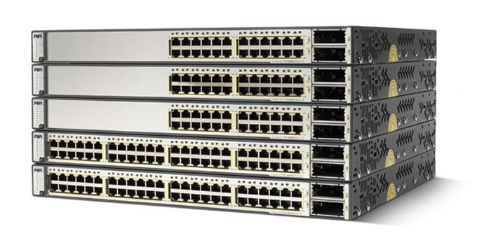
Q. What are the Cisco® Catalyst® 3560-E Series Switches?
A. Cisco® Catalyst® 3560-E Series is an enterprise-class line of standalone access and aggregation switches that facilitate the deployment of secure converged applications while maximizing investment protection for evolving network and application requirements. Combining 10/100/1000 and Power over Ethernet (PoE) configurations with 10 Gigabit Ethernet uplinks, the Cisco Catalyst 3560-E Series access switches enhance worker productivity by enabling applications such as IP telephony, wireless, and video. Cisco Catalyst 3560-E Series aggregation switches deliver secure non-stop unified network services and versatile connectivity in a one rack-unit (1-RU) form factor for space and power constrained environments, enabling businesses to reduce total cost of ownership while maximizing investment protection.
Cisco Catalyst 3560-E Series Primary Features
Q. What are the primary features of the Cisco Catalyst 3560-E Series Switches?
A. The primary features are:
• Cisco TwinGig converter module for migrating links from Gigabit Ethernet to 10 Gigabit Ethernet
• PoE configurations with 15.4W of PoE on all 48 ports
• Industry first portfolio to scale beyond 15.4W per port delivering maximum solution simplicity for 802.11n access point deployments
• Access switch models have modular fan and power supply with externally available backup
• Dual redundant power supplies and fans for Cisco Catalyst 3560E-12D and Cisco Catalyst 3560E-12SD aggregation switches for nonstop operation
• Multicast routing, IPv6 routing, and access control list (ACL) in hardware
• Out-of-band Ethernet management port along with RS-232 console port
Q. What software feature sets do the Cisco Catalyst 3560-E Series Switches support?
A. The Cisco Catalyst 3560-E Series Switches come with a universal image. Customers can activate the IP Base, IP Services, or Advanced IP Services feature set within that universal image through software activation. Software activation authorizes and activates the Cisco IOS® Software feature set. A special file contained in the switch, called a license file, is examined by Cisco IOS Software when the switch is powered on. Based on the license's type, Cisco IOS Software activates the appropriate feature set.
The IP Base feature set enables Layer 2 forwarding, high-availability, quality of service (QoS), and security features along with basic Layer 3 routing, including Enhanced Interior Gateway Routing Protocol (EIGRP) stub mode.
The IP Services feature set enables a richer set of enterprise-class features, including:
• Dynamic routing protocols: Open Shortest Path First (OSPF), EIGRP, and Border Gateway Protocol Version 4 (BGPv4)
• Policy-based routing (PBR): Allows superior control by enabling flow redirection regardless of the routing protocol configured
• Protocol-Independent Multicast (PIM): For IP multicast routing within a network that enables the network to receive the multicast feed requested and for switches not participating in the multicast to be pruned support for PIM sparse mode (PIM-SM), PIM dense mode (PIM-DM), and PIM sparse-dense mode
• Distance Vector Multicast Routing Protocol (DVMRP): Tunneling for interconnecting two multicast-enabled networks across nonmulticast networks
• Private VLAN (PVLAN): Provides the ability to restrict communications between hosts at Layer 2 through the use of primary and secondary VLANs
The Advanced IP Services feature set includes all of the above and full IPv6 routing in hardware.
Q. Can I enable static IP routing using the IP Base feature set?
A. Yes, RIP and static routing are supported on the IP Base feature set. Dynamic IP routing protocols (OSPF, BGPv4, EIGRP) are available only on the IP Services feature set.
Q. What Small Form-Factor Pluggable (SFP) modules are supported on Cisco Catalyst 3560-E Series Switches?
A. Cisco Catalyst 3560-E Series Switches support the following SFPs:
• 1000BASE-LX/LH (GLC-LH-SM=)
• 1000BASE-SX (GLC-SX-SM=)
• 1000BASE-ZX (GLC-ZX-SM=)
• 1000BASE-T (GLC-T=)
• 1000BASE-BX 1490nm (GLC-BX-D=) (12.2(25)SEB and later)
• 1000BASE-BX 1310nm (GLC-BX-U=) (12.2(25)SEB and later)
• CWDM (supported after Cisco IOS Software Release 12.1(14) EA):
– CWDM-SFP-1470
– CWDM-SFP-1490
– CWDM-SFP-1510
– CWDM-SFP-1530
– CWDM-SFP-1550
– CWDM-SFP-1570
– CWDM-SFP-1590
– CWDM-SFP-1610
• 100BASE FX (Cisco IOS Software Release 12.2(20)SE and later)
Q. What X2 modules are supported on Cisco Catalyst 3560-E Series Switches?
A. Cisco Catalyst 3560-E Series Switches support the following X2 modules:
• 10GBASE-SR
• 10GBASE-LR
• 10GBASE-ER
• 10GBASE-LRM
• 10GBASE-LX4
• 10GBASE-CX4
Switch Architecture
Q. What are the notable differences/features between the Cisco Catalyst 3560-E and the Cisco Catalyst 3560?
A. The differences are as follows:
• Cisco Catalyst 3560-E access switches provide a true line-rate (nonblocking) Gigabit Ethernet to the desktop solution with two line-rate 10 Gigabit Ethernet uplinks. The Cisco Catalyst 3560-E also offers aggregation switches - the Cisco Catalyst 3560E-12D, a 12-port 10 Gigabit Ethernet switch, and the Cisco Catalyst 3560E-12SD, a 12-port SFP Gigabit Ethernent switch with 2 10 Gigabit Ethernet uplink ports.
• The Cisco Catalyst 3560-E access switches have a backplane switching application-specific integrated circuit (ASIC), which also makes forwarding decisions, to help the switches perform wire-rate local switching.
• The Cisco Catalyst 3560-E supports a dynamic pluggable module that converts a 10 Gigabit Ethernet slot into a slot that can fit two Gigabit Ethernet ports. This allows for easy migration for customers moving from Gigabit Ethernet links to 10 Gigabit Ethernet links.
• All the Cisco Catalyst 3560-E supports hot-swappable power supplies. In addition, the Cisco Catalyst 3560E-12D and Cisco Catalyst 3560E-12SD aggregation switches offer dual hot-swappable power supplies.
• The Cisco Catalyst 3560-E switches have modular fans. The Cisco Catalyst 3560E-12D and the Cisco Catalyst 3560E-12SD aggregation switches offer four and two redundant field-replaceable fans, respectively.
• The Cisco Catalyst 3560-E supports jumbo frame routing and increases the frame size to 9216 bytes.
• The Cisco Catalyst 3560-E supports uncompressed IPv6 address tables. This allows the software to program the full IPv6 address in the hardware. In addition, equal cost routing for IPv6 uses the uncompressed IPv6 address.
• The Cisco Catalyst 3560-E supports destination stripping of unicast packets.
Q. How many 10 Gigabit Ethernet ports are supported?
A. Two line-rate 10 Gigabit Ethernet ports are supported in Cisco Catalyst 3560-E access switch and the Cisco Catalyst 3560E-12SD aggregation switch. The Cisco Catalyst 3560E-12D aggregation switch supports twelve 10 Gigabit Ethernet ports. These are 2:1 oversubscribed in the worst-case scenario.
Q. Are TwinGig modules included with every Cisco Catalyst 3560-E switch?
A. Users can opt to have up to two TwinGig modules included with the access switch models and the Cisco Catalyst 3560E-12SD aggregation switch. TwinGig modules are not included with the Cisco Catalyst 3560E-12D aggregation switch. They may be ordered as spares.
Q. How does the Cisco Catalyst 3560-E prevent counterfeiting?
A. The switch hardware enables Cisco IOS Software to detect counterfeit products. If Cisco IOS Software detects such products, it warns the customer.
Q. Is jumbo frame routing supported on the Cisco Catalyst 3560-E?
A. Yes, jumbo frame routing is supported.
Q. What types of packets are not hardware-forwarded?
A. The Cisco Catalyst 3560-E Series Switches will completely hardware-forward only IPv4 packets with no options set in Ethernet II encapsulation. This includes bridging, routing, security, and QoS lookups. Packets that do not conform to all three criteria will be forwarded using a combination of hardware or software forwarding. IPv6 is also supported in hardware.
Q. What is onboard failure logging (OBFL)?
A. OBFL provides a mechanism for applications to store critical data in nonvolatile memory in hardware, which can be used by the Cisco Technical Assistance Center (TAC) for troubleshooting and fixing hardware issues. The OBFL data will be recorded on the flash as a separate file system.
Q. What are the management port and its functionality?
A. An out-of-band Ethernet management port is supported in addition to the console port. This port works like a normal Ethernet port except that there is not a data forwarding path.
Q. How many Switch Port Analyzer/Remote Switch Port Analyzer (SPAN/RSPAN) sessions does the Cisco Catalyst 3560-E support?
A. Two sessions are supported on all the Cisco Catalyst 3560-E access switches and the Cisco Catalyst 3560E-12SD aggregation switch. The Cisco Catalyst 3560E-12D aggregation switch supports one SPAN source session.
Q. How many destination ports are supported per SPAN session?
A. Up to 64 are supported.
Q. How should the 10 Gigabit Ethernet uplinks be aggregated?
A. Cisco offers a range of 10 Gigabit Ethernet aggregation solutions. The Cisco Catalyst 6500 and Cisco Catalyst 4500 families contain several options for enterprises seeking high-density, high-performance switching solutions.
The Cisco Catalyst 3560E-12D is a low-density 10 Gigabit Ethernet aggregation switch for branch office and midmarket deployments, for space- and power-constrained applications and mixed Gigabit Ethernet and 10 Gigabit Ethernet aggregation.
Q. Do the Cisco Catalyst 3560E-12D and Cisco Catalyst 3560E-12SD offer the high-availability features required of an aggregation switch?
A. The Cisco Catalyst 3560E-12D and the Cisco Catalyst 3560E-12SD offer many high-availability features that make them robust aggregation solutions:
• Dual hot-swappable power supplies
• Redundant field-replaceable fans
• Advanced IP unicast routing protocols such as OSPF, EIGRP, and BGPv4
• Support for all the Cisco Catalyst 3560-E Cisco IOS Software high-availability features such as FlexLinks and Generic Online Diagnostics (GOLD)
QoS
The following section explains how the QoS mechanisms work for the Cisco Catalyst 3560-E. This includes marking, queuing, and ACLs.
Q. Explain the queuing in the Cisco Catalyst 3560-E.
A. In Figure 1, the Cisco Catalyst 3560-E has two ingress queues and four egress queues. Each of the two sets can be configured for one queue to be a priority queue that gets completely drained before the other weighted queues get serviced. Or each set can be configured to have all weighted queues.
Figure 1. Cisco Catalyst 3560-E Ingress and Egress Queues
The Cisco Catalyst 3560-E employs Shaped Round Robin (SRR). SRR is scheduling service for specifying the rate at which packets are dequeued. With SRR there are two modes, shaped and shared. Shaped mode is only available on the egress queues. Shaped egress queues reserve a set of port bandwidth and then send evenly spaced packets as per the reservation. Shared egress queues are also guaranteed a configured share of bandwidth, but do not reserve the bandwidth. That is, in shared mode, if a higher priority queue is empty, instead of the servicer waiting for that reserved bandwidth to expire, the lower priority queue can take the unused bandwidth. Neither shaped SRR nor shared SRR is better than the other. Shared SRR is used to get the maximum efficiency out of a queuing system, because unused time slots can be reused by queues with excess traffic. This is not possible in a standard Weighted Round Robin (WRR). Shaped SRR is used to shape a queue or set a hard limit on how much bandwidth a queue can use. When you use shaped SRR, you can shape queues within a port's overall shaped rate.
In addition to queue shaping, the Cisco Catalyst 3560-E can rate limit physical ports from 1 percent to 99 percent of line rate. Thus you can shape queues within an overall rate-limited port.
Q. What is the difference between WRR and SRR in shared mode?
A. The preceding question introduces the topic of SRR; refer to it before continuing. See Figure 2.
Figure 2. WRR and SRR
In the examples, Q4 has the highest weight, Q3 lower, and so on. Strict priority queuing is turned off.
SRR differs from typical WRR. With WRR queues are serviced based on the weight. Q1 is serviced for weight 1 period of time, Q2 is served for weight 2 period of time, and so forth. The servicing mechanism works by moving from queue to queue and services them for the weighted amount of time. With SRR weights are still followed; however, SRR services Q1, moves to Q2, then Q3 and Q4 in a different way. It does not wait at and service each queue for a weighted amount of time before moving on to the next queue. Instead, SRR makes several rapid passes at the queues; in each pass, each queue might or might not be serviced. For each given pass, the more highly weighted queues are more likely to be serviced than the lower priority queues. Over a given time, the number of packets serviced from each queue is the same for SRR and WRR. However, the ordering is different. With SRR, traffic has a more evenly distributed ordering. With WRR one sees a bunch of packets from Q1 and then a bunch of packets from Q2 and so on. With SRR one sees a weighted interleaving of packets. In Figure 4, for WRR, all packets marked 1 are serviced, then 2, then 3, and so on until 4. In SRR, all A packets are serviced, then B, C, and D. With SRR there will be interleaving (biased by the weights) for smoother traffic flows. SRR is an evolution of WRR that protects against overwhelming buffers with huge bursts of traffic by using a smoother round-robin mechanism.
Q. Does the Cisco Catalyst 3560-E support congestion avoidance?
A. Yes. Weighted tail drop (WTD) can be applied on any or all of the ingress and egress queues. WTD is a congestion-avoidance mechanism for managing the queue lengths and providing drop precedences for different traffic classifications. Configurable thresholds determine when to drop certain types of packets. The thresholds can be based on class-of-service (CoS) or differentiated services code point (DSCP) values As a queue fills up, lower priority packets are dropped first. For example, you can configure WTD to drop CoSs 0 through 5 when the queue is 60 percent full. In addition, multiple thresholds and levels can be set for different CoS and DSCP values, on a per-queue basis.
Q. Does the Cisco Catalyst 3560-E support aggregate policing?
A. The Cisco Catalyst 3560-E supports aggregate policers where several traffic flows can be policed as a group.
Q. How does the Cisco Catalyst 3560-E classify packets?
A. The Cisco Catalyst 3560-E can classify packets based on the following:
• Layer 2: MAC source address, destination address, 802.1p, Ethertype, ingress port number
• Layer 3: IP destination address, IP source address
• Layer 4: port number, IP type of service (ToS)
Q. Does the Cisco Catalyst 3560-E support egress traffic shaping?
A. Yes, traffic shaping is supported on a per-queue basis, giving the customer great flexibility, because traffic can be mapped to the egress queues based on a per-ACL, flow, CoS, DSCP, and so on basis.
Q. Does the Cisco Catalyst 3560-E support the ability to set the trust state of a port for QoS?
A. Yes, the Cisco Catalyst can be configured to trust a port's CoS, DSCP, or IP precedence. This can be performed on a per-VLAN basis. This is important, because you need to be able to trust the value of higher priority voice VLAN traffic.
Q. Does the Cisco Catalyst 3560-E's QoS support the ability to mark packets in both the ingress and egress directions?
A. Yes, the Cisco Catalyst 3560-E can mark CoS and DSCP in both the ingress and egress directions.
Q. Does the Cisco Catalyst 3560-E's QoS support the ability to schedule packets on both ingress and egress, as part of a congestion-avoidance mechanism? Describe the implementation.
A. Yes. This is discussed in the section about ingress and egress QoS.
Q. Is the IP Services license required for Layer 3 QoS?
A. No, both the IP Base feature set and the IP Services feature set can perform Layer 3 QoS.
Q. Is the IP Services feature set required to allow Layer 3 and Layer 4 lookups for QoS and security?
A. No, both the IP Base feature set and the IP Services feature set allow for Layer 3 and Layer 4 lookups for QoS and security.
Q. How granular can the policing be?
A. The committed information rate (CIR) is 8 KB to 1 GB, and the burst rate is 8 KB to 1 MB.
Q. Describe policing as it relates to VLAN policies.
A. Although a policy map can be applied to the VLAN interface, any policing or rate-limiting action can only be performed on a per-port basis: that is, it is impossible to have the policer configured generally to take account of the sum of traffic from a number of physical ports. Each port needs to have a separate policer governing the traffic coming into that port. Each interface must be specified in a second-level policy map by the class map that matches that interface.
Q. Is per-flow policing supported?
A. Yes, per-flow policing is supported.
Q. Is port rate limiting supported?
A. Yes, port rate limiting is supported from 1 percent to 99 percent of the given port's speed.
Q. Is egress policing supported?
A. Egress policing is not supported. However, different packet flows can be mapped into queues. These queues can then be shaped. This will limit the amount of traffic on those flows, similar to that of egress policing.
GOLD
This section discusses Cisco GOLD tools that provide real-time diagnoses for hardware and software issues that might arise on the Cisco Catalyst 3560-E and Cisco Catalyst 3750-E.
Q. What is GOLD?
A. GOLD is a Cisco IOS Software subsystem that was initially developed by and has been adopted by several Cisco platforms. GOLD is an important feature because it allows users to run comprehensive nondisruptive and disruptive tests to be used in diagnosing hardware and software problems.
Q. What tests are included in GOLD?
A. GOLD is a suite of diagnostics tests that address the need for comprehensive troubleshooting tools that can be used by customers or the TAC. The diagnostics are as follows:
• Nondisruptive: Power supply replacement recommendations, error counter reporting.
• Health monitoring: Periodic running of nondisruptive tests while the system is in operation.
• On demand: Tests run interactively with the administrator.
• Scheduled: Tests run at a specific time daily, weekly, or just once. Correct operation is dependent on the time source being configured on the switch, such as by manual user input or Network Time Protocol (NTP).
Q. Do I need to load a special diagnostic image onto the switch to run GOLD?
A. No, GOLD is part of runtime Cisco IOS Software, unlike many competitors' switches.
Q. Do I have to take a switch out of service to run GOLD diagnostics?
A. No, many GOLD diagnostics can be run without taking the switch out of service and without disrupting traffic.
Q. Can GOLD be run on demand and at scheduled intervals?
A. Yes, GOLD diagnostics can be run on demand or scheduled.
Q. Does the on-demand interactive test include disruptive tests, and can the test be aborted?
A. Yes, on-demand tests include disruptive tests. Those tests will require a confirmation from the user to abort the tests.
Q. How many tests can I schedule, and can I run the tests more than once?
A. A user can schedule multiple and unlimited tests. Those tests can be scheduled to run once, daily, or periodically.
Q. Are health monitoring tests disruptive to switch operations?
A. No, the health monitoring tests are run in the background and can be disabled/enabled using the command-line interface (CLI).
Q. How often are health monitoring tests run?
A. An interval for each test can be configured. The frequency ranges are 365 days to 15 seconds, and the granularity is as small as 50 milliseconds.
Q. Where are test results, schedules, and health monitoring configurations stored?
A. All information is stored in flash and in the configuration file. That is, schedule and health monitoring configurations are part of the switch configuration.
FlexLinks
This section discusses the operation and uses for Cisco FlexLinks.
Q. What are FlexLinks?
A. FlexLinks are a feature that provides Layer 2 resiliency, typically run between access and distribution switches. It has faster convergence times over Spanning Tree Protocol/Rapid Spanning Tree Protocol/IEEE 802.1w. FlexLinks are implemented on Cisco Catalyst 3000 Series and Cisco Catalyst 6000 Series Switches. FlexLinks provide subsecond convergence in less than 100 milliseconds (ms). That is, there is less than a 100-ms convergence time from the active link's failure detection to the forwarding of traffic on a backup link. FlexLinks are deployed in pairs: that is, two ports. One port is the active port, and the second is a backup port. Those ports can be either an access port, an EtherChannel® port, or a trunk port.
Q. Do FlexLinks disable Spanning Tree Protocol on the Cisco Catalyst 3560-E?
A. No, FlexLinks only disable Spanning Tree Protocol on the FlexLinks pair. That is, only the uplink ports configured for FlexLinks (active and backup) will have Spanning Tree Protocol disabled. It is recommended that Spanning Tree Protocol not be disabled on all of the remaining ports, to avoid network loops.
Q. Is the backup port blocked just like with Spanning Tree Protocol?
A. Not necessarily. The latest enhancements to FlexLinks allow the backup port to be active for some VLANs. These same VLANs are backed up by the active port, much like Multiple Spanning Tree Protocol. This is called load balancing and allows users to have two active links rather than one active and one backup. While some VLANs use one link as active, other VLANs use that same link as backup.
Q. Is there a load balancing mode in FlexLinks?
A. Yes, there is a VLAN balancing configuration. In a dual-homed configuration, some VLANs will use one link as the active link (link A) and the other as the backup link (link B), while the others will use link B as the active link and link A as the backup.
Q. Can I make a ring topology with FlexLinks?
A. No, FlexLinks are intended for uplinks as an alternative to Spanning Tree Protocol. A ring topology is not supported.
Q. Can I configure FlexLinks over EtherChannel ports, trunks, or access ports?
A. Yes, FlexLinks can be configured on all port types, EtherChannel ports, trunks, and access ports.
Q. Must active and backup ports be of the same port type?
A. No. Port pairings can have an EtherChannel port as the active port and an access port as a backup port and do not have to be of the same speed.
Q. After a failover, is preemption supported in case the high-bandwidth primary link comes back online?
A. Yes, preemption can be configured, but is off by default. Preemption can be configured based on a port's bandwidth. Also, delays can be added in case the primary link is flapping to avoid multiple switchovers from active to backup. Also, preemption can be forced; in this case, the delay timer is ignored.
Q. Do FlexLinks have a tuning mechanism that allows users to avoid link flap?
A. Yes, delays can be added in case the primary link is flapping to avoid multiple switchovers from active to backup.
Q. Do I have to enable MAC move updates (MMU) with FlexLinks?
A. No, but MMU is recommended in order to speed up bidirectional convergence. MMU notifies the switches in the distribution layer about MAC table changes. Note: The Cisco Catalyst 6000 product line does not support MMU, but it is on the roadmap.
Q. Should I turn off Spanning Tree Protocol when FlexLinks is running?
A. No, Spanning Tree Protocol will only be disabled on the FlexLinks pair by default. Spanning Tree Protocol will be used on other ports and the VLAN of the switch.
Security
The following section explains the security features on the Cisco Catalyst 3560-E.
Q. What are the supported violation modes in the port security feature?
A. The interface can be configured for one of the following violation modes:
• Protect: When the number of secure MAC addresses reaches the limit allowed on the port, packets with unknown source addresses are dropped until a sufficient number of secure MAC addresses is removed or the number of maximum allowable addresses is increased. In this mode, the user will not be notified that a security violation has occurred. Note that Cisco does not recommend enabling the protect mode on a trunk port. The protect mode disables learning when any VLAN reaches its maximum limit, even if the port has not reached its maximum limit.
• Restrict: When the number of secure MAC addresses reaches the limit allowed on the port, packets with unknown source addresses are dropped until the user removes a sufficient number of secure MAC addresses or increases the number of maximum allowable addresses. In this mode, the user is notified that a security violation has occurred. A Simple Network Management Protocol (SNMP) trap is sent, a syslog message is logged, and the violation counter increments.
• Shutdown: In this mode, a port security violation causes the interface to immediately become error-disabled and turns off the port LED. It also sends an SNMP trap, logs a syslog message, and increments the violation counter.
Q. What are Dynamic Host Configuration Protocol (DHCP) snooping and DHCP option 82?
A. DHCP snooping allows the switch to "snoop" the switching traffic for DHCP packets. It acts like a firewall between hosts and the DHCP server. It provides DHCP-specific security features such as:
• Verifying the intercepted DHCP messages from untrusted ports
• Performing per-port DHCP message-rate limiting
• Keeping track of DHCP IP address assignment binding between the DHCP server and clients
• Inserting DHCP option 82 into and removing DHCP option 82 from DHCP messages
DHCP option 82 provides an easy way to locate which port a user is attached to, using the client's IP address. This extension to DHCP enables an edge switch to insert information about itself in the DHCP request packet that is destined to the DHCP server.
Q. What do I need to configure, on upstream routed interfaces, if DHCP option 82 is configured on the access switch?
A. If DHCP option 82 information is being inserted, upstream routed interfaces must be configured with a trust relationship to the downstream DHCP snooping switches that add option 82. This is done with the IP DHCP relay information trusted command, in the VLAN interface configuration toward the downstream switch.
Q. What is the DHCP snooping binding table?
A. The DHCP snooping binding table contains the following:
• DHCP option 82 information
• MAC address
• IP address
• Lease time
• Binding type
• VLAN number
• Interface information that corresponds to the local untrusted interfaces of a switch
However, the table does not contain information regarding hosts interconnected with a trusted interface.
Q. What is the maximum number of DHCP snooping binding table entries?
A. Up to 8000 entries are supported.
Q. How can I keep the bindings intact when the switch reloads?
A. To keep the bindings intact when the switch reloads, use the DHCP snooping database agent. The database agent stores the bindings in a file at a configured location. When reloading, the switch reads the binding file to build the DHCP snooping binding database. The switch keeps the file current by updating it when the database changes.
Q. What is the dynamic ARP inspection (DAI) feature?
A. DAI is used to inspect all ARP requests and replies coming from user-facing ports to help ensure they belong to the ARP owner. The ARP owner is the port that has a DHCP binding matching the IP address contained in the ARP reply. ARP packets from DAI trusted ports are not inspected and are bridged to their respective VLANs. The feature is configured on per-VLAN basis.
Q. What is the IP source guard (IPSG) feature?
A. IPSG dynamically creates an ACL based on the contents of the DHCP snooping binding table. This ACL will enforce traffic to be sourced from the IP address issued at the DHCP binding table and prevent any traffic from being forwarded by other spoofed addresses.
Q. Why is DHCP option 82 required to implement IPSG with IP and MAC address verification?
A. IPSG can perform source IP and MAC checking or only source IP address checking. However, IP MAC filtering is achieved by using both port security and DHCP option 82. Enabling port security with switchport port security is required on the interface. In addition, for IP MAC filtering, option 82 is required on the switch and the DHCP server. Option 82 is required since the switch does not perform any MAC address learning for DHCP and ARP packets when IP MAC filtering is configured. This is done to prevent a security hole, since any host can formulate a bogus DHCP and ARP packet. If option 82 is not supported on the DHCP server, IP MAC filtering will still work using static bindings.
Q. Do DAI and DHCP snooping prevent denial-of-service (DoS) attacks?
A. Yes, DAI helps prevent DoS attacks by limiting the number of incoming ARPs per second on an interface. Because this feature performs validation checks in the CPU, the incoming ARPs on every interface with DAI will be rate limited. DAI performance depends on the number of interfaces within a VLAN.
When the rate of incoming ARP packets exceeds the configured limit, the switch places the port in the error-disabled state. The port remains in that state; a human intervention will be required to shut or unshut the interface for normal processing. An "error-disable" recovery can also be configured, so the ports automatically emerge from this state after a specified timeout period.
Q. What are the supported 802.1x enhancements features?
A. The following features are supported:
• 802.1x authentication with VLAN assignment
• 802.1x authentication with per-user ACLs
• 802.1x authentication with guest VLAN
• 802.1x authentication with inaccessible authentication bypass
• 802.1x authentication with voice VLAN ports
• 802.1x authentication with port security
• 802.1x authentication with wake on LAN
• 802.1x authentication with MAC authentication bypass
Q. What is Network Admission Control (NAC)?
A. NAC assesses the state, or posture, of endpoint devices such as desktop computers, laptops, and servers in order to prevent unauthorized or vulnerable hosts from accessing the network. Authentication and posture validation occur when a host requests access to a network. Through Layer 2 or Layer 3 transport, a network access device (NAD) retrieves posture credentials from the host. The amount of network access granted to the host is determined by its identity and/or level of compliance with posture policy rules, which are defined on the access control server (ACS). These posture credentials are typically based on the state of the host operating system and antivirus applications running on the host.
Q. Is 802.1X, per-user ACL, supported in conjunction with NAC?
A. No, it is not supported.
Q. What is MAC authentication bypass (MAB)?
A. MAB is used to authorize an attached host by authorizing it based on its MAC address.
Q. In case of MAB, if a supplicantless PC disconnects from an IP phone, will the switch get notified of this disconnect?
A. No. The phones will send out Extensible Authentication Protocol over LAN-Logoff (EAPOL-Logoff), but only if 802.1x was on the wire to begin with.
Q. Is Cisco Clean Access supported in Cisco Catalyst 3560-E Series Switches?
A. Yes, Cisco Clean Access is supported.
Q. Are reflexive or dynamic ACLs supported in Cisco Catalyst 3560-E Series Switches?
A. No, neither feature is supported.
Q. Are time-based ACLs supported in Cisco Catalyst 3560-E Series Switches?
A. Yes, time-based ACLs are supported.
Q. What is storm control, and is it supported on the Cisco Catalyst 3560-E Series Switches?
A. Storm control prevents traffic on a LAN from being disrupted by a broadcast, multicast, or unicast storm on one of the physical interfaces. Storm control uses one of these methods to measure traffic activity:
• Bandwidth as a percentage of the total available bandwidth of the port that can be used by the broadcast, multicast, or unicast traffic
• Traffic rate in packets per second at which broadcast, multicast, or unicast packets are received
• Traffic rate in bits per second at which broadcast, multicast, or unicast packets are received
Q. Is the private VLAN feature supported?
A. Yes, private VLANs are supported.
PoE
The following section discusses the PoE features in the Cisco Catalyst 3560-E.
Q. Does the Cisco Catalyst 3560-E PoE switch support the IEEE 802.3af standards-based implementation?
A. Yes, the Cisco Catalyst 3560-E PoE switches support both the Cisco prestandard PoE implementation, as well as the IEEE 802.3af PoE implementation.
Q. Do the Cisco Catalyst 3560E-12D and the Cisco Catalyst 3560E-12SD aggregation switches support PoE?
A. No. PoE is only supported by the PoE access models in the Cisco Catalyst 3560-E Series.
Q. What method of disconnect does the Cisco Catalyst 3560-E PoE support?
A. The Cisco Catalyst 3560-E PoE switches support AC disconnect detection for both IEEE802.3af standard compliance and prestandard Cisco powered devices.
Q. What method of detection does the Cisco Catalyst 3560-E PoE support?
A. The Cisco Catalyst 3560-E PoE switches support both Cisco prestandard PoE and standards-based PoE methods of detecting a powered device. Both detection methods are active at the same time, and either one can be used to detect a valid powered device.
Q. Do the Cisco Catalyst 3560-E PoE switches support power classification?
A. Yes, Cisco Catalyst 3560-E switches can optionally detect the powered device power classification signature and budget the appropriate power. This reduces the maximum power that must be budgeted by the switch and provisioned in the wiring closet.
Q. What is the maximum power per port that the Cisco Catalyst 3560-E PoE can supply?
A. The maximum power supplied by the Cisco Catalyst 3560-E PoE is 15.4 watts (W) per port. However, with the 12.2.44 software release, the 3560-E series PoE switches can scale beyond 15.4W per port delivering maximum solution simplicity for 802.11n access point deployments.
Q. Can the Cisco Catalyst 3560-E PoE switch power up the 802.11n access point?
A. Yes, the Cisco Catalyst 3560-E PoE switches with the 12.2.44 software release can scale beyond 15.4W per port to power up the 802.11n access point.
Q. How does power management work on Cisco Catalyst 3560-E PoE switches?
A. The 24-port and 48-port Cisco Catalyst 3560-E switches support a maximum of 15.4W per port of -48VDC power on all ports over standard Category 3 and 5 unshielded twisted-pair (UTP) cable up to 100 meters. The Cisco Catalyst 3560-E PoE switches monitor and track the requests for power and only grant power when it is available. If the connected powered device draws more power, which results in exceeding the system power budget that is available on the switch, then power will be denied to that port, and the powered device will not power up. If power is denied, the switch rechecks the power budget periodically (every 15 seconds) and continues to attempt to grant the request for power. If power is granted, the switch updates the power budget. Additional power management features are described later in this section.
Q. What pair set is used to support DC power in Cisco Catalyst 3560-E PoE switches?
A. Pairs 2 and 3 (pins 1, 2, 3, and 6) of the four pairs in Category 3 and 5 cables are used for both the Ethernet data signals and the DC power at the same time. The powered device must accept either polarity of power from either pair set. This allows both crossover and straight cables to be used. Only straight cables should be used with the prestandard Cisco powered devices.
Q. What is the PoE default configuration on Cisco Catalyst 3560-E PoE switches?
A. All the 10/100 Fast Ethernet ports are by default configured as "auto." This means that powered device discovery is enabled, and powered devices are powered up first come, first served. The 10/100 Fast Ethernet ports can also be configured as "never." This means that the powered device discovery is disabled on those ports.
Q. How do the Cisco Catalyst 3560-E PoE switches behave if the powered device is connected to wall power?
A. If a Cisco Catalyst 3560-E is powering a powered device, and then if the powered device gets connected to an electrical wall outlet, the switch will continue to report that the powered device is powered inline. If a powered device is being wall powered first, which in this case means a wall plug is connected before an Ethernet cable, then if wall power is disconnected, the powered device will reset, and discovery begins.
Q. What kind of safety protection does the Cisco Catalyst 3560-E PoE offer if a port gets an overcurrent condition?
A. Each port on the Cisco Catalyst 3560-E has individual overcurrent and short circuit protection designs. Each port is designed for 350 millamps (mA) and will shut off if current exceeds 400 mA for more than 75 ms. A low-ohm short circuit will be detected in less than 1 ms, and power will be shut off immediately. Each port is designed to recover from an overcurrent or short circuit condition automatically when the fault is removed. Each port is independent, and a fault on one port does not affect other ports.
Q. Is the power consumption CLI command supported on the Cisco Catalyst 3560-E platforms?
A. Yes. By using the power inline consumption wattage configuration command, you can override the default power requirement specified by the IEEE classification and Cisco Discovery Protocol. The difference between what is mandated by the IEEE classification and what is actually needed by the device is reclaimed into the global power budget for use by additional devices. You can then extend the switch power budget and use it more effectively.
Q. What is the bidirectional Cisco Discovery Protocol (Power Negotiation Protocol [PNP]), and is it supported on Cisco Catalyst 3560-E PoE switches?
A. PNP enables high-power powered devices (powered devices that consume more than 7W) to operate in high-power mode on the Cisco Catalyst 3560-E and the Cisco Catalyst 3560 PoE switches. This protocol is supported on the Cisco Catalyst 3560 and the Cisco Catalyst 3560-E PoE switches. PNP is supported currently on the Cisco Unified IP Phone 7970G and is being phased into all high-power powered devices. When the high-power powered devices are connected to the Cisco Catalyst 3560-E and Cisco Catalyst 3560 PoE switches, the powered device boots up in low-power mode and requests to move into high-power mode by incrementing the request ID and sending a list of possible power modes. Upon receiving this request, the switch will select the highest mode possible from the list of power modes. The decision which power mode to select is based on hardware limits, current power available in the global power budget, and user configuration. The switch will set the available power Cisco Discovery Protocol field to the chosen value and respond to the powered device request. If a powered device is denied transition to high-power mode, it will not request again to transition, unless it is unplugged and replugged into the port.
Q. Is automatic medium-dependent interface crossover (auto-MDIX) supported on PoE ports?
A. Yes, auto-MDIX is supported on the Fast Ethernet PoE ports and as well as 10/100/1000 ports. Auto-MDIX operates the same for a PoE port as for a non-PoE port. When auto-MDIX is enabled, and a traditional powered device is connected to the Cisco Catalyst 3560 or Cisco Catalyst 3560-E PoE switches with crossover cable, the powered device is detected and power is granted, followed by an AC disconnect. This behavior happens repeatedly until the cable is changed. Auto-MDIX only works if the port is configured for autospeed and autoduplex.
Q. What are the discovery and disconnect timing restrictions required by IEEE802.3af?
A. The Cisco Catalyst 3560 and Cisco Catalyst 3560-E PoE switches detect the connected powered device within 500 ms. After successful detection, the switch turns on the power within 400 ms. At the time of disconnect, power is removed from the port within 500 ms.
Q. How is PoE delivered over Gigabit Ethernet pairs? How is that different than PoE over Fast Ethernet pairs?
A. The PoE feature is -48VDC power provided over standard Category 3 and 5 unshielded twisted-pair cable up to 100 meters on the Fast Ethernet 10/100 and 10/100/1000 Gigabit Ethernet copper port.
Q. How much power is budgeted for a powered device that does not support IEEE power classification?
A. 15.4W is budgeted.
Q. Can I support 15.4W on all 48 ports?
A. Yes, the total PoE power available on the Cisco Catalyst 3560-E with 48 PoE ports would depend on the installed power supply modules in the switch. With a 1150W power supply, the 48-port switch can support up to 15.4W of power per port.
Q. Is there PoE on the SFP ports that use the 10/100/1000 SFP?