- What’s New in This Chapter
- Types of Conferences
- Cisco Rich Media Conferencing Architecture
- Role of Cisco TelePresence Conductor
- Role of the TelePresence Server
- Role of Cisco TelePresence Management Suite (TMS)
- Conference Bridges for Non-Scheduled Conferences
- Conference Bridges for Scheduled Conferences
- Audio-Only Versus Video Conferencing
- Scheduled Versus Non-Scheduled Conferencing
- Deployment Considerations
- Design Considerations for Audio and Video Conferencing
Cisco Rich Media Conferencing
Revised: January 15, 2015; OL-30952-03
Conferencing is an essential component of any collaboration system, especially when serving remote users and/or a large user base. Cisco Rich Media Conferencing improves on traditional conferencing by offering features such as instant, permanent, and scheduled audio and video conferencing, as well as application sharing.
Conference bridges provide the conferencing function. A conference bridge is a resource that joins multiple participants into a single call (audio or video). It can accept any number of connections for a given conference, up to the maximum number of streams allowed for a single conference on that device. The output stream for a given party is the composite of the streams from all connected parties minus their own input stream.
To provide a satisfactory end-user experience, careful planning and design should be done when deploying Cisco Rich Media Conferencing so that users are enabled with the conferencing functionality they require.
To aid in the Cisco Rich Media Conferencing design, this chapter discusses the following main topics:
This section provides an introduction of the different types of conferences supported throughout the Cisco Rich Media Conferencing Architecture.
This section introduces the main components of Cisco Rich Media Conferencing and describes its advantages as well as the different conferencing mechanisms available through the various components of a collaboration system such as Cisco Unified Communications Manager and Cisco TelePresence Video Communication Server. Supported deployment models, solutions and recommendations are discussed here as well.
This section discusses best practices for designing a resilient Cisco Rich Media Conferencing solution; it also contains guidance for redundancy and load balancing.
This section provides best practices and design information related to capacity limits and scalability for Cisco Rich Media Conferencing.
This section discusses general recommendations and best practices for the Cisco Rich Media Conferencing design.
What’s New in This Chapter
This chapter has been updated with new support and updated designs for Cisco Collaboration System Release 10.6. You should read this entire chapter before deploying Rich Media Conferencing in your Cisco Collaboration System.
Table 11-1 lists the topics that are new in this chapter or that have changed significantly from previous releases of this document.
Types of Conferences
The Cisco Rich Media Conferencing solution supports the following types of conferences:
An instant audio or video conference (also referred to as an ad hoc conference) is an impromptu conference. Instant conferences are not scheduled or arranged prior to the conference. For example, a point-to-point call escalated to a multipoint conference is considered to be an instant conference.
Permanent conferences (also referred to as meet-me, static, or rendezvous conferences) are predefined addresses that allow conferencing without previous scheduling. The conference host shares the address with other users, who can call in to that address at any time.
Permanent conference resources are used on a first-come-first-served basis (non-assured). For a guaranteed conference resource (assured), scheduled conferences should be used. (See Scheduled Conference.)
Cisco Collaboration Meeting Room (CMR)
Cisco CMR Hybrid (formerly, WebEx Enabled TelePresence)
Cisco Personal Multiparty Basic:
- Includes a named host, four-party license for multiparty video and audio with content sharing
- Supports video resolution up to 720p at 30 frames per second (fps) and content resolution up to 720p at 5 fps
- Easily adds participants during a meeting
- Includes a personal conference address for every host
- Enabled by Cisco TelePresence Server and TelePresence Conductor
- Supports single screen endpoints
Personal Multiparty Advanced (in addition to the above capabilities):
- Provides meeting scheduling capability
- Supports an unrestricted number of participants in a meeting (within the limits of the fair use policy)
- Supports video and content resolution up to 1080p at 30 fps
- Supports Microsoft Lync and business-to-business interoperability with Cisco Expressway Rich Media Session (RMS) licenses
- Supports multi-screen endpoints
Cisco Rich Media Conferencing Architecture
The Cisco conferencing architecture enables rich conferencing collaboration capabilities for endpoints registered to Cisco Unified Communications Manager (Unified CM) as well as the ability to integrate business-to-business audio and video systems and legacy H.323 video systems interworked from Cisco Expressway to Unified CM. This architecture provides a rich feature set by relying on a variety of components in the conferencing solution. The following sections present an overview of those components and their roles in the Cisco rich media conferencing solutions.
Role of Cisco TelePresence Conductor
Cisco TelePresence Conductor manages the bridge resources for permanent and instant conferences and, as of Cisco Collaboration System Release (CSR) 10.6, can even manage scheduled conferencing resources. TelePresence Conductor selects which bridge or bridge pools to use to host a specific conference, and it balances the conference load across the bridges in the defined pools. Unified CM is unaware of the individual bridges in the network and communicates only with the TelePresence Conductor.
Using TelePresence Conductor for conferences has several benefits, including:
- Increased efficiency by allowing instant, permanent, and CMR conferences as well as scheduled conferences to use the same TelePresence Servers
- Better user experience through advanced TelePresence Server features such as ActiveControl and dynamic optimization of resources
- Simpler deployment options through provisioned CMRs
- Centralized management of scheduled resources
- Increased scalability of a rich media conferencing solution
In certain cases TelePresence Conductor optimizes TelePresence Server resources dynamically when the Optimize resources setting is enabled in the TelePresence Conductor conference template. This enforces maximum resource usage of a participant based on the maximum receive bandwidth advertised by the resources at conference join. This can reduce the amount of resources conference calls use and allows more concurrent connections to take place. For more information, see the TelePresence Server release notes available at
http://www.cisco.com/c/en/us/support/conferencing/telepresence-server/products-release-notes-list.html
Role of the TelePresence Server
Cisco TelePresence Server is a scalable videoconferencing bridge that offers flexible video, audio, and content-sharing capabilities for multiparty videoconferencing. It allows users to easily create, launch, and join meetings using standards-based video endpoints, mobile devices, Cisco WebEx clients, and third-party video endpoints. It works in conjunction with Cisco TelePresence Conductor to offer flexible, cost-efficient conferencing.
- A consistent user experience across mobile, desktop, or room-based videoconferencing solutions
- Flexible layouts, and views optimized for the capabilities of each device
- Enhanced user experience with features including Cisco TelePresence ActivePresence screen layout, individual participant identifiers, and Cisco ClearPath
- The ability to extend scale and reach to more participants to join meetings by extending meetings to WebEx Meeting Center users
Cisco TelePresence Server is available as a virtualized application compatible with standard Cisco Unified Computing System (UCS) servers, or you can deploy it on dedicated hardware platforms.
Flexible licensing options are offered to enable you to deploy Cisco TelePresence Server capabilities in the way that best suits your needs. You can license Cisco TelePresence Server in conjunction with Cisco TelePresence Conductor on a per-user basis for high-quality small group instant conferencing, with Cisco Personal Multiparty licensing, or on a concurrent call (screen) basis to enable the whole enterprise without restrictions.
Role of Cisco TelePresence Management Suite (TMS)
Cisco TMS provides scheduling, control, and management of Cisco TelePresence conferencing and media services infrastructure and endpoints. Cisco TMS integrates and searches directories and external information sources. It also coordinates with third-party calendars such as Microsoft Outlook so that users of those systems can book Cisco TelePresence and CMR Hybrid meetings. Cisco TMS also includes ready-to-run reports that provide enhanced TelePresence reporting and actionable insight for administrators.
The TelePresence Management Suite is a software application that installs on a customer-supplied server supporting medium to large networks. At least 2,000 systems are supported; this includes endpoints, Cisco Unified CM, Cisco Video Communication Servers (VCSs), Multipoint Control Units (MCUs), and other infrastructure components.
The TelePresence Management Suite makes video services available to both administrators and conference organizers to schedule endpoints by using the following tools:
- TelePresence Management Suite user interface — Provides complete control and advanced settings and is typically used by administrators.
- TelePresence Management Suite Scheduler web application — Uses wizards to schedule conferences, add systems, and view availability. It is typically used by conference organizers.
- Cisco TelePresence Management Suite Extension for Microsoft Exchange (TMSXE) — TMEXE is an extension of TMS that enables Cisco TelePresence scheduling through Microsoft Outlook. It does this by replicating Cisco TMS scheduled meetings to Microsoft Exchange room calendars. This extension enables conference organizers to set up conferences using their Microsoft Outlook client.
- Cisco TelePresence Management Suite Extension for IBM Lotus Notes (TMSXN) — This extension enables conference organizers to set up conferences using their Lotus Notes client.
- Cisco TelePresence Management Suite Extension Booking API (TMSBA) — This extension gives developers access to TMS booking functionality for custom integration with third-party calendaring applications. This enables conference organizers to set up conferences using their existing corporate calendaring interface.
- Cisco TelePresence Management Suite Provisioning Extension (TMSPE) — TMSPE is an extension for TMS that enables rapid provisioning of TelePresence users, endpoints, and Collaboration Meeting Rooms (CMRs) for large-scale deployments. In conjunction with Cisco TelePresence Conductor, Cisco TMSPE allows for automatic importing of users and creation of their permanent CMRs. It also hosts a Self-Care Portal user self-service, allowing users to create and configure their personal CMRs.
TMSXE, TMSXN, and TMSBA are optional plug-ins installed on the calendaring server to achieve calendar integration. Client machines do not have to be modified.
Conference Bridges for Non-Scheduled Conferences
For permanent and instant conferences, administrators group TelePresence Servers into pools in TelePresence Conductor, and TelePresence Conductor applies service preferences to prioritize the use of the pools for specific conference calls. These bridges are referred to as General TelePresence Server in the figures.
TelePresence Server bridges must operate in remotely managed mode. The TelePresence Server on Cisco Multiparty Media 310 or 320, and Cisco TelePresence Server on Virtual Machine, always operate in this mode.
Conference Bridges for Scheduled Conferences
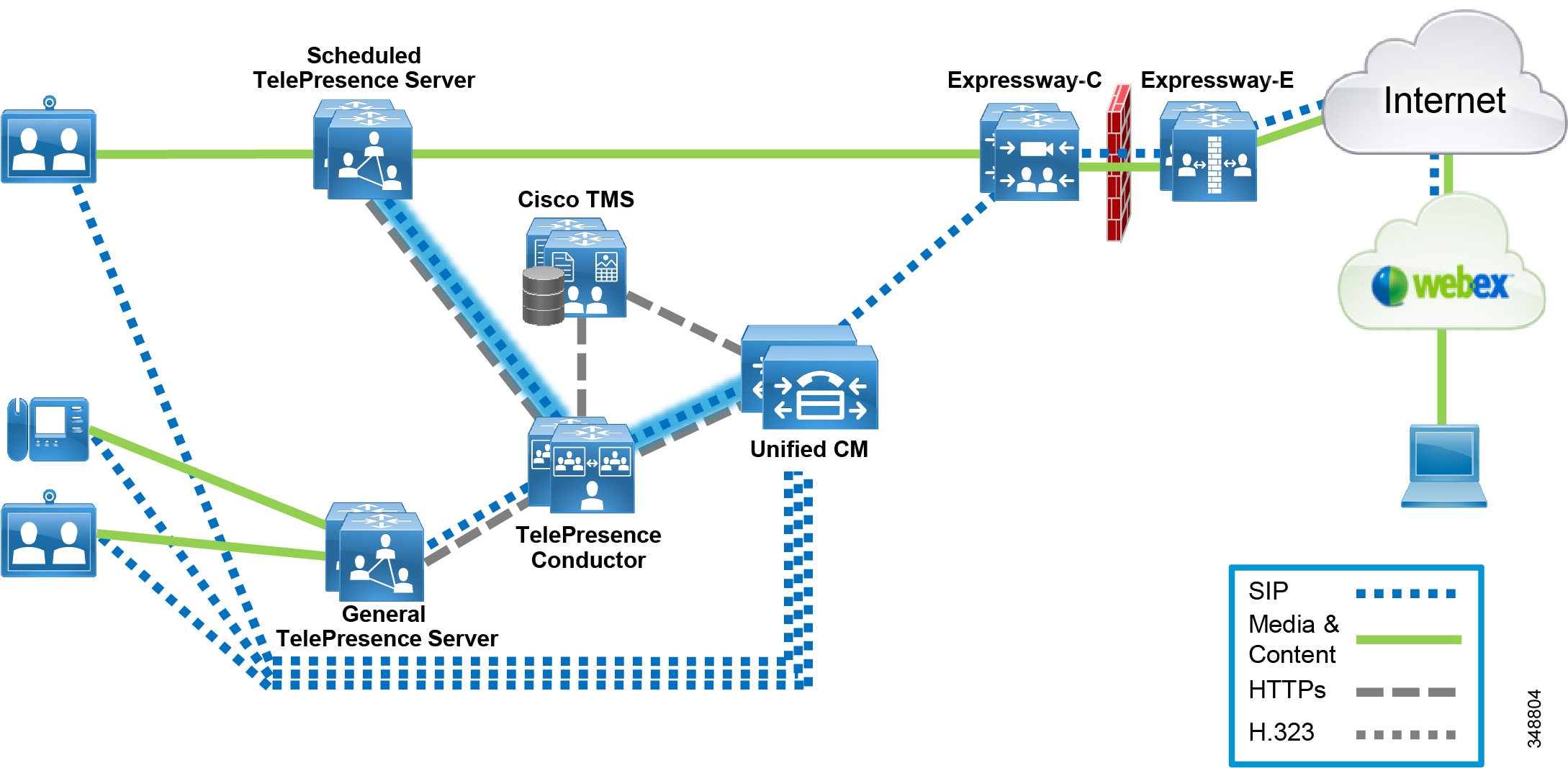
Scheduled conferences, including CMR Hybrid meetings for participation by Cisco WebEx users, are supported on Cisco TelePresence Server 7010 and MSE 8710 conference bridges. The bridges may be connected directly to Unified CM or through TelePresence Conductor. Figure 11-1 shows two dedicated TelePresence Servers used for scheduled and Cisco WebEx conferences, where scheduling bridges are connected via SIP to TelePresence Conductor and Unified CM engages TelePresence Conductor via SIP to establish the video conferences.
Figure 11-1 Scheduling with TelePresence Conductor and Dedicated Resources
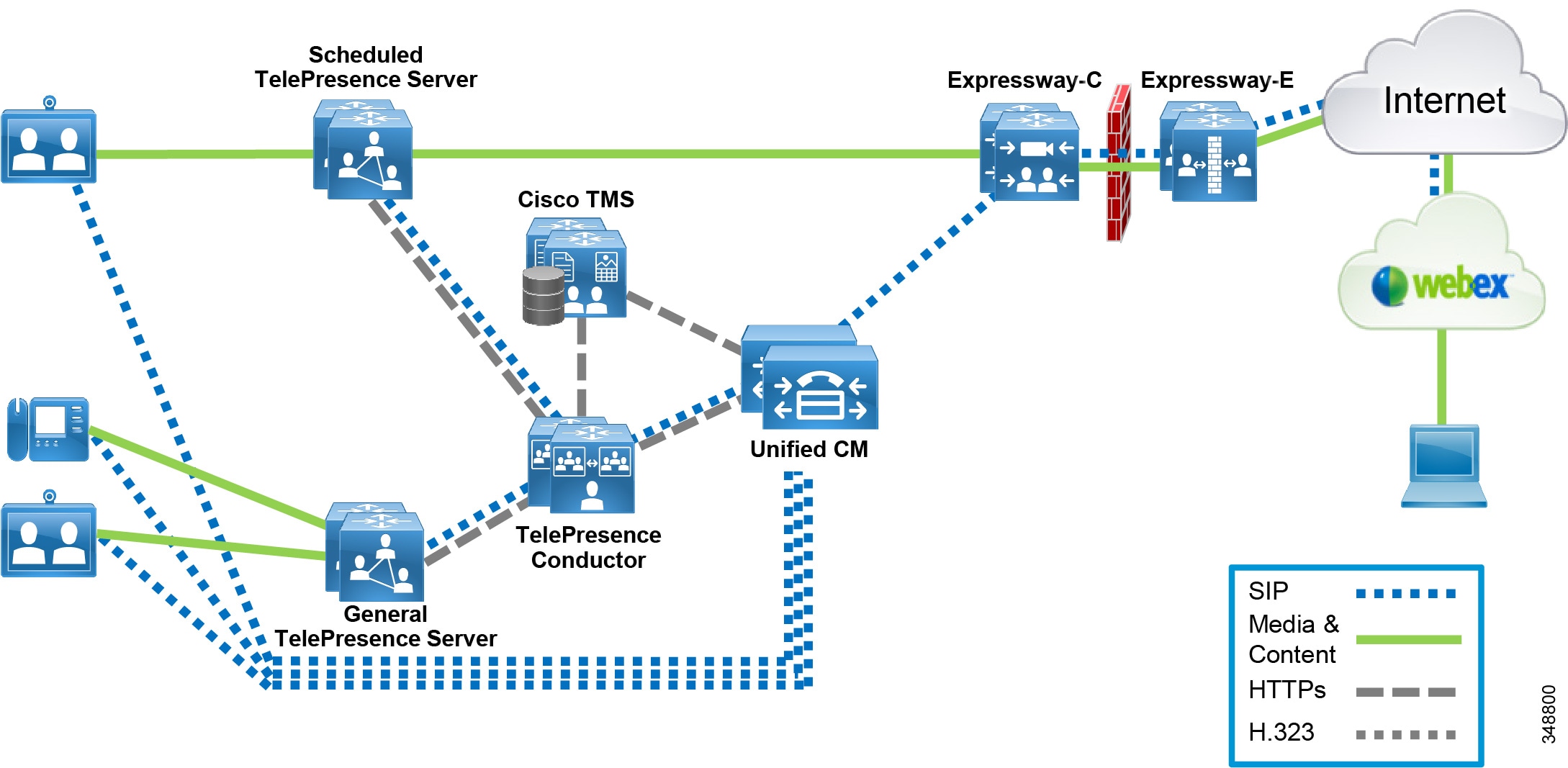
Figure 11-1 illustrates a design where TelePresence Conductor manages both scheduled and non-scheduled conference bridges. This is a newly supported design in Cisco Collaboration System Release (CSR) 10.6. In this architecture, scheduled conferences can be dedicated for scheduling as indicated in Figure 11-2 or, as indicated in Figure 11-3, shared (not dedicated) with a pool of TelePresence Servers (General TelePresence Server in the illustration) that are grouped together and used on a first-come-first-served basis by TelePresence Conductor for instant, permanent, and scheduled conferencing (see Deployment Considerations, for more information).
Figure 11-2 shows multiple shared TelePresence Servers used for both scheduled and non-scheduled conferences as well as Cisco WebEx conferences. In this design, scheduling bridges are connected via SIP to TelePresence Conductor, and Unified CM engages TelePresence Conductor directly via SIP to establish the video conferences.
Figure 11-2 Scheduling with TelePresence Conductor and Shared Resources
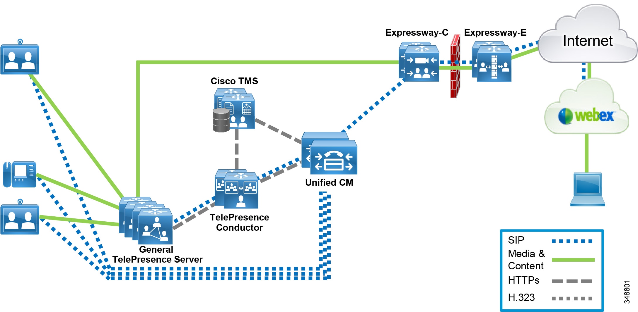
Figure 11-3 shows two dedicated TelePresence Servers used for scheduled and Cisco WebEx conferences, where scheduling bridges are directly connected via SIP to Unified CM. This is a legacy design and was supported prior to Collaboration System Release 10.6.
Figure 11-3 Scheduling without TelePresence Conductor
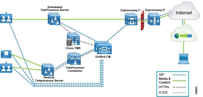
Figure 11-3 illustrates a design where TelePresence Conductor manages the non-scheduled bridges for instant and permanent (General TelePresence Server) conferencing while the scheduled bridges (Scheduled TelePresence Server) are directly connected to Unified CM via SIP. SIP trunks are used for call control between the General TelePresence Server bridges and the TelePresence Conductor, between the Scheduled TelePresence Server bridges and the Unified CM, and between the TelePresence Conductor and Unified CM. XML-RPC (Remote Procedure Call) over HTTPs is used as an application programming interface (API) for resource control as well as provisioning and management. Cisco TMS also uses XML-RPC over HTTPs to link to the TelePresence Conductor for provisioning and directly to the TelePresence Servers for scheduled conference management as well as connecting to Unified CM for endpoint discovery and resource booking.
Scheduled resources such as the Cisco TelePresence Server 7010 and MSE 8710 bridges are directly connected to Unified CM and TMS and must be configured in locally managed mode. Scheduled conferencing is not supported on the TelePresence Server on Multiparty Media 310 or 320, nor on the Cisco TelePresence Server on Virtual Machine, because they cannot operate in this mode.
A number of different designs can be implemented, depending on the conferencing requirements of the desired solution. Some of those requirements include:
Audio-Only Versus Video Conferencing
For audio-only conferencing, Cisco recommends using Unified CM as the conferencing manager and using hardware conference bridges on the Cisco Integrated Services Router. See Audio Conferencing, for further details.
For video conferencing, Cisco recommends using TelePresence Conductor for centralized management of the video conferencing solution with TelePresence Server as the conferencing bridge of choice for both audio-only and video conferencing, and any combination thereof achieved through screen licenses.
For more information about screen licenses per call type, that cover audio-only licensing, refer to the Cisco TelePresence Server Data Sheet available at
http://www.cisco.com/c/en/us/products/conferencing/telepresence-server/datasheet-listing.html
Scheduled Versus Non-Scheduled Conferencing
Scheduled conferencing utilizes a scheduling management system such as Cisco TelePresence Management Suite (TMS). Conferences are booked via Cisco TMS with a start and end time, and optionally with a predefined set of participants. TMS can be utilized for scheduling in either of the following two distinct designs.
TMS Scheduling without TelePresence Conductor
In this first design, the solution supports scheduling of conferences on TMS with bridges directly engaged by Unified CM rather than via the TelePresence Conductor.
Scheduling is performed with Cisco TMS, using Microsoft Outlook, through Cisco TelePresence Management Suite Extension for Microsoft Exchange (TMSXE). Scheduled conferences, including CMR Hybrid meetings for participation by Cisco WebEx users, are supported on Cisco TelePresence Server 7010 and MSE 8710 conference bridges. The bridges must be connected directly to Unified CM and not through TelePresence Conductor, and configured in locally managed mode. Figure 11-4 shows two dedicated TelePresence Servers used for scheduled and Cisco WebEx conferences for CMR Hybrid. A SIP trunk is configured directly between the TelePresence Servers and Unified CM to enable Unified CM to engage the bridge resources in the scheduled conferencing call flows.
Figure 11-4 TMS Scheduling without TelePresence Conductor
TMS Scheduling with TelePresence Conductor
In this second design, the solution supports scheduling on TMS with conferencing bridges engaged by the TelePresence Conductor. Scheduling is performed with Cisco TMS, using Microsoft Outlook, through TMSXE. Scheduled conferences, including CMR Hybrid meetings for participation by Cisco WebEx users, are supported on Cisco TelePresence Server 7010 and MSE 8710 conference bridges. The bridges must be connected directly to TelePresence Conductor and in remotely managed mode. Figure 11-5 shows two dedicated TelePresence Servers used for scheduled and Cisco WebEx conferences connected to and managed by TelePresence Conductor. A SIP trunk is configured between Unified CM and TelePresence Conductor, and between TelePresence Conductor and the TelePresence Servers. In these scheduled conferencing call flows, Unified CM communicates directly with TelePresence Conductor to request the conferencing resources.
Figure 11-5 TMS Scheduling with TelePresence Conductor
Deployment Considerations
The physical location of a TelePresence Server is important to consider because media traffic flows between it and each participant in the conference. To provide the best experience for participants, centralize the location of the TelePresence Servers in each region where they will be deployed.
Figure 11-6 illustrates the deployment differences between remotely and locally managed modes. Set the TelePresence Servers to remotely managed mode, which is a system-wide setting that enables a more advanced API and requires that API to be used for all operations. Remotely managed mode is the only mode available on the Cisco TelePresence Server on Virtual Machine and Cisco TelePresence Server on Multiparty Media 310 or 320, while other variants of the TelePresence Server have a locally managed mode that cannot be used with TelePresence Conductor.
Figure 11-6 TelePresence Server Modes
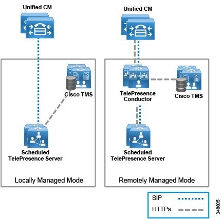

TelePresence Conductor manages the TelePresence Servers via an XML-RPC over HTTPs API. TelePresence Conductor also routes SIP signaling to the TelePresence Servers via its Back-to-Back User Agent (B2BUA).
The TelePresence Server has the ability to use a secure connection for communications. These security features are enabled with the encryption feature key. The encryption feature key is required for TelePresence Conductor to communicate with the TelePresence Server; unencrypted communication is not supported.
Interworking H.323 Endpoints into a SIP Environment
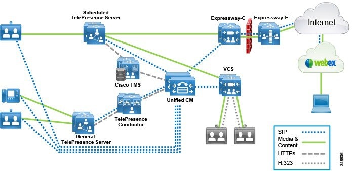
Many designs require the ability to incorporate H.323 endpoints into the architecture and to ensure interworking with a SIP-based design. The Cisco Video Communication Server (VCS) can be used to interwork these H.323 endpoints into a SIP-based design to provide features such as H.323-to-SIP conversion for call control, H.239-to-BFCP conversion for presentation sharing, and H.235-to-SIP for SRTP conversion. Figure 11-7 illustrates a conferencing design with VCS interworking the H.323 endpoints with SIP to Unified CM to access the SIP-based rich media conferencing solution.
Figure 11-7 Architecture Overview for H.323 Interworking
Design Considerations for Audio and Video Conferencing
The following sections provide general information and an explanation about the resources used in the conferencing architecture, as well as best practices for the conference types that use those resources.
Audio Conferencing
If you are deploying a large-scale video conferencing solution, Cisco recommends also deploying audio conferencing as part of that solution. The video conferencing solution requires TelePresence Conductor and TelePresence Server, which can also be used for audio conferencing. This reduces the complexity and total cost of ownership of the overall conferencing solution.

Note![]() TelePresence Server does not support any advanced audio bridge functionality such as join or leave tones, or any form of in-meeting control.
TelePresence Server does not support any advanced audio bridge functionality such as join or leave tones, or any form of in-meeting control.
If you are deploying an audio-only conferencing solution, Cisco recommends using Unified CM to manage the conferencing resources.
It is important to note that a video multipoint resource can be used for audio-only conferences, but audio-only conferencing resources cannot be used for the audio portion of video conferences.
Audio conferencing can be performed by both software-based and hardware-based conferencing resources. A hardware conference bridge has all the capabilities of a software conference bridge. In addition, some hardware conference bridges can support multiple low bit-rate (LBR) stream types such as G.729 or G.723. This capability enables some hardware conference bridges to handle mixed-mode conferences. In a mixed-mode conference, the hardware conference bridge transcodes G.729 and G.723 streams into G.711 streams, mixes them, and then encodes the resulting stream into the appropriate stream type for transmission back to the user. Some hardware conference bridges support only G.711 conferences.
All voice conference bridges that are under the control of Cisco Unified Communications Manager (Unified CM) use Skinny Client Control Protocol (SCCP) to communicate with Unified CM.
Unified CM allocates a conference bridge from a conferencing resource that is registered with the Unified CM cluster. Both hardware and software conferencing resources can register with Unified CM at the same time, and Unified CM can allocate and use conference bridges from either resource. Unified CM does not distinguish between these types of conference bridges when it processes a conference allocation request.
The number of individual conferences that can be supported by the resource varies, and the maximum number of participants in a single conference also varies, depending on the resource.
Although Cisco Unified CM supports a wide variety of conference bridges, Cisco recommends the following hardware conference bridge resources over legacy conference bridges for Unified CM audio conferencing: Cisco NM-HDV2, NM-HD-1V/2V/2VE, PVDM2, and PVDM3 DSPs.
Instant Audio Conference
This type of conference can be created by a user invoking the Conf function of the Cisco Collaboration endpoint. Cisco Unified CM supports integration of hardware conference bridges for this kind of audio conference. The conference bridge needs to be defined as a media resource in Unified CM for it to be available during the bridge selection process.
Only the following event invokes instant conference bridge resources:
The user of an SCCP or SIP endpoint presses the Conf, Join, or cBarge softkey to invoke an instant conference.
Participants in this type of conference can include any type of endpoint (that is, video and non-video devices using any signaling protocol that Unified CM supports via any supported gateway type); however, only Cisco Collaboration endpoints or clients that have available the Cisco Unified CM Conf key functionality can initiate the instant conference. In other words, an H.323 video endpoint cannot initiate an instant audio conference resource, but a video-enabled Cisco Unified IP Phone 9971 can invoke the conferencing resource and then join an H.323 video participant to the call. For example, the user at the Unified IP Phone 9971 could press the Conf key, dial the directory number of an H.323 client, and then press the Conf key again to complete the transaction. The H.323 client in this case would be joined as a participant on the instant audio conference.
Meet-Me Audio Conference
A meet-me audio conference is a permanent conference type. For meet-me audio conferencing, the conference initiator creates the conference ahead of time by invoking the MeetMe function of the Cisco Collaboration endpoint. The conference initiator then distributes the MeetMe number to the attendees so they can dial in. The conference bridge needs to be defined as a media resource in Cisco Unified CM and must be available to the conference initiator for the meet-me audio conference to be possible.
Scheduled Audio Conference
Traditionally, audio conferencing is created through instant or permanent methods; however, scheduling for audio conferences is also available through the integration of Cisco Collaborative Conferencing. For further information, see Cisco Collaboration Services.
Security in Audio Conferences
Secure conferencing is a way to use regular conferencing to ensure that the media for the conference is secure and cannot be compromised. There are various security levels that a conference can have, such as authenticated or encrypted. With secure conferencing, the devices and conferencing resources can be authenticated to be trusted devices, and the conference media can then be encrypted so that every authenticated participant sends and receives encrypted media for that conference. In most cases the security level of the conference depends on the lowest security level of the participants in the conference. For example, if there is one participant who is not using a secure endpoint, then the entire conference will be non-secure. As another example, if one of the endpoints is authenticated but does not do encryption, then the conference will be in authenticated mode.
Secure conferencing provides conferencing functionality at an enhanced security level and prevents unauthorized capture and decryption of conference calls.
Consider the following factors when designing secure conferencing:
- Security levels of devices (phones and conferencing resources)
- Bandwidth overhead for call signaling and secure (SRTP) media
- Bandwidth utilization impact if secure participants are across the WAN
- Any intermediate devices such as NAT and firewalls that might not support secure calls across them
Secure conferencing is subject to the following restrictions and limitations:
- Secure conferencing can use more DSP resources than non-secure conferencing, so DSPs must be provisioned according to the DSP Calculator. For further information, see the section on Sizing the Conferencing Resources.
- Some protocols might rely on IPSec to secure the call signaling.
- Secure conferencing cannot be cascaded between Unified CM and Unified CM Express.
- Media termination points (MTPs) and transcoders do not support secure calls. Therefore, a conference might no longer be secure if any call into that conference invokes an MTP or a transcoder.
- An elaborate security policy set in place by the IT staff for equipment usage might be needed.
- Secure conferencing might not be available for all codecs.
The number of individual conferences that can be supported by the resource varies, and the maximum number of participants in a single conference also varies, depending on the resource.
Video Conferencing
When integrated with the Cisco Rich Media Conferencing architecture, video-capable endpoints provide the capability to conduct video conferences that function similar to audio conferences. Video conferences can be instant, permanent, or scheduled. This section discusses the following main topics:
- Meeting Experience
- Instant Video Conferences
- Permanent Video Conferences
- Scheduled Video Conferences
Videoconferencing resources are hardware or software types, and currently the main difference between software and hardware video resources is capacity:
Software videoconferencing bridges process video and audio for the conference using just software.
Hardware videoconferencing bridges have hardware DSPs that are used for the video conferences. The Cisco TelePresence MSE 8000 Series, Cisco TelePresence MCU 5300 Series, Cisco TelePresence Server, and in the case of Cisco Unified CM, the PVDM3 DSPs (with Cisco IOS Release 15.1.4M and later releases) provide this type of videoconferencing bridge. Most hardware videoconferencing bridges can also be used as audio-only conference bridges. Hardware videoconferencing bridges provide the advantage of more capacity than software videoconferencing bridges.
Meeting Experience
The video portion of the conference can operate in one of three meeting experience modes, depending on the conferencing device:
- Full-Screen Voice Activation, (TelePresence Server or MCU)
- Continuous Presence, (TelePresence Server or MCU)
- Cisco ActivePresence, (TelePresence Server)
In addition, video conferencing can use any of the following methods to select the dominant speaker:
- Voice Activation Mode
- Manual Selection of the Dominant Speaker
- Automatic Participant List Cycling, (Not available for Cisco TelePresence Server)
Full-Screen Voice Activation
Voice-activated conferences take in the audio and video streams of all the participants, decide which participant is the dominant speaker, and send only the dominant speaker's video stream back out to all other participants. The participants then see a full-screen image of the dominant speaker (and the current speaker sees the previous dominant speaker). The audio streams from the participants (four in the case of the Cisco TelePresence MCU and Cisco TelePresence Server) are mixed together, so everyone hears everyone else, but only the dominant speaker's video is displayed. This mode is optimal when one participant speaks most of the time, as with an instructor teaching or training a group. Speaker (segment) switching and room switching fall under this category.
Continuous Presence
Continuous-presence conferences display some or all of the participants together in a composite view. The view can display the participants in a variety of layouts. Each layout offers the ability to make one of the squares voice-activated, which is useful if there are more participants in the conference than there are squares to display them all in the composite view. For instance, if you are using a four-way view but there are five participants in the call, only four of them will be displayed at any given time. You can make one of the squares in this case voice-activated so that participants 5 and 6 will switch in and out of that square, depending on who is the dominant speaker. The participants displayed in the other three squares would be fixed, and all of the squares can be manipulated through the conference control web-based user interface, DTMF (in the case of the Cisco TelePresence MCU and Cisco TelePresence Server), and Far End Camera Control (FECC, in the case of the Cisco TelePresence Server).On the other hand, if you are using the "equal panels layout family," the layout would change to 3x3 when the sixth participant joins. The audio portion of the conference follows or tracks the dominant speaker. Continuous presence is more popular than voice switching, and it is optimal for conferences or discussions between speakers at various sites.
Cisco ActivePresence
The Cisco ActivePresence capability of Cisco TelePresence Server, a leading patent-pending feature, enables the delivery of next-generation multipoint conferencing by offering a view of all attendees in a meeting while giving prominence to the active speaker. While the active speaker occupies most of the screen, an overlay of others in the call appears in the lower third of the screen. This maintains the immersive feel of the life-size main speakers while giving participants a more natural view of everyone else sitting around the virtual table.
Voice Activation Mode
Using this mode, the video conference bridge automatically selects the dominant speaker by determining which conference participant is speaking the loudest and the longest. To determine loudness, the MCU calculates the strength of the voice signal for each participant. As conditions change throughout the conversation, the MCU automatically selects a new dominant speaker and switches the video to display that participant. A hold timer prevents the video from switching too hastily. To become the dominant speaker, a participant has to speak for a specified number of seconds and be more dominant than all other participants.
Manual Selection of the Dominant Speaker
The dominant speaker might be selected through the MCU's web-based conference control user interface. A user with privileges to log onto the MCU's web page, highlights a participant and selects that person as the important or dominant speaker. This action disables voice activity detection, and the dominant speaker remains constant until the chairperson either selects a new dominant speaker or re-enables voice activation mode.
Automatic Participant List Cycling
With this method, the MCU is configured to cycle through the participant list automatically, one participant at a time. The MCU stays on each participant for a configured period of time and then switches to the next participant in the list. The conference controller (or chairperson) can turn this feature on and off (re-enable voice activation mode) from the web interface.
Instant Video Conferences
Instant video conferences can be accomplished using embedded video resources (MultiSite) or dedicated video resources. The method for initiating an instant conference varies according to the call control used to initiate it. Cisco Collaboration endpoints managed by Cisco Unified CM can initiate the conference through the use of Conf, Join, or cBarge keys or the Add function (for endpoints with the MultiSite functionality), endpoints managed by Cisco VCS can initiate the conference by making use of Multiway or MultiSite functionality.
This section discusses how instant conferences occur with embedded and dedicated resources.
Note![]() For H.323 and SIP clients with built-in MCUs, Unified CM allows functionality of the endpoint’s built-in MCU only if the client is SIP.
For H.323 and SIP clients with built-in MCUs, Unified CM allows functionality of the endpoint’s built-in MCU only if the client is SIP.
MultiSiteTM
Certain endpoints are capable of escalating point-to-point calls with two endpoints to conferences with three or more endpoints, without the need for an external dedicated device. In Cisco Rich Media Conferencing this ability is referred to as MultiSite TM. The conference created using MultiSite is considered instant because it usually happens without prior planning and scheduling (see Figure 11-8). An option key is required to unlock the MultiSite feature. MultiSite conferences use the embedded resources in the endpoint for the conference creation. Endpoints with MultiSite capability that have the key installed can invoke this conference type whether they are managed by Cisco Unified CM or Cisco VCS.
Figure 11-8 Point-to-Point Call Escalated to Instant Conference Using Embedded Resources (MultiSite)

Instant Conferences Using Dedicated Devices
While many video endpoints on the market today are incapable of hosting conferences themselves and require an additional device to handle mixing the multiple video and audio streams, key factors for selecting dedicated video resources over embedded resources are bandwidth usage centralization, scalability, and cost efficiency. These multipoint resources are shared by a number of endpoints and are capable of hosting many conferences at the same time. The method in which a dedicated resource is invoked depends on the endpoints and the call control device(s) involved. In the case of users utilizing devices that can and are registered natively to Cisco Unified CM, the users can initiate an instant video conference with dedicated resources by using the Conf, Join, or cBarge keys.
Figure 11-9 illustrates one example of an instant conference using an external resource.
Figure 11-9 Instant Conference with a Dedicated Conferencing Device

Currently the MCU and Cisco TelePresence Server (when used in conjunction with Cisco TelePresence Conductor) are the only dedicated resources that enable instant calls for TelePresence endpoints controlled by Cisco VCS. The Cisco PVDM3 module can be added to this list for endpoints controlled by Cisco Unified CM.
Permanent Video Conferences
Permanent conferences can be initiated in three different ways depending on the call control used by the conference initiator. Cisco Unified CM supports video meet-me, MCU-IVR dial-in, and preconfigured permanent alias video conference initiation methods. Figure 11-10 depicts an example of a permanent conference taking place.
The main differences between video meet-me conferences and preconfigured permanent alias video conferences is the launch method. The user initiates a meet-me conference through a softkey, while the permanent alias for a video conference is always available after it has been preconfigured by the administrator and the user needs to dial the alias to join the conference.
Figure 11-10 Example of a Permanent Conference

The Cisco TelePresence multipoint devices may use different names for permanent conferences, referring to them as permanent conferences or static conferences.
IVR for Dial-in Conference
Dial-in conferences can optionally use an interactive voice response (IVR) system to prompt users to enter the conference ID and the password (if one is configured) of the conference they want to join. You can use either of the following types of IVRs with the Cisco MCUs:
The built-in IVR of the MCU has the following characteristics:
- Can prompt to create a conference or join by conference ID
- Can prompt for the password of the conference
- Supports both in-band and out-of-band (H.245 alphanumeric) DTMF
- Cannot be customized to provide more flexible menus or functionality
The only items that the user can customize are the recorded audio file that is played to the user and the logo at the top of the screen.
If you want to have a single dial-in number and then prompt the user for the conference ID, you can use Cisco Unified IP IVR in conjunction with the MCU. Cisco Unified IP IVR has the following characteristics:
- Only applicable for Cisco Unified CM integrations
- Can prompt for the conference ID and the password (among other things)
- Supports only out-of-band DTMF
That is, the calling device must support an out-of-band DTMF method (such as H.245 alphanumeric) on H.323 devices. These out-of-band DTMF messages are then relayed by Unified CM to the Cisco IP IVR server. If the calling device supports only in-band DTMF tones, the Cisco IP IVR server will not recognize them and the calling device will be unable to enter the conference.
Customizations can include such things as verifying the user's account against a back-end database before permitting that user to enter into the conference, or queuing the participants until the chairperson joins.
Note![]() Because Cisco Unified IP IVR supports only out-of-band signaling, it will not work with endpoints that use in-band DTMF tones.
Because Cisco Unified IP IVR supports only out-of-band signaling, it will not work with endpoints that use in-band DTMF tones.
With Cisco Unified IP IVR, users dial a CTI route point that routes the call to the Cisco Unified IP IVR server instead of dialing a route pattern that routes directly to the MCU. After collecting the DTMF digits of the conference ID, the Cisco Unified IP IVR then transfers the call to the route pattern that routes the call to the MCU. This transfer operation requires that the calling device supports having its media channels closed and reopened to a new destination. For example, an H.323 video device that calls the Cisco Unified IP IVR will initially negotiate an audio channel to the Cisco Unified IP IVR server and then, after entering the appropriate DTMF digits, it will be transferred to the MCU, at which point Unified CM will invoke the Empty Capabilities Set (ECS) procedure to close the audio channel between the endpoint and the Cisco Unified IP IVR server and open new logical channels between the endpoint and the MCU. If the H.323 video endpoint does not support receiving an ECS from Unified CM, it will react by misbehaving or disconnecting the call.
Scheduled Video Conferences
Cisco Unified CM 10.5.2 and later releases, TelePresence Conductor 3.0, TelePresence Server 4.1, Expressway X8.5, and TelePresence Management Suite (TMS) 14.6 support SIP MCUs for scheduled video conferences. Because SIP is the protocol of choice in Unified CM, Cisco recommends registering any H.323 MCUs to a Cisco TelePresence Video Communication Server (VCS) as a gatekeeper, and configuring H.323-SIP interworking from the VCS to Unified CM to provide support for scheduled video conferences when only H.323 MCUs are available in the infrastructure.
Scheduled video conferences provide users with a guarantee that multipoint resources will be available at the conference start time. Scheduled conferences can be joined in a variety of ways, as Table 11-2 describes.
Scheduling ensures endpoint and port resource availability and provides convenient methods to connect to TelePresence conferences. Most organizations already use calendaring applications to schedule conferences. In this case, calendaring integration enables users to schedule conferences with their existing calendaring client. TelePresence deployments often include a large quantity of endpoints and different infrastructure components. Without a centralized management component, provisioning, monitoring, and resource allocation are difficult if not impossible. Management platforms greatly simplify these processes.
The Cisco TelePresence scheduling and management options you choose depend on the type of calendaring your organization uses, the type of TelePresence deployment selected or already implemented by your organization, and the requirements or preferences of your organization.
Scheduled meetings work by integrating TelePresence resources and endpoints with corporate calendaring applications (see Figure 11-11). Cisco TelePresence Management Suite (TMS) resides between endpoints and calendaring applications to locate the proper multipoint resource for each scheduled conference, and to provide resource reservation. Both the TelePresence Server and the MCU are capable of creating scheduled conferences without the aid of the TelePresence Management Suite or TelePresence Manager; however, in this case only the multipoint device is scheduled, but the endpoints themselves are not guaranteed to be available. For this reason Cisco recommends deploying scheduled conferencing with the TelePresence Management Suite and creating conferences by scheduling three or more endpoints.
Figure 11-11 Scheduled Conference Using Integration with a Calendaring Application

Security in Video Conferences
Unified CM supports secure conferencing with SIP MCU integration types. With secure conferencing, Unified CM uses HTTPS to communicate to the MCU for conference scheduling, it uses TLS for call signaling, and it uses SRTP for media payload encryption. However, the conference is secure only if all the participants' endpoints support video encryption.
Alternatively, Cisco VCS supports secure conferencing in environments with H.323 and SIP MCUs. Cisco VCS can also offer security interworking between H.235 and SRTP, thus making it better suited for deployments in which security is used with SIP and H.323 protocols.
For more information about secure conferencing, see the chapter on Cisco Collaboration Security.
Conferencing Resources
A conferencing resource is the hardware-based or software-based entity that performs the media conferencing, multiplexing, or media switching functions for the Cisco Rich Media Conferencing Architecture. This section provides overall guidance on the most appropriate uses of each of the following conferencing resources
–![]() Dedicated Audio Conferencing Resources
Dedicated Audio Conferencing Resources
Software Audio Conference Bridge
Hardware Audio Conference Bridge
–![]() Embedded Audio Resources (Built-in Bridge)
Embedded Audio Resources (Built-in Bridge)
Cisco TelePresence Multipoint Control Unit (MCU)
Cisco Packet Voice Digital Signal Processor Module (PVDM3)
Audio Conferencing Resources
As stated earlier, Cisco VCS always invokes a video conference bridge MCU for any type of conference, even if its participants are capable of audio-only conferences. Therefore, the information on audio conferencing resources in this section applies only to Cisco Unified CM audio conferences.
The audio conference resources have different purposes depending on whether they are dedicated or embedded. Although some can be used interchangeably under some situations, not all of them can.
Dedicated Audio Conferencing Resources
A dedicated audio resource is an entity whose sole purpose is conference creation, and it stands apart from the endpoint. Dedicated resources can be either software-based or hardware-based.
Software Audio Conference Bridge
The software-based audio conference bridges are provided by the IP Voice Media Streaming Application on Unified CM. The application must be enabled on each individual node in a cluster. A software unicast conference bridge is a standard conference mixer that is capable of mixing G.711 audio streams and Cisco Wideband audio streams. Any combination of Wideband or G.711 a-law and mu-law streams may be connected to the same conference. The number of conferences that can be supported on a given configuration depends on the server where the conference bridge software is running and on what other functionality has been enabled for the application. However, 256 is the maximum number of audio streams for this type. With 256 streams, a software conference media resource can handle 256 users in a single conference, or the software conference media resource can handle up to 64 conferencing resources with four users per conference. If the Cisco IP Voice Media Streaming Application service runs on the same server as the Cisco CallManager Service, a software conference should not exceed the maximum limit of 48 participants.
The Cisco IP Voice Media Streaming Application is a resource that can also be used for several functions, and the design must consider all functions together (see Cisco IP Voice Media Streaming Application). Since the capabilities of the software audio conference bridge are limited, Cisco recommends using a software audio conference bridge only in centralized deployments or in deployments where the use of a G.711 codec is acceptable for instant and meet-me audio conferencing. It is also important to note that the use of a software audio conference bridge in Unified CM will result in a higher load on the system than otherwise would be present.
Hardware Audio Conference Bridge
Digital signal processors (DSPs) that are configured through Cisco IOS as conference resources load firmware into the DSPs that are specific to conferencing functionality only, and these DSPs cannot be used for any other media feature. Any Cisco PVDM2 or PVDM3 hardware, such as the Cisco NM-HDV2 Network Module, may be used simultaneously in a single chassis for voice termination but may not be used simultaneously for other media resource functionality. The DSPs based on PVDM-256K and PVDM2 have different DSP farm configurations, and only one may be configured in a router at a time. DSPs on PVDM2 hardware are configured individually as voice termination, conferencing, media termination, or transcoding, so that DSPs on a single PVDM may be used as different resource types. Allocate DSPs to voice termination first, then to other functionality as needed.
The DSP resources for a conference are reserved during configuration, based on the profile attributes and irrespective of how many participants actually join. Refer to the following module data sheets for accurate information on module capacities and capabilities:
- For capacity information on PVDM2 modules, refer to the High-Density Packet Voice Digital Signal Processor Module for Cisco Unified Communications Solutions data sheet, available at
http://www.cisco.com/en/US/prod/collateral/routers/ps5854/product_data_sheet0900aecd8016e845_ps3115_Products_Data_Sheet.html
- For capacity information on PVDM3 modules, refer to the High-Density Packet Voice Video Digital Signal Processor Module for Cisco Unified Communications Solutions data sheet, available at
http://www.cisco.com/en/US/prod/collateral/modules/ps3115/data_sheet_c78-553971.html
Hardware audio conference bridges offer a wider range of capabilities and codec format support than the software conference bridges. Cisco recommends using hardware audio conference bridges where the enterprise requires a more versatile audio conference bridge and codec support for higher-complexity codecs such as G.729 to take advantage of bandwidth savings.
Embedded Audio Resources (Built-in Bridge)
Embedded resources refer to the DSP resources that are hosted by one of the endpoints in the call. Certain Cisco IP Phones have an on-board DSP for the built-in bridge functionality. The IP phone built-in bridge is the only embedded audio resource in the Cisco Rich Media Conferencing architecture. The built-in bridge, however, has limited conference functionality and cannot be used to launch a full conference. The built-in bridge in the Cisco IP Phones allows a user to:
- Join calls across different lines that the IP phone might have, and convert those calls into a conference hosted on the built-in bridge
- Barge into a call of a different endpoint that shares the line (if the call is not set to private), and convert the call into a conference hosted on the built-in bridge
- Start a silent recording or monitoring session from the endpoint that is engaged on a call, and fork the media generated and received by the phone invoking the feature
The built-in bridge of the Cisco IP Phones can encode and decode G.711 and G.729 codec formats. However, once the codec for the call has been selected, the built-in bridge codec selection is locked and the phone will be unable to change the codec used. Therefore, the best practice is to carefully analyze the call flow in which the built-in bridge might be invoked to avoid call drops.
The built-in bridge can mix a maximum of two calls and can fork only one call (two streams).
Video Conferencing Resources
The actual entity which hosts a multipoint conference may reside within a video endpoint or be separate from the endpoint in a dedicated device whose resources are shared by many endpoints. In many customer environments both options can be deployed. It is also important to understand that the video conferencing functionality is achieved by media transcoding and media switching, refer to the Design and Considerations for Cisco Rich Media Conferencing section of this chapter for further information about the differences of transcoding and switching in video conferencing.
Dedicated Video Resources
Cisco has a wide range of dedicated devices for audio and video conferencing. The following devices are relevant to Cisco Video Collaboration endpoints:
- Cisco TelePresence Server
- Cisco TelePresence Multipoint Control Unit (MCU)
- Cisco Packet Voice Digital Signal Processor Module (PVDM3)
The dedicated conferencing device mixes the audio and video streams from each video endpoint and transmits a single audio and video stream back to each endpoint. In the case of multi-screen endpoints, multiple audio and video streams may be sent and received by the conferencing device.
Using a dedicated device has the following benefits:
- Greater scalability
- Enhanced feature sets (auto attendants, scheduling, presenter modes, and so forth)
- Higher quality user experience
- Reduced cost compared to enabling embedded conferencing on large numbers of endpoints
The Cisco TelePresence Server is a transcoding multipoint device that is available as the Cisco TelePresence Server 7010 appliance or the Cisco TelePresence Server MSE 8710 blade for the Cisco MSE 8000 Series chassis. Cisco TelePresence Server is also supported on virtual machines (Cisco TelePresence Server on Virtual Machine). The TelePresence Server can connect many video and audio devices using a variety of protocols, including SIP, H.323, and TIP. Currently it is the only Cisco multipoint device that supports both TIP and non-TIP multi-screen systems. The TelePresence Server is capable of permanent and scheduled conferences, and it can also support instant conferencing when working in conjunction with Cisco TelePresence Conductor. Cisco recommends using Cisco TelePresence Server for all video conferencing.
The Cisco TelePresence Server 7010 and MSE 8710 support the locally managed mode listed in Table 11-3 , which in turn affects the supported resolutions and capacity. Table 11-3 also describes the differences between these options. All other versions of Cisco TelePresence Server can be run only in remotely managed mode.
For more information about clustering with the TelePresence Server MSE 8000 Series, refer to the latest version of the Cisco TelePresence Server Product User Guide, available at
http://www.cisco.com/en/US/partner/products/ps11339/products_user_guide_list.html
Cisco TelePresence Multipoint Control Unit (MCU)
The Cisco TelePresence Multipoint Control Unit (MCU) portfolio offers flexibility for a variety of video deployments. The MCUs are designed for single-screen Cisco and non-Cisco video endpoints using standards-based H.323 and SIP call signaling. The user's experience can vary depending upon which of the many custom screen layouts is chosen for a particular conference. The MCU supports instant, permanent, and scheduled conferences. Depending on the model, Cisco MCUs can support resolutions from QCIF up to 1080p in 4:3 and 16:9 aspect ratios and can support the video modes listed in Table 11-4 .
A global configuration setting on the MCU enables one of these modes, which in turn affects the supported resolutions and capacity. Port count depends on which mode is enabled because HD, HD+, and Full HD settings require more hardware resources than the lower-resolution SD setting. Table 11-4 describes the differences between these options.
Cisco recommends the using dedicated video resources for greater conference scalability and when a large number of endpoints will be deployed in the organization. Cisco TelePresence MCUs can be pooled together and manage by Cisco TelePresence Conductor for increased flexibility.
When deciding which multipoint device to deploy, it is important not only to understand their audio and video capabilities, but also to know which features are supported on each device. Table 11-5 summarizes feature support for the multipoint devices.
Cisco Packet Voice Digital Signal Processor Module (PVDM3)
The Cisco Packet Voice Digital Signal Processor Module PVDM3 is a hardware module that provides digital signal processor (DSP) resources. The PVDM3 is the latest iteration of the DSP conferencing technology available for the Cisco Integrated Service Routers Generation 2(ISR G2). Cisco has introduced the ability to do multipoint video conferencing for instant and permanent (MeetMe) video conferences with ISR G2 routers and Cisco Unified Communications Manager (Unified CM) when the PVDM3 is used as a media resource. This ability is available only when Cisco Unified CM is used as call control in conjunction with the PVDM3 module and the endpoint supports the native instant conferencing functionality of Unified CM.
Take into account the following general considerations when using the PVDM3 as a multipoint unit for video conferencing:
- It is essential to be familiar with the video capabilities of the video collaboration endpoints in your network. Be aware that heterogeneous conference (video mixing) profiles use significantly more DSP resources than either homogeneous conferences (video switching) or guaranteed audio profiles. If all the phones support the same video format, you should configure a DSP farm profile for a homogeneous conference.
- When provisioning the Cisco video collaboration endpoints in the network, configure the endpoints to support a wide range of video capabilities.
- You can reduce your DSP resource usage by limiting the video capability class for a heterogeneous video conference. Many endpoints with higher capability can support lower video formats. For example, an H.264 4CIF endpoint can also support H.264 CIF video. Consider configuring your DSP profile to support lower encoder capabilities to optimize your DSP usage.
- When you configure a codec resolution in your heterogeneous DSP farm profile, you might have to configure all resolutions explicitly for the same codec. For example, if you have phones that support CIF and other phones that support only VGA, and you want to ensure that phones with either resolution can join the conference, you must explicitly configure both CIF and VGA in the DSP farm profile. This also applies to point-to-point video transcoding DSP farm profiles.
For more information about deploying the PVDM3 for video conferencing refer to the following documents:
http://www.cisco.com/en/US/docs/routers/access/1900/software/configuration/guide/pvdm3_config.html
http://www.cisco.com/en/US/products/sw/voicesw/ps4952/products_installation_and_configuration_guides_list.html
Cisco recommends using the PVDM3 module for video conferencing only when basic video conferencing support is needed and all the endpoints in the conference controlled by Cisco Unified CM. The PVDM3 module does not offer support for Binary Floor Control Protocol (BFCP) or Far End Camera Control (FECC).
Embedded Video Resources (MultiSiteTM)
Some endpoints can support embedded video conferencing - the simplest form of video conferencing - in which one video endpoint hosts two or more calls simultaneously. This capability is called MultiSite TM in the Cisco Rich Media Architecture. Additional endpoints connect to the host endpoint, which mixes together the video and audio streams from all the endpoints. Benefits of embedded conferencing include low initial cost and little or no configuration necessary by an administrator. However, some limitations include:
- Limited scale. The host endpoint has to mix the audio and video from every other endpoint; therefore, the size of the conference is limited by that host endpoint's capacity.
- Endpoints with this capability require more bandwidth than other endpoints.
- Depending on the endpoint model, there might be limitations in video resolution, which can degrade the overall user experience when compared to calls hosted on a dedicated multipoint device.
For the reasons listed above, Cisco recommends using the MultiSite feature only when limited size instant conferences are needed in the organization. Careful analysis also should be done to weigh the cost benefits of the number of endpoints requiring the MultiSite key versus the benefits of a full MCU.
Table 11-6 indicates which devices are capable of MultiSite, and thus of hosting multipoint conferences.
|
|
|
|
|---|---|---|
Cisco TelePresence Conductor
Cisco TelePresence Conductor works in conjunction with Cisco Unified CM or Cisco VCS to simplify conferencing and the management of multipoint devices. See Role of Cisco TelePresence Conductor, for more information about its role in the Collaboration Solution. TelePresence Conductor is able to manage multiple Cisco MCUs and TelePresence Servers for instant, permanent, and scheduled conferences.
TelePresence Conductor can group multipoint resources into pools, thus allowing an administrator to take an individual MCU out of service without impacting service availability. Additionally, unique conference templates can be tailored to meet each user's personal preferences for settings such as participant layouts and PINs. Figure 11-12 and Figure 11-13 illustrate the steps that take place when TelePresence Conductor is used as a conference resource for Unified CM.
Figure 11-12 Flow of an Instant Conference Call with Unified CM
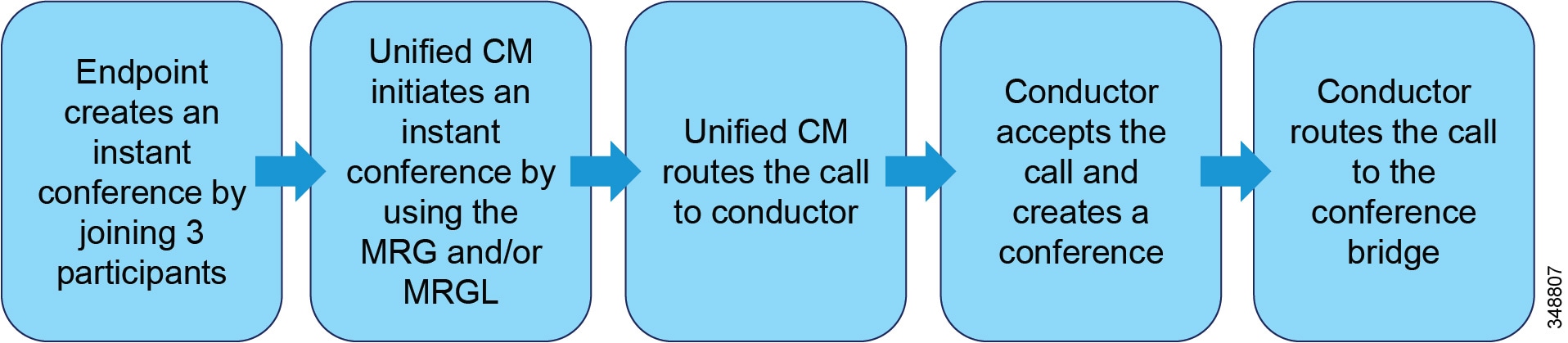
Figure 11-13 Flow of an Permanent Conference Call with Unified CM
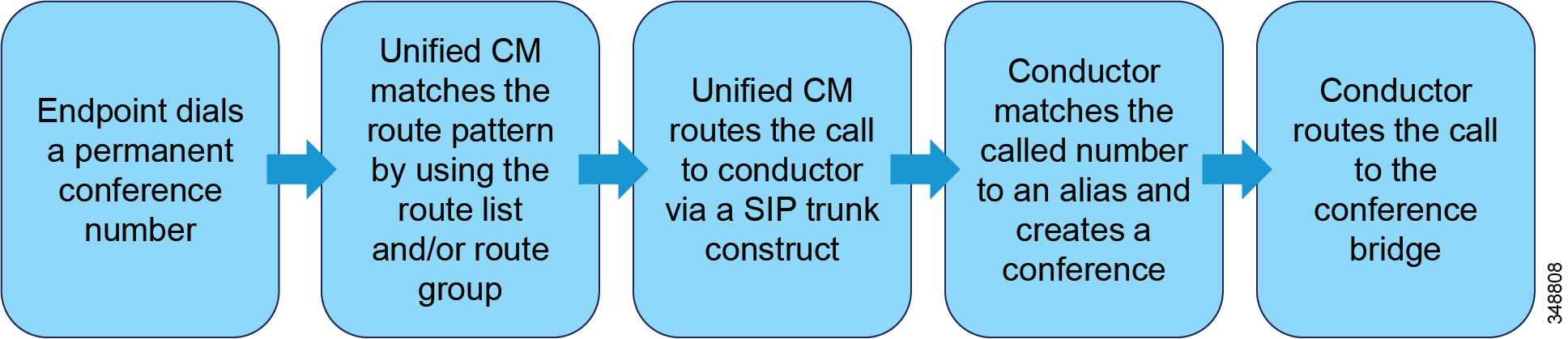
Once the steps in Figure 11-12 or Figure 11-13 are complete, the call is set up and media flows between the endpoint and the conference bridge.
In the case of MCU management, TelePresence Conductor can automatically cascade an active conference to a separate MCU to expand total capacity, and this is transparent to the users.
Because of its inherent high availability, Cisco TelePresence Conductor is well suited for organizations where video conferencing resiliency has a premium value and organizations with a large number of multipoint control units.
High Availability for Cisco Rich Media Conferencing
Proper design of the Cisco Rich Media Conferencing infrastructure requires building a robust and redundant solution from the bottom up. By structuring the solution with redundancy (redundant media resources groups, redundant route groups, Cisco TelePresence Conductor, and redundant media resources), you can build a highly available, fault tolerant, and redundant solution. The following sections provide design guidance for high availability:
- Media Resource Groups and Lists
- Route List and Route Groups
- Cisco VCS Conferencing Redundancy
- Redundancy with Cisco TelePresence Conductor
Media Resource Groups and Lists
When a user of a Cisco Collaboration endpoint that uses Cisco Unified CM as its call control activates the Conf, Join, or MeetMe softkey, Unified CM uses the Media Resource Manager to select conference bridges. Conference bridges or MCU resources are configured in the media resource groups (MRGs). The media resource group lists (MRGLs) specify a prioritized list of MRGs and can be associated with the endpoints. The Media Resource Manager uses MRGLs of the endpoints for selecting the conference bridge. How you group the resources is completely at your discretion, but Cisco recommends grouping the resources by using a logical modeling of the geographical placement whenever possible so that all endpoints at a given site use the conference bridges closest to them.
Cisco Unified CM has the Intelligent Bridge Selection feature, which provides a method for selecting conference resources based on the capabilities of the endpoints in the conference. If there are two or more video endpoints when the conference is initiated and a videoconferencing resource is available, Intelligent Bridge Selection chooses that resource for the conference. On the other hand, if no videoconferencing resource is available or if there are no video-capable endpoints in the conference, Intelligent Bridge Selection chooses an available audio resource for the conference. Intelligent Bridge Selection provides an added functionality to select secure conference bridges for secure conferences. However, secure conference bridge selection is dependent on device capabilities. Unified CM may decide to allocate secure conference bridges in lieu of video or audio conference bridges. Flexibility to change the behavior of the Intelligent Bridge Selection functionality is provided through service parameter configurations in Unified CM.
Intelligent Bridge Selection has the following advantages over other methods of conference bridge selection:
- Conference bridge selection by conference type - either secure, video, or audio conferences
- Simplified media resource configuration
- Optimized use of MCU video ports that potentially would have been used for audio-only conferences with other methods of bridge selection
All the conference bridge resources and MCUs can be in one MRGL, and Intelligent Bridge Selection will then select the conference bridge based on the need to do just an audio conference or a video conference.
Unified CM also supports an alternate way of selecting conference bridges, which can be specified by service parameter configurations. In this mode, Unified CM applies the following criteria to select the conference bridge resource to use, in the order listed here:
1.![]() The priority order in which the media resource groups (MRGs) are listed in the media resource group list (MRGL)
The priority order in which the media resource groups (MRGs) are listed in the media resource group list (MRGL)
2.![]() Within the selected MRG, the resource that has been used the least
Within the selected MRG, the resource that has been used the least
If the MCU is placed at the top of the MRGL for the phone, the MCU will always be chosen even for audio-only conferences that do not involve any video-capable participants. In this scenario, the MCU resources might be wasted on audio-only conferences and not be available to satisfy the request for a video conference when it occurs. This mode, however, is not recommended because it removes the intelligence from Unified CM to select the right resource on every conference made and should be used only by administrators who are aware of the system-wide effects of this service parameter setting.
For further information about media resource design, see the chapter on Media Resources.
Note![]() MeetMe conferences do not use the Intelligent Bridge Selection feature.
MeetMe conferences do not use the Intelligent Bridge Selection feature.
Route List and Route Groups
Route lists and route groups are common call routing mechanisms of reliability for calls that leave the Cisco Unified CM domain. For media resources integrated with Cisco Unified CM as a trunk, route lists and route groups should be used to achieve high availability if backup multipoint control units (MCUs) exist. Call admission control can be preserved by setting the locations of the media resources based on the trunk being used for the call.
To learn more about Route List and Route Group resiliency mechanisms, see the chapter on Dial Plan.
Cisco VCS Conferencing Redundancy
To provide redundancy for multipoint conferencing in Cisco VCS, Cisco recommends the use of Cisco TelePresence Conductor to provide the best redundancy available (see Redundancy with Cisco TelePresence Conductor). Alternate redundancy is also possible by using overlapping search rules. The search rule targeting the first choice should have a high priority, while rules targeting backup multipoint resources or secondary targets should be assigned a lower priority, thereby providing backup resources when the primary resource is unavailable. For further information about search rules in Cisco VCS, see the chapter on Dial Plan.
Redundancy with Cisco TelePresence Conductor
The Cisco TelePresence Conductor has the ability to be resilient in several ways:
- Within the pool configuration
- With the service preference
- With clustering of Conductors
- At the integration points with call control devices
The TelePresence Conductor has the ability to manage conferencing resources such as the TelePresence Server and TelePresence MCUs. Within its configuration it has the ability to group those resources into pools. These pools of conferencing resources contain similar types of devices: TelePresence MCUs must be in a pool with other TelePresence MCUs only, and TelePresence Servers must be in a pool with other TelePresence Servers. In addition, it is best practice to try to differentiate the MCUs by HD or SD to allow for more granularity of the video services. This granularity will allow the administrative staff to assign endpoints such as the Cisco Unified IP Phone 9971 and the Cisco TelePresence System EX20 to the SD resources while making the HD resources available for the high definition endpoints such as the Cisco TelePresence System MX, EX, and C Series devices. In addition, all Cisco TelePresence System (CTS) and TX Series endpoints can be directed by the Conductor to use the TelePresence Server, which supports ActivePresence and TIP, to maintain the immersive experience for all participants.
The ability to group conferencing resources by pools enables the Conductor to add redundancy at the pool level. Pool-level redundancy is achieved by having more than one device of a given type in the pool. The Conductor chooses between the multiple devices in a round-robin fashion by evaluating the number of conference ports being used at the time of conference setup. The conferencing device using the least number of ports will be chosen.
In addition, the Conductor has the ability to create an ordered list of pools, which is called a service preference. It is similar to a route list or media resource group list in Unified CM. At this level of configuration, the Conductor can use primary and secondary pools to create a redundant model of conferencing resources. For example, if the service preference has a list of MCU pools in this order: Pool 1 for the US and Pool 2 for EMEA (see Figure 11-14), then the Conductor will use all the resources in the US pool of devices first and, if needed, it can make a cascaded link between the MCU in Pool 1 and the MCU in Pool 2. The Conductor does this automatically as a part of its intelligent conferencing selection process.
Figure 11-14 Example of Service Preference Device Pools

The TelePresence Conductor can also be configured to use multiple Conductors for redundancy at the system level. This is achieved by clustering together multiple Conductors. A maximum of three TelePresence Conductors can be used in a clustered design. Cisco recommends at least two Conductors in all designs to ensure high availability of all the conferencing resources.
Clustering Conductors requires a low-latency connection with less than 30 ms round trip between the Conductor nodes. During the clustering process, the Conductors performs a database synchronization of all table entries, such as aliases, templates, service preferences, pools, and present state table of the conference resource ports. The initial clustering process has to have a primary Conductor that is used as the initial database for the cluster. Once the initial process is done, any Conductor in the cluster can update the database that is synchronized across all the Conductor nodes.
For more details on clustering, refer to the Cisco TelePresence Conductor deployment guides available at
http://www.cisco.com/en/US/products/ps11775/products_installation_and_configuration_guides_list.html
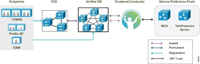
The Conductor can integrate with the Video Communications Server (VCS) and Unified CM in either a standalone or clustered scenario. In a clustered scenario this integration is different for the two call control devices, and a single Conductor or clustered Conductor cannot integrate into both call control devices at the same time. Cisco recommends setting up a SIP trunk between VCS and Unified CM, with the Conductor or Conductor cluster integrated with Unified CM as shown in Figure 11-15.
Figure 11-15 TelePresence Conductor Integrated with Unified CM and VCS
When VCS is the primary call control integration point for the Conductor cluster, redundancy is achieved by adding the individual IP addresses of each Conductor cluster node, or the fully qualified domain name (FQDN) of each Conductor cluster node, or the FQDN of the Conductor cluster with round-robin DNS. These settings are configured under the policy services page of the VCS. For more details on clustering, refer to the Cisco TelePresence Conductor deployment guides available at
http://www.cisco.com/en/US/products/ps11775/products_installation_and_configuration_guides_list.html
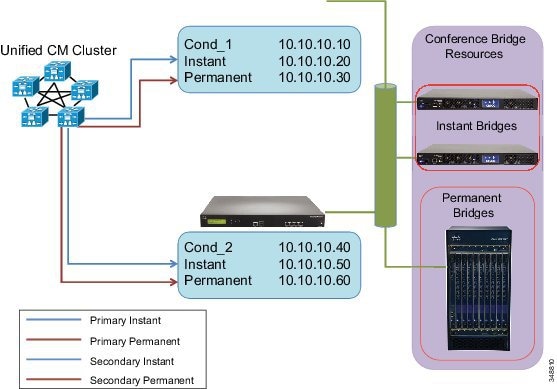
When Unified CM is the primary call control integration point for the Conductor cluster, redundancy is achieved by having multiple connections to Unified CM for the instant and permanent conference calls. When the Conductor is clustered in this design, it requires unique virtual IP addresses that are the termination points for the Unified CM conference bridge and SIP trunk. Because the virtual IP addresses are unique on each Conductor cluster node, this information cannot be replicated in the database synchronization process and needs to be configured by the administrator. Once this configuration is complete, Cisco recommends using different Conductor cluster nodes for the primary, secondary, or tertiary links to Unified CM.
For example, as illustrated in Figure 11-16, a Unified CM should be configured to use the virtual IP address of Conductor_1's instant conference configuration as the primary connection, and the secondary connection is set to the virtual IP address of the instant conference configuration on Conductor_2. For the permanent calls, the destination address of the primary SIP trunk should be Conductor_2's virtual IP address for the permanent conference configuration, and the secondary connection is set to the virtual IP address of the permanent conference configuration on Conductor_1.
Figure 11-16 Conferencing Redundancy with Unified CM Call Control
Note![]() Additional redundancy can be achieved within Unified CM for instant and permanent conference calls. For more information, refer to the sections on Media Resource Groups and Lists, and Route List and Route Groups.
Additional redundancy can be achieved within Unified CM for instant and permanent conference calls. For more information, refer to the sections on Media Resource Groups and Lists, and Route List and Route Groups.
Capacity Planning for Cisco Rich Media Conferencing
Capacity planning is critical for successful rich media conferencing deployments. Given the many features and functions provided by Cisco Rich Media Conferencing services as well as the many different types of media resources used as part of the architecture, it important to size the rich media conferencing infrastructure and its individual components to ensure they meet the capacity needs of a particular deployment.
This section provides information and best practices for sizing the media resources used in the Cisco Rich Media Conferencing architecture.
Sizing the Conferencing Resources
There are several factors involved in determining the types and number of conferences that a conference bridge can support. These sizing factors are different for different models of conference bridges. MCUs can also make available more ports when using standard definition (SD) mode as compared to the high definition (HD) mode, while voice conference bridges use less DSP processing when low-complexity codecs are used.
Calculating the size of conference resources depends on the following factors:
- The type of codec and resolution for the video conference
- The total number of ports that the MCU can support, or the number of DSPs the conference bridge can support
- The number of ports that the MCU can dedicate to each protocol
- Whether cascading conferences are needed between MCUs
For specific information about the number of ports or DSPs (in the case of voice conference bridges) supported, refer to the product documentation for your conference bridge hardware, available on http://www.cisco.com. Due to the almost infinite number of possible variations, it is not feasible to provide capacity numbers within this document for every scenario. Many Cisco Rich Media Conferencing deployments may use a mixture of SIP or SCCP instant conferences, H.323 and SIP reservationless conferences, and H.323 and SIP scheduled conferences. The conferencing resources must be sized to accommodate all of those types of conferences at the correct speeds and video layouts. Needless to say, this can become quite complex to determine, so Cisco has developed calculator tools to assist in sizing the conferencing resources. For sizing PVDM hardware, use the DSP Calculator available at
http://www.cisco.com/web/applicat/dsprecal/dsp_calc.html
Note![]() Consult with your Cisco sales representative for assistance on sizing the conferencing resources for your particular environment.
Consult with your Cisco sales representative for assistance on sizing the conferencing resources for your particular environment.
Resource Allocation and Allocation Logic
A critical part of the Cisco Rich Media Conferencing design is to allocate the correct resources in the right place. However, to do this you first need to understand how the allocation logic works to allocate the right amount of resources in the corresponding location. Resource allocation also works differently in different call control applications.
The following information applies to conferences that are initiated or processed by endpoints controlled by Cisco Unified CM:
- If an instant conference that does not use the MultiSite or built-in bridge functionality is initiated by an endpoint registered to Unified CM, the resource is allocated based on the media resource group and list assigned to the conference initiator. All other endpoints in the conference just join their streams to the resource selected by the conference initiator. (See Figure 11-17.)
- If a MeetMe video or audio conference is initiated by an endpoint registered to Unified CM, the resource is allocated based on the media resource group and list assigned to the conference initiator. All other endpoints in the conference just join their streams to the resource selected by the conference initiator. (See Figure 11-17.)
- If a permanent video conference is created, the conference call (all participants' individual calls) will be processed based on the dial plan applicable to the call (permanent alias or number dialed) and off-loaded to the applicable trunk multipoint device.
- If a scheduled conference is create, the conference call (all participants' individual calls) will be processed based on the dial plan applicable to the call and off-loaded to the applicable trunk multipoint device.
- The resource allocation logic for scheduled conferencing lies in the scheduling platform resource selection algorithm.
In Figure 11-17, assume that the conference was initiated by endpoint A, which has its local resource as the first option in the media resource group list. Note how, for this particular conferencing example, the usage of the local resource is bandwidth intensive because there are more remote users than local participated in the conference, thus causing the remote users’ streams to traverse the WAN.
Figure 11-17 Conference Initiated by Endpoint A
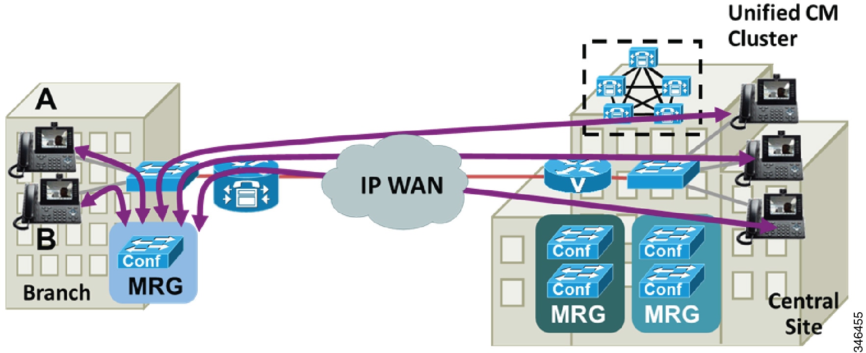
The following information applies to conferences that are initiated or processed by endpoints controlled by Cisco VCS:
- If an instant Multiway TM conference is created, the resource is selected based on the applicable selected search rule (the MCU automatically creates the conference once it detects the unknown conference number). All other participants' media streams are joined to the resource selected by the conference initiator.
- If a permanent or scheduled conference is created, the call is processed based on the applicable search rules.
- The resource allocation logic for scheduled conferencing lies in the scheduling platform resource selection algorithm.
For further information about the processing of media resources groups and lists, refer to the section on Media Resource Groups and Lists, and the chapter on Media Resources.
Scalability
Cisco recommends following the guidelines in this section to scale the design of your Cisco Rich Media Conferencing deployment.
Media Resource Groups and Lists
Make use of media resource groups and lists whenever possible to achieve the desired scalability for instant and MeetMe conferences in a Cisco Unified CM deployment. For example, see Figure 11-18, where two of MCUs are used to double the instant video conferencing capacity of Device Pool 2 by adding the two containing media resource groups into the media resource group list used by the pool. For more information on media resource groups and lists, see the chapter on Media Resources.
Figure 11-18 Example of Media Resource Groups and Lists
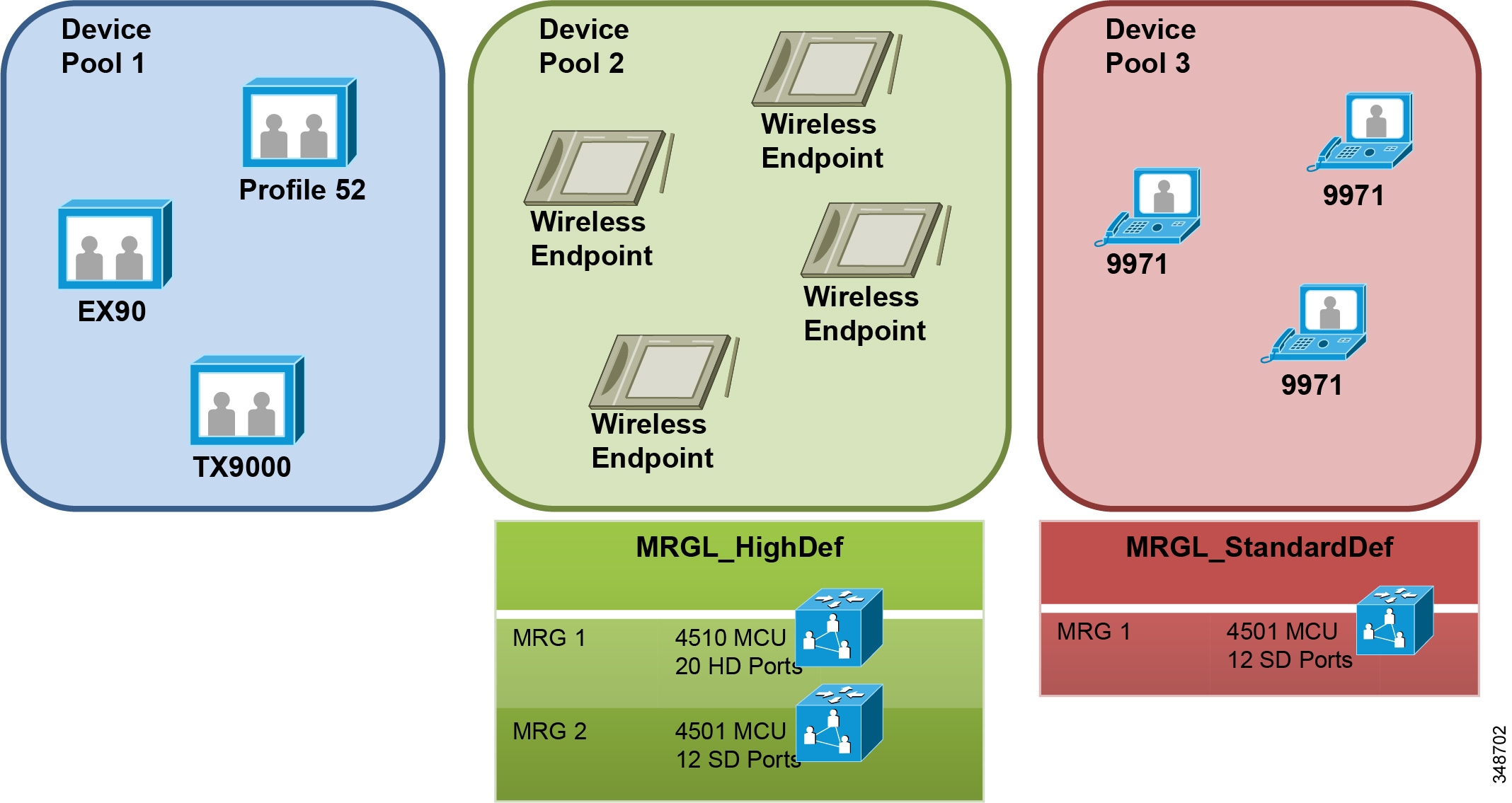
Scaling Video Conferencing with TelePresence Conductor
Make use of Cisco TelePresence Conductor to scale video conferencing services. TelePresence Conductor offers orchestration for multiple resources so that they can be allocated as needed, and it can span conferences through more than one multipoint resource when its capacity is exceeded. Figure 11-19 depicts an example of how a single Conductor server can improve the scalability of a deployment for instant video conferencing. In this example the resource allocation starts when the user (1) initiates a conference on Cisco Unified CM. This in turn sends the request (2) to the Conductor (3). The Conductor determines which is the most available resource to be utilized and creates the conference in the MCU (4). It then replies to Unified CM with the conference details (5), and Unified CM starts the conference signaling negotiations with the MCU (6). The media (RTP) flows point-to-point (directly) between the endpoint(s) and the MCU. TelePresence Conductor pools the resources, thus making all those collective resource available to Unified CM as if they were a single resource.
Figure 11-19 Example of Cisco TelePresence Conductor Allocating Conference Resources
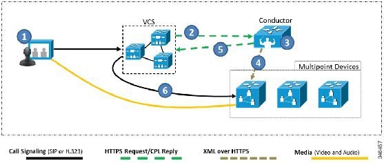
For further information about Cisco TelePresence Conductor, see the section on Redundancy with Cisco TelePresence Conductor. The information and logic documented in that section also apply to increasing the scalability in a deployment.
Make use of clustering and/or cascading if your multipoint device supports it. (For the definition and functionality of cascading, see the section on Cascading.) Clustering multipoint blades in a Cisco TelePresence MSE 8000 series chassis has resource implications because it can triple or quadruple the amount of bandwidth that is required for that chassis. On the other hand, although cascading can be used to increase conference capacity while maintaining a distributed multipoint deployment, note that cascading can create an inconsistent meeting experience. Cascading is better automated by Cisco TelePresence Conductor.
Table 11-7 summarizes information about which multipoint devices are capable clustering or cascading.
|
|
|
|
|---|---|---|
Yes2 |
|
1.Requires Cisco TelePresence Server MSE 8710, MCU 5300 Series, or MCU MSE 8510 blades in an MSE 8000 Series chassis. 2. The MCU 5300 can be.configured for clustering when configured in a stack. |
Design Considerations for Cisco Rich Media Conferencing
This section provides general guidance and recommendations for Cisco Rich Media Conferencing design.
Cisco Rich Media Conferencing Deployment Models
This section provides general information about the various Cisco Rich Media Conferencing deployment models. It also examines where and when each Cisco Rich Media Conferencing deployment model is most effective and best used.
Cisco Hosted Solutions
Cisco Collaboration Meeting Rooms (CMR) Cloud is a Cisco Rich Media Conferencing deployment model delivered through the cloud. Cisco CMR Cloud is a video collaboration service. It couples WebEx Personal Rooms and the cloud-based WebEx Video Bridge into one, always-available meeting experience. CMR Cloud is accessible from any standards-based video device. It provides simple, highly secure collaboration from the scalable Cisco WebEx Cloud. The cloud service is designed to help users make connections across their business community. All the call control and multipoint units reside in the cloud.
For a conference to occur, the stream of every single participant’s endpoint must traverse the Internet; therefore, sizing of the correct Internet links is crucial for an optimal experience. Cisco CMR Cloud is geared to mid-size deployments. For more information about Cisco CMR Cloud, refer to the documentation available at
http://www.cisco.com/c/en/us/products/conferencing/collaboration-meeting-rooms-cmr-cloud/index.html
Multiple Sites with Centralized Resources
Centralized designs are recommended for voice and video deployments with few collaboration endpoints, and for larger deployments that extend over a limited geographical area.
For centralized deployments, Cisco recommends locating the multipoint device at a regional or headquarters campus site with the necessary WAN bandwidth available to each of the remote sites, as well as the necessary LAN bandwidth within the campus. In addition, the multipoint device should be centrally located, based on the geographical location of the endpoints, to prevent unnecessary latency caused by back-hauling calls to a site at the far edge of the network, although this might not be entirely possible due to the existing network layout.
Figure 11-20 depicts an example deployment of centralized resources with video endpoints located in Dallas, London, and San Jose. In this example the New York location was chosen as the geographically central location for the multipoint device, thus providing the least latency to the video users.
Figure 11-20 Multiple Sites with Centralized Resources

Multiple Sites with Distributed Resources
Cisco recommends a distributed configuration for large voice and video deployments spread across separate geographical regions. As the collaboration network grows, it is very advantageous to distribute multipoint devices to minimize latency and save bandwidth across expensive WAN links.
The Cisco TelePresence Server and MCU appliances (Cisco TelePresence Server 7010 and Cisco TelePresence MCU 4200, 4500, and 5300 Series) are suited for organizations moving from a centralized to a distributed deployment. As the collaboration network usage grows further, these deployments can evolve their standalone multipoint devices to chassis-based blades (Cisco TelePresence Server MSE 8710 and Cisco TelePresence MCU MSE 8420 and MSE 8510) for increased scale and redundancy.
Figure 11-21 shows a distributed deployment with a multipoint device in New York providing multipoint services for North America, and a multipoint device in Paris providing multipoint services for Europe.
Figure 11-21 Multiple Sites with Distributed Resources

Design Recommendations
This section provides general recommendations for Cisco Rich Media Conferencing deployments.
Latency
For an optimal and natural experience regardless of deployment model, multipoint devices should be located at sites with one-way network latency of less than 150 ms between the multipoint device and any endpoints, provisioned with adequate port capacity and provided with ample bandwidth for the number of provisioned conferencing ports. Bandwidth requirements vary depending on the required maximum call rate of endpoints and the number of endpoints connecting to the multipoint device. Provision based on the maximum bandwidth that a particular endpoint requires for the desired call rate and resolution. For details, refer to the specific endpoints' data sheets available on http://www.cisco.com.
Cascading
Cascading refers to the ability to bridge together conferences on two multipoint devices as one conference. This increases the maximum number of endpoints supported in a conference and can reduce bandwidth across links, depending on how the multipoint devices are deployed. Note that cascading conferences can create an inconsistent user experience, especially when features such as continuous presence are used by the endpoints. This is due to the remote conference appearing as just another endpoint on the local conference.
When making use of cascading for a large briefing conference type, it is a best practice to have all slave MCUs set to full-screen voice switched, and the master MCU set to the desired Continuous Presence layout. All the main speakers should be located in the master MCU so that they can be provided with the best experience.
MTP Used with a Conference Bridge
Media termination points (MTPs) are used in a conference call when one or more participant devices in the conference use RFC 2833 signaling format. When the conference feature is invoked, Unified CM allocates MTP resources for every conference participant device in the call that supports only RFC 2833. This is regardless of the DTMF capabilities of the conference bridge used.
Video Transcoding and Video Switching
It is important to understand that video conference bridges accomplish their conferencing functionality by doing media transcoding or media switching. This transcoding or switching is perceived by the video conferencing users as the mixing of the media streams. Organizations looking to deploy a multipoint conferencing solution must understand the differences between transcoding and switching architectures because both architectures provide advantages that should be considered (see Table 11-8 ):
- Transcoding involves specialized video hardware, allowing the incoming video to be decoded and then re-encoded before being sent on.
- Switching does not require specialized video hardware but uses software instead. The incoming video and audio streams are copied and redirected to the correct endpoints.
|
|
|
|
|---|---|---|
 Feedback