- What’s New in This Chapter
- Call Processing Architecture
- High Availability for Call Processing
- Capacity Planning for Call Processing
- Design Considerations for Call Processing
- Computer Telephony Integration (CTI)
- Integration of Multiple Call Processing Agents
Call Processing
Revised: January 15, 2015; OL-30952-03
The handling and processing of voice and video calls is a critical function provided by IP telephony systems. This functionality is handled by some type of call processing entity or agent. Given the critical nature of call processing operations, it is important to design unified communications deployments to ensure that call processing systems are scalable enough to handle the required number of users and devices and are resilient enough to handle various network and application outages or failures.
This chapter provides guidance for designing scalable and resilient call processing systems with Cisco call processing products. These products include Cisco Unified Communications Manager (Unified CM), Cisco Unified Communications Manager Express (Unified CME), and Cisco TelePresence Video Communication Server (VCS). The discussions focus predominately on the following factors:
- Scale — The number of users, locations, gateways, applications, and so forth
- Performance — The call rate
- Resilience — The amount of redundancy
Specifically, this chapter focuses on the following topics:
This section discusses general call processing architecture and the various call processing hardware options. This section also provides information on Unified CM clustering and Cisco TelePresence VCS clustering.
This section examines high availability considerations for call processing, including network redundancy, server redundancy, and load-balancing.
This section provides an overview of sizing for call processing deployments.
This section provides a summarized list of high-level design guidelines and best practices for deploying call processing.
This section explains the Cisco Computer Telephony Integration (CTI) architecture and discusses CTI components and interfaces, CTI functionality, and CTI provisioning and capacity planning.
This section discusses the integration of multiple call processing agents, which is typically done with Cisco Unified CM Session Management Edition (SME). It also covers direct integration of Cisco Unified CM with Cisco Unified Communications Manager Express (Unified CME) and integration of Cisco Unified CM with Cisco TelePresence Video Communication Server (VCS).
What’s New in This Chapter
Table 9-1 lists the topics that are new in this chapter or that have changed significantly from previous releases of this document.
Call Processing Architecture
In order to design and deploy a successful Unified Communications system, it is critical to understand the underlying call processing architecture that provides call routing functionality. This functionality is provided by the following Cisco call processing agents:
Cisco Unified CM provides call processing services for small to very large single-site deployments, multi-site centralized call processing deployments, and/or multi-site distributed call processing deployments. Unified CM is at the core of a Cisco Collaboration solution, and it serves as a foundation to deliver voice, video, TelePresence, IM and presence, messaging, mobility, web conferencing, and security.
Access to the enterprise collaboration network and to Unified CM from the internet to enable remote access and business-to-business secure telepresence and video communications, is also available through different collaboration edge solutions such as VPN and Cisco Expressway.
Cisco Business Edition 6000 and Cisco Business Edition 7000 are packaged Collaboration solutions that include services such as call processing, messaging, conferencing, and contact center. Those services are provided by deploying multiple co-resident Cisco Collaboration applications running as separate virtual machines that leverage VMware vSphere Hypervisor. Call processing services are offered though Cisco Unified Communications Manager (Unified CM) and/or Cisco TelePresence Video Communication Server (VCS). One of the benefits of Cisco Business Edition includes the ease of deploying a Cisco Collaboration solution with, for example, the virtualization hypervisor being pre-installed on the hardware platform and the collaboration applications software being preloaded and/or pre-installed. Cisco Business Edition 6000S is targeted for deployment with up to 150 users and 300 devices. Cisco Business Edition 6000M and Cisco Business Edition 6000H are targeted for deployments with up to 1,000 users. Cisco Business Edition 7000 is targeted for deployments with more than 1,000 users. The design and sizing of the Cisco Collaboration applications have been simplified with Cisco Business Edition 6000. With Cisco Business Edition 7000, however, normal Unified CM design and sizing guidance apply.
Cisco TelePresence VCS is a video application that provides video endpoint registration, call processing, and bandwidth management for SIP and H.323 endpoints. VCS acts as a SIP registrar, a SIP proxy server, an H.323 gatekeeper, and a SIP-to-H.323 gateway server to provide interworking between SIP and H.323 devices. Cisco TelePresence VCS also provides external communications using NAT/firewall traversal when combined with the VCS Expressway.
Cisco recommends deploying Unified CM as the main call processing agent for all endpoints, including TelePresence endpoints and room-based TelePresence conferencing systems that support SIP, and use VCS only for full-featured interoperability with H.323 telepresence endpoints or integration with third-party video endpoints. This is to avoid the dial plan and call admission control complexities that dual call control introduces.
Cisco Unified CME provides call processing services for small single-site deployments, larger distributed multi-site deployments, and deployments in which a local call processing entity at a remote site is needed to provide backup capabilities for a centralized call processing deployment of Cisco Unified CM.
Call Processing Virtualization
Virtualization with Cisco Collaboration allows deployments to run one or multiple Cisco Collaboration application instances as virtual machines on the same physical server through an hypervisor. This has obvious benefits over traditional deployments where the applications are directly running on the hardware platform. For example, costs (such as server, electricity, cooling, and rack space costs) can be reduced significantly, and the operation and maintenance of the hardware platforms can be simplified.
The hypervisor that is required with Cisco Collaboration is the VMware ESXi Hypervisor. The Cisco Collaboration applications running as virtual machines are referred as guests, and the hardware platform or physical server where the virtual machines are running is referred as a host.
Each virtual machine has associated virtual hardware resources such as virtual CPU, virtual memory, and virtual disk. Those resources are defined for each Collaboration application in predefined templates that are distributed through an Open Virtualization Archive (OVA), an open standards-based method for packaging and distributing virtual machine templates. For many of the Cisco Collaboration applications, different OVA template sizes are available in order to provide different capacities. OVA templates must be used when installing a Cisco Collaboration application, not only to define the correct virtual hardware resources but also to ensure that the virtual disks are not misaligned with the host physical disks, which would impact the storage performance.
The virtualization support for the Cisco Collaboration call processing agents is as follows:
- Cisco Unified CM runs only as a virtual application; it cannot be deployed directly on a Cisco MCS or UCS server, for example.
- Cisco TelePresence VCS can be deployed directly on a physical appliance or by using virtualization.
- Cisco Unified CME runs within the Cisco IOS software and does not support virtualization.
For more information on the considerations for designing and deploying virtualization of Cisco Unified Communications applications, refer to the information available at
Call Processing Hardware
In general, Cisco Collaboration applications are deployed using virtualization, and two hardware configuration options are available with virtualization:
TRCs are selected hardware configurations based on the Cisco Unified Computing System (UCS) servers. They include all the hardware platforms for Cisco Business Edition 6000 and 7000. They have a fixed hardware configuration and they are tested for specific guaranteed performance, capacity, and application co-residency scenarios. They are intended for customers who want a pre-engineered packaged solution with performance guarantee and/or customers who are not necessarily experienced with virtualization.
The hardware configuration for each TRC is well defined, and allowed deviation from this hardware configuration is very limited. For example, changing the CPU model or number of cores, or changing the RAID configuration of a TRC, would change the server qualification, and the server would not be considered as a TRC anymore but rather as specifications-based hardware.
Cisco Business Edition 6000 is available with three hardware platform options: BE6000S (based on UCS E-series platform), BE6000M, and BE6000H. Cisco Business Edition 7000 is available with two hardware platforms: BE7000M and BE7000H.
For more details on the TRC and Cisco Business Edition hardware platforms, refer to the documentation at http://www.cisco.com/go/uc-virtualized.
Specifications-based hardware (sometimes simply referred as "specs-based") provides more flexible hardware configurations. For example, it allows you to select a platform based on a Cisco UCS TRC and to change the CPU model, number of cores, and RAID configuration, and/or to use an iSCSI or NAS storage. If desired, it also allows you to use a server vendor other than Cisco. Any specifications-based hardware server, whether it is Cisco or not, must be listed in the following VMware Compatibility Guide :
http://www.vmware.com/resources/compatibility/search.php
While specification-based hardware provides more flexible hardware configurations, some requirements must still be met. For example, there are requirements around the CPU model and minimum CPU speed, and vCenter is required in order to collect logs and statistics. With specifications-based hardware, it is important to understand that the hardware configuration has not been explicitly validated by Cisco with Cisco Collaboration applications. Therefore hardware compatibility cannot be guaranteed, and performance of the Cisco Collaboration applications cannot be predicted or assured. To obtain guidance on the performance of Cisco Collaboration applications with specifications-based hardware, use the TRCs or Cisco Business Edition 6000 and 7000 hardware platforms as references. For more information, refer to the documentation at http://www.cisco.com/go/uc-virtualized.
The following section covers the hardware platforms specific to the Cisco call processing agents:
- Cisco Unified CM runs only as a virtualized application using the VMware Hypervisor. It does not run directly on a server without the VMware Hypervisor. Both virtualization hardware platform options are supported: Tested Reference Configurations (TRCs) and specifications-based hardware. For more information on using a virtualized platform with Unified CM, refer to the latest version of Cisco Unified Communications Manager on virtualized servers, available at
http://www.cisco.com/en/US/products/sw/voicesw/ps556/prod_installation_guides_list.html
- Cisco TelePresence Video Communication Server (VCS) runs either directly on a physical appliance or as a virtualized application on VMware. When virtualized, similarly to Unified CM, Cisco VCS supports both TRCs and specifications-based hardware. For more information on running Cisco VCS as a virtualized application, refer to the Cisco TelePresence Video Communication Server Virtual Machine Deployment Guide, available at
http://www.cisco.com/en/US/products/ps11337/products_installation_and_configuration_guides_list.html
- Cisco Unified CME runs on Cisco Integrated Services Routers (ISR) such as the Cisco 2900, 3900, or 4000 Series ISRs. Cisco Unified CME does not run as a virtual application.
Determining the appropriate call processing type and platform for a particular deployment will depend on the scale, performance, and redundancy required. In general, Unified CM provides more capacity and higher availability, while Cisco Unified CME and Cisco Business Edition 6000 provide lower levels of capacity and redundancy. For specifics regarding redundancy and scalability, see the sections on High Availability for Call Processing, and Capacity Planning for Call Processing.
Unified CM Cluster Services
While Cisco Unified CME is a standalone call processing application, Unified CM supports the concept of clustering. The Unified CM architecture enables a group of server nodes to work together as a single call processing entity or IP PBX system. This grouping of server nodes is known as a cluster. A cluster of Unified CM server nodes may be distributed across an IP network, within design limitations, allowing for spatial redundancy and, hence, resilience to be designed into the Unified Communications System.
Within a Unified CM cluster, there are server nodes that provide unique services. Each of these services can coexist with others on the same server node. For example, in a small system it is possible to have a single server node providing database services, call processing services, and media resource services. As the scale and performance requirements of the cluster increase, many of these services should be moved to dedicated server nodes.
The following section describes the various functions performed by the server nodes that form a Unified CM cluster, and it provides guidelines for deploying the server nodes in ways that achieve the desired scale, performance, and resilience.
Cluster Server Nodes
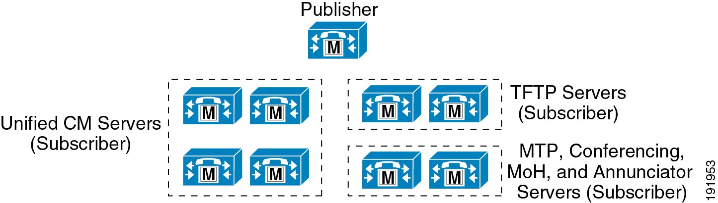
Figure 9-1 illustrates a typical Unified CM cluster consisting of multiple server nodes. There are two types of Unified CM server nodes, publisher and subscriber. These terms are used to define the database relationship during installation.
Figure 9-1 Typical Unified CM Cluster
Publisher
The publisher is a required server node in all clusters, and as shown in Figure 9-1, there can be only one publisher per cluster. This server node is the first to be installed and provides the database services to all other subscribers in the cluster. The publisher node is the only server node that has full read and write access to the configuration database.
On larger systems with more than 1250 users, Cisco recommends a dedicated publisher to prevent administrative operations from affecting the telephony services. A dedicated publisher does not provide call processing or TFTP services running on the node. Instead, other subscriber nodes within the cluster provide these services.
The choice of OVA template for the publisher should be based on the desired scale and performance of the cluster. Cisco recommends that the publisher have the same server node performance capability as the call processing subscribers.
Subscriber
When the software is installed initially, only the database and network services are enabled. All subscriber nodes subscribe to the publisher to obtain a copy of the database information. However, in order to reduce initialization time for the Unified CM cluster, all subscriber nodes in the cluster attempt to use their local copy of the database when initializing. This reduces the overall initialization time for a Unified CM cluster. All subscriber nodes rely on change notification from the publisher or other subscriber nodes in order to keep their local copy of the database updated.
As shown in Figure 9-1, multiple subscriber nodes can be members of the same cluster. Subscriber nodes include Unified CM call processing subscriber nodes, TFTP subscriber nodes, and media resource subscriber nodes that provide functions such as conferencing and music on hold (MoH).
Call Processing Subscriber
A call processing subscriber is a server node that has the Cisco CallManager Service enabled. Once this service is enabled, the node is able to perform call processing functions. Devices such as phones, gateways, and media resources can register and make calls only to servers with this service enabled. As shown in Figure 9-1, multiple call processing subscribers can be members of the same cluster. In fact, Unified CM supports up to eight call processing subscriber nodes per cluster.
TFTP Subscriber
A TFTP subscriber or server node performs two main functions as part of the Unified CM cluster:
- The serving of files for services, including configuration files for devices such as phones and gateways, binary files for the upgrade of phones as well as some gateways, and various security files
- Generation of configuration and security files, which are usually signed and in some cases encrypted before being available for download
The Cisco TFTP service that provides this functionality can be enabled on any server node in the cluster. However, in a cluster with more than 1250 users, other services might be impacted by configuration changes that can cause the TFTP service to regenerate configuration files. Therefore, Cisco recommends that you dedicate a specific subscriber node to the TFTP service, as shown in Figure 9-1, for a cluster with more than 1250 users or any features that cause frequent configuration changes.
Cisco recommends that you use the same OVA template for the TFTP subscribers as used for the call processing subscribers.
Media Resource Subscriber
A media resource subscriber or server node provides media services such as conferencing and music on hold to endpoints and gateways. These types of media resource services are provided by the Cisco IP Voice Media Streaming Application service, which can be enabled on any server node in the cluster.
- Music on Hold (MoH) — Provides multicast or unicast music to devices that are placed on hold or temporary hold, transferred, or added to a conference. (See Music on Hold.)
- Annunciator service — Provides announcements in place of tones to indicate incorrectly dialed numbers or call routing unavailability. (See Annunciator.)
- Conference bridges — Provide software-based conferencing for instant and permanent conferences. (See Transcoding.)
- Media termination point (MTP) services — Provide features for H.323 clients, H.323 trunks, and Session Initiation Protocol (SIP) endpoints and trunks. (See Media Termination Point (MTP).)
Because of the additional processing and network requirements for media resource services, it is essential to follow all guidelines for running media resources within a cluster. Generally, Cisco recommends non-dedicated media resource subscribers for multicast MoH and annunciator services, but dedicated media resource subscribers as shown in Figure 9-1 are recommended for unicast MoH as well as large-scale software-based conferencing and MTPs unless those services are within the design guidelines detailed in the chapter on Media Resources.
Additional Cluster Services
In addition to the specific types of subscriber nodes within a Unified CM cluster, there are also other services that can be run on the Unified CM call processing subscriber nodes to provide additional functionality and enable additional features.
Computer Telephony Integration (CTI) Manager
The CTI Manager service acts as a broker between the Cisco CallManager service and TAPI or JTAPI integrated applications. This service is required in a cluster for any applications that utilize CTI. The CTI Manager service provides authentication of the CTI application and enables the application to monitor and/or control endpoint lines. CTI Manager can be enabled only on call processing subscribers, thus allowing for a maximum of eight nodes running the CTI Manager service in a cluster.
For more details on CTI Manager, see Computer Telephony Integration (CTI).
Various types of application services can be enabled on Unified CM, such as Cisco Unified CM Assistant, Extension Mobility, and Web Dialer. For detailed design guidance on these applications, see the chapter on Cisco Unified CM Applications. The Cisco IM and Presence service can also be added (see the chapter on Cisco Unified CM IM and Presence Service).
Mixing Unified CM OVA Templates
While Cisco recommends using the same OVA template for all Unified CM nodes in a cluster, mixing OVA templates within a cluster is allowed, provided that the Unified CM OVA templates designed and reserved for Cisco Hosted Collaboration Solution (HCS), such as the 2,500-user OVA template with a smaller vDisk (60 GB), are not used. Cisco also recommends that the OVA template used for the Unified CM publisher should not be smaller than any other Unified CM OVA template used in the same cluster and that the OVA template used for the backup subscribers should not be smaller than the OVA template used for the primary subscribers.
When mixing OVA templates within a cluster, differences in capacity between the various OVA templates must be considered because the overall cluster capacity might ultimately be dictated by the capacity of the node using the smallest OVA template within the cluster. For information on call processing capacity, see the section on Capacity Planning for Call Processing.
Mixing different types of hardware platforms within a cluster is also allowed, but because all OVA templates are not supported on all server hardware, this might result in mixing OVA templates and therefore might impact the overall cluster capacity. Mixing servers from different vendors is allowed, but this would be under the specifications-based hardware policy, and Unified CM performance is not guaranteed on this type of platform mix.
Cisco Prime License Manager
Cisco Collaboration Systems incorporate the Cisco Prime License Manager (Cisco Prime LM) that provides centralized license management. Customers purchase licenses and install them on the Cisco Prime LM application. The Cisco Prime LM application then collects requirements from all the applications, aggregates them, and compares them with the total available licenses.
The following Unified Communications applications use Cisco Prime LM:
- Cisco Unified Communications Manager (Unified CM) – including Cisco IM and Presence, which is licensed through Unified CM, and Cisco Unified Communications Manager Session Management Edition (Unified CM SME)
- Cisco Unity Connection
- Cisco Emergency Responder
When these applications are deployed as part of Cisco Business Edition 6000 or 7000, they also use Cisco Prime LM.
Following license purchase, the licenses are registered (through electronic fulfillment on Cisco Prime LM or manually at the Product License Registration portal at www.cisco.com/go/license), and then installed on Cisco Prime License Manager. Cisco Prime LM is connected to the application instances under license management, and it polls the applications. When polled, a subscribing application sends its license requirements to Prime LM, and Prime LM compares the application's requirements to the available licenses. If the application's requirements, totaled for all application instances, are within the available license count, then Prime LM returns a status of in compliance. Similarly, if license requirements exceed available licenses, then Prime LM returns a status of “not in compliance.”
An application is allowed 60 days of non-compliance during which administrators can make changes if there are insufficient licenses or if the Prime LM node has lost communication with the application node. After 60 days of non-compliance, the Unified Communications Manager application(s) will no longer allow administrative changes; however, the application(s) will continue to function (call control) with no loss of service. After 60 days of non-compliance, the Unity Connection application(s) will allow administrative changes, but the application(s) will not continue to function (users will not have access to voice messaging).
For more information on Cisco Unified Communications licensing, refer to the information at
Deployment Scenarios
Prime LM is installed automatically on the same virtual machine as the Unified CM (including SME) and Unity Connection applications when they are installed. You may choose to use Prime LM on one of these virtual machines in a co-resident configuration, as the active managing Prime LM, or you may opt to run Prime LM in a standalone configuration where Prime LM is installed on a dedicated virtual machine.
In the co-resident configuration, Prime LM consumes only a very small amount of resources and hence is considered to have no impact to the virtual machine sizing. For example, no additional vCPUs would need to be added to the virtual machine configuration because of the Prime LM service. In the co-resident configuration, Cisco Prime LM is supported for use on any of the applications’ OVA templates.
In a standalone configuration the Prime LM resides on a separate virtual machine created and managed specifically for, or dedicated to, the Prime LM application. In the standalone configuration, the Prime LM is installed as a separate virtual machine using the Prime LM OVA template.
The main considerations for choosing between co-resident and standalone deployments center around administration and management. The main benefits of deploying Prime LM in a standalone configuration are as follows:
- Upgrading a standalone Cisco Prime LM is done independently from upgrading the applications (Unified CM or Unity Connection). Whereas, upgrading a co-resident configuration of Cisco Prime LM is done by upgrading the co-resident application, which upgrades the application and Cisco Prime LM at the same time
- Platform changes to Unified Communications applications (Unified CM or Unity Connection) might require changes to a co-resident Prime LM application. For example, a change in the MAC address would require transferring the registration of the license file(s) for a co-resident Prime LM; however, in the case of standalone Prime LM, platform changes such a MAC address change of the application virtual machine would not require transferring the registration of the license file(s).
- Administrative changes required on a standalone Prime LM will not impact the application servers. For example, on a co-resident configuration, having to upgrade or reboot the Prime LM would require an upgrade or reboot of the application.
The trade-off, however, with a standalone configuration is that it requires a separate virtual machine to be created and managed.
Deployment Recommendations:
- If you are installing only a single application on a single node or cluster, run Prime LM co-resident.
- If you are installing a very small number of application instances, you may:
–![]() Run Prime LM on a separate virtual machine. This approach provides more administration and management flexibility but requires a separate virtual machine for Prime LM.
Run Prime LM on a separate virtual machine. This approach provides more administration and management flexibility but requires a separate virtual machine for Prime LM.
–![]() Run a single Prime LM co-resident with one application virtual machine if you want license pooling and/or centralized management, but you are unwilling to dedicate a virtual machine for running Prime LM.
Run a single Prime LM co-resident with one application virtual machine if you want license pooling and/or centralized management, but you are unwilling to dedicate a virtual machine for running Prime LM.
–![]() Run a different Prime LM on each application instance if you do not need license pooling and do not desire centralized license management.
Run a different Prime LM on each application instance if you do not need license pooling and do not desire centralized license management.
- With Cisco Business Edition 6000, Prime LM would typically be co-resident with one of the application servers. However, if desired, it is possible to run Prime LM as a standalone virtual machine, but it would need to be counted against the maximum number of applications allowed on a Cisco Business Edition 6000 server.
- If you have a medium to large deployment, run Prime LM on a separate virtual machine. The incremental impact on the number of required virtual machines is minimal in this case, and the trade-off between operating expenses and capital expenditures is favorable.
Cisco Prime LM may be deployed in any of the following ways:
As the description implies, one Prime LM instance can support an entire enterprise or global deployment. This model provides the most simplicity by utilizing one common centralized license pool for all the Unified Communications applications connected to the Prime LM.
For an enterprise that has multiple Unified Communications deployments across the globe, multiple Prime LM instances can be configured per region or lines of business (for example, one for North America, a second for EMEA, and a third for APAC). This model enables an enterprise to account more easily for the costs of licenses across differing fiscal boundaries.
For those customers requiring even more granularity, a Prime LM instance can be configured for each Unified Communications application. For example, if a customer has three Cisco Unified CM clusters, three Prime LM instances can be configured. This scenario is useful for customers who operate along more granular accounting lines and prefer multiple smaller license pools in order to better manage operating costs and other expenses.
Redundancy
Prime LM is deployed as a non-redundant application. In the event that the Prime LM application becomes unavailable (for example, if the Prime LM virtual machine is experiencing operating system issues and it cannot boot up), the customer has 60 days to restore the Prime LM application before license enforcement occurs. The applications will run for a period of 60 days without communication with the Prime LM.
For restoration of the Prime LM application, another installed Prime LM application (such as a co-resident instance) can be created by re-adding the product inventory to the new Prime LM application. Since the MAC address of the virtual machine running the new PLM application would be different, transferring the registration of the license file to this new Prime LM would be required. Alternatively, Prime LM can be restored from a Disaster Recovery System (DRS) backup. In this case, configure the same MAC address on the new and original Prime LM virtual machines, otherwise the license registration will have to be transferred to the new virtual machine. If license additions or changes have been made since the DRS backup, a new license file will have to be requested. A Prime LM co-resident backup can be restored only to a co-resident Prime LM application, and a standalone backup can be restored only to a standalone Prime LM.
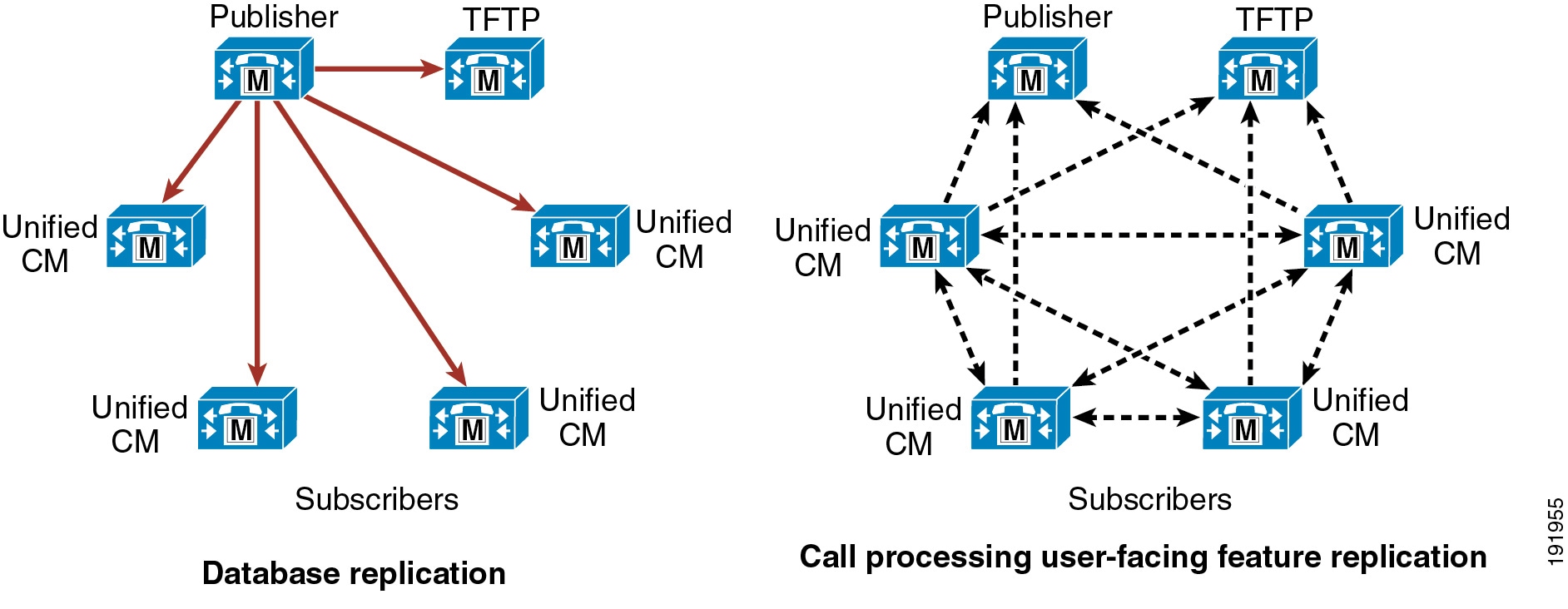
Intracluster Communications
There are two primary kinds of intracluster communications, or communications within a Unified CM cluster (see Figure 9-2 and Figure 9-3.) The first is a mechanism for distributing the database that contains all the device configuration information (see “Database replication” in Figure 9-2). The configuration database is stored on a publisher node, and a copy is replicated to the subscriber nodes of the cluster. Most of the database changes are made on the publisher and are then communicated to the subscriber databases, thus ensuring that the configuration is consistent across the members of the cluster and facilitating spatial redundancy of the database.
Database modifications for user-facing call processing features are made on the subscriber nodes to which an end-user device is registered. The subscriber nodes then replicate these database modifications to all the other nodes in the cluster, thus providing redundancy for the user-facing features. (See "Call processing user-facing feature replication" in Figure 9-2.) These features include:
- Call Forward All (CFA)
- Message waiting indicator (MWI)
- Privacy Enable/Disable
- Extension Mobility login/logout
- Hunt Group login/logout
- Device Mobility
- Certificate Authority Proxy Function (CAPF) status for end users and applications users
- Credential hacking and authentication
Figure 9-2 Replication of the Database and User-Facing Features
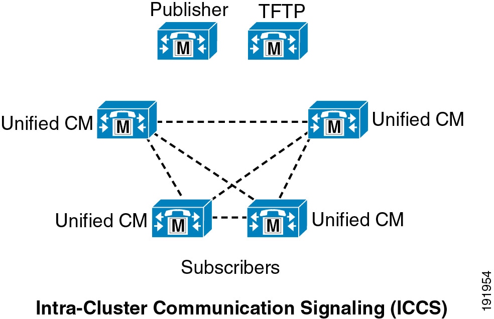
The second type of intracluster communication, called Intra-Cluster Communication Signaling (ICCS), involves the propagation and replication of run-time data such as registration of devices, locations bandwidth, and shared media resources (see Figure 9-3). This information is shared across all members of a cluster running the Cisco CallManager Service (call processing subscribers), and it ensures the optimum routing of calls between members of the cluster and associated gateways.
Figure 9-3 Intra-Cluster Communication Signaling (ICCS)
Intracluster Security
Each server node in a Unified CM cluster runs an internal dynamic firewall. The application ports on Unified CM are protected by source IP filtering. The dynamic firewall opens these application ports only to authenticated or trusted server nodes. (See Figure 9-4.)
Figure 9-4 Intracluster Security
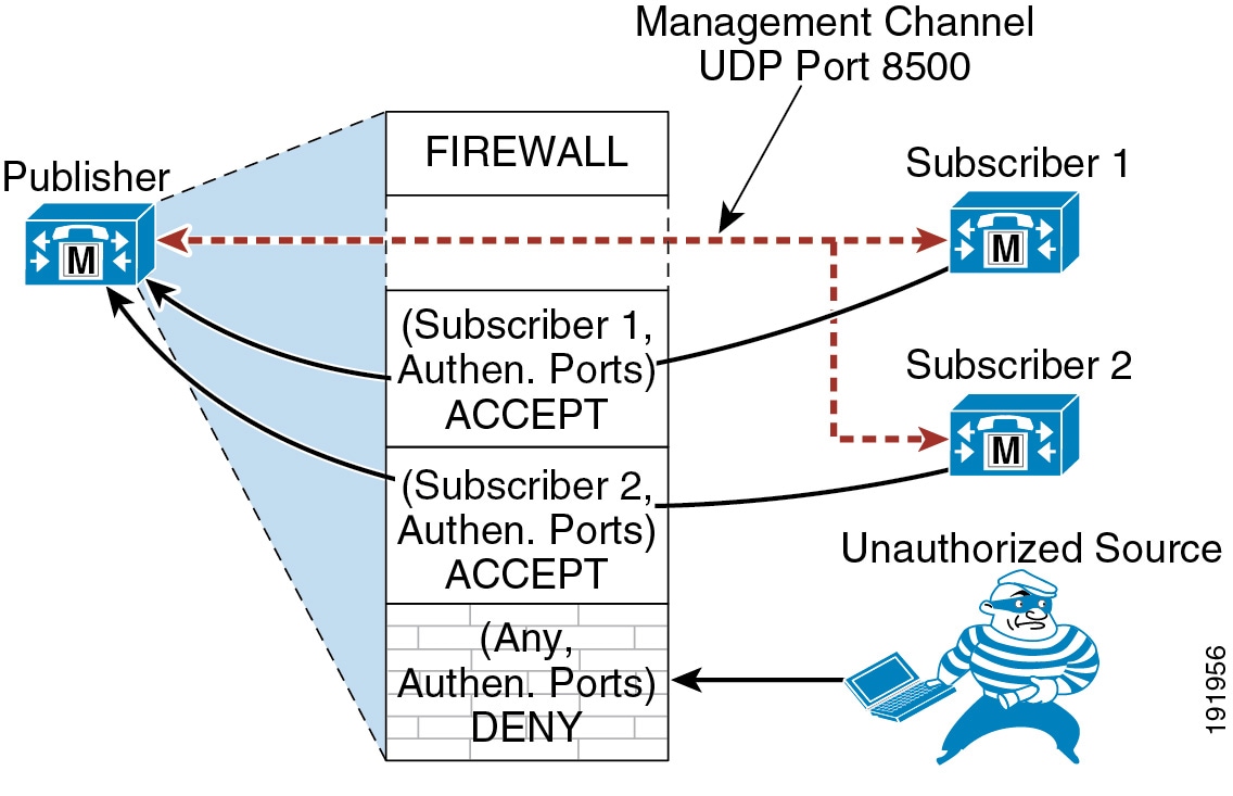
This security mechanism is applicable only between server nodes in a single Unified CM cluster. Unified CM subscribers are authenticated in a cluster before they can access the publisher's database. The intra-cluster communication and database replication take place only between authenticated server nodes. During the installation process, a subscriber node is authenticated to the publisher using a pre-shared key authentication mechanism. The authentication process involves the following steps:
1.![]() Install the publisher node using a security password.
Install the publisher node using a security password.
2.![]() Configure the subscriber node on the publisher by using Unified CM Administration.
Configure the subscriber node on the publisher by using Unified CM Administration.
3.![]() Install the subscriber node using the same security password used during publisher server installation.
Install the subscriber node using the same security password used during publisher server installation.
4.![]() After the subscriber is installed, the server node attempts to establish connection to the publisher on a management channel using UDP 8500. The subscriber sends all the credentials to the publisher, such as hostname, IP address, and so forth. The credentials are authenticated using the security password used during the installation process.
After the subscriber is installed, the server node attempts to establish connection to the publisher on a management channel using UDP 8500. The subscriber sends all the credentials to the publisher, such as hostname, IP address, and so forth. The credentials are authenticated using the security password used during the installation process.
5.![]() The publisher verifies the subscriber's credentials using its own security password.
The publisher verifies the subscriber's credentials using its own security password.
6.![]() The publisher adds the subscriber as a trusted source to its dynamic firewall table if the information is valid. The subscriber is allowed access to the database.
The publisher adds the subscriber as a trusted source to its dynamic firewall table if the information is valid. The subscriber is allowed access to the database.
7.![]() The subscriber gets a list of other subscriber nodes from the publisher. All the subscribers establish a management channel with each other, thus creating a mesh topology.
The subscriber gets a list of other subscriber nodes from the publisher. All the subscribers establish a management channel with each other, thus creating a mesh topology.
General Clustering Guidelines
The following guidelines apply to all Unified CM clusters:

Note![]() A cluster may contain a mix of virtual machines based on different OVA templates. For details, see the section on Mixing Unified CM OVA Templates.
A cluster may contain a mix of virtual machines based on different OVA templates. For details, see the section on Mixing Unified CM OVA Templates.
- Under normal circumstances, place all members of the cluster within the same LAN or MAN.
- If the cluster spans an IP WAN, follow the guidelines for clustering over an IP WAN as specified in the section on Clustering Over the IP WAN.
- A Unified CM cluster may contain as many as 20 server nodes, of which a maximum of eight call processing subscribers (nodes running the Cisco CallManager Service) are allowed. The other server nodes within the cluster may be configured as a dedicated database publisher, dedicated TFTP subscriber, or media resource subscriber.
- When deploying a two-node cluster, Cisco recommends that you do not exceed 1250 users in the cluster. Above 1250 users, a dedicated publisher and separate server nodes for primary and backup call processing subscribers is recommended.
- Business Edition 6000 runs on specific Test Reference Configuration servers and provides a single instance of Unified CM (a combined publisher and single subscriber instance). Additional Business Edition 6000 server(s) may be deployed to provide subscriber redundancy either in an active/standby or load balancing fashion for Unified CM as well as some other co-resident applications. However, the total number of users across this Unified CM cluster may not exceed 1,000, and the total number of configured devices across this Unified CM cluster may not exceed 1,200 with the medium-density server or 2,500 with the high-density server. Cisco recommends deploying redundant servers with load balancing so that the load is distributed among the Unified CM instances.
- Each Unified CM node instance can be a publisher node, call processing subscriber node, TFTP subscriber node, or media resource subscriber node. Only a single publisher node per cluster is supported.
- While the Cisco UCS B-Series Blade Servers and C-Series Rack-Mount Servers do support a local keyboard, video, and mouse (KVM) cable connection that provides a serial port, a Video Graphics Array (VGA) monitor port, and two Universal Serial Bus (USB) ports, the Unified CM VMware virtual application has no access to these USB and serial ports. Therefore, Unified CM no longer supports the Cisco Messaging Interface (CMI) service for Simplified Message Desk Interface (SMDI) integrations, fixed MoH audio source integration for live MoH audio feeds using the audio cards (MOH-USB-AUDIO=), or flash drives to these servers. The following alternate options are available:
–![]() For MoH live audio source feed, consider using Cisco IOS-based gateway multicast MoH for live audio source connectivity.
For MoH live audio source feed, consider using Cisco IOS-based gateway multicast MoH for live audio source connectivity.
–![]() For saving system install logs, use virtual floppy softmedia.
For saving system install logs, use virtual floppy softmedia.
–![]() There is no alternate option for the Cisco Messaging Interface (CMI) service for Simplified Message Desk Interface (SMDI) integrations.
There is no alternate option for the Cisco Messaging Interface (CMI) service for Simplified Message Desk Interface (SMDI) integrations.
Cisco TelePresence VCS Clustering
Cisco VCS can be deployed either as a standalone instance or as a cluster of up to six VCS nodes (VCS peers). Each VCS node in a cluster must have the same capacity. For example, if deployed as a virtual application, each VCS node must use the same OVA template. These rules apply to VCS Control and VCS Expressway (and also to Expressway C and Expressway E). Furthermore, all VCS peers in a VCS cluster must be of the same type. For example, a VCS Expressway node and a VCS Control node cannot be deployed as part of the same VCS cluster.
VCS clusters are designed to extend the resilience and capacity of a Cisco VCS installation. VCS peers in a cluster share bandwidth usage as well as routing, zone, FindMe and other configuration. Endpoints can register to any of the peers in the cluster; if they lose connection to their initial peer, they can re-register to another peer in the cluster.
Call licensing is carried out on a per-cluster basis. Any traversal or non-traversal call licenses that have been installed on a cluster peer are available for use by any peer within the cluster. If a cluster peer becomes unavailable, the call licenses installed on that peer will remain available to the rest of the cluster peers for a grace period of two weeks from the time the cluster lost contact with the peer. This maintains the overall license capacity of the cluster.
Every VCS peer in the cluster must have the same routing capabilities. If any VCS can route a call to a destination, it is assumed that all VCS peers in that cluster can route a call to that destination. If the routing is different on different VCS peers, then separate VCSs or VCS clusters must be used.
One VCS needs to be nominated as the VCS Configuration Master peer in the cluster. This VCS Configuration Master peer holds the cluster configuration and manages the cluster database. Cluster-wide configuration can be performed only on the Configuration Master, and all other VCS peers in the cluster then periodically replicate the configuration from the master. The VCS Configuration Master is configured as Peer 1, and the VCS cluster configuration page lists the VCS call agents in the cluster.
The procedure for forming a VCS cluster is the same for Cisco VCS Control, VCS Expressway, Expressway C and E, and VCS Directory.
The VCS node that is running the Configuration Master also performs call processing, whereas a Unified CM publisher would not typically perform call processing except for Cisco Business Edition or for small deployments.
Observe the following guidelines when deploying Cisco VCS:
- A VCS cluster can consist of up to six VCS peers.
- Each VCS in the cluster is a peer of every other VCS in the cluster.
- The round trip time between any two VCS peers in the cluster must be less than 30 ms.
- Every VCS must use a static IP address.
- Each VCS peer must have a unique system name.
- Each VCS peer can have a different DNS server.
- All VCS peers in the cluster must have the same software version.
- All VCS peers in the cluster must have the identical option keys installed, with the exception of call processing license numbers which may be different on each peer
- H.323 must be enabled on all VCS peers, even if all endpoints in the cluster are SIP only. H.323 is used for internal clustering between VCS peers.
- A VCS cluster can be formed by a combination of VCS nodes running on an appliance or running as a virtualized application.
For more information on Cisco VCS clusters, refer to the latest version of the Cisco TelePresence Video Communication Server Cluster Creation and Maintenance Deployment Guide, available at
http://www.cisco.com/en/US/products/ps11337/products_installation_and_configuration_guides_list.html
High Availability for Call Processing
You should deploy the call processing services within a Unified Communications System in a highly available manner so that a failure of a single call processing component will not render all call processing services unavailable.
Hardware Platform High Availability
You should select the call processing platform based not only on the size and scalability of a particular deployment, but also on the redundant nature of the platform hardware.
When possible, choose platforms with dual power supplies to ensure that a single power supply failure will not result in the loss of a platform. Plug platforms with dual power supplies into two different power sources to avoid the failure of one power circuit causing the entire platform to fail. The use of dual power supplies combined with the use of uninterruptible power supply (UPS) sources will ensure maximum power availability. In deployments where dual power supply platforms are not feasible, Cisco still recommends the use of a UPS in situations where building power does not have the required level of power availability.
Providing hardware platform high availability is even more critical when deploying virtualization because a platform failure could result in the failure of all the virtual machines running on that hardware platform. When possible, avoid running multiple instances of the same application that have similar functions on the same physical server; instead, distribute those virtual machines across multiple servers and even across multiple chassis if possible when using Cisco UCS B-Series Blade Servers.
Network Connectivity High Availability
Connectivity to the IP network is also a critical consideration for maximum performance and high availability. With Cisco Unified CME, use a minimum of two ports to connect to the network. With Unified CM, high availability for the network connectivity is attained at the host level by configuring the hypervisor virtual switch with multiple uplinks and thus by using multiple physical ports on the hardware platform. Therefore, a single virtual NIC defined in the OVA setting is sufficient. If you are using the VMware vSphere virtual switch, for example, configure NIC teaming for the switch uplinks. Also connect those multiple ports to a minimum of two upstream switches to provide resiliency if an upstream switch fails. Cisco VCS Control uses only one network interface, whether it is virtualized or not. A second network interface can be used with Cisco VCS Expressway for high-security deployments, for example, where the VCS Expressway is located in a DMZ between two separate firewalls on separate network segments. When VCS Control and Expressway are virtualized, provide network connectivity redundancy at the host level through multiple physical ports on the hardware platform, similarly to the configuration with Unified CM.
Connect platforms to the network at the highest possible speed to ensure maximum throughput, typically 1 Gbps or even 10 Gbps when using the large VCS configuration or using the UCS B-Series platform. Ensure that platforms are connected to the network using full-duplex.
In addition to speed and duplex of IP network connectivity, equally important is the resilience of this network connectivity. Unified communications deployments are highly dependent on the underlying network connectivity for true redundancy. For this reason it is critical to deploy and configure the underlying network infrastructure in a highly resilient manner. For details on designing highly available network infrastructures, see the chapter on Network Infrastructure. In all cases, the network should be designed so that, given a switch or router failure within the infrastructure, a majority of users will have access to a majority of the services provided within the deployment.
To maximize call processing availability, locate and connect call processing platforms in separate buildings and/or separate network switches when possible to ensure that the impact to call processing will be minimized if there is a failure of the building or network infrastructure switch. With Unified CM call processing, this means distributing cluster server nodes among multiple buildings or locations within the LAN or MAN deployment whenever possible. And at the very least, it means physically distributing network connections between different physical network switches in the same location.
Furthermore, even though Cisco Unified CME is a standalone call processing entity, providing physical distribution and therefore redundancy for this call processing entity still makes sense when deploying multiple call processing entities. Whenever possible in those scenarios, install each instance of Unified CME in a different physical location within the network, or at the very least physically attach them to different network switches.
Unified CM High Availability
Because of the underlying Unified CM clustering mechanism, a Unified Communications System has additional high availability considerations above and beyond hardware platform disk and power component redundancy, physical network location, and connectivity redundancy. This section examines call processing subscriber redundancy considerations, call processing load balancing, and redundancy of additional cluster services.
Call Processing Redundancy
Unified CM provides the following call processing redundancy configuration options or schemes:
- Two to one (2:1) — For every two primary call processing subscribers, there is one shared secondary or backup call processing subscriber.
- One to one (1:1) — For every primary call processing subscriber, there is a secondary or backup call processing subscriber.
These redundancy schemes are facilitated by the built-in registration failover mechanism within the Unified CM cluster architecture, which enables endpoints to re-register to a backup call processing subscriber node when the endpoint's primary call processing subscriber node fails. The registration failover mechanism can achieve failover rates for Skinny Client Control Protocol (SCCP) IP phones of approximately 125 registrations per second. The registration failover rate for Session Initiation Protocol (SIP) phones is approximately 40 registrations per second.
The call processing redundancy scheme you select determines not only the fault tolerance of the deployment, but also the fault tolerance of any upgrade.
With 1:1 redundancy, multiple primary call processing subscriber failures can occur without impacting call processing capabilities. With 2:1 redundancy, on the other hand, only one of the primary call processing subscribers out of the two primary call processing subscribers that share a backup call processing subscriber can fail without impacting call processing. However, if the total number of endpoints registered across both primary subscribers and the traffic to those two primary subscribers are within the capacity limits of the backup subscriber, then the backup subscriber is able to handle the failure of both primary subscribers.
Note![]() Do not deploy 2:1 redundancy if the total capacity utilization across the two primary subscribers would exceed the capacity of the backup subscriber. For example, if the call processing capacity or endpoints capacity utilization exceeds 50% on both primary subscribers, the backup subscriber would not be able to handle call processing services properly if both primary subscribers fail. In these scenarios, for example, some endpoints might not be able to register, some new calls might not be established, and some services and features might not operate properly because the backup subscriber system capacity has been exceeded.
Do not deploy 2:1 redundancy if the total capacity utilization across the two primary subscribers would exceed the capacity of the backup subscriber. For example, if the call processing capacity or endpoints capacity utilization exceeds 50% on both primary subscribers, the backup subscriber would not be able to handle call processing services properly if both primary subscribers fail. In these scenarios, for example, some endpoints might not be able to register, some new calls might not be established, and some services and features might not operate properly because the backup subscriber system capacity has been exceeded.
Likewise, with the 1:1 redundancy scheme, upgrades to the cluster can be performed with only a single set of endpoint registration failover periods impacting the call processing services. Whereas with the 2:1 redundancy scheme, upgrades to the cluster can require multiple registration failover periods.
A Unified CM cluster can be upgraded with minimal impact to the services. Two different versions (releases) of Unified CM may be on the same server node, one in the active partition and the other in the inactive partition. All services and devices use the Unified CM version in the active partition for all Unified CM functionality. During the upgrade process, the cluster operations continue using its current release of Unified CM in the active partition, while the upgrade version gets installed in the inactive partition. Once the upgrade process is complete, the server nodes can be rebooted to switch the inactive partition to the active partition, thus running the new version of Unified CM.
With the 1:1 redundancy scheme, the following steps enable you to upgrade the cluster while minimizing downtime:
Step 1![]() Install the new version of Unified CM in the inactive partition, first on the publisher and then on all subscribers (call processing, TFTP, and media resource subscribers). Do not reboot.
Install the new version of Unified CM in the inactive partition, first on the publisher and then on all subscribers (call processing, TFTP, and media resource subscribers). Do not reboot.
Step 2![]() Reboot the publisher and switch to the new version.
Reboot the publisher and switch to the new version.
Step 3![]() Reboot the TFTP subscriber node(s) one at a time and switch to the new version.
Reboot the TFTP subscriber node(s) one at a time and switch to the new version.
Step 4![]() Reboot any dedicated media resource subscriber nodes one at a time and switch to the new version.
Reboot any dedicated media resource subscriber nodes one at a time and switch to the new version.
Step 5![]() Reboot the backup call processing subscribers one at a time and switch to the new version.
Reboot the backup call processing subscribers one at a time and switch to the new version.
Step 6![]() Reboot the primary call processing subscribers one at a time and switch to the new version. Device registrations will fail-over to the previously upgraded and rebooted backup call processing subscribers. After each primary call processing subscriber is rebooted, devices will begin to re-register to the primary call processing subscriber.
Reboot the primary call processing subscribers one at a time and switch to the new version. Device registrations will fail-over to the previously upgraded and rebooted backup call processing subscribers. After each primary call processing subscriber is rebooted, devices will begin to re-register to the primary call processing subscriber.
With this upgrade method, there is no period (except for the registration failover period) when devices are registered to subscriber nodes that are running different versions of the Unified CM software. All these steps can be automated using Cisco Prime Collaboration.
While the 2:1 redundancy scheme allows for fewer server nodes in a cluster, registration failover occurs more frequently during upgrades, increasing the overall duration of the upgrade as well as the amount of time call processing services for a particular endpoint will be unavailable. Because there is only a single backup call processing subscriber per pair of primary call processing subscribers, it might be possible to reboot to the new version on only one of the primary call processing subscribers in a pair at a time in order to prevent oversubscribing the single backup call processing subscriber. As a result, there may be a period of time after the first primary call processing subscriber in each pair is switched to the new version, in which endpoint registrations will have to be moved from the backup subscriber to the newly upgraded primary subscriber before the endpoint registrations on the second primary subscriber can be moved to the backup subscriber to allow a reboot to the new version. During this time, not only will endpoints on the second primary call processing subscriber be unavailable while they re-register to the backup subscriber, but until they re-register to a node running the new version, they will also be unable to reach endpoints on other subscriber nodes that have already been upgraded.
Note![]() Before you do an upgrade, Cisco recommends that you back up the Unified CM and Call Detail Record (CDR) database to an external network directory using the Disaster Recovery Framework. This practice will prevent any loss of data if the upgrade fails.
Before you do an upgrade, Cisco recommends that you back up the Unified CM and Call Detail Record (CDR) database to an external network directory using the Disaster Recovery Framework. This practice will prevent any loss of data if the upgrade fails.
Note![]() Because an upgrade of a Unified CM cluster results in a period of time in which some or most devices lose registration and call processing services temporarily, you should plan upgrades in advance and implement them during a scheduled maintenance window. While downtime and loss of services to devices can be minimized by selecting the 1:1 redundancy scheme, there will still be some period of time in which call processing services are not available to some or all users.
Because an upgrade of a Unified CM cluster results in a period of time in which some or most devices lose registration and call processing services temporarily, you should plan upgrades in advance and implement them during a scheduled maintenance window. While downtime and loss of services to devices can be minimized by selecting the 1:1 redundancy scheme, there will still be some period of time in which call processing services are not available to some or all users.
For more information on upgrading Unified CM, refer to the install and upgrade guides available at
http://www.cisco.com/en/US/products/sw/voicesw/ps556/prod_installation_guides_list.html
Unified CM Redundancy with Survivable Remote Site Telephony (SRST)
Cisco IOS SRST provides highly available call processing services for endpoints in locations remote from the Unified CM cluster. Unified CM clustering redundancy schemes certainly provide a high level of redundancy for call processing and other application services within a LAN or MAN environment. However, for remote locations separated from the central Unified CM cluster by a WAN or other low-speed links, SRST can be used as a redundancy method to provide basic call processing services to these remote locations in the event of loss of network connectivity between the remote and central sites. Cisco recommends deploying SRST-capable Cisco IOS routers at each remote site where call processing services are considered critical and need to be maintained in the event that connectivity to the Unified CM cluster is lost. Endpoints at these remote locations must be configured with an appropriate SRST reference within Unified CM so that the endpoint knows what address to use to connect to the SRST router for call processing services when connectivity to Unified CM subscribers is unavailable.
Cisco Unified Enhanced SRST (E-SRST) on a Cisco IOS router can also be used at a remote site to provide backup call processing functionality in the event that connectivity to the central Unified CM cluster is lost. E-SRST provides more telephony features for the IP phones than are available with the regular SRST feature on a router. However, the endpoint capacities for Unified E-SRST are typically less than for basic SRST. Both SRST and E-SRST are supported with Cisco Unified SRST Manager, which synchronizes configurations from Unified CM with SRST and E-SRST, thus reducing manual configuration required in the branch SRST or E-SRST router and enabling users to have a similar calling experience in both SRST and normal modes.
Call Processing Subscriber Redundancy
Depending on the redundancy scheme chosen (see Call Processing Redundancy), the call processing subscriber will be either a primary (active) subscriber or a backup (standby) subscriber. In the load-balancing option, the subscriber can be both a primary and backup subscriber. When planning the design of a cluster, you should generally dedicate the call processing subscribers to this function. In larger-scale or higher-performance clusters, the call processing service should not be enabled on the publisher and TFTP subscriber nodes. 1:1 redundancy uses dedicated pairs of primary and backup subscribers, while 2:1 redundancy uses a pair of primary subscribers that share one backup subscriber.
The following figures illustrate typical cluster configurations to provide call processing redundancy with Unified CM.
Figure 9-5 Basic Redundancy Schemes
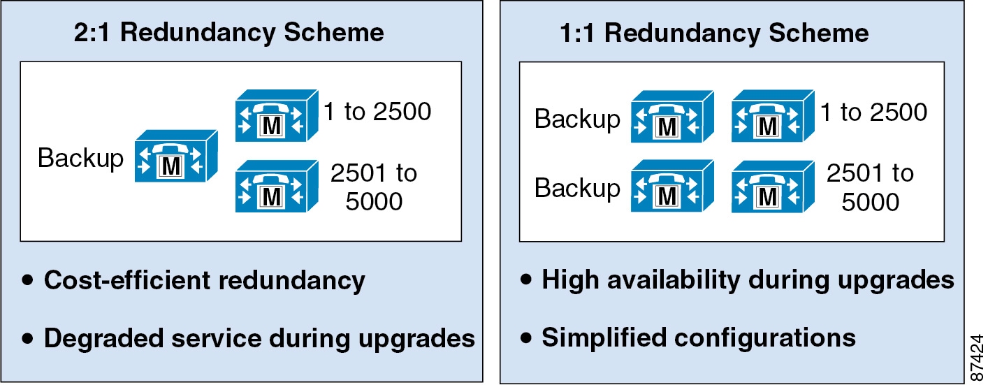
Figure 9-5 illustrates the two basic redundancy schemes available. In each case the backup server node must be capable of handling the capacity of at least a single primary call processing server node failure. In the 2:1 redundancy scheme, the backup might have to be capable of handling the failure of a single call processing server node or potentially both primary call processing server nodes, depending on the requirements of a particular deployment. For information on capacity sizing and choosing the OVA templates, see the section on Capacity Planning for Call Processing.
Note![]() 2:1 redundancy is not supported with the 10,000-User OVA template due to potential overload on the backup subscriber.
2:1 redundancy is not supported with the 10,000-User OVA template due to potential overload on the backup subscriber.
Figure 9-6 1:1 Redundancy Configuration Options
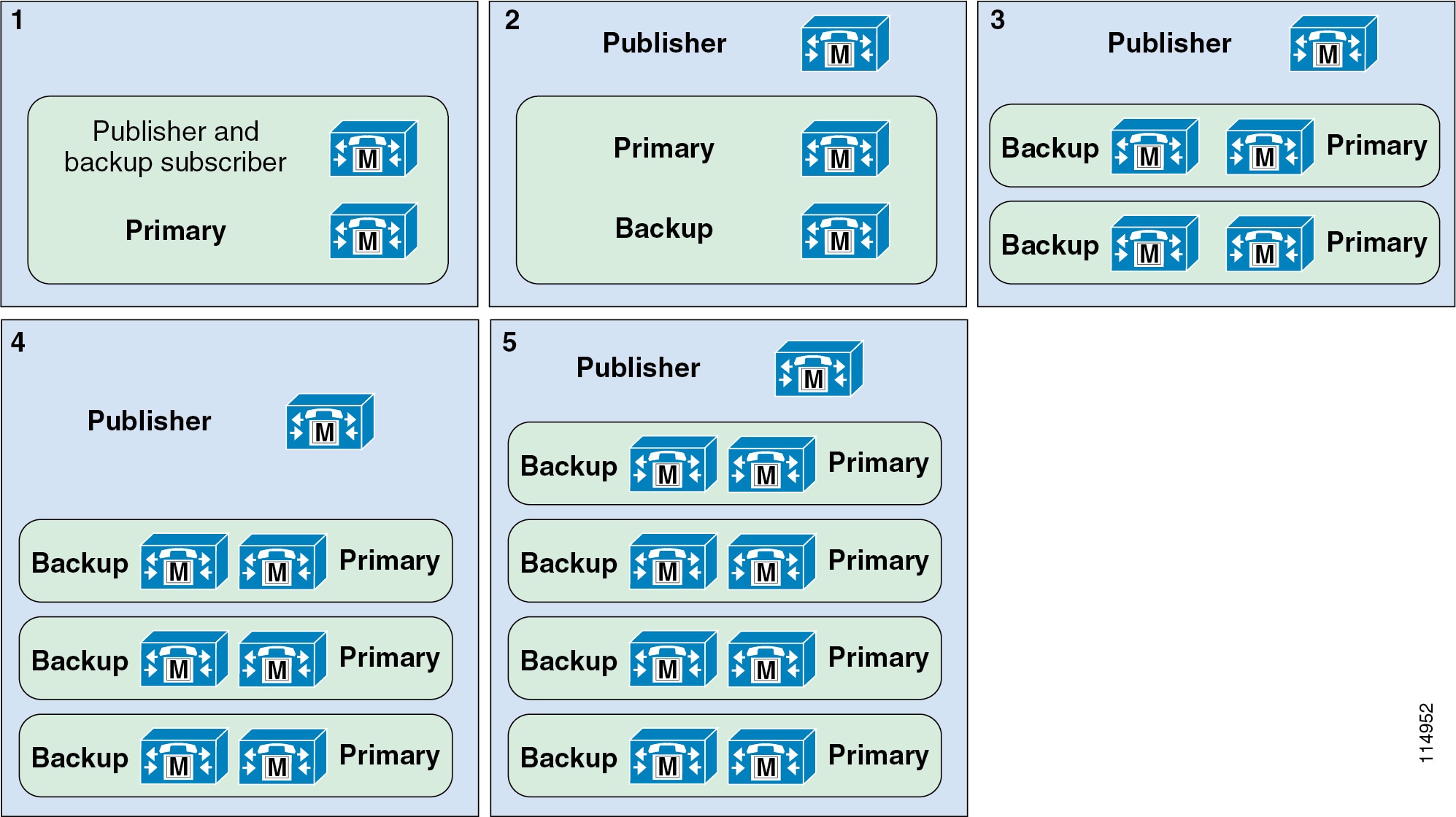
Figure 9-7 2:1 Redundancy Configuration Options
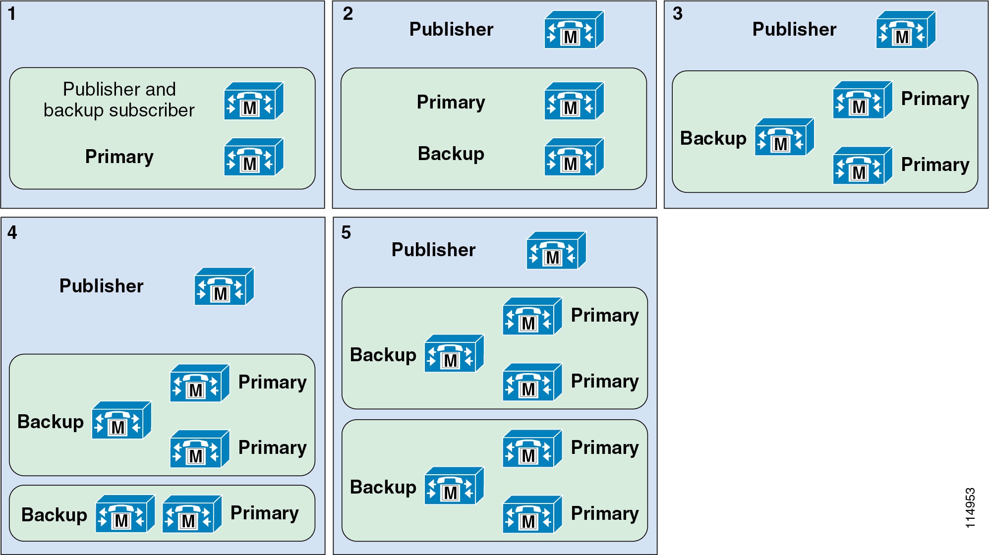
In Figure 9-6, the five options shown all indicate 1:1 redundancy. In Figure 9-7, the five options shown all indicate 2:1 redundancy. In both cases, Option 1 is used for clusters supporting less than 1250 users. Options 2 through 5 illustrate increasingly scalable clusters for each redundancy scheme. The exact scale depends on the hardware platforms chosen or required.
These illustrations show only publisher and call processing subscribers. They do not account for other subscriber nodes such as TFTP and media resources.
Note![]() It is possible to define up to three call processing subscribers per Unified CM group. Adding a tertiary subscriber for additional backup extends the above redundancy schemes to 2:1:1 or 1:1:1 redundancy. However, with the exception of using tertiary subscriber nodes in deployments with clustering over the WAN (see Remote Failover Deployment Model), tertiary subscriber redundancy is not recommended for endpoint devices located in remote sites because failover to SRST will be further delayed if the endpoint must check for connectivity to a tertiary subscriber. The tertiary subscribers also count against the maximum number of call processing subscribers in a cluster (8 call processing subscriber nodes).
It is possible to define up to three call processing subscribers per Unified CM group. Adding a tertiary subscriber for additional backup extends the above redundancy schemes to 2:1:1 or 1:1:1 redundancy. However, with the exception of using tertiary subscriber nodes in deployments with clustering over the WAN (see Remote Failover Deployment Model), tertiary subscriber redundancy is not recommended for endpoint devices located in remote sites because failover to SRST will be further delayed if the endpoint must check for connectivity to a tertiary subscriber. The tertiary subscribers also count against the maximum number of call processing subscribers in a cluster (8 call processing subscriber nodes).
Although not shown in the Figure 9-6 or Figure 9-7, it is also possible to deploy a single-node cluster. The single-node cluster should not exceed 1000 endpoint configuration and registrations. Note that in a single-node configuration, there is no backup call processing subscriber and therefore no cluster redundancy mechanism. Survivable Remote Site Telephony (SRST) can be used as a redundancy mechanism in these types of deployments to provide minimal call processing services during periods when Unified CM is not available. However, Cisco does not recommend a single-node deployment for production environments.
In Unified CM clusters with the 1:1 redundancy scheme, device registration and call processing services can be load-balanced across the primary and backup call processing subscriber.
Normally a backup server node has no devices registered to it unless its primary is unavailable. This makes it easier to troubleshoot a deployment because there is a maximum of four primary call processing subscriber nodes that will be handling the call processing load at a given time. Further, this potentially simplifies configuration by reducing the number of Unified CM redundancy groups and device pools.
In a load-balanced deployment, up to half of the device registration and call processing load can be moved from the primary to the secondary subscriber by using the Unified CM redundancy groups and device pool settings. In this way each primary and backup call processing subscriber pair provides device registration and call processing services to as many as half of the total devices serviced by this pair of call processing subscribers. This is referred to as 50/50 load balancing. The 50/50 load balancing model provides the following benefits:
- Load sharing — The registration and call processing load is distributed on multiple server nodes, which can provide faster response time.
- Faster failover and failback — Because all devices (such as IP phones, CTI ports, gateways, trunks, voicemail ports, and so forth) are distributed across all active subscribers, only some of the devices fail-over to the secondary subscriber if the primary subscriber fails. In this way, you can reduce by 50% the impact of any server node becoming unavailable.
To plan for 50/50 load balancing, calculate the capacity of a cluster without load balancing, and then distribute the load across the primary and backup subscribers based on devices and call volume. To allow for failure of the primary or the backup server node, do not let the total load on the primary and secondary subscribers exceed that of a single subscriber node.
Note![]() During upgrades of a Unified CM cluster with 50/50 load balancing, upgrades to the backup call processing subscriber will result in devices registered to that subscriber (half of the total devices serviced by the primary and backup subscriber pair) failing over to the primary call processing subscriber.
During upgrades of a Unified CM cluster with 50/50 load balancing, upgrades to the backup call processing subscriber will result in devices registered to that subscriber (half of the total devices serviced by the primary and backup subscriber pair) failing over to the primary call processing subscriber.
TFTP Redundancy
Cisco recommends deploying more than one dedicated TFTP subscriber node for a large Unified CM cluster, thus providing redundancy for TFTP services. While two TFTP subscribers are typically sufficient, more than two TFTP server nodes can be deployed in a cluster.
In addition to providing one or more redundant TFTP subscribers, you must configure endpoints to take advantage of these redundant TFTP nodes. When configuring the TFTP options using DHCP or statically, define a TFTP subscriber node IP address array containing the IP addresses of both TFTP subscriber nodes within the cluster. In this way, by creating two DHCP scopes with two different IP address arrays (or by manually configuring endpoints with two different TFTP subscriber node IP addresses), you can assign half of the endpoint devices to use TFTP subscriber A as the primary and TFTP subscriber B as the backup, and the other half to use TFTP subscriber B as the primary and TFTP subscriber A as the backup. In addition to providing redundancy during a failure of one TFTP subscriber, this method of distributing endpoints across multiple TFTP subscribers provides load balancing so that one TFTP subscriber is not handling all the TFTP service load.
Note![]() When adding a specific binary or firmware load for a phone or gateway, you must add the file(s) to each TFTP subscriber node in the cluster.
When adding a specific binary or firmware load for a phone or gateway, you must add the file(s) to each TFTP subscriber node in the cluster.
CTI Manager Redundancy
All CTI integrated applications communicate with a call processing subscriber node running the CTI Manager service. Further, most CTI applications have the ability to specify redundant CTI Manager service nodes. For this reason, Cisco recommends activating the CTI Manager service on at least two call processing subscribers within the cluster. With both a primary and backup CTI Manager configured, in the event of a failure the application will switch to a backup CTI Manager to receive CTI services.
As stated previously, the CTI Manager service can be enabled only on call processing subscribers, therefore there is a maximum of eight CTI Managers per cluster. Cisco recommends that you load-balance CTI applications across the enabled CTI Managers in the cluster to provide maximum resilience, performance, and redundancy.
Generally, it is good practice to associate devices that will be controlled or monitored by a CTI application with the same server node pair used for the CTI Manager service. For example, an interactive voice response (IVR) application requires four CTI ports. They would be provisioned as follows, assuming the use of 1:1 redundancy and 50/50 load balancing:
- Two CTI ports would have a Unified CM redundancy group of server node A as the primary call processing subscriber and server node B as the backup subscriber. The other two ports would have a Unified CM redundancy group of server node B as the primary subscriber and server node A as the backup subscriber.
- The IVR application would be configured to use the CTI Manager on subscriber A as the primary and subscriber B as the backup.
The above example allows for redundancy in case of failure of the CTI Manager on subscriber A and also allows for the IVR call load to be spread across two server nodes. This approach also minimizes the impact of a Unified CM subscriber node failure.
For more details on CTI and CTI Manager, see Computer Telephony Integration (CTI).
Virtual Machine Placement and Hardware Platform Redundancy
With virtualization there are redundancy considerations because of the virtual nature of server nodes: namely, the installation and residency of Unified CM server node instances across physical servers.
As illustrated by the example in Figure 9-8, observe the following guidelines when deploying Unified CM to ensure the highest level of call processing redundancy:
- Each primary call processing subscriber node instance should reside on a different physical server than its backup call processing subscriber node instance. This ensures that the failure of a server containing the primary call processing node instance does not impact the system's ability to provide endpoints with access to their backup call processing subscriber node.
- When deploying multiple TFTP or media resource subscriber nodes instances for redundancy of those services, always distribute redundant subscriber nodes across more than one server to ensure that a failure of a single server does not eliminate those services. This ensures that, given the failure of a blade containing a TFTP or media resource subscriber, endpoints will still be able to access TFTP and media resource services on a subscriber node residing on another server. Endpoints can also be distributed among redundant TFTP and media resource subscriber node instances to balance system load in non-failure scenarios.
- When deploying CTI applications, always make sure that call processing subscriber node instances running the CTI Manager service are distributed across more than one server to ensure that a failure of a single server does not eliminate CTI services. Further, CTI applications should be configured to use the CTI Manager service running on the subscriber node instance on one server as the primary CTI Manager and the CTI Manager service running on the subscriber node on another server as the backup CTI Manager.
Figure 9-8 Unified CM Server Node Distribution on UCS

When using blade servers with a chassis (for example, B-Series blade servers with a Cisco UCS 5100 Blade chassis), in addition to distributing subscriber node instances across multiple blades, you may distribute subscriber node instances across multiple blade chassis for additional redundancy and scalability.
For more information about redundancy and provisioning of host resources for virtual machines, refer to the documentation at http://www.cisco.com/go/uc-virtualized.
Cisco Business Edition High Availability
To provide high availability for Unified CM with Cisco Business Edition 6000S, deploying SRST is recommended, even though clustering additional Unified CM node(s) and adding hardware servers are also supported.
With Cisco Business Edition 6000M, Cisco Business Edition 6000H, and Cisco Business Edition 7000, high availability is provided by clustering additional Cisco Unified CM node(s). Additional Business Edition server(s) can be deployed to provide high availability for call processing as well as other applications and services.
Note![]() More than two physical servers may be clustered to provide additional redundancy and/or geographic distribution as with a clustering over the WAN deployment. However, with Cisco Business Edition 6000, the additional server(s) only provides redundancy and not a capacity increase. For example, with BE6000S, the total number of users across the cluster may not exceed 150; with BE6000M and BE6000H, the total number of users across the cluster may not exceed 1,000. A deployment exceeding this limit is considered to be a standard Unified CM cluster, and as such the deployment must follow high availability design guidance for standard Unified CM. (See Unified CM High Availability.) With Cisco Business Edition 7000, the capacity is not limited to 1,000 users; rather, the standard application capacity planning and design rules apply.
More than two physical servers may be clustered to provide additional redundancy and/or geographic distribution as with a clustering over the WAN deployment. However, with Cisco Business Edition 6000, the additional server(s) only provides redundancy and not a capacity increase. For example, with BE6000S, the total number of users across the cluster may not exceed 150; with BE6000M and BE6000H, the total number of users across the cluster may not exceed 1,000. A deployment exceeding this limit is considered to be a standard Unified CM cluster, and as such the deployment must follow high availability design guidance for standard Unified CM. (See Unified CM High Availability.) With Cisco Business Edition 7000, the capacity is not limited to 1,000 users; rather, the standard application capacity planning and design rules apply.
Cisco TelePresence VCS High Availability
Cisco VCS offers high availability by allowing deployment of up to six VCS peers in a VCS cluster. This applies to Cisco VCS Control and Cisco VCS Expressway. If a VCS peer becomes unavailable, endpoints use another peer in the VCS cluster for registration and call processing.
High availability can be achieved through different methods depending on the endpoint capabilities.
SIP-capable endpoints that support SIP Outbound (RFC 5626) can be configured to register to multiple peers simultaneously. The benefit of maintaining simultaneous registrations is to avoid any downtime if a VCS server fails. If endpoints are SIP-based and RFC 5626 compliant, then this is the preferred method for providing VCS registration redundancy.
Note![]() In this configuration, because a SIP endpoint is actively registered to multiple VCS peers, that SIP endpoint has to be accounted for on each of those VCS peers with regard to capacity and registration license.
In this configuration, because a SIP endpoint is actively registered to multiple VCS peers, that SIP endpoint has to be accounted for on each of those VCS peers with regard to capacity and registration license.
If SIP endpoints do not support SIP Outbound, high availability can be achieved by using the Domain Name Server (DNS) record for the VCS cluster.
For H.323 endpoints, the high availability mechanism depends on whether the endpoint registers to VCS for the first time or whether it re-registers subsequently. Redundancy for the initial registration is provided by the use of DNS Record for the VCS cluster. Redundancy for subsequent registration is done through the H.323 Alternate Gatekeepers list that is returned by VCS to the H.323 endpoint through the initial registration. This list contains the addresses of VCS cluster peer members. If the endpoint loses connection with the first VCS peer it registered with, it will select another peer from the Alternate Gatekeepers list and try to re-register with that VCS.
For SIP and H.323 endpoints, it is also possible to configure the IP address of one of the VCS peers, but this method should be used only as a last resort because it does not provide registration redundancy.
As mentioned above, Domain Name Server (DNS) Records can be used to provide redundancy. SIP or H.323 endpoints may leverage a DNS server to find the IP address of another VCS node with which to attempt registration if initial registration failed with the previous node. Relying on DNS for registration redundancy does introduce some delay because endpoints must wait some period of time after sending an initial registration request before sending a new registration request to another VCS node. There are two methods for enabling DNS record types, depending on the endpoint:
- DNS SRV (Service Records) — For endpoints that support DNS SRV records, set up a DNS SRV record for the DNS name of the VCS cluster, giving each cluster peer an equal weighting and priority. The endpoint should then be configured with the DNS name of the cluster. On startup the endpoint issues a DNS SRV request and receives back the addresses of each VCS cluster peer. The endpoint will then try to register with each peer in turn. If you are using DNS to achieve registration redundancy, DNS SRV records are recommended if supported by the endpoint, because this method provides faster failover times than relying on round-robin between DNS A-records.
- DNS Round-Robin — For endpoints that do not support DNS SRV records, set up a DNS A-record for the DNS name of the VCS cluster, and configure it to supply a round-robin list of IP addresses for each VCS cluster peer. The endpoint should then be configured with the DNS name of the cluster. On startup the endpoint performs a DNS A-record lookup and receives back an address of a peer taken from the round-robin list. The endpoint will try to register with that peer. If that peer is not available, the endpoint performs another DNS lookup, and the server will respond with the next peer in the list. This process is repeated until the endpoint registers with a VCS.
For more information, refer to the latest version of the Cisco TelePresence Video Communication Server Cluster Creation and Maintenance Deployment Guide, available at
http://www.cisco.com/en/US/products/ps11337/products_installation_and_configuration_guides_list.html
When deploying Cisco VCS as a virtual application and clustering VCS nodes, Cisco strongly recommends using at least two physical hardware hosts and having VCS peers running on those separate hosts. The same guidelines as with Unified CM can be applied (see Virtual Machine Placement and Hardware Platform Redundancy).
When Cisco VCS Control is deployed as part of Cisco Business Edition 6000, high availability is also possible by adding other Cisco VCS Control peer(s) in the same VCS Control cluster. When Cisco VCS Expressway is added to a Cisco Business Edition 6000 system, high availability is also possible by adding other Cisco VCS Expressway peer(s) in the same VCS Expressway cluster. When you add Cisco VCS peer(s) for high availability, Cisco recommends deploying them on separate host(s). A two-node VCS Control cluster and a two-node VCS Expressway cluster can be deployed on two servers, for example, with each server hosting one VCS Control node and one VCS Expressway node. For more details on deploying a VCS Control node and a VCS Expressway node on the same ESXi host, refer to the document Installing Cisco Video Communications Server Expressway on a Business Edition 6000 Server, available at
http://www.cisco.com/en/US/products/ps11369/prod_technical_reference_list.html
Capacity Planning for Call Processing
Call processing capacity planning is critical for successful unified communications deployments. Given the many features and functions provided by call processing services as well as the many types of devices for which call processing entities can provide registration and transaction services, it important to size the call processing infrastructure and its individual components to ensure they meet the capacity needs of a particular deployment.
IP phones, software clients, voicemail ports, CTI (TAPI or JTAPI) devices, gateways, and DSP resources for media services such as transcoding and conferencing, all register to a call processing entity. Each of these devices requires resources from the call processing platform with which it is registered. The required resources can include memory, processor usage, and disk I/O.
Besides adding registration load to call processing platforms, after registration each device then consumes additional platform resources during transactions, which are normally in the form of calls. For example, a device that makes only 6 calls per hour consumes fewer resources than a device making 12 calls per hour.
For more information about call processing sizing and for a complete discussion of system sizing, capacity planning, and deployment considerations, see the chapter on Collaboration Solution Sizing Guidance.
Unified CME Capacity Planning
When deploying Unified CME, it is critical to select a Cisco IOS router platform that provides the desired capacity in terms of number of supported endpoints required. In addition, platform memory capacity should also be considered if the Unified CME router is providing additional services above and beyond call processing, such as IP routing, DNS lookup, dynamic host configuration protocol (DHCP) address services, or VXML scripting.
Unified CME can support a maximum of 450 endpoints on a single Cisco IOS platform; however, each router platform has a different endpoint capacity based on the size of the system. Because Unified CME is not supported within the Cisco Unified Communications Sizing Tool, it is imperative to follow capacity information provided in the product data sheets available at
http://www.cisco.com/en/US/products/sw/voicesw/ps4625/products_data_sheets_list.html
Unified CM Capacity Planning
This section examines capacity planning for Unified CM. The recommendations provided in this section are based on calculations made using the Unified Communications Sizing Tool, with default trace levels and call detail records (CDRs) enabled. In some cases higher levels of performance and capacity can be achieved by disabling, reducing, or reconfiguring other functions that are not directly related to processing calls. Enabling and increasing utilization of these functions can also have an impact on the call processing capabilities of the system and in some cases can reduce the overall capacity. These functions include tracing, call detail recording, highly complex dial plans, and other services that are co-resident on the Unified CM platform. Highly complex dial plans can include multiple line appearances as well as large numbers of partitions, calling search spaces, route patterns, translations, route groups, hunt groups, pickup groups, route lists, call forwarding, co-resident services, and other co-resident applications. All of these functions can consume additional resources within the Unified CM system.
You can use the following technique to improve system performance:
A Unified CM cluster with a very large dial plan containing many gateways, route patterns, translation patterns, and partitions, can take an extended amount of time to initialize when the Cisco CallManager Service is first started. If the system does not initialize within the default time, you can modify the system initialization timer (a Unified CM service parameter) to allow additional time for the configuration to initialize. For details on the system initialization time, refer to the online help for Service Parameters in Unified CM Administration.
Unified CM Capacity Planning Guidelines and Endpoint Limits
The following capacity guidelines apply to Cisco Unified CM:
- Within a cluster, a maximum of 8 call processing subscriber nodes can be enabled with the Cisco CallManager Service. Other server nodes may be used for more dedicated functions such as publisher, TFTP subscribers, and media resources subscribers.
- Each Unified CM node can support registration for a maximum of 10,000 secured or unsecured SCCP or SIP endpoints. Each cluster can support configuration and registration for a maximum of 40,000 secured or unsecured SCCP or SIP endpoints.
- There are different OVA template sizes for Cisco Unified CM, depending on the required capacity. The names of the Unified CM OVA templates correspond to the maximum number of users per node, assuming that each user has one phone. When the ratio of number phones per user is different than one, the OVA template names actually correspond to the maximum number of endpoints per node. Depending on different variables such as BHCA and feature set used, the actual number of users or endpoints could be lower. To validate the sizing of a deployment, use the Cisco Unified Communications Sizing Tool, available at
With Business Edition 6000, the Unified CM OVA template names usually refer to the maximum number of users per node. The number of phones could be higher. For more details, see the section on Cisco Business Edition Capacity Planning.
- Some OVA templates require more powerful hardware platforms. For instance, the Unified CM 2.5k, 7.5k, and 10k user OVA templates require more powerful servers than the 1k user OVA template. For more details, refer to www.cisco.com/go/uc-virtualized.
- The default trace setting for the CallManager service is 1,500 files of 10 MB for Signaling Distribution Layer (SDL) traces. Unless specific troubleshooting under high call rates requires increasing the maximum file setting, the default settings are sufficient for collecting sufficient traces in most circumstances.
For more information about Unified CM capacity planning considerations, including sizing limits as well as a complete discussion of system sizing, capacity planning, and deployment considerations, see the chapter on Collaboration Solution Sizing Guidance.
Megacluster
The term megacluster defines and identifies certain Unified CM deployments that allow for further increases in scalability. A megacluster provides more device capacity through the support of additional Unified CM subscriber nodes, with a maximum of eight Unified CM subscriber pairs (1:1 redundancy) per megacluster, thus allowing for a maximum of 80,000 devices.
A megacluster can also be deployed where customers simply require non-locally redundant call processing functionality, rather than using Survivable Remote Site Telephony (SRST), to scale beyond the maximum eight sites allowed in a standard cluster deployment and up to 16 Unified CM subscriber nodes per megacluster. For example, consider a large hospital that has twelve locations and each location has only 1,000 devices. This total of 12,000 devices could be accommodated within a standard cluster, which has a maximum device capacity of 40,000 devices. However, in this case it is the need for additional Unified CM subscribers, rather than additional device capacity, that requires a megacluster deployment. In this example, a Unified CM subscriber node could be deployed in each location, and each Unified CM subscriber could serve as the primary subscriber for the local endpoints and as a backup subscriber for endpoints from another location.
When considering a megacluster deployment, the primary areas impacting capacity are as follows:
- The megacluster may contain a total of 21 server nodes consisting of 16 subscriber nodes, 2 TFTP server nodes, 2 music on hold (MoH) server nodes, and 1 publisher node.
- Unified CM must be deployed with the OVA 7,500-User or 10,000-User OVA template.
- Redundancy model must be 1:1.
All other capacities relating to a standard cluster also apply to a megacluster. Note that support for a megacluster deployment is granted only following the successful review of a detailed design, including the submission of the results from the Cisco Unified Communications Sizing Tool. For more information about the Cisco Unified Communications Sizing Tool and the sizing of Unified CM standard clusters and megaclusters, see the chapter on Collaboration Solution Sizing Guidance.
Due to the many potential complexities surrounding megacluster deployments, customers who wish to pursue such a deployment must engage either their Cisco Account Team, Cisco Advanced Services, or their certified Cisco Unified Communications Partner.
Note![]() Unless otherwise specified, all information contained within this SRND that relates to call processing deployments (including capacity, high availability, and general design considerations) applies only to a standard cluster.
Unless otherwise specified, all information contained within this SRND that relates to call processing deployments (including capacity, high availability, and general design considerations) applies only to a standard cluster.
Cisco Business Edition Capacity Planning
Cisco Business Edition 6000S supports up to 150 users and 300 devices with Unified CM. Cisco Business Edition 6000M supports up to 1,000 users and 1,200 devices. Cisco Business Edition 6000H supports up to 1,000 users and 2,500 devices. BE6000M and BE600H support a maximum of 5,000 BHCA. With BE6000, adding nodes or hardware platforms is supported to provide high availability, but that does not increase capacity.
With Cisco Business Edition 7000, the normal capacity planning rules of Unified CM or virtualized VCS apply. For example, user and endpoint capacity increases when nodes are added.
For more information about Cisco Business Edition capacity planning considerations, including sizing examples and per-platform sizing limits as well as a complete discussion of system sizing, capacity planning, and deployment considerations, see the chapter on Collaboration Solution Sizing Guidance.
For additional details on Cisco Business Edition capacities as well as all other information, refer to the following product documentation:
http://www.cisco.com/c/en/us/products/unified-communications/business-edition-6000/index.html
http://www.cisco.com/c/en/us/products/unified-communications/business-edition-7000/index.html
http://www.cisco.com/c/en/us/support/unified-communications/business-edition-6000/products-device-support-tables-list.html
Cisco TelePresence VCS Capacity Planning
In terms of capacity, with the largest OVA template, one Cisco VCS Control node can support:
To increase the capacity, you can deploy a VCS cluster with up to six VCS peer members. A VCS cluster not only provides higher scalability but also provides redundancy in an N+2 configuration. A cluster has a total maximum capacity equal to four times that of a single VCS, and the cluster supports up to two VCS nodes failing without impacting the cluster capacity.
Therefore the capacity of a cluster with six VCSs can support:
Multiple separate VCS clusters can also be deployed. They could be interconnected through a directory VCS, for example.
For more information about Cisco TelePresence VCS capacity planning considerations, including sizing limits as well as a complete discussion of system sizing, capacity planning, and deployment considerations, refer to the Cisco VCS product documentation available at
http://www.cisco.com/c/en/us/support/unified-communications/telepresence-video-communication-server-vcs/tsd-products-support-series-home.html
Design Considerations for Call Processing
Observe the following design recommendations and guidelines when deploying Cisco call processing:
- Cisco Unified CM runs only as a virtualized application on the VMware Hypervisor. It does not run directly on a hardware platform without the VMware Hypervisor.
- You can enable a maximum of 8 call processing subscriber nodes (nodes running the Cisco CallManager Service) within a Cisco Unified CM cluster. Additional server nodes may be dedicated and used for publisher, TFTP, and media resources services. An approved megacluster deployment supports a maximum of 16 call processing subscriber nodes.
- Each Unified CM cluster can support configuration and registration for a maximum of 40,000 secured or unsecured endpoints. For additional information about Unified CM capacity planning, including per-platform sizing limits, see the chapter on Collaboration Solution Sizing Guidance.
- When deploying a two-node cluster, Cisco recommends that you do not exceed 1250 users in the cluster. Above 1250 users, Cisco recommends a dedicated publisher and separate nodes for primary and backup call processing subscribers.
- Cisco recommends using the same OVA template for all nodes in a cluster.
- 2:1 redundancy is not supported when using the 10,000-User OVA template due to potential overload on the backup subscriber
- Use multiple physical ports in the hardware platform for the virtual machine network traffic, and use a minimum of two upstream switches to provide network connectivity redundancy. If using the VMware vSphere virtual switch, use VMware NIC teaming.
- Whenever possible, distribute the hardware platforms across multiple physical switches within the network and across multiple physical locations within the same network to minimize the impact of a switch failure or the loss of a particular network location.
- Deploy SRST or E-SRST on Cisco IOS routers at remote locations to provide fallback call processing services in the event that these locations lose connectivity to the Unified CM cluster.
- Cisco recommends that you leave voice activity detection (VAD) disabled within the Unified CM cluster. VAD is disabled by default in the Unified CM service parameters, and you should disable it on H.323 and SIP dial peers configured on Cisco IOS gateways by using the no vad command.
- Ensure that the Unified CM nodes are distributed across different servers so that backup or redundant subscriber nodes are on different servers than the primary subscriber nodes.
- Both UCS B-Series Blade Servers and mid-end or high-end C-Series Rack-Mount Servers support all Unified CM Open Virtualization Archive (OVA) template sizes (including, for example, the OVA templates that support 10,000 devices). However, some smaller servers support only the small OVA template size. For information on proper OVA template sizing as well as the use of the Cisco Unified Communications Sizing Tool, see the chapter on Collaboration Solution Sizing Guidance.
- Access to the USB and serial ports on the hardware platform is not supported with Unified CM virtual machines. Therefore, attaching fixed live audio sources for MoH, making a serial SMDI connection to a legacy voicemail system, or attaching a USB flash drive for writing log files are also not supported. The following alternative options are available:
–![]() For MoH live audio source feed, consider using Cisco IOS-based gateway multicast MoH for live audio source connectivity.
For MoH live audio source feed, consider using Cisco IOS-based gateway multicast MoH for live audio source connectivity.
–![]() For saving system installation logs, use virtual floppy softmedia.
For saving system installation logs, use virtual floppy softmedia.
–![]() There is no support for SMDI serial connection.
There is no support for SMDI serial connection.
- Cisco Business Edition 6000S supports a maximum of 150 users and 300 endpoints with Unified CM. Unified CM is typically deployed as a combined publisher and single subscriber instance. Deploying SRST is recommended for redundancy, even though another Unified CM node running on a separate Cisco Business Edition 6000S platform, for example, could also be deployed for redundancy.
- Cisco Business Edition 6000M and Cisco Business Edition 6000H support a maximum of 1,000 users. Unified CM is deployed as a combined publisher and single subscriber instance. To provide Unified CM redundancy, additional hardware server(s) hosting Unified CM subscriber node(s) can be deployed.
Note![]() More than two servers may be clustered for a BE6000 deployment to provide additional redundancy and/or geographic distribution; however, the capacity limits are not increased. For example, the total number of users across the cluster may not exceed 150 with BE6000S, or 1,000 with BE6000M or BE6000H.
More than two servers may be clustered for a BE6000 deployment to provide additional redundancy and/or geographic distribution; however, the capacity limits are not increased. For example, the total number of users across the cluster may not exceed 150 with BE6000S, or 1,000 with BE6000M or BE6000H.
- BE6000M supports a maximum of 1,200 endpoints, while BE6000H supports a maximum of 2,500 endpoints. However, actual endpoint capacity depends on total system BHCA, which cannot exceed a maximum of 5,000. For additional information about Cisco Business Edition capacity, including sizing examples and per-platform sizing limits, see the chapter on Collaboration Solution Sizing Guidance.
- If multiple Business Edition 6000 servers are required in the same deployment, distribute them across multiple physical switches.
- Use an uninterruptible power supply (UPS) to provide maximum availability, especially if the server has only one power supply.
- When deploying Business Edition 6000 with two servers for high availability, a Unified CM node should run on each server to provide high availability in case one of the servers fails. Furthermore, device registration should be load-balanced between the two Unified CM nodes in order to distribute system load. This is preferable to using the second Unified CM node for standby redundancy.
- With Cisco Business Edition 7000, Unified CM and VCS have the same rules, capacities, and design considerations as a regular (not part of Cisco Business Edition) Unified CM or VCS deployment.
- A Cisco VCS cluster can be formed by a combination of VCS nodes running on an appliance or running as a virtualized application.
- VCS nodes running on an appliance or running as a virtualized application perform identically and have the same capacity limits. Therefore, all VCS nodes in a cluster must be deployed with the same OVA template.
- Unified CME supports a maximum of 450 endpoints. However, depending on the Cisco IOS router model, endpoint capacity could be significantly lower. For additional information about Unified CME platforms and capacities, refer to the Cisco Unified Communications Manager Express compatibility information available at http://www.cisco.com/en/US/products/sw/voicesw/ps4625/products_device_support_tables_list.html.
- When possible, dual-attach the Unified CME router to the network using multiple IP interfaces to provide maximum network availability. Likewise, if multiple instances of Unified CME are required in the same deployment, distribute them across multiple physical switches or locations.
- When possible, deploy the Unified CME router with dual power supplies and/or an uninterruptible power supply (UPS) in order to provide maximum availability of the platform.
Computer Telephony Integration (CTI)
Cisco Computer Telephony Integration (CTI) extends the rich feature set available on Cisco Unified CM to third-party applications. Cisco CTI is not available on Cisco VCS. The CTI-enabled applications improve user productivity, enhance the communication experience, and deliver superior customer service. At the desktop, Cisco CTI enables third-party applications to make calls from within Microsoft Outlook, open windows or start applications based on incoming caller ID, and remotely track calls and contacts for billing purposes. Cisco CTI-enabled server applications can intelligently route contacts through an enterprise network, provide automated caller services such as auto-attendant and interactive voice response (IVR), as well as capture media for contact recording and analysis.
CTI applications generally fall into one of two major categories:
First-party CTI applications are designed to register devices such as CTI ports and route points for call setup, tear-down, and media termination. Because these applications are directly in the media path, they can respond to media-layer events such as in-band DTMF. Interactive voice response and Cisco Attendant Console are examples of first-party CTI applications that monitor and control calls while also interacting with call media.
Third-party CTI applications can also monitor and control calls, but they do not directly control media termination.
A CTI application that monitors the state of a Cisco IP device is called a monitoring application. A busy-lamp-field application that displays on-hook/off-hook status or uses that information to indicate a user's availability in the form of Presence are both examples of third-party CTI monitoring applications.
Any application that uses Cisco CTI to remotely control a Cisco IP device using out-of-band signaling is a call control application. Cisco Jabber, when configured to remotely control a Cisco IP device, is a good example of a call control application.
–![]() Monitor + call control applications
Monitor + call control applications
These are any CTI applications that monitor and control a Cisco IP device. Cisco Unified Contact Center Enterprise is a good example of a combined monitor and control application because it monitors the status of agents and controls agent phones through the agent desktop.
Note![]() While the distinction between a monitor, call control, and monitor + control application is called out here, this granularity is not exposed to the application developer. All CTI applications using Cisco CTI are enabled for both monitoring and control.
While the distinction between a monitor, call control, and monitor + control application is called out here, this granularity is not exposed to the application developer. All CTI applications using Cisco CTI are enabled for both monitoring and control.
The following devices can be monitored or controlled through CTI:
CTI Remote Device provides the ability for a CTI application to have monitoring and limited call control capabilities over phones that do not support CTI, such as traditional PSTN phones, mobile phones, third-party phones, or phones attached to a third-party PBX.
CTI Architecture
Cisco CTI consists of the following components (see Figure 9-9), which interact to enable applications to take advantage of the telephony feature set available in Cisco Unified CM:
- CTI-enabled application — Cisco or third-party application written to provide specific telephony features and/or functionality.
- JTAPI and TAPI — Two standard interfaces supported by Cisco CTI. Developers can choose to write applications using their preferred method library.
- Unified JTAPI and Unified TSP Client — Converts external messages to internal Quick Buffer Encoding (QBE) messages used by Cisco Unified CM.
- Quick Buffer Encoding (QBE) — Unified CM internal communication messages.
- Provider — A logical representation of a connection between the application and CTI Manager, used to facilitate communication. The provider sends device and call events to the application while accepting control instructions that allow the application to control the device remotely.
- Signaling Distribution Layer (SDL) — Unified CM internal communication messages.
- Publisher and subscriber — Cisco Unified Communications Manager (Unified CM) server nodes.
- CCM — The Cisco CallManager Service (ccm.exe), the telephony processing engine.
- CTI Manager (CTIM) — A service that runs on one or more Unified CM subscribers operating in primary/secondary mode and that authenticates and authorizes telephony applications to control and/or monitor Cisco IP devices.
Figure 9-9 Cisco CTI Architecture
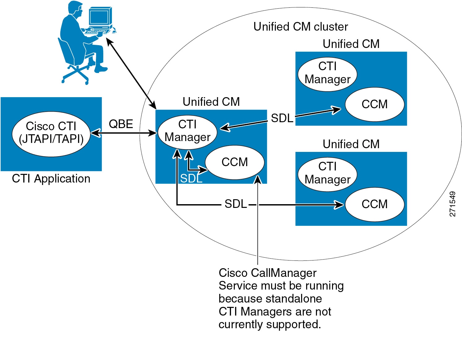
Once an application is authenticated and authorized, the CTIM acts as the broker between the telephony application and the Cisco CallManager Service. (This service is the call control agent and should not be confused with the overall product name Cisco Unified Communications Manager.) The CTIM responds to requests from telephony applications and converts them to Signaling Distribution Layer (SDL) messages used internally in the Unified CM system. Messages from the Cisco CallManager Service are also received by the CTIM and directed to the appropriate telephony application for processing.
The CTIM may be activated on any of the Unified CM subscriber nodes in a cluster that have the Cisco CallManager Service active. This allows up to eight CTIMs to be active within a Unified CM cluster. Standalone CTIMs are currently not supported.
CTI Applications and Clustering Over the WAN
Deployments that employ clustering over the WAN are supported in the following two scenarios:
- CTI Manager over the WAN (see Figure 9-10)
In this scenario, the CTI application and its associated CTI Manager are on one side of the WAN (Site 1), and the monitored or controlled devices are on the other side, registered to a Unified CM subscriber (Site 2). The round-trip time (RTT) must not exceed the currently supported limit of 80 ms for clustering over the WAN. To calculate the necessary bandwidth for CTI traffic, use the formula in the section on Local Failover Deployment Model. Note that this bandwidth is in addition to the Intra-Cluster Communication Signaling (ICCS) bandwidth calculated as described in the section on Local Failover Deployment Model, as well as any bandwidth required for audio (RTP traffic).
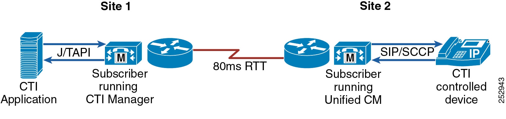
- TAPI and JTAPI applications over the WAN (CTI application over the WAN; see Figure 9-11)
In this scenario, the CTI application is on one side of the WAN (Site 1), and its associated CTI Manager is on the other side (Site 2). In this scenario, it is up to the CTI application developer or provider to ascertain whether or not their application can accommodate the RTT as implemented. In some cases failover and failback times might be higher than if the application is co-located with its CTI Manager. In those cases, the application developer or provider should provide guidance as to the behavior of their application under these conditions.
Figure 9-11 JTAPI Over the WAN
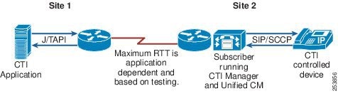
Note![]() Support for TAPI and JTAPI over the WAN is application dependent. Both customers and application developers or providers should ensure that their applications are compatible with any such deployment involving clustering over the WAN.
Support for TAPI and JTAPI over the WAN is application dependent. Both customers and application developers or providers should ensure that their applications are compatible with any such deployment involving clustering over the WAN.
Capacity Planning for CTI
The maximum number of supported CTI-controlled devices is 40,000 per cluster. For more information on CTI capacity planning, including per-platform node and cluster CTI capacities as well as CTI resource calculation formulas and examples, see the chapter on Collaboration Solution Sizing Guidance.
High Availability for CTI
This section provides some guidelines for provisioning CTI for high availability.
CTI Manager
CTI Manager must be enabled on at least one and possibly all call processing subscribers within the Unified CM cluster. The client-side interfaces (TAPI TSP or JTAPI client) allow for two IP addresses each, which then point to Unified CM server nodes running the CTIM service. For CTI application redundancy, Cisco recommends having the CTIM service activated on at least two Unified CM server nodes in a cluster, as shown in Figure 9-12.
Redundancy, Failover, and Load Balancing
For CTI applications that require redundancy, the TAPI TSP or JTAPI client can be configured with two IP addresses, thereby allowing an alternate CTI Manager to be used in the event of a failure. It should be noted that this redundancy is not stateful in that no information is shared and/or made available between the two CTI Managers, and therefore the CTI application will have some degree of re-initialization to go through, depending on the exact nature of the failover.
When a CTI Manager fails-over, just the CTI application login process is repeated on the now-active CTI Manager. Whereas, if the Unified CM server node itself fails, then the re-initialization process is longer due to the re-registration of all the devices from the failed Unified CM to the now-active Unified CM, followed by the CTI application login process.
For CTI applications that require load balancing or that could benefit from this configuration, the CTI application can simply connect to two CTI Managers simultaneously, as shown in Figure 9-12.
Figure 9-12 Redundancy and Load Balancing
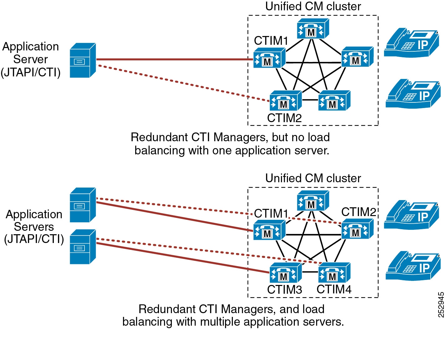
Figure 9-13 shows an example of this type of configuration for Cisco Unified Contact Center Enterprise (Unified CCE). This type of configuration has the following characteristics:
- Unified CCE uses two Peripheral Gateways (PGs) for redundancy.
- Each PG logs into a different CTI Manager.
- Only one PG is active at any one time.
Figure 9-13 CTI Redundancy with Cisco Unified Contact Center Enterprise
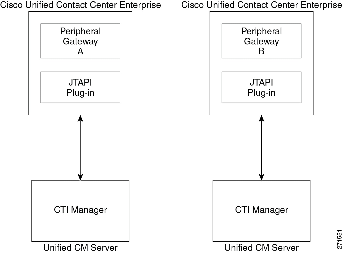
Figure 9-14 shows an example of this type of configuration for Cisco Unified Contact Center Express (Unified CCX). This type of configuration has the following characteristics:
- Unified CCX has two IP addresses configured, one for each CTI Manager.
- If connection to the primary CTI Manager is lost, Unified CCX fails-over to its secondary CTI Manager.
Figure 9-14 CTI Redundancy with Cisco Unified Contact Center Express
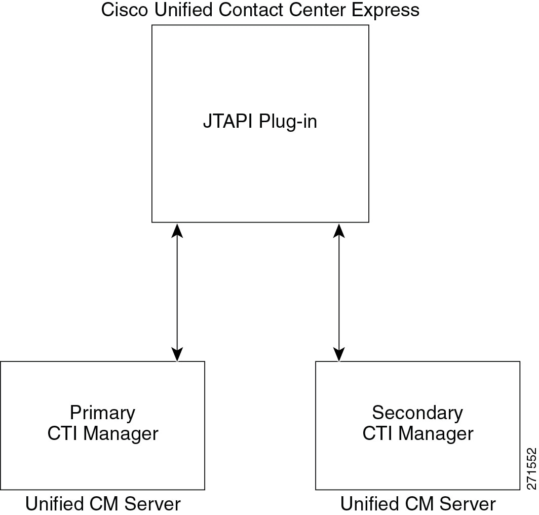
Implementation
For guidance and support on writing applications, application developers should consult the Cisco Developer Connection, located at
Integration of Multiple Call Processing Agents
To integrate multiple Unified CM clusters together or to integrate Unified CM clusters with the Cisco TelePresence Video Communication Server (VCS), use Cisco Unified CM Session Management Edition (SME). SME is the recommended trunk and dial plan aggregation platform in multi-site distributed call processing deployments. SME is essentially a Unified CM cluster with trunk interfaces only and no IP endpoints. It enables aggregation of multiple Unified Communications systems, referred to as leaf systems.
Unified CM Session Management Edition may also be used to connect to third-party unified communications systems such as PSTN connections, PBXs, and centralized unified communications applications.
For more information on SME, see the section on Unified CM Session Management Edition.
Direct integration of multiple call processing agents is also possible. The following sections explain the direct integration of Unified CM with Unified Communications Manager Express (CME) and integration of Unified CM with Cisco TelePresence VCS.
Interoperability of Unified CM and Unified CM Express
This section explains the requirements for interoperability and internetworking of Cisco Unified CM with Cisco Unified Communications Manager Express (Unified CME) using SIP trunking protocol in a multisite IP telephony deployment. This section highlights the recommended deployments between phones controlled by Unified CM and phones controlled by Unified CME.
This section covers the following topics:
- Overview of Interoperability Between Unified CM and Unified CME
- Unified CM and Unified CME Interoperability via SIP in a Multisite Deployment with Distributed Call Processing
Cisco Unified CM and Cisco Unified Communications Manager Express (Unified CME) could also be integrated using H.323, but this section does not cover this integration in detail. For more information on the H.323 integration, refer to the Cisco Collaboration 9.x SRND, available at
Overview of Interoperability Between Unified CM and Unified CME
Either H.323 or SIP can be used as a trunking protocol to interconnect Unified CM and Unified CME. When deploying Unified CM at the headquarters or central site in conjunction with one or more Unified CME systems for branch offices, network administrators must choose either the SIP or H.323 protocol after careful consideration of protocol specifics and supported features across the WAN trunk. Using H.323 trunks to connect Unified CM and Unified CME has been the predominant method in past years, until more enhanced capabilities for SIP phones and SIP trunks were added in Unified CM and Unified CME. This section first describes some of the features and capabilities that are independent of the trunking protocol for Unified CM and Unified CME interoperability, then it explains some of the most common design scenarios and best practices for using SIP trunks.
Call Types and Call Flows
In general, Unified CM and Unified CME interworking allows all combination of calls from SCCP IP phones to SIP IP phones, or vice versa, across a SIP trunk or H.323 trunk. Calls can be transferred (blind or consultative) or forwarded back and forth between the Unified CM and Unified CME SIP and/or SCCP IP phones.
When connected to Unified CM via H.323 trunks, Unified CME can auto-detect Unified CM calls. When a call terminating on Unified CME is transferred or forwarded, Unified CME regenerates the call and routes the call appropriately to another Unified CME or Unified CM by hairpinning the call. Unified CME hairpins the call legs from Unified CM for the VoIP calls across SIP or H.323 trunks when needed. For more information on allowing auto-detection on a non-H.450 supported Unified CM network and for enabling or disabling supplementary services for H450.2, H450.3, or SIP, refer to the Unified CME product documentation available at
http://www.cisco.com/en/US/products/sw/voicesw/ps4625/tsd_products_support_series_home.html
When connected to Unified CM via SIP trunks, Unified CME does not auto-detect Unified CM calls. By default, Unified CME always tries to redirect calls using either a SIP Refer message for call transfer or a SIP 302 Moved Temporarily message for call forward; if that fails, Unified CME will then try to hairpin the call.
Music on Hold
While Unified CM can be enabled to stream MoH in both G.711 and G.729 formats, Unified CME streams MoH only in G.711 format. Therefore, when Unified CME controls the MoH audio on a call placed on hold, it requires a transcoder to transcode between a G.711 MoH stream and a G.729 call leg.
Instant and Permanent Hardware Conferencing
Hardware DSP resources are required for both instant and permanent conferences. Whether connected via SIP, H.323, or PSTN, both Unified CM and Unified CME phones can be invited or added to an instant conference to become conference participants as along as the phones are reachable from the network. When calls are put on hold during an active conference session, music will not be heard by the conference participants in the conference session.
For information on required and supported DSP resources and the maximum number of conference participants allowed for instant or permanent conferences, refer to the Unified CME product documentation available at
http://www.cisco.com/en/US/products/sw/voicesw/ps4625/tsd_products_support_series_home.html
Unified CM and Unified CME Interoperability via SIP in a Multisite Deployment with Distributed Call Processing
Unified CM can communicate directly with Unified CME using a SIP interface. Figure 9-15 shows a Cisco Unified Communications multisite deployment with Unified CM networked directly with Cisco Unified CME using a SIP trunk.
Figure 9-15 Multisite Deployment with Unified CM and Unified CME Using SIP Trunks
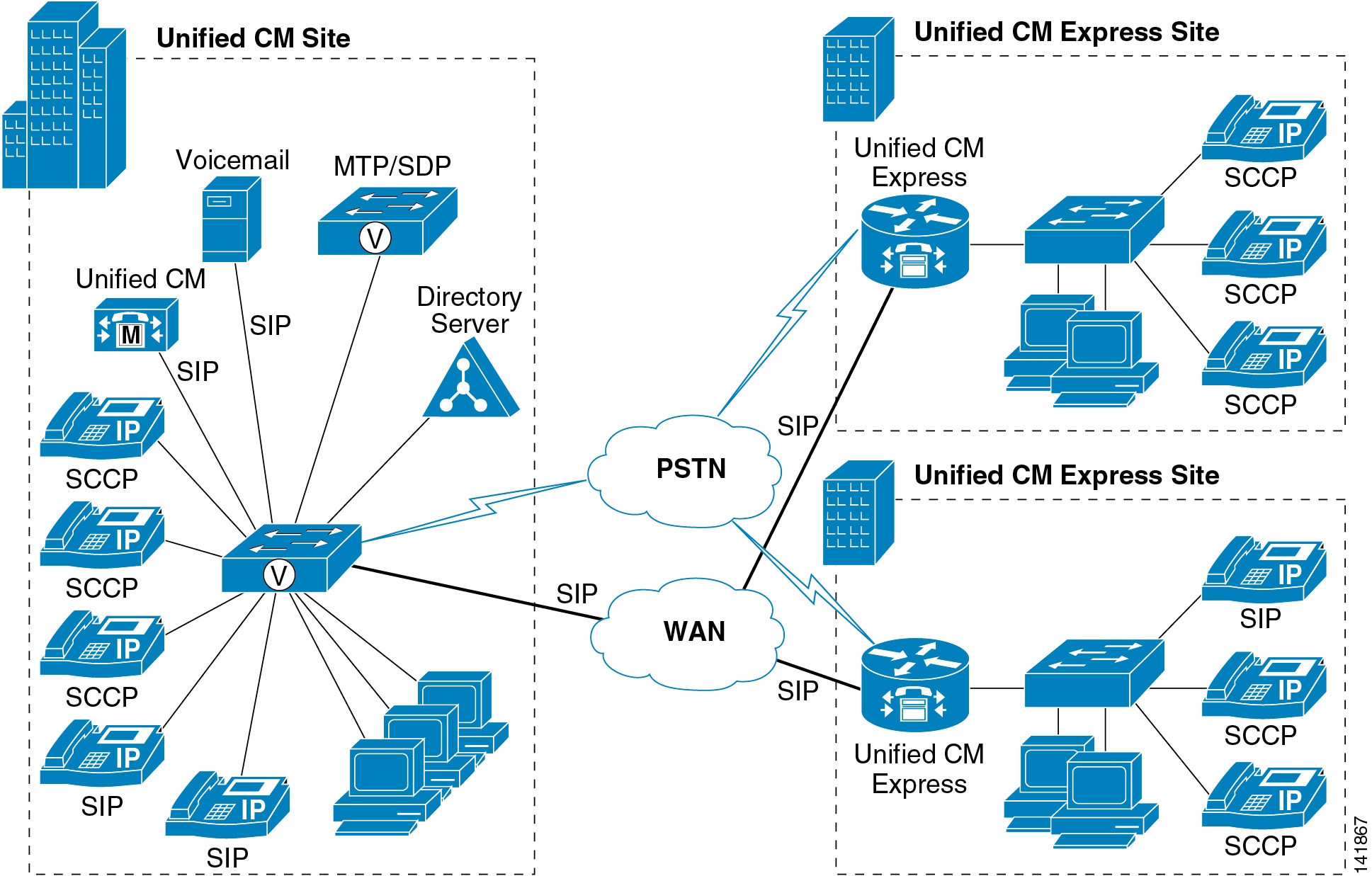
Best Practices
Follow these guidelines and best practices when using the deployment model illustrated in Figure 9-15:
- Configure a SIP Trunk Security Profile with Accept Replaces Header selected.
- Configure a SIP trunk on Unified CM using the SIP Trunk Security Profile created, and also specify a ReRouting CSS. The ReRouting CSS is used to determine where a SIP user (transferor) can refer another user (transferee) to a third user (transfer target) and which features a SIP user can invoke using the SIP 302 Redirection Response and INVITE with Replaces.
- For SIP trunks there is no need to enable the use of media termination points (MTPs) when using SCCP endpoints on Unified CME. However, SIP endpoints on Unified CME require the use of media termination points on Unified CM to be able to handle delayed offer/answer exchanges with the SIP protocol (that is, the reception of INVITEs with no Session Description Protocol).
- Route calls to Unified CME via a SIP trunk using the Unified CM dial plan configuration (route patterns, route lists, and route groups).
- Use Unified CM device pools and regions to configure a G.711 codec within the site and the G.729 codec for remote Unified CME sites.
- Configure the allow-connections sip to sip command under voice services voip on Unified CME to allow SIP-to-SIP call connections.
- For SIP endpoints, configure the mode cme command under voice register global, and configure dtmf-relay rtp-nte under the voice register pool commands for each SIP phone on Unified CME.
- For SCCP endpoints, configure the transfer-system full-consult command and the transfer-pattern.T command under telephony-service on Unified CME.
- Configure the SIP WAN interface voip dial-peers to forward or redirect calls, destined for Unified CM, with session protocol sipv2 and dtmf-relay [ sip-notify | rtp-nte ] on Unified CME.
Design Considerations
This section first covers some characteristics and design considerations for Unified CM and Unified CME interoperability via SIP in some main areas such as supplementary services for call transfer and forward, presence service for busy lamp field (BLF) notification for speed-dial buttons and directory call lists, and out-of-dialog (OOD-Refer) for integration with partner applications and third-party phone control for click-to-dial between the Unified CM phones and Unified CME phones. The section also covers some general design considerations for Unified CM and Unified CME interoperability via SIP.
SIP Refer or SIP 302 Moved Temporarily messages can be used for supplementary services such as call transfer or call forward on Unified CME or Unified CM to instruct the transferee (referee) or phone being forwarded (forwardee) to initiate a new call to the transfer-to (refer-to) target or forward-to target. No hairpinning is needed for call transfer or call forward scenarios when the SIP Refer or SIP 302 Moved Temporarily message is supported.
However, supplementary-service must be disabled if there are certain extensions that have no DID mapping or if Unified CM or Unified CME does not have a dial plan to route the call to the DID in the SIP 302 Moved Temporarily message. When supplementary-service is disabled, Unified CME hairpins the calls or sends a re-invite SIP message to Unified CM to replace the media path to the new called party ID. Both signaling and media are hairpinned, even when multiple Unified CMEs are involved for further call forwards. The supplementary-service can also be disabled for transferred calls. In this case, the SIP Refer message will not be sent to Unified CM, but the transferee (referee) party and transfer-to party (refer-to target) are hairpinned.
Note![]() Supplementary services can be disabled with the command no supplementary-service sip moved-temporarily or no supplementary-service sip refer under voice service voip or dial-peer voice xxxx voip.
Supplementary services can be disabled with the command no supplementary-service sip moved-temporarily or no supplementary-service sip refer under voice service voip or dial-peer voice xxxx voip.
The following examples illustrate the call flows when supplementary services are disabled:
- Unified CM phone B calls Unified CME phone A, which is set to call-forward (all, busy, or no answer) to phone C (either a Unified CM phone, a Unified CME phone on the same or different Unified CME, or a PSTN phone).
Unified CME does not send the SIP 302 Moved Temporarily message to Unified CM, but hairpins the call between Unified CM phone B and phone C.
- Unified CM phone B calls Unified CME phone A, which transfer the call to phone C (either a Unified CM phone, a Unified CME phone, or a PSTN phone).
Unified CME does not send the SIP Refer message to Unified CM, but hairpins the call between Unified CM phone B and phone C.
General Design Considerations for Unified CM and Unified CME Interoperability via SIP
- Disable supplementary-service if SIP 302 Moved Temporarily or SIP Refer messages are not supported by Unified CM, otherwise Unified CM cannot route the call to the transfer-to or forward-to target.
- In a SIP-to-SIP call scenario, a Refer message is sent by default from the transferor to the transferee, the transferee sets up a new call to the transfer-to target, and the transferor hears ringback tone by default while waiting for the transfer at connect. If supplementary-service is disabled on Unified CME, Unified CME will provide in-band ringback tone right after the call between the transferee and transfer-to target is connected.
- Presence service is supported on Unified CM and Unified CME via SIP trunk only.
- The OOD-Refer feature allows third-party applications to connect two endpoints on Unified CM or Unified CME through the use of the SIP REFER method. Consider the following factors when using OOD-Refer:
–![]() Both Unified CM and Unified CME must be configured to enable the OOD-Refer feature.
Both Unified CM and Unified CME must be configured to enable the OOD-Refer feature.
–![]() Call Hold, Transfer, and Conference are not supported during an OOD-Refer transaction, but they are not blocked by Unified CME.
Call Hold, Transfer, and Conference are not supported during an OOD-Refer transaction, but they are not blocked by Unified CME.
–![]() Call transfer is supported only after the OOD-Refer call is in the connected state and not before the call is connected; therefore, call transfer-at-alert is not supported.
Call transfer is supported only after the OOD-Refer call is in the connected state and not before the call is connected; therefore, call transfer-at-alert is not supported.
- Control signaling in TLS is supported, but SRTP is not supported over the SIP trunk.
- SRTP over a SIP trunk is a gateway feature in Cisco IOS for Unified CM. SRTP support is not available with Unified CM and Unified CME interworking via SIP trunks.
Note![]() When multiple PSTN connections exist (one for Unified CM and one for Unified CME), fully attended transfer between a Unified CM endpoint and a Unified CME endpoint to a PSTN endpoint will fail. The recommendation is to use blind transfer when using multiple PSTN connections, and it is configured under telephony-service as transfer-system full-blind.
When multiple PSTN connections exist (one for Unified CM and one for Unified CME), fully attended transfer between a Unified CM endpoint and a Unified CME endpoint to a PSTN endpoint will fail. The recommendation is to use blind transfer when using multiple PSTN connections, and it is configured under telephony-service as transfer-system full-blind.
Interoperability of Cisco TelePresence VCS with Unified CM
In a deployment with Unified CM as the main call processing agent, Cisco VCS can be added to provide full-featured interoperability with H.323 telepresence endpoints and interworking with SIP, integration with third-party video endpoints, and alternate solutions for telepresence conferencing. This section covers the integration of Unified CM with Cisco TelePresence VCS. It does not cover the integration of Unified CM with Cisco Expressway.
Note![]() To avoid the dial plan and call admission control complexities that dual call control introduces (see Design Considerations for Dual Call Control Deployments), Cisco recommends using SIP to register all TelePresence endpoints and room-based TelePresence conferencing systems to Cisco Unified Communications Manager.
To avoid the dial plan and call admission control complexities that dual call control introduces (see Design Considerations for Dual Call Control Deployments), Cisco recommends using SIP to register all TelePresence endpoints and room-based TelePresence conferencing systems to Cisco Unified Communications Manager.
Unified CM and VCS clusters are joined by one or more connections, called trunks in Unified CM and zones in VCS. A trunk or zone is the fundamental connection between two call processing agents in different clusters, exchanging signaling protocols and call routing information. Cisco recommends using the SIP protocol for the trunks and zones.
Figure 9-16 illustrates a Unified CM cluster connected to the VCS cluster with a SIP trunk.
Figure 9-16 Cisco Unified CM Integrated with Cisco VCS by Means of a SIP Trunk
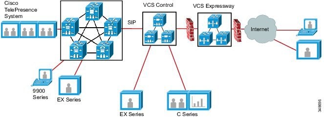
To integrate Unified CM with Cisco TelePresence VCS, on Unified CM configure a SIP trunk across an IP network. If the VCS has multiple VCS peers, you can use a DNS SRV record for the VCS cluster. Alternatively, you can specify a list of VCS peers in the SIP trunk configuration using the hostnames or IP addresses of the VCS peers. Also run the vcs-interop normalization script on the Unified CM SIP trunk configuration. For more information on this normalization script, refer to the latest version of the Cisco Unified Communications Manager System Guide, available at
http://www.cisco.com/en/US/products/sw/voicesw/ps556/prod_maintenance_guides_list.html
For more details on the Unified CM SIP trunk design, refer to the chapter on Cisco Unified CM Trunks.
On Cisco TelePresence VCS, to configure a connection to a cluster of Unified CM nodes, use any of the following methods:
- Configure a single neighbor zone in VCS, with the Unified CM nodes listed as location peer addresses.
- Use DNS SRV records and a Cisco VCS DNS zone.
- Set up multiple zones, one per Unified CM node. Then configure a set of prioritized search rules to route calls to each of the zones in the preferred order.
Cisco recommends the first and second configuration methods listed above because they ensure that the VCS-to-Unified CM call load is shared across Unified CM nodes. The third method provides only redundancy and not load balancing.
For more information, refer to the latest version of the Cisco TelePresence Video Communication Server Cisco Unified Communications Manager Deployment Guide, available at
http://www.cisco.com/en/US/products/ps11337/products_installation_and_configuration_guides_list.html
Dial Plan Integration
Dial plan integration between Unified CM and VCS is simpler if it is based on a numeric dial plan. Therefore, for new deployments, use a numeric dial plan across Unified CM and VCS whenever possible. However, in situations where a partially URI-based deployment already exists or is chosen for a new deployment, alphanumeric URIs can be used.
The simplest way to route directory URI calls from a supported endpoint on Unified CM to an endpoint on a Cisco TelePresence Video Communication Server (VCS) is to configure a domain-based SIP route pattern. For example, you can configure a SIP route pattern of cisco.com to route calls addressed to the cisco.com domain out a SIP trunk that is configured for the VCS.
When deploying multiple Unified CM clusters and VCS clusters using the same domain, configure Intercluster Lookup Service (ILS) to provide URI dialing interoperability. For each VCS, manually create a csv file with the directory URIs that are registered to that call control system. On a Unified CM cluster that is set up as a hub cluster in an ILS network and that could also be performing a Session Management Edition (SME) role, create an Imported directory URI catalog for each VCS, and assign a unique route string for each catalog. After you import the csv files into their corresponding imported directory URI catalog, ILS replicates the imported directory URI catalog and route string to the other clusters in the ILS network.
On each Unified CM cluster, configure SIP route patterns that match the route string assigned to each imported directory URI catalog in order to allow Unified CM to route directory URIs to an outbound trunk that is destined for the VCS.
For more information, refer to the latest version of the Cisco Unified Communications Manager System Guide, available at
http://www.cisco.com/en/US/products/sw/voicesw/ps556/prod_maintenance_guides_list.html
Design Considerations
- Both Unified CM and VCS can perform call admission control. However, bandwidth information is not exchanged between Unified CM and VCS.
- The integration between VCS and Unified CM clusters can also be done through Cisco Unified Communications Manager Session Management Edition (SME). For details, see the chapter on Collaboration Deployment Models.
- In general, Cisco recommends SIP Delayed Offer because no MTPs are required during call setup. SIP Early Offer using SIP Early Offer for Voice and Video (Insert MTP if needed) can also be used, but bear in mind that if an MTP is inserted, then only voice is supported during the initial call setup. For more information, see the chapter on Cisco Unified CM Trunks.
- The best practice for integrating dial plans between Unified CM and VCS clusters is to normalize the dial plan (with a flat domain, and separate and unique DN ranges) in either call agent through careful planning during the deployment and by using the following available mechanisms in the call processing applications:
–![]() Transforms and search rules on VCS
Transforms and search rules on VCS
–![]() Route patterns, translations, and transformation patterns in Unified CM
Route patterns, translations, and transformation patterns in Unified CM
 Feedback