-
Cisco Unified Communications SRND Based on Cisco Unified Communications Manager 5.x
-
Preface
-
Introduction
-
IP Telephony Deployment Models
-
Network Infrastructure
-
Gateways
-
Cisco Unified Communications Manager Trunks
-
Media Resources
-
Music on Hold
-
Call Processing
-
Call Admission Control
-
Dial Plan
-
Emergency Services
-
Third-Party Voicemail Design
-
Cisco Unity
-
Cisco Unified MeetingPlace Integration
-
Cisco Unified MeetingPlace Express
-
IP Video Telephony
-
LDAP Directory Integration
-
IP Telephony Migration Options
-
Voice Security
-
IP Telephony Endpoints
-
Cisco Unified Presence
-
Cisco Unified Communications Manager Applications
-
Cisco Mobility Applications
-
Recommended Hardware and Software Combinations
-
Glossary
-
Index
-
Table Of Contents
A Comparison of H.323 and SIP Trunks
IP PSTN and IP Trunks to Service Provider Networks
Intercluster Trunk (Non-Gatekeeper Controlled)
Intercluster Trunk (Gatekeeper Controlled)
H.225 Trunk (Gatekeeper Controlled)
Gatekeeper Trunk Redundancy, Resilience, and Load Balancing
H.323 Trunks with Media Termination Points
H323 Outbound FastStart Call Connections
General Deployment Considerations:
SIP Delayed Offer and Early Offer
Cisco Unified CM Trunks
Cisco Unified Communications Manager (Unified CM, formerly Cisco Unified CallManager) Release 4.0 introduced support for Session Initiation Protocol (SIP) trunks; prior to Release 4.0, Unified CM supported only H.323 trunks. This chapter discusses design considerations for Cisco Unified CM releases 5.x, but much of the discussion also applies to Unified CM releases 4.x and 3.3.
A Comparison of H.323 and SIP Trunks
Cisco Unified CM trunk connections support both H.323 and SIP. In many cases, the decision to use H.323 or SIP is driven by the unique feature(s) offered by each protocol. There are also a number of external factors that can affect the choice of trunk protocol, such as customer preference or the protocol's maturity and degree of interoperability offered between various vendors' products.
For trunk connections between Cisco devices, this decision is relatively straightforward. For trunk connections to other vendors' products and to service provider networks, it is important to understand which features are required by the customer and the extent of interoperability between any two vendors' products.
Table 5-1 compares some of the features offered over H.323 and SIP trunks between Unified CM clusters.
Overview of H.323 Trunks
The H.323 trunk provides connectivity to other Unified CM clusters and other H.323 devices such as gateways. H.323 trunks support most of the audio and video codecs that Unified CM supports for intracluster communications, with the exception of wideband audio, wideband video, and H.264 video.
H.323 trunks use the Empty Capabilities Set (ECS) to provide supplementary call services such as hold/resume and transfer. This method is a standard H.245 mechanism to stop or close a media stream (or channel) and start or open it to the same or a different endpoint address. This method allows Unified CM to keep a call active while still being able to control the source and destination of the media streams on the fly.
For example, consider a call between two clusters (A and B) using the H.323 trunk. When a user in cluster A places a user in cluster B on hold, the media streams between the two users are closed and the user in cluster B is connected to a music on hold (MoH) server in cluster A. The MoH server is instructed to send media (the music file) to the user. When the user in cluster A resumes the call, the MoH stream is closed and the two-way media streams are reopened between the two users. (Unified CM does not support H.450 for supplementary call services.) In this case, MoH is an example of an ECS operation. H.323 trunks do not support multicast MoH, therefore the media resource group list (MRGL) for the H.323 trunks must contain only unicast MoH sources. (For details, see Music on Hold.)
The bandwidth used for calls on H.323 trunks can be controlled by the use of regions configured in Unified CM and assigned to each trunk. A region limits the amount of bandwidth allocated for calls by specifying the audio codec type and video bandwidth per call for that region. Calls between that region and another region must be within the specified bandwidth limit. If the device making the call over the H.323 trunk is in a more restrictive region or does not support a particular codec such as video, then it is a subset of codecs that are allowed for that call.
All dual tone multifrequency (DTMF) signaling on an H.323 trunk is provided out-of-band using H.245.
Overview of SIP Trunks
SIP trunks provide connectivity to other SIP devices such as gateways, proxies, voicemail systems, and other Unified CM clusters. Cisco Unified CM 5.x and 6.0 introduced major enhancements for SIP trunks and removed the limitations in Cisco Unified CM 4.1 and 4.0, such as single codec support, lack of video support, and the mandatory media termination point (MTP) for RFC 2833 DTMF support.
The main enhancements to SIP trunks in Cisco Unified CM 6.0 are the support for the iLBC and AAC codecs and SIP PUBLISH. By providing improved performance, SIP PUBLISH provides the preferred mechanism for Cisco Unified CM 6.0 to send IP phone presence information to Cisco Unified Presence over a SIP trunk.
For the complete list of new enhancements for SIP trunks, refer to the Cisco Unified Communications Manager product release notes available at
http://www.cisco.com/en/US/products/sw/voicesw/ps556/prod_release_notes_list.html
When used for intercluster trunking, SIP trunks do not support Secure Real-Time Transport Protocol (SRTP) or QSIG Tunneling using Annex M1.
IP PSTN and IP Trunks to Service Provider Networks
With support for both H.323 and SIP trunks in Cisco Unified CM, service providers are starting to offer non-TDM PSTN connections to enterprise customers. Apart from the obvious benefit of the cost savings from deploying non-TDM interfaces, in many case these IP-based PSTN connections also offer additional voice features over traditional PSTN interfaces.
The choice of H.323 or SIP as the IP trunking protocol often depends on the service provider, although today the majority of IP-based PSTN connections are likely to use H.323 because of its relative maturity and greater number of proven deployments when compared with SIP. However, because SIP offers additional capabilities such as Presence and support for many multimedia applications (such as instant messaging), SIP will probably become the more widely deployed Unified Communications protocol in the long term.
Because both the SIP and H323 standard are open to a degree of interpretation (there are many optional as well as mandatory requirements), the degree of interoperability between vendors is often something that improves over time as the protocols mature. To this end, the Cisco Unified Border Element (formerly the IP-to-IP Gateway) offers a number of interoperability features as well as a natural demarcation point as a Session Border Controller when connecting to other vendors' H323 and SIP networks.
Cisco Unified Border Element
The Cisco Unified Border Element product provides a wide range of signalling and media functionality between the enterprise and service-provider Cisco Unified Communications networks. Cisco Unified Border Element provides a network-to-network interface point for:
•
Address and port translations (privacy and topology hiding)
•
•
•
•
The Cisco Unified Border Element is a licensed Cisco IOS application that is available on the Cisco 2800 and 3800 Series Integrated Service Routers (ISR), the Cisco AS5350XM and AS5400XM Media Gateways, and the Cisco 7200VXR and Cisco 7301 Series router and gateway platforms.
Cisco recommends the use of Cisco Unified Border Element for any IP PSTN deployment.
H.323 Trunks
The following major types of H.323 trunks can be configured in a Unified CM:
•
•
•
Intercluster Trunk (Non-Gatekeeper Controlled)
This trunk is the simplest and is used for connecting to other Unified CM clusters in either a multi-cluster single campus or a distributed call processing deployment. This trunk does not use a gatekeeper for call admission control, although it may use locations configured in Unified CM if bandwidth control is required.
When defining this type of trunk, you may define up to three remote Unified CM servers in the same destination cluster. The trunk will automatically load-balance across all defined remote Unified CM servers. In the remote cluster, it is important to configure a corresponding intercluster trunk (non-gatekeeper controlled) that has a Unified CM Group containing the same servers that were defined as remote Unified CM servers in the first cluster. A similar configuration is required in each Unified CM cluster connected by the intercluster trunks.
For example, if Cluster 1 has a trunk to Cluster 2 and Cluster 2 has a trunk to Cluster 1, the following configurations would be needed:
•
–
–
•
–
–
Intercluster Trunk (Gatekeeper Controlled)
The intercluster gatekeeper controlled trunk should be used instead of the non-gatekeeper controlled trunk for a larger number of clusters. The advantages of using the gatekeeper controlled trunk are mainly the overall administration of the cluster and failover times. Non-gatekeeper controlled trunks generally require that a full mesh of trunks be configured, which can become an administrative burden as the number of clusters increases. In addition, if a subscriber server in a cluster becomes unreachable, there will be a 5-second (default) timeout while the call is attempted. If an entire cluster is unreachable, the number of attempts before either call failure or rerouting over the PSTN will depend on the number of remote servers defined for the trunk and on the number of trunks in the route list or route group. If there are many remote servers and many non-gatekeeper controlled trunks, the call delay can become excessive.
With a gatekeeper controlled trunk, you configure only one trunk that can then communicate via the gatekeeper with all other clusters registered to the gatekeeper. If a cluster or subscriber becomes unreachable, the gatekeeper automatically directs the call to another subscriber in the cluster or rejects the call if no other possibilities exist, thus allowing the call to be rerouted over the PSTN (if required) with little incurred delay. With a single Cisco gatekeeper, it is possible to have 100 clusters all registering a single trunk each, with all clusters being able to call each other. With non-gatekeeper controlled trunks, this same topology would require 99 trunks configured in each cluster. The gatekeeper controlled intercluster trunk should be used for communicating only with other Unified CMs because the use of this trunk with other H.323 devices might cause problems with supplementary services. In addition, a gatekeeper controlled intercluster trunk must be used for backward compatibility with Unified CM prior to Release 3.2.
H.225 Trunk (Gatekeeper Controlled)
The H.225 gatekeeper controlled trunk is essentially the same as the intercluster gatekeeper controlled trunk except that it has the capability of working with Unified CM clusters (Release 3.2 and later) as well as other H.323 devices such as gateways, conferencing systems, and clients. This capability is achieved through a discovery mechanism on a call-by-call basis. (See H.323 Operation in Unified CM, for details of this discovery process.) This type of trunk is the recommended H.323 trunk if all Unified CM clusters are at least Release 3.2.
Gatekeeper Trunk Redundancy, Resilience, and Load Balancing
Redundancy can be achieved in several ways, depending on the requirements of the design. The simplest method is to configure a gatekeeper controlled trunk and assign up to three subscribers in the Unified CM Group associated with the device pool assigned to that trunk. This configuration will cause all servers to register with the same gatekeeper in the same zone with the same technology prefix. However, the H.323 trunk name that is used for the h323_id will have a suffix of "_n" where n is the node number in the cluster. This ID is automatically generated and cannot be changed. You configure a single trunk, but the gatekeeper registers multiple trunks, one from each subscriber in the Unified CM Group.
If you have additional redundancy requirements, it is possible to configure another gatekeeper controlled trunk with a different name and different subscribers in the Unified CM Group, but with all the other parameters identical to the first trunk. This second trunk will cause additional subscribers to register with the gatekeeper.
Cisco recommends assigning device pools that contain a Unified CM Group consisting of the two servers that make up the standard subscriber pair. (See Call Processing Subscriber, for more information on subscriber redundancy.) For complete redundancy in each full cluster, four trunks would be needed, using four different device pools and resulting in eight subscribers registering with the gatekeeper. (The same result could be achieved with three trunks and larger Unified CM Groups.)
During registration, several parameters are passed between Unified CM and the gatekeeper. Unified CM uses an ephemeral User Datagram Protocol (UDP) port for gatekeeper Registration Admission Status (RAS) messages. This port would normally be UDP 1719. However, Unified CM must be able to identify precisely which H.323 daemon is the originator of a RAS message from a particular server; therefore it uses a range of UDP ports and assigns them dynamically.
During the registration process, a trunk registers the following information for the other subscribers in its Unified CM Group:
•
•
•
•
•
If the recommended clustered gatekeepers are used, the gatekeeper will return a list of alternate gatekeeper addresses that may be used if the primary gatekeeper fails or does not have sufficient available resources.
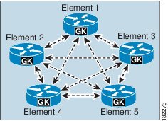
Figure 5-1 shows a cluster of gatekeepers that use Gatekeeper Update Protocol (GUP) to communicate. (See the chapter on Call Processing, for more information on gatekeepers.)
Figure 5-1 Gatekeeper Cluster
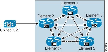
If an H.323 trunk has only a single subscriber in its Unified CM Group, there will be only one connection between the configured gatekeeper in Unified CM and the gatekeeper cluster, as illustrated in Figure 5-2.
Figure 5-2 H.323 Trunk with a Single Unified CM Subscriber
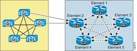
If there are multiple subscribers in the Unified CM Group associated with the trunk, additional connections will be established between the Unified CM cluster and the gatekeeper cluster, as illustrated in Figure 5-3.
Figure 5-3 H.323 Trunk with Multiple Unified CM Subscribers
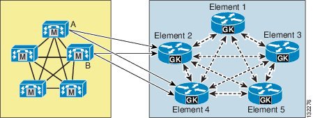
This approach provides redundancy for subscriber failures as well as gatekeeper failures after registration because the alternate gatekeeper is communicated when the trunk registers. This approach does not, however, provide redundancy if the configured gatekeeper is unavailable at initial registration or following a reset because the list of alternate gatekeepers is dynamic and not stored in the database. To provide an additional level of redundancy as well as load balancing, an additional gatekeeper from the gatekeeper cluster is configured in Unified CM. For example, if the original trunk is registered with Element 2, the additional gatekeeper could be configured as Element 4, as illustrated in Figure 5-4.
Figure 5-4 Additional Gatekeeper Configured for Load Balancing and Additional Redundancy
The Unified CM configuration for the example in Figure 5-4 would contain the following components:
•
•
Using this approach, the Unified CM cluster will still be able to register when either Element 2 or Element 4 is not reachable during initial registration (that is, during power-up or trunk reset).
Load balancing of calls inbound to the Unified CM cluster is done automatic by default because the gatekeeper randomly selects one of the subscribers registered within the zone. If this is not the desired behavior, you can use the gw-priority configuration command in the gatekeeper to modify this default behavior, as illustrated in Example 5-1.
Example 5-1 Using the gw-priority Command to Direct Calls to a Particular Trunk
gatekeeperzone local SJC cisco.com 10.0.1.10zone prefix SJC 1408....... gw-priority 10 sjc-trunk_2zone prefix SJC 1408....... gw-priority 9 sjc-trunk_3zone prefix SJC 1408....... gw-default-priority 0gw-type-prefix 1#* default-technologyarq reject-unknown-prefixno shutdownendpoint ttl 60In Example 5-1, the H.323 trunk was configured as sjc-trunk in Unified CM, and the "_2" and "_3" suffixes are appended automatically by the Unified CM subscribers to indicate which node number they are in the cluster. Therefore, this example uses node 2 as the first choice, which should be the highest-priority Unified CM in the Unified CM Group for this trunk. Node 3 is the second choice in this case.
The use of gw-default-priority 0 is optional. It was used in this example to disable the use of any other trunk that might accidentally be configured to register in this zone.
Load-Balancing Outbound Calls
In the majority of cases, the standard method of assigning Unified CM Groups to devices is sufficient to handle the call distribution of outbound calls over IP trunks from call processing subscribers. IP trunk calls might appear to originate randomly from call processing subscribers, but the trade-off for this random call origination is reduced call processing and reduced Intra-Cluster Communication Signaling (ICCS) traffic within the cluster. Load balancing of outbound IP trunk calls across call processing servers, as described below, can be counter-productive because the advantages gained from predictable call origination within the cluster can be outweighed by the increase in ICCS traffic created by calls from phones registered to one subscriber extending their communication to another server within the cluster to originate the outgoing IP trunk call.
For the initiation of outbound calls over an H.323 trunk, the following key factors within a Unified CM cluster determine which server is selected:
•
•
For IP trunks, the server selection process is not as intuitive as it is for H.323 connections to gateways where, for example, route lists and route groups can be used to select the gateway(s) used to originate the call to the PSTN and also to provide call distribution among multiple gateways. While the route list and route group process still operates for trunk selection and call distribution, a second process is also in operation to select the server from which the H.323 call will originate. In other words, after the route list and route group configuration selects the outgoing trunk, one server in the Unified CM Group for the selected trunk must be chosen to originate the H.323 call.
For all IP trunks, this process of server selection for outgoing calls is as follows:
•
•
Note
To provide predictable and deterministic load balancing for outgoing calls over IP trunks, you must consider the trunk selection behavior described above.
Subscriber-based load balancing of outgoing IP trunk calls can be achieved as follows:
•
•
For example, to spread outbound trunk calls across four subscribers in the cluster, perform the following tasks:
•
•
–
–
–
–
With no backup subscribers defined, if the primary subscriber for the specified trunk fails, Unified CM will re-route outgoing calls to the next trunk in the route group.
In the example above, backup subscribers can be defined within each Unified CM Group for each trunk provided, using subscribers A, B, C, and D as follows:
•
•
•
•
However, to avoid subscriber selection for outgoing trunk calls based on phone registration and H.323 daemon subscriber co-location, all phones in the cluster should be registered to other call processing servers (for example, subscribers E, F, G, and H), with server redundancy as required using Unified CM Groups.
To spread outbound trunk calls across all eight subscribers in a cluster, perform the flowering tasks:
•
•
–
–
–
–
–
–
–
–
H.323 Trunks with Media Termination Points
Media termination points (MTPs) are generally not required for normal operation of the H.323 trunk. They are, however, required for communication with devices that are H.323 Version 1, that do not support the Empty Capabilities Set (ECS) for supplementary services, or that require H323 FastStart.
To test whether or not an MTP is required, use the following simple procedure:
1.
2.
H323 Outbound FastStart Call Connections
Calls that are placed from IP phones over large WAN topologies can experience voice clipping when the called party goes off-hook to answer the call. When H.323 trunks or gateways are separated from the Unified CM server, significant delays can occur because of the many H.245 messages that are exchanged when a call is set up.
With the FastStart feature, information that is required to complete a media connection between two parties gets exchanged during the H.225 portion of call setup, and this exchange eliminates the need for H.245 messages. The connection experiences one round-trip WAN delay during call setup, and the calling party does not experience voice clipping when the called party answers the call.
Unified CM uses media termination points (MTP) for making an H.323 outbound FastStart call. Unified CM starts an outbound FastStart call by allocating an MTP and opening the receive channel. Next, the H.323 Fast Connect procedure sends the SETUP message with a FastStart element to the called endpoint. The FastStart element includes information about the receiving channel for the MTP.
Other MTP Uses
MTPs are very useful for terminating media streams from other devices that make calls over the H.323 trunk and for re-originating the media streams with the same voice payload; however, in such cases the IP address is changed to that of the MTP. With this fact in mind, you can utilize MTPs in the following scenarios:
•
•
With both of these methods, if the MTP Required box is checked, the default behavior is to allow calls on the H.323 trunks even if MTP resources are unavailable or exhausted. This default behavior might result in no voice path for the call, but the behavior can be changed by setting the Unified CM service parameter Fail Call if MTP allocation fails under the H.323 section to True.
H.323 Operation in Unified CM
This section provides information on how the H.323 protocol is used and implemented in Unified CM, and it explains how and why certain features work the way they do.
The most important point to understand is which subscribers run the call signaling daemons. These daemons are pieces of code that make and receive H.323 calls. They are usually referred to as H.225 daemons, or H.225Ds. H.225 is part of the H.323 protocol and is mainly responsible for call control. H.245 is the other major component of H.323 that is responsible for the media control of a call.
The subscribers listed in the Unified CM Group for a particular H.323 device determine which subscribers run the daemons and when. This point is a very important because calls sent to an incorrect subscriber might be rejected. For example, this situation would occur if a Cisco IOS H.323 gateway is configured with dial peers that send calls to subscriber C in a Unified CM cluster but the Unified CM Group for that gateway has only subscribers A and B in its list. In such a case, the call will fail or be handled by an H.323 trunk daemon if one happens to be configured on the subscriber.
The following scenarios describe where and when H.225Ds are created on subscribers:
•
The H.225D is active on only the highest-priority subscriber available in the Unified CM Group associated with the H.323 client.
If the H.323 client is gatekeeper controlled, the RasAggregator device registers from only the highest-priority subscriber available in the Unified CM Group associated with the gatekeeper controlled H.323 client.
The RasAggregator is a special device that registers in gatekeeper zones for the purpose of providing two specific features:
–
–
•
The H.225D is active on all subscribers in the Unified CM Group associated with the H.323 gateway.
•
The H.225D is active on all subscribers in the Unified CM Group associated with the H.323 trunk. A RAS daemon registers the trunk with the gatekeeper from all subscribers in the associated Unified CM Group.
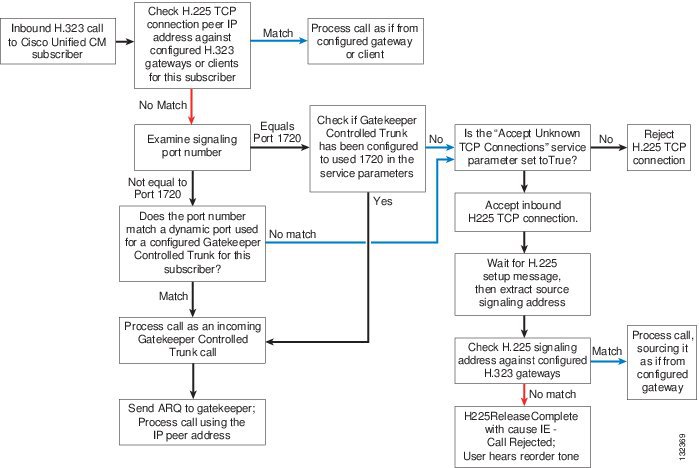
When an incoming H.323 call is made to a subscriber in a Unified CM cluster, various decisions are made to determine if the call is accepted or rejected and which H.225D will receive the call if it is accepted. Figure 5-5 shows how this process works.
Figure 5-5 Process for Determining if an H.323 Call is Accepted or Rejected
Unified CM H.323 protocol includes the following additional features:
•
This feature provides the ability to determine, on a call-by-call basis, if the calling device is from Cisco Unified CM Release 3.2 or later. Whenever a call is received, Unified CM looks for an H.225 User-to-User Information Element (UUIE) that indicates if the other end is another Unified CM. If it is, it will always use the Intercluster Trunk Protocol. If no UUIE is found, it will use the configured protocol for that device. This feature enables an H.225 gatekeeper controlled trunk to switch between Intercluster Trunk Protocol and H.225 on a call-by-call basis, allowing a mixture of Unified CM clusters and other H.323 devices to use the gatekeeper. Intercluster Trunk Protocol is the same as H.225 except for several differences that enable specific features to work correctly between Unified CM clusters.
•
With the release of Cisco Unified CM 4.1(3), this feature can be enabled on all H.323 trunks. It allows specific H.323 Annex M1 features to be implemented between Unified CM clusters and other verified systems that also support H.323 Annex M1. These features include:
–
–
–
•
When registering with a gatekeeper that supports this feature, such as a Cisco Multimedia Conference Manager (MCM) Gatekeeper, Unified CM can inform the gatekeeper of alternate destinations for calls to the H.323 trunk. These alternate endpoints or destinations are sent to the calling device by the gatekeeper when this H.323 trunk is called. They are the other subscribers listed in the Unified CM Group associated with the H.323 trunk that registers with the gatekeeper.
•
When an H.323 trunk registers with a gatekeeper that supports this feature (for example, a Cisco gatekeeper cluster), Unified CM is dynamically informed about other gatekeepers that can process registrations, call admission requests, and other RAS functions in the event that this gatekeeper fails or exhausts its own resources.
•
When an H.323 trunk sends an admission request (ARQ) to the gatekeeper, it might receive a different E.164 number in the admission confirmation message (ACF), indicating that the original called number should be replaced with this new one. This feature requires a route server using Gatekeeper Transaction Message Protocol (GKTMP) to communicate with Cisco gatekeepers.
Note
•
H.323 trunks can update the gatekeeper with bandwidth information to indicate a change in the requested bandwidth allocated to a specific call. This feature is disabled by default and is controlled by setting the Unified CM service parameter BRQ Enabled to True, under the H.323 section. This feature is especially important when video is used on an H.323 trunk because the original bandwidth request is for the maximum amount allowed. Enabling this feature ensures that call admission control uses the actual bandwidth negotiated during call setup.
SIP Trunks
As with H.323 trunks, there are several design considerations to be taken into account when deploying SIP trunks. This section describes those design considerations.
General Deployment Considerations:
For SIP trunk connections to third-party devices, such as SIP-based PBXs or service-provider IP PSTN connections, Cisco recommends the use of Delayed Offer for outbound calls from Unified CM and either Delayed Offer or Early Offer for inbound calls to Unified CM. Using Delayed Offer for outbound calls removes the requirement to assign MTP resources to the SIP trunk, except in cases where a mismatch in DTMF transport types exists between the called and calling endpoints (in which case Unified CM will insert an MTP dynamically).
As previously mentioned, Cisco also recommends the deployment of the Cisco Unified Border Element on any IP PSTN SIP trunk connection from Unified CM to a voice service provider.
For DTMF over Unified CM SIP trunks, RFC 2833 is the recommended DTMF transport method.
SIP Delayed Offer, Early Offer, and DTMF are discussed in more detail in the subsequent sections.
DTMF Transport
There are several methods of transporting DTMF information between SIP endpoints. In general terms, these methods can be classified as out-of-band (OOB) and in-band signaling. In-band DTMF transport methods send either raw or signaled DTMF tones within the RTP stream, and they need to be handled and interpreted by the endpoints that generate and/or receive them. Out-of-band (OOB) signaling methods transport DTMF tones outside of the RTP path, either directly to and from the endpoints or via a call agent such as Cisco Unified CM, which interprets and/or forwards these tones as required.
Out-of-band (OOB) SIP DTMF signaling methods include Unsolicited Notify (UN), Information (INFO), and Key Press Markup Language (KPML). While KPML (RFC 4730) is the OOB signaling method preferred by Cisco, KPML is not widely used in the market place at this time. Currently, the only known products supporting KPML are Cisco Unified CM, Cisco IOS Gateways (Release 12.4 and later), and some models of Cisco IP Phones. Unsolicited Notify is a nonstandard method and is used only on Cisco IOS Gateways (Release 12.2 and later). INFO is not supported by Unified CM.
In-band DTMF transport methods send DTMF tones as either raw tones in the RTP media stream or as signaled tones in the RTP payload using RFC 2833. Among SIP product vendors, RFC 2833 has become the predominant method of sending and receiving DTMF tones and is supported by the majority of Cisco voice products.
Because in-band signaling methods send DTMF tones in the RTP media stream, the SIP endpoints in a session must either support the transport method used (for example, RFC 2833) or provide a method of intercepting this in-band signaling and converting it. If the two endpoints are using a back-to-back user agent (B2BUA) server for the call control (for example, Cisco Unified CM) and the endpoints negotiate different DTMF methods between each device and call control box, then the call control box determines how to handle the DTMF differences, either via MTP insertion or via OOB methods. With Unified CM, a DTMF transport mismatch (for example, in-band to out-of-band DTMF) is resolved by inserting a Media Termination Point (MTP), which terminates the RTP stream with in-band DTMF signaling (RFC 2833), extracts the DTMF tones from the RTP stream, and forwards these tones out-of-band to Unified CM, where they are then forwarded to the endpoint supporting out-of-band signaling. In this case, the MTP is always in the media path between the two endpoints because there is no MTP codec dependency for DTMF translation.
In-band DTMF tones can also be transported as raw (audible) tones in the RTP media stream. This transport method is not widely supported by Cisco products and, in general, is not recommended as an end-to-end DTMF transport mechanism. In-band audio DTMF tones can generally be reproduced reliably only when using G.711 a-law or mu-law codecs, and they are not suitable for use with low-bandwidth codecs. In cases where in-band audio is the only available DTMF transport mechanism, the Cisco Unified Border Element can be used to translate the in-band audio DTMF signaling into RFC 2833 signaling.
SIP Delayed Offer and Early Offer
Cisco Unified CM uses the SIP Offer/Answer model for establishing SIP sessions, as defined in RFC 3264. In this context, an Offer is contained in the Session Description Protocol (SDP) fields sent in the body of a SIP message. The Offer typically defines the media characteristics supported by the device (media streams, codecs, directional attributes, IP address, and ports to use). The device receiving the Offer sends an Answer in the SDP fields of its SIP response, with its corresponding matching media streams and codec, whether accepted or not, and the IP address and port on which it wants to receive the media streams. Unified CM uses this Offer/Answer model to establish SIP sessions as defined in the key SIP standard, RFC 3261.
RFC 3261 defines two ways that SDP messages can be sent in the Offer and Answer. These methods are commonly known as Delayed Offer and Early Offer, and support for both methods by User Agent Client/Servers is a mandatory requirement of the specification. In the simplest terms, an initial SIP Invite sent with SDP in the message body defines an Early Offer, whereas an initial SIP Invite without SDP in the message body defines a Delayed Offer.
In an Early Offer, the session initiator (calling device) sends its capabilities (for example, codecs supported) in the SDP contained in the initial Invite (thus allowing the called device to choose its preferred codec for the session). In a Delayed Offer, the session initiator does not send its capabilities in the initial Invite but waits for the called device to send its capabilities first (for example, the list of codecs supported by the called device, thus allowing the calling device to choose the codec to be used for the session).
Delayed Offer and Early Offer are the two media capabilities exchange options available to all standards-based SIP switches. Most vendors have a preference for either Delayed Offer or Early Offer, each of which has its own set of benefits and limitations.
Note
Early Media
In certain circumstances, a SIP session might require that a media path be set up prior to the finalization of the media capabilities exchange between the two SIP endpoints. To this end, the SIP protocol allows the establishment of Early Media after the initial Offer has been received by an endpoint. Some reasons for using Early Media include:
•
•
Unified CM supports Early Media for both Early Offer and Delayed Offer calls.
Note
Media Termination Points
Media Termination Points (MTPs) are generally not required for Delayed Offer calls from Unified CM SIP trunks. For this reason, Cisco recommends Delayed Offer as the call setup method for outbound calls from Unified CM SIP trunks. For outbound Early Offer calls from Unified CM, MTP resources are required (SIP Trunk MTP required box is checked) and remain in the media path for the duration of the call.
For calls inbound and outbound from Unified CM, endpoints can negotiate the use of RFC 2833 or an out-of-band DTMF method (for example, KPML) end-to-end. If a common DTMF method cannot be negotiated between the endpoints, Cisco Unified CM 5.x and later releases will insert an MTP dynamically. Cisco Unified CM 5.x and later releases support Delayed Offer (Invite without SDP) by default. Although Delayed Offer is a mandatory part of the SIP RFC 3261 specification, some SIP applications do not support it. In those cases, you must configure the SIP trunk to support Early Offer by pre-allocating an MTP under the SIP Trunk configuration.
MTPs are available in three forms:
•
•
•
The following example configuration is for a Cisco IOS software-based MTP:
!sccp local Vlan5sccp ccm 10.10.5.1 identifier 5 version 5.0.1! Communications Manager IP address (10.10.5.1)sccp!sccp ccm group 5bind interface Vlan5associate ccm 5 priority 1associate profile 5 register MTP000E83783C50! MTP name (MTP000E83783C50) ... must match the Unified CM MTP name.!dspfarm profile 5 mtpdescription software MTPcodec g711ulawcodec pass-throughmaximum sessions software 500associate application SCCPFor more information on MTPs, see the chapter on Media Resources.
SIP Trunk Transport Protocols
SIP trunks can use either TCP or UDP as a message transport protocol. As a reliable, connection-orientated protocol that maintains the connection state, TCP is preferred because failover to an alternative trunk is nearly instantaneous on the failure of the destination device at the far end of the SIP trunk. UDP is not connection-orientated and therefore relies on the SIP protocol stack to determine if the destination device at the end of the SIP trunk is unavailable. For UDP-based SIP trunks, Unified CM uses the values for the SIP Invite Retry count and SIP Trying timers to detect and respond to far-end device failures. By default, the failover time is approximately 64 seconds per call, but these timers can be tuned to reduce failover times to acceptable values.
For more information on SIP trunk timer tuning, refer to the configuration example and technical notes at:
SIP Intercluster Trunks
One of the main benefits of using SIP trunks for intercluster trunking is call survivability. However, as compared to H.323 trunks, SIP trunks do not support Secure Real-Time Transport Protocol (SRTP) or QSIG Tunneling using Annex M1. For outbound calls over SIP trunks using destination IP addresses rather than DNS, subscriber load balancing can be achieved in the same way as for H.323 trunk calls. (See the H.323 section on Load-Balancing Outbound Calls.)
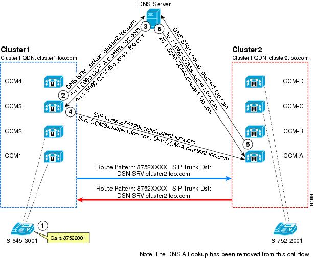
Unlike H.323 trunks in Cisco Unified CM Release 3.3 and above, SIP trunks can point to only a single IP address or DNS Server (SRV) record. To provide failover and load balancing for intercluster SIP trunks that are not capable of DNS SRV, configure multiple SIP trunks. In addition, these SIP trunks must be members of route groups and route lists. Also, it is important to note that Unified CM accepts calls only from a SIP device whose IP address matches one of the destination addresses of the configured SIP trunks. In addition, the incoming port number of the SIP messages has to match the port number configured for that SIP trunk. As a consequence, Cisco recommends that you configure as many SIP trunks with destination addresses as needed to match all IP addresses of any far-end SIP devices that can potentially place an inbound call. This method is not desirable for deployments with more than two Unified CM clusters, and it is better to use SIP trunks with DNS SRV if there are more than two clusters. Figure 5-6 shows the call flow for an intercluster SIP trunk call using DNS SRV.
Figure 5-6 Call Flow for Intercluster SIP Trunk Using DNS SRV
Figure 5-6 illustrates the following steps in the call flow:
1.
2.
3.
4.
5.
6.