-
Cisco Unified Communications SRND Based on Cisco Unified Communications Manager 5.x
-
Preface
-
Introduction
-
IP Telephony Deployment Models
-
Network Infrastructure
-
Gateways
-
Cisco Unified Communications Manager Trunks
-
Media Resources
-
Music on Hold
-
Call Processing
-
Call Admission Control
-
Dial Plan
-
Emergency Services
-
Third-Party Voicemail Design
-
Cisco Unity
-
Cisco Unified MeetingPlace Integration
-
Cisco Unified MeetingPlace Express
-
IP Video Telephony
-
LDAP Directory Integration
-
IP Telephony Migration Options
-
Voice Security
-
IP Telephony Endpoints
-
Cisco Unified Presence
-
Cisco Unified Communications Manager Applications
-
Cisco Mobility Applications
-
Recommended Hardware and Software Combinations
-
Glossary
-
Index
-
Table Of Contents
Co-resident and Standalone MoH
Fixed and Audio File MoH Sources
MoH Server as Part of the Unified CM Cluster
Unicast and Multicast MoH Call Flows
MoH Configuration Considerations and Best Practices
Using Multiple Fixed (Live) Audio Sources
Unicast and Multicast in the Same Unified CM Cluster
Hardware and Capacity Planning for MoH Resources
Resource Provisioning and Capacity Planning
Implications for MoH With Regard to IP Telephony Deployment Models
Single-Site Campus (Relevant to All Deployments)
Centralized Multisite Deployments
Call Admission Control and MoH
Multicast MoH from Branch Routers
Distributed Multisite Deployments
Detailed Unicast and Multicast MoH Call Flows
Music on Hold
Music on hold (MoH) is an integral feature of the Cisco Unified Communications system. This feature provides music to callers when their call is placed on hold, transferred, parked, or added to an ad-hoc conference. Implementing MoH is relatively simple but requires a basic understanding of unicast and multicast traffic, MoH call flows, configuration options, server behavior and requirements. This chapter describes how to design and provision MoH resources for a Cisco Enterprise IP Telephony deployment.
Cisco Unified Communications Manager (Unified CM) provides access to a variety of media resources. A media resource is a software-based or hardware-based entity that performs some media processing function on the voice data streams that are connected to it. Media processing functions include mixing multiple streams to create one output stream, passing the stream from one connection to another, or transcoding the data stream from one compression type to another.
Unified CM allocates and uses the following types of media resources:
•
Media termination point (MTP) resources
•
•
•
•
For more information about media resources in general, see the chapter on Media Resources.
This chapter examines the following design aspects of the MoH feature:
•
•
•
•
Deployment Basics of MoH
For callers to hear music on hold, Unified CM must be configured to support the MoH feature. The MoH feature has two main requirements:
•
•
The integrated MoH feature allows users to place on-net and off-net users on hold with music streamed from a streaming source. This source makes music available to any on-net or off-net device placed on hold. On-net devices include station devices and applications placed on hold, consult hold, or park hold by an interactive voice response (IVR) or call distributor. Off-net users include those connected through Media Gateway Control Protocol (MGCP), Session Initiation Protocol (SIP), and H.323 gateways. The MoH feature is also available for plain old telephone service (POTS) phones connected to the Cisco IP network through Foreign Exchange Station (FXS) ports. The integrated MoH feature includes media server, database administration, call control, media resource manager, and media control functional areas. The MoH server provides the music resources and streams.
You can configure the MoH feature via the Unified CM Administration interface. When an end device or feature places a call on hold, Unified CM connects the held device to an MoH media resource. Essentially, Unified CM instructs the end device to establish a connection to the MoH server. When the held device is retrieved, it disconnects from the MoH resource and resumes normal activity.
Unicast and Multicast MoH
Unified CM supports two types of MoH transport mechanisms:
•
•
Unicast MoH consists of streams sent directly from the MoH server to the endpoint requesting an MoH audio stream. A unicast MoH stream is a point-to-point, one-way audio Real-Time Transport Protocol (RTP) stream between the server and the endpoint device. Unicast MoH uses a separate source stream for each user or connection. As more endpoint devices go on hold via a user or network event, the number of MoH streams increases. Thus, if twenty devices are on hold, then twenty streams of RTP traffic are generated over the network between the server and these endpoint devices. These additional MoH streams can potentially have a negative effect on network throughput and bandwidth. However, unicast MoH can be extremely useful in those networks where multicast is not enabled or where devices are not capable of multicast, thereby still allowing an administrator to take advantage of the MoH feature.
Multicast MoH consists of streams sent from the MoH server to a multicast group IP address that endpoints requesting an MoH audio stream can join as needed. A multicast MoH stream is a point-to-multipoint, one-way audio RTP stream between the MoH server and the multicast group IP address. Multicast music on hold conserves system resources and bandwidth because it enables multiple users to use the same audio source stream to provide music on hold. Thus, if twenty devices are on hold, then potentially only a single stream of RTP traffic is generated over the network. For this reason, multicast is an extremely attractive technology for the deployment of a service such as MoH because it greatly reduces the CPU impact on the source device and also greatly reduces the bandwidth consumption for delivery over common paths. However, multicast MoH can be problematic in situations where a network is not enabled for multicast or where the endpoint devices are not capable of handling multicast.
For information about IP multicast network design, refer to the IP Multicast SRND document, available online at
Recommended Unicast/Multicast Gateways
The following recommended gateways support both unicast and multicast MoH:
•
•
•
Co-resident and Standalone MoH
The MoH feature requires the use of a server that is part of a Unified CM cluster. You can configure the MoH server in either of the following ways:
•
In a co-resident deployment, the MoH feature runs on any server (either publisher or subscriber) in the cluster that is also running the Unified CM software.
Note
•
A standalone deployment places the MoH feature on a dedicated server within the Unified CM cluster. The sole function of this dedicated server is to send MoH streams to devices within the network.
Fixed and Audio File MoH Sources
You can set up the source for MoH in any of the following ways:
•
–
–
•
–
–
MoH can be generated from an audio file stored on the MoH server. Audio files must be in one of the following formats:
•
•
•
MoH audio files are generated automatically by Unified CM when .wav formatted audio files are uploaded to the MoH server using the upload file function on the MoH Audio File Management page (or on the Music On Hold Audio Source Configuration page). Unified CM then transcodes and formats audio source files into the appropriate MoH source files for the specified codec type(s). When an MoH event occurs, the MoH server streams the configured audio source file to the requesting device on hold.
Note
If recorded or live audio is needed, MoH can be generated from a fixed source. For this type of MoH, a sound card is required. The fixed audio source is connected to the audio input of the local sound card.
This mechanism enables you to use radios, CD players, or any other compatible sound source. The stream from the fixed audio source is transcoded in real-time to support the codec that was configured through Unified CM Administration. The fixed audio source can be transcoded into G.711 (A-law or mu-law), G.729 Annex A, and Wideband, and it is the only audio source that is transcoded in real-time.
The Cisco MoH USB audio sound card (MOH-USB-AUDIO=) must be used for connecting a fixed or live audio source to the MoH server. This USB sound card is compatible with all MCS platforms supporting Cisco Unified CM Release 5.x.
Note
MoH Server as Part of the Unified CM Cluster
The MoH feature requires that each MoH server must be part of a Unified CM cluster. All MoH servers must share their configurations with the publisher server and participate in the database replication schema. Specifically, the MoH server must share the following information (configured through Unified CM Administration) by means of the database:
•
•
•
The MoH server becomes part of the Unified CM cluster and participates in the database replication automatically. To configure a standalone MoH server, start with a normal Unified CM installation on that server, then disable the Cisco CallManager Service (on the standalone MoH server only) and enable the Cisco IP Voice Media Streaming Application.
Basic MoH and MoH Call Flows
This section describes the basic operation of MoH as implemented in Unified CM, as well as typical call flow scenarios.
Basic MoH
The basic operation of MoH in a Cisco Unified Communications environment consists of a holder and a holdee. The holder is the endpoint user or network application placing a call on hold, and the holdee is the endpoint user or device placed on hold.
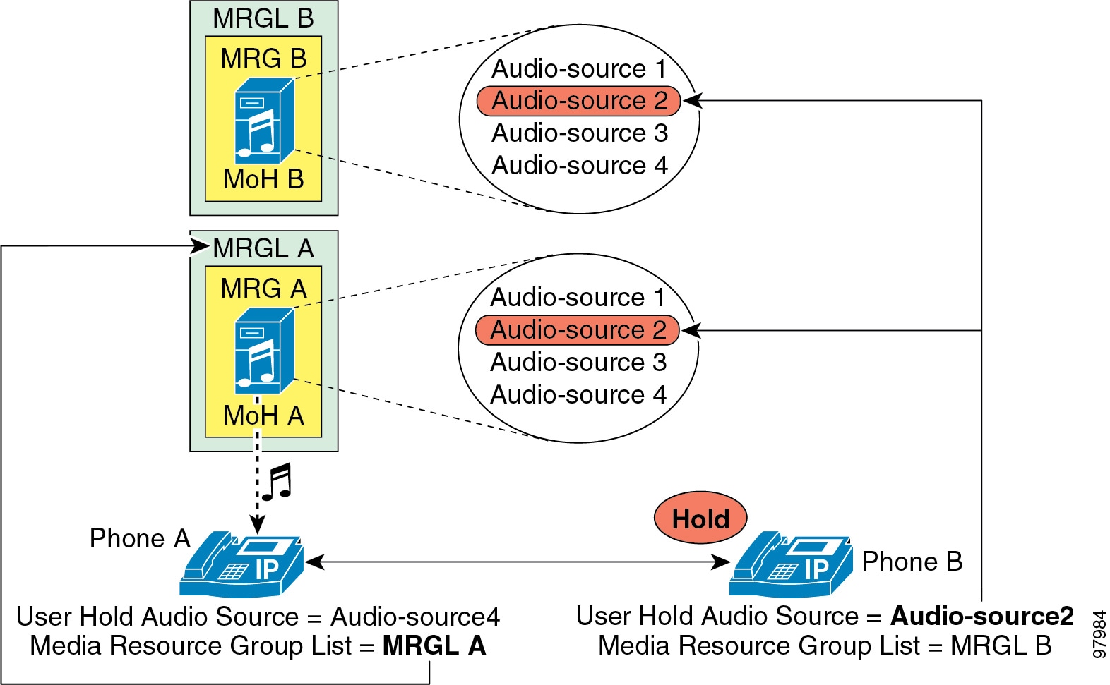
The MoH stream that an endpoint receives is determined by a combination of the User Hold MoH Audio Source of the device placing the endpoint on hold (holder) and the configured media resource group list (MRGL) of the endpoint placed on hold (holdee). The User Hold MoH Audio Source configured for the holder determines the audio file that will be streamed when the holder puts a call on hold, and the holdee's configured MRGL indicates the resource or server from which the holdee will receive the MoH stream.
In simplest terms, the holder's configuration determines which audio file to play, and the holdee's configuration determines which resource or server will play that file. As illustrated by the example in Figure 7-1, if phones A and B are on a call and phone B (holder) places phone A (holdee) on hold, phone A will hear the MoH audio source configured for phone B (Audio-source2). However, phone A will receive this MoH audio stream from the MRGL (resource or server) configured for phone A (MRGL A).
Figure 7-1 User Hold Audio Source and Media Resource Group List (MRGL)
Because the configured MRGL determines the server from which a unicast-only device will receive the MoH stream, you must configure unicast-only devices with an MRGL that points to a unicast MoH resource or media resource group (MRG). Likewise, a device capable of multicast should be configured with an MRGL that points to a multicast MRG.
MoH Configuration Settings
You can configure the settings for MRGLs and User and Network Hold Audio Sources in several places within Unified CM Administration, and you can configure different (and potentially conflicting) settings in each place.
To determine which User and Network Audio Source configuration setting to apply in a particular case, Unified CM interprets these settings for the holder device in the following priority order:
1.
2.
3.
4.
When attempting to determine the audio source for a particular holder, Unified CM first looks at the User (or Network) Audio Source configured at the directory or line level. If this level is not defined, Unified CM looks at the User (or Network) Audio Source configured on the holder device. If this level is not defined, Unified CM looks at the User (or Network) Audio Source configured for the device pool of the holder device. If this level is not defined, then Unified CM looks at the cluster-wide default audio source ID configured under the Unified CM system parameters. (By default, this audio source ID is set to 1 for both User and Network Hold Audio Sources, which is the SampleAudioSource.)
Unified CM also interprets the MRGL configuration settings of the holdee device in the following priority order:
1.
2.
3.
When attempting to determine the MRGL for a particular holdee, Unified CM looks at the MRGL configured at the device level. If this level is not defined, Unified CM looks at the MRGL configured for the device pool of the holdee device. If this level is not defined, then Unified CM uses the system default MoH resources. System default MoH resources are those resources not assigned to any MRG, and they are always unicast.
User and Network Hold
There are two basic types of user hold:
•
•
Figure 7-2 shows these two types of call flows. If phone A is in a call with phone B and phone A (holder) pushes the Hold softkey, then a music stream is sent from the MoH server to phone B (holdee). The music stream can be sent to holdees within the IP network or holdees on the PSTN, as is the case if phone A places phone C on hold. In the case of phone C, the MoH stream is sent to the voice gateway interface and converted to the appropriate format for the PSTN phone. When phone A presses the Resume softkey, the holdee (phone B or C) disconnects from the music stream and reconnects to phone A.
Figure 7-2 Basic User Hold Example
Network hold includes the following types:
•
•
•
•
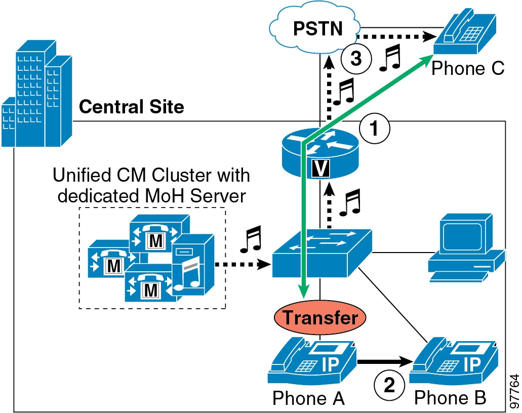
Figure 7-3 shows the call transfer call flow. When phone A receives a call from PSTN phone C (step 1), phone A answers the call and then transfers it to phone B (step 2). During the transfer process, phone C receives an MoH stream from the MoH server via the gateway (step 3). After phone A completes the transfer action, phone C disconnects from the music stream and gets redirected to phone B, the transfer destination. This process is the same for other network hold operations such as call park and conference setup.
Figure 7-3 Basic Network Hold Example for Call Transfer
Unicast and Multicast MoH Call Flows
MoH operation is quite similar to normal phone call flows, with the MoH server acting as an endpoint device to which the holdee device can connect or disconnect as required. However, there are distinct differences between unicast and multicast MoH call flow behavior. A unicast MoH call flow is initiated by a message from Unified CM to the MoH server. This message tells the MoH server to send an audio stream to the holdee device's IP address. On the other hand, a multicast MoH call flow is initiated by a message from Unified CM to the holdee device. This message instructs the endpoint device to join the multicast group address of the configured multicast MoH audio stream.
For a detailed look at MoH call flows, see the section on Detailed Unicast and Multicast MoH Call Flows.
MoH Configuration Considerations and Best Practices
This section highlights some MoH configuration considerations and best practice to help you design a robust MoH solution.
Codec Selection
If you need multiple codecs for MoH deployment, configure them in the IP Voice Streaming Media App service parameter under Unified CM Service Parameters Configuration. Select the desired codec types from the Supported MoH Codecs list under the Clusterwide Parameters section. By default, only G.711 mu-law is selected. To select another codec type, click on it in the scrollable list. For multiple selections, hold down the CTRL key and use the mouse to select multiple codecs from the scrollable list. After making your selection, click the Update button.
Note
Multicast Addressing
Proper IP addressing is important for configuring multicast MoH. Addresses for IP multicast range from 224.0.1.0 to 239.255.255.255. The Internet Assigned Numbers Authority (IANA), however, assigns addresses in the range 224.0.1.0 to 238.255.255.255 for public multicast applications. Cisco strongly discourages using public multicast addresses for music on hold. Instead, Cisco recommends that you configure multicast MoH audio sources to use IP addresses in the range 239.1.1.1 to 239.255.255.255, which is reserved for administratively controlled applications on private networks.
Furthermore, you should configure multicast audio sources to increment on the IP address and not the port number, for the following reasons:
•
Cisco IP phones have no concept of multicast port numbers. Therefore, if all the configured codecs for a particular audio stream transmit to the same multicast IP address (even on different port numbers), all streams will be sent to the IP phone even though only one stream is needed. This has the potential of saturating the network with unnecessary traffic because the IP phone is capable of receiving only a single MoH stream.
•
Routers have no concept of multicast port numbers. Thus, when it encounters multiple streams sent to the same multicast group address (even on different port numbers), the router forwards all streams of the multicast group. Because only one stream is needed, network bandwidth is over-utilized and network congestion can eventually result.
MoH Audio Sources
Configured audio sources are shared among all MoH servers in the Unified CM cluster, requiring each audio source file to be uploaded to every MoH server within the cluster. You can configure up to 51 unique audio sources per cluster (50 audio file sources and one fixed/live source via a sound card). For methods of providing additional sources, refer to the sections on Using Multiple Fixed (Live) Audio Sources, and Multicast MoH from Branch Routers.
For those audio sources that will be used for multicast streaming, ensure that Allow Multicasting and Play continuously (repeat) are enabled. If continuous play of an audio source is not specified, only the first party placed on hold, not additional parties, will receive the MoH audio source.
Using Multiple Fixed (Live) Audio Sources
It is important to remember that only a single fixed audio source can be configured within Unified CM. However, each MoH server in the Unified CM cluster is capable of streaming a single fixed audio source via a Cisco MoH USB audio sound card (MOH-USB-AUDIO). When multiple fixed audio sources are needed, additional MoH servers can be added to provide these multiple sources. The audio supplied to each MoH server sound card can be the same or different, and the administrator can determine which MoH server is selected based on MRG and MRGL selections. When multiple audio sources are done in this manner, the holder's User/Network Hold MoH Audio Source should be configured for the fixed audio source (the single fixed audio source that is configured in Unified CM), and the MoH server to stream that fixed audio source to the device is then determined by the MRGL of the holdee.
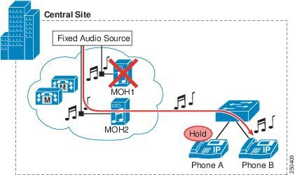
In the case where the audio source is the same, this method also allows for redundancy of the fixed audio source. For example, in Figure 7-4 there are two MoH servers, each with an MOH-USB-AUDIO sound card connected to an audio source streaming audio derived from a live radio station feed. Phone B's MRGL contains first an MRG that contains the MOH1 server and second an MRG that contains the MOH2 server. Assuming the User/Network Hold Audio Source at Phone A has been set to the fixed audio source, after a call is established between Phone A and Phone B, and Phone B is placed on hold by Phone A, Phone B will receive the live feed audio source from the MOH1 server. In the case where the MOH1 server is down (or has no available capacity) when Phone A puts Phone B on hold, Phone B will receive the live feed audio source from the MOH2 server.
Figure 7-4 Fixed Audio Source Redundancy Example
Note
Unicast and Multicast in the Same Unified CM Cluster
In some cases, administrators might want to configure a single Unified CM cluster to handle both unicast and multicast MoH streams. This configuration might be necessary because the telephony network contains devices or endpoint that do not support multicast or because some portions of the network are not enabled for multicast.
Use one of the following methods to enable a cluster to support both unicast and multicast MoH audio streams:
•
•
In either case, you must configure at least two MRGs and at least two media resource group lists (MRGLs). Configure one unicast MRG and one unicast MRGL for those endpoints requiring unicast MoH. Likewise, configure one multicast MRG and one multicast MRGL for those endpoints requiring multicast MoH.
When deploying separate MoH servers, configure one server without multicast enabled (unicast-only) and configure a second MoH server with multicast enabled. Assign the unicast-only MoH media resource and the multicast-enabled MoH media resource to the unicast and multicast MRGs, respectively. Ensure that the Use Multicast for MoH Audio box is checked for the multicast MRG but not for the unicast MRG. Also assign these unicast and multicast MRGs to their respective MRGLs. In this case, an MoH stream is unicast or multicast based on whether the MRG is configured to use multicast and then on the server from which it is served.
When deploying a single MoH server for both unicast and multicast MoH, configure the server for multicast. Assign this same MoH media resource to both the unicast MRG and the multicast MRG, and check the Use Multicast for MoH Audio box for the multicast MRG. In this case, an MoH stream is unicast or multicast based solely on whether the MRG is configured to use multicast.
Note
In addition, you must configure individual devices or device pools to use the appropriate MRGL. You can place all unicast devices in a device pool or pools and configure those device pools to use the unicast MRGL. Likewise, you can place all multicast devices in a device pool or pools and configure those device pools to use the multicast MRGL. Optionally, you can configure individual devices to use the appropriate unicast or multicast MRGL. Lastly, configure a User Hold Audio Source and Network Hold Audio Source for each individual device or (in the case of phone devices) individual lines or directory numbers to assign the appropriate audio source to stream.
When choosing a method for deploying both multicast and unicast MoH in the same cluster, an important factor to consider is the number of servers required. When using a single MoH server for both unicast and multicast, fewer MoH servers are required throughout the cluster. Deploying separate multicast and unicast MoH servers will obviously require more servers within the cluster.
Redundancy
Cisco recommends that you configure and deploy multiple MoH servers for completely redundant MoH operation. If the first MoH server fails or becomes unavailable because it no longer has the resources required to service requests, the second server can provide continued MoH functionality. For proper redundant configuration, assign resources from at least two MoH servers to each MRG in the cluster.
In environments where both multicast and unicast MoH are required, be sure to provide redundancy for both transport types to ensure MoH redundancy for all endpoints in the network.
Quality of Service (QoS)
Convergence of data and voice on a single network requires adequate QoS to ensure that time-sensitive and critical real-time applications such as voice are not delayed or dropped. To ensure proper QoS for voice traffic, the streams must be marked, classified, and queued as they enter and traverse the network to give the voice streams preferential treatment over less critical traffic. MoH servers automatically mark audio stream traffic the same as voice bearer traffic, with a Differentiated Services Code Point (DSCP) value of 46 or a Per Hop Behavior (PHB) value of EF (ToS of 0xB8). Therefore, as long as QoS is properly configured on the network, MoH streams will receive the same classification and priority queueing treatment as voice RTP media traffic.
Call signaling traffic between MoH servers and Unified CM servers is automatically marked with a DSCP value of 24 or a PHB value of CS3 (ToS of 0x60) by default. Therefore, as long as QoS is properly configured on the network, this call signalling traffic will be properly classified and queued within the network along with all other call signalling traffic.
Hardware and Capacity Planning for MoH Resources
As with all media resources, capacity planning is crucial to make certain that the hardware, once deployed and configured, can support the anticipated call volume of the network. For this reason, it is important to be aware of the hardware capacity for MoH resources and to consider the implications of multicast and unicast MoH in relation to this capacity.
Server Platform Limits
Table 7-1 lists the server platforms and the maximum number of simultaneous MoH sessions each can support. Ensure that network call volumes do not exceed these limits because, once MoH sessions have reached these limits, additional load could result in poor MoH quality, erratic MoH operation, or even loss of MoH functionality.
Table 7-1 Maximum Number of MoH Sessions per Server Platform Type
MCS 7815
MCS 7825G.711 (A-law and mu-law)
G.729a
Wideband audioCo-resident or standalone server:
250 MoH sessions1
MCS 7835
MCS 7845G.711 (A-law and mu-law)
G.729a
Wideband audioCo-resident or standalone server:
500 MoH sessions
1 You can configure a maximum of 51 unique audio sources per Unified CM cluster.
The following MoH Server Configuration parameters affect MoH server capacity:
•
This parameter determines the number of devices that can be placed on unicast MoH. By default this value is set to 250.
The Maximum Half Duplex Streams parameter should be set to the value derived from the following formula:
(Server and deployment capacity) - ((Number of multicast MoH sources) * (Number of MoH codecs enabled))
For example:
MCS-7835 standalone MoH server
Multicast MoH audio sources
MoH codecs enabled (G.711 mu-law and G.729)
Maximum half-duplex streams
500
- (12
* 2)
= 476
Therefore, in this example, the Maximum Half Duplex Streams parameter would be configured with a value of no more than 476.
The value of this parameter should never be set higher than the capacities indicated in Table 7-1, based on the platform and deployment type (co-resident or standalone).
•
This parameter determines the number of devices that can be placed on multicast MoH. By default this value is set to 30.
The Maximum Multicast Connections parameter should be set to a number that ensures that all devices can be placed on multicast MoH if necessary. Although the MoH server can generate only a finite number of multicast streams (maximum of 204), large numbers of held devices can join each multicast stream, thus it is necessary to set this parameter to an artificially large number. Typically multicast traffic is accounted for based on the number of streams being generated; however, Unified CM maintains a count of the actual number of devices placed on multicast MoH or joined to each multicast MoH stream. This method is different than the way multicast traffic is normally tracked.
Note
Failure to configure these parameters properly could lead to under-utilization of MoH server resources or failure of the server to handle the network load.
Note
Resource Provisioning and Capacity Planning
When provisioning for co-resident or standalone MoH server configurations, network administrators should consider the type of transport mechanism used for the MoH audio streams. If using unicast MoH, each device on hold will require a separate MoH stream. However, if using multicast MoH and only a single audio source, then only a single MoH stream is required for each configured codec type, no matter how many devices of that type are on hold.
For example, given a cluster with 30,000 phones and a 2% hold rate (only 2% of all endpoint devices are on hold at any given time), 600 MoH streams or sessions would be required. Given a unicast-only MoH environment, two co-resident (or standalone) MoH servers would be required to handle this load, as shown by the following calculation:
[(500 sessions per MCS 7835 or 7845 co-resident server) * (1 co-resident server)] + [(250 sessions per MCS 7815 or 7825 co-resident server) * (1 co-resident server)] > 600 sessions
By comparison, a multicast-only MoH environment with 36 unique MoH audio streams, for example, would require only one co-resident MoH server (MCS 7815 or 7825), as shown by the following calculation:
(250 sessions per MCS 7815 or 7825 co-resident server) * (1 co-resident server) > 36 sessions
These 36 unique multicast streams could be provisioned in any one of the following ways:
•
•
•
•
As these examples show, multicast MoH can provide a considerable savings in server resources over unicast MoH.
In the preceding examples, the 2% hold rate is based on 30,000 phones and does not take into account gateways or other endpoint devices in the network that are also capable of being placed on hold. You should consider these other devices when calculating a hold rate because they could potentially be placed on hold just as the phones can.
The preceding calculations also do not provide for MoH server redundancy. If an MoH server fails or if more than 2% of the users go on hold at the same time, there are no other MoH resources in this scenario to handle the overflow or additional load. Your MoH resource calculations should include enough extra capacity to provide for redundancy.
Implications for MoH With Regard to IP Telephony Deployment Models
The various IP Telephony deployment models introduce additional considerations for MoH configuration design. Which deployment model you choose can also affect your decisions about MoH transport mechanisms (unicast or multicast), resource provisioning, and codecs. This section discusses these issues in relation to the various deployment models.
For more detailed information about the deployment models, see the chapter on Deployment Models.
Single-Site Campus (Relevant to All Deployments)
Single-site campus deployments are typically based on a LAN infrastructure and provide sufficient bandwidth for large amounts of traffic. Because bandwidth is typically not limited in a LAN infrastructure, Cisco recommends the use of the G.711 (A-law or mu-law) codec for all MoH audio streams in a single-site deployment. G.711 provides the optimal voice and music streaming quality in an IP Telephony environment.
MoH server redundancy should also be considered. In the event that an MoH server becomes overloaded or is unavailable, configuring multiple MoH servers and assigning them in preferred order to MRGs ensures that another server can take over and provide the MoH streams.
With the increasing diversity of network technologies, in a large single-site campus it is likely that some endpoint devices will be unable to support multicast. For this reason, you might have to deploy both unicast and multicast MoH resources. For example, wireless IP phones do not support multicast due to the behavior of wireless technology. Thus, when deploying wireless IP phones, you have to configure both multicast and unicast MoH.
To ensure that off-net calls and application-handled calls receive expected MoH streams when placed on hold, configure all gateways and other devices with the appropriate MRGLs and audio sources, or assign them to appropriate device pools.
Centralized Multisite Deployments
Multisite IP telephony deployments with centralized call processing typically contain WAN connections to multiple non-central sites. These WAN links usually cause bandwidth and throughput bottlenecks. To minimize bandwidth consumption on these links, Cisco recommends the use of the G.729 codec for all MoH audio streams traversing the WAN. Because the G.729 codec is optimized for voice and not music applications, you should use G.729 only across the WAN, where the bandwidth savings far outweighs the lower quality afforded by G.729 for MoH transport. Likewise, because multicast traffic provides significant bandwidth savings, you should always use multicast MoH when streaming audio to endpoints across the WAN.
If the sound quality of an MoH stream becomes an issue when using the G.729 codec across the WAN, you can use the G.711 codec for MoH audio streams across the WAN while still using G.729 for voice calls. In order to send MoH streams across the WAN with the G.711 codec but voice calls across the WAN with the G.729 codec, place all MoH servers in a Unified CM region by themselves, and configure that region to use G.711 between itself and all other regions. Thus, when a call is placed between two phones on either side of a WAN, the G.729 codec is used between their respective regions. However, when the call is placed on hold by either party, the MoH audio stream is encoded using G.711 because G.711 is the configured codec to use between the MoH server's region and the region of the phone placed on hold.
Call Admission Control and MoH
Call admission control (CAC) is required when IP telephony traffic is traveling across WAN links. Due to the limited bandwidth available on these links, it is highly probable that voice media traffic might get delayed or dropped without appropriate call admission control. For additional information, see Call Admission Control.
Call admission control for Unified CM (based on either static locations or RSVP-enabled locations) is capable of tracking unicast MoH streams traversing the WAN but not multicast MoH streams. Thus, even if WAN bandwidth has been fully subscribed, a multicast MoH stream will not be denied access to the WAN by call admission control. Instead, the stream will be sent across the WAN, likely resulting in poor audio stream quality and poor quality on all other calls traversing the WAN. To ensure that multicast MoH streams do not cause this over-subscription situation, you should over-provision the QoS configuration on all downstream WAN interfaces by configuring the low-latency queuing (LLQ) voice priority queue with additional bandwidth. Because MoH streams are uni-directional, only the voice priority queues of the downstream interfaces (from the central site to remote sites) must be over-provisioned. Add enough bandwidth for every unique multicast MoH stream that might traverse the WAN link. For example, if there are four unique multicast audio streams that could potentially traverse the WAN, then add 96 kbps to the voice priority queue (4 * 24 kbps per G.729 audio stream = 96 kbps).
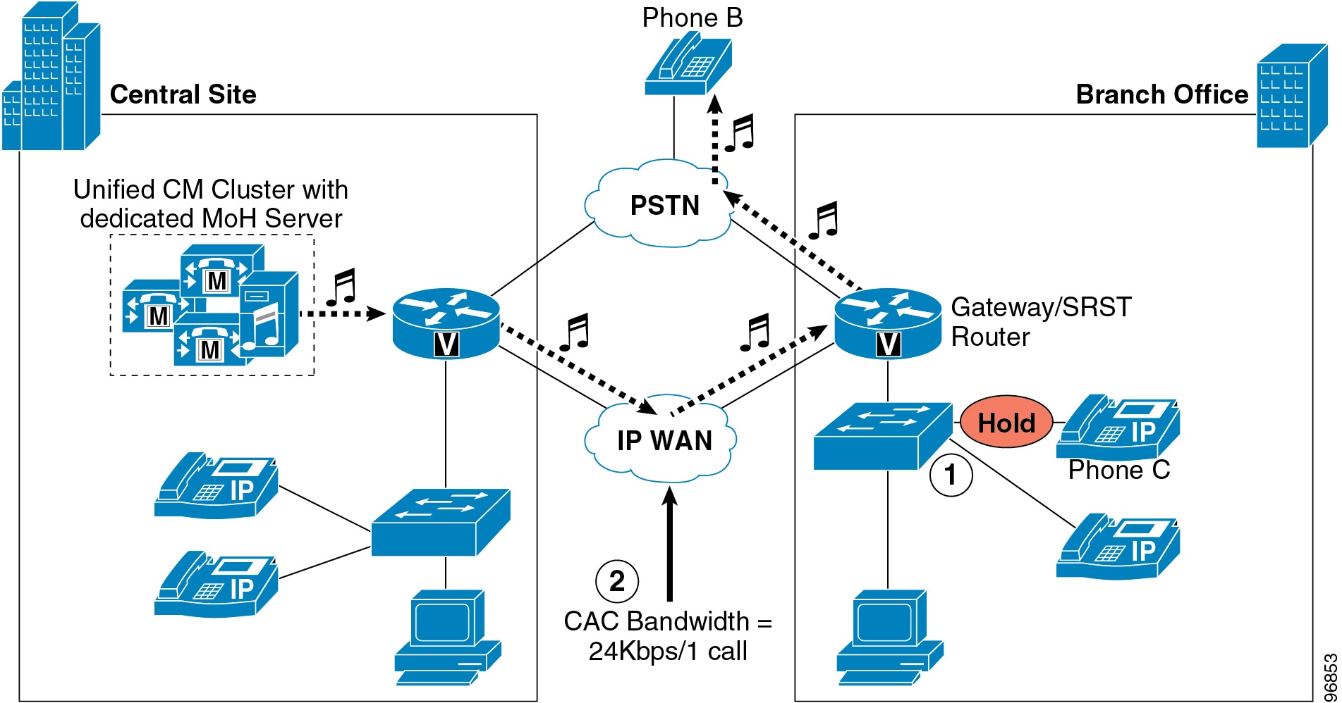
Figure 7-5 shows an example of call admission control and MoH in a centralized multisite deployment. For this example, assume that IP phone C is in a call with a PSTN phone (phone B). At this point, no bandwidth has been consumed on the WAN. When phone C pushes the Hold softkey (step 1), phone B receives an MoH stream from the central-site MoH server via the WAN, thereby consuming bandwidth on the link. Whether or not this bandwidth is taken into consideration by call admission control depends on the type of MoH stream. If multicast MoH is streamed, then call admission control will not consider the 24 kbps being consumed (therefore, QoS on the downstream WAN interfaces should be provisioned accordingly). However, if unicast MoH is streamed, call admission control will subtract 24 kbps from the available WAN bandwidth (step 2).
Note
Figure 7-5 Locations-Based Call Admission Control and MoH
Multicast MoH from Branch Routers
Beginning with Cisco Unified Survivable Remote Site Telephony (SRST) Release 3.0, MoH can be multicast in a remote or branch site via the branch SRST router's flash. Beginning with SRST Release 3.2, MoH can be multicast in a branch site via a live feed connected to an analog port on the branch SRST router. Multicast MoH from a branch router via these two methods enhances the Cisco Unified Communications MoH feature in both of the following scenarios:
•
When the WAN is up and the phones are controlled by Unified CM, this configuration can eliminate the need to forward MoH across the WAN to remote branch sites by providing locally sourced MoH.
•
When SRST is active and the branch devices have lost connectivity to the central-site Unified CM, the branch router can continue to provide multicast MoH.
When using the live feed option in either scenario, the SRST router provides redundancy by monitoring the live feed input, and it will revert to streaming MoH from a file in flash if the live feed is disconnected. You can use only a single multicast address and port number per SRST router to provide multicast MoH; therefore, the SRST router does not support streaming from both the live feed and the flash file at the same time. In addition, the SRST router can stream only a single audio file from flash.
Note
Non-Fallback Mode
During non-fallback mode (when the WAN is up and SRST is not active), the branch SRST router can provide multicast MoH to all local Cisco Unified Communications devices. To accomplish this, you must configure a Unified CM MoH server with an audio source that has the same multicast IP address and port number as configured on the branch router. In this scenario, because the multicast MoH audio stream is always coming from the SRST router, it is not necessary for the central-site MoH server audio source to traverse the WAN.
To prevent the central-site audio stream(s) from traversing the WAN, use one of the following methods:
•
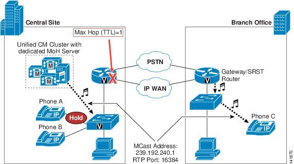
Configure the central-site MoH audio source with a maximum hop count (or TTL) low enough to ensure that it will not stream further than the central-site LAN.
•
Configure an ACL on the central-site WAN interface to disallow packets destined to the multicast group address(es) from being sent out the interface.
•
Do not configure multicast routing on the WAN interface, thus ensuring that multicast streams are not forwarded into the WAN.
Figure 7-6 illustrates streaming multicast MoH from a branch router when it is not in fallback mode. After phone A places phone C on hold, phone C receives multicast MoH from the local SRST router. In this example, the MoH server is streaming a multicast audio source to 239.192.240.1 (on RTP port 16384); however, this stream has been limited to a maximum hop of one (1) to ensure that it will not travel off the local MoH server's subnet and across the WAN. At the same time, the branch office SRST router/gateway is multicasting an audio stream from either flash or a live feed. This stream is also using 239.192.240.1 as its multicast address and 16384 as the RTP port number. When phone A presses the Hold softkey, phone C receives the MoH audio stream sourced by the SRST router.
Figure 7-6 Multicast MoH from Branch Router
When using this method for delivering multicast MoH, configure all devices within the Unified CM cluster to use the same user hold and network hold audio source and configure all branch routers with the same multicast group address and port number. Because the user or network hold audio source of the holder is used to determine the audio source, if you configure more than one user or network hold audio source within the cluster, there is no way to guarantee that a remote holdee will always receive the local MoH stream. For example, suppose a central-site phone is configured with an audio source that uses group address 239.192.254.1 as its user and network hold audio source. If this phone places a remote device on hold, the remote device will attempt to join 239.192.254.1 even if the local router flash MoH stream is sending to multicast group address 239.192.240.1. If instead all devices in the network are configured to use the user/network hold audio source with multicast group address 239.192.240.1 and all branch routers are configured to multicast from flash on 239.192.240.1, then every remote device will receive the MoH from its local router.
In networks with multiple branch routers configured to stream multicast MoH, this allows for more than 51 unique MoH audio sources within the Unified CM cluster. Each branch site router can multicast a unique audio stream, although all routers must multicast this audio on the same multicast group address. In addition, the central-site MoH server can multicast a MoH stream on this same multicast group address. Thus, if there are 100 branch sites each multicasting audio, then the cluster actually contains 101 unique MoH audio sources (100 branch streams and one central-site stream). If you want more than 51 unique audio streams in the central site, see the methods described in Using Multiple Fixed (Live) Audio Sources.
Fallback Mode
During fallback mode (when the WAN is down and SRST is active), the branch SRST router can stream multicast MoH to all analog and digital ports within the chassis, thereby providing MoH to analog phones and PSTN callers. Beginning with Cisco Unified SRST Release 4.0, SCCP IP phones in fallback mode can also receive the multicast MoH stream. At this time, SIP IP Phones will receive tone-on-hold.
The branch router's configuration for fallback mode multicast MoH is the same as the normal operation configuration. However, which multicast address you configure on the router depends on the intended operation. If you want the branch router to provide multicast MoH to devices only in fallback mode (for example, if MoH received by remote devices is to be sourced from the central-site MoH server during non-fallback mode), then the multicast address and port number configured on the SRST router should not overlap with any of the central-site MoH server audio sources. Otherwise, remote devices might continue to receive MoH from the local router flash, depending on the configured user/network hold audio sources.
Note that, once the branch SRST/gateway router is configured to provide multicast MoH, the router will continue to multicast the MoH stream even when not in fallback mode.
Beginning with Cisco Unified SRST Release 4.0, it is also possible to configure the fallback mode to use Cisco Unified Communications Manager Express (Unified CME) in SRST mode. Fallback mode behavior is still the same, but the configuration commands are slightly different. SRST commands are entered under the Cisco IOS call-manager-fallback construct, while the commands for Unified CME in SRST mode are entered under telephony-service.
There are four methods of providing multicast MoH via SRST:
•
•
•
•
For more details on configuration of Cisco SRST and Unified CME, refer to the Cisco Unified SRST System Administrator Guide and the Cisco Unified Communications Manager Express System Administrator Guide, both available at
Distributed Multisite Deployments
Multisite IP telephony deployments with distributed call processing typically contain WAN or MAN connections between the sites. These lower-speed links usually cause bandwidth and throughput bottlenecks. To minimize bandwidth consumption on these links, Cisco recommends use of the G.729 codec for all MoH audio streams traversing them. Because the G.729 codec is optimized for voice and not music applications, you should use G.729 only across the WAN/MAN links, where the bandwidth savings far outweighs the lower quality afforded by G.729 for MoH transport.
Unlike with centralized multisite deployments, in situations where G.711 might be required for MoH audio streams traveling across a WAN, MoH audio streams cannot be forced to G.711 in a distributed multisite deployment. Even when MoH servers are placed in a separate Unified CM region and the G.711 codec is configured between this region and the intercluster or SIP trunk's region, the codec of the original voice call is maintained when a call between the two clusters is placed on hold by either phone. Because these intercluster calls are typically encoded using G.729 for bandwidth savings, a MoH stream from either cluster will also be encoded using G.729.
Furthermore, multicast MoH is not supported for calls between Unified CM clusters (intercluster calls). Therefore, you must configure at least one unicast MoH resource in each Unified CM cluster if you want MoH on the intercluster or SIP trunk.
Proper multicast address management is another important design consideration in the distributed intercluster environment. All MoH audio source multicast addresses must be unique across all Unified CM clusters in the deployment to prevent possible overlap of streaming resources throughout the distributed network.
Clustering Over the WAN
As its name suggests, clustering-over-the-WAN deployments also contain the same type of lower-speed WAN links as other multisite deployments and therefore are subject to the same requirements for G.729 codec, multicast transport mechanism, and solid QoS for MoH traffic traversing these links.
In addition, you should deploy MoH server resources at each side of the WAN in this type of configuration. In the event of a WAN failure, devices on each side of the WAN will be able to continue to receive MoH audio streams from their locally deployed MoH server. Furthermore, proper MoH redundancy configuration is extremely important. The devices on each side of the WAN should point to an MRGL whose MRG has a priority list of MoH resources with at least one local resource as the highest priority. Additional MoH resources should be configured for this MRG in the event that the primary server becomes unavailable or is unable to process requests. At least one other MoH resource in the list should point to an MoH resource on the remote side of the WAN in the event that resources at the local side of the WAN are unavailable.
Detailed Unicast and Multicast MoH Call Flows
The following sections provide detailed illustrations and explanations of unicast and multicast MoH call flows for both SCCP and SIP endpoints.
SCCP Call Flows
This section describes the call flows for music on hold with Skinny Client Control Protocol (SCCP) endpoints.
SCCP Multicast Call Flow
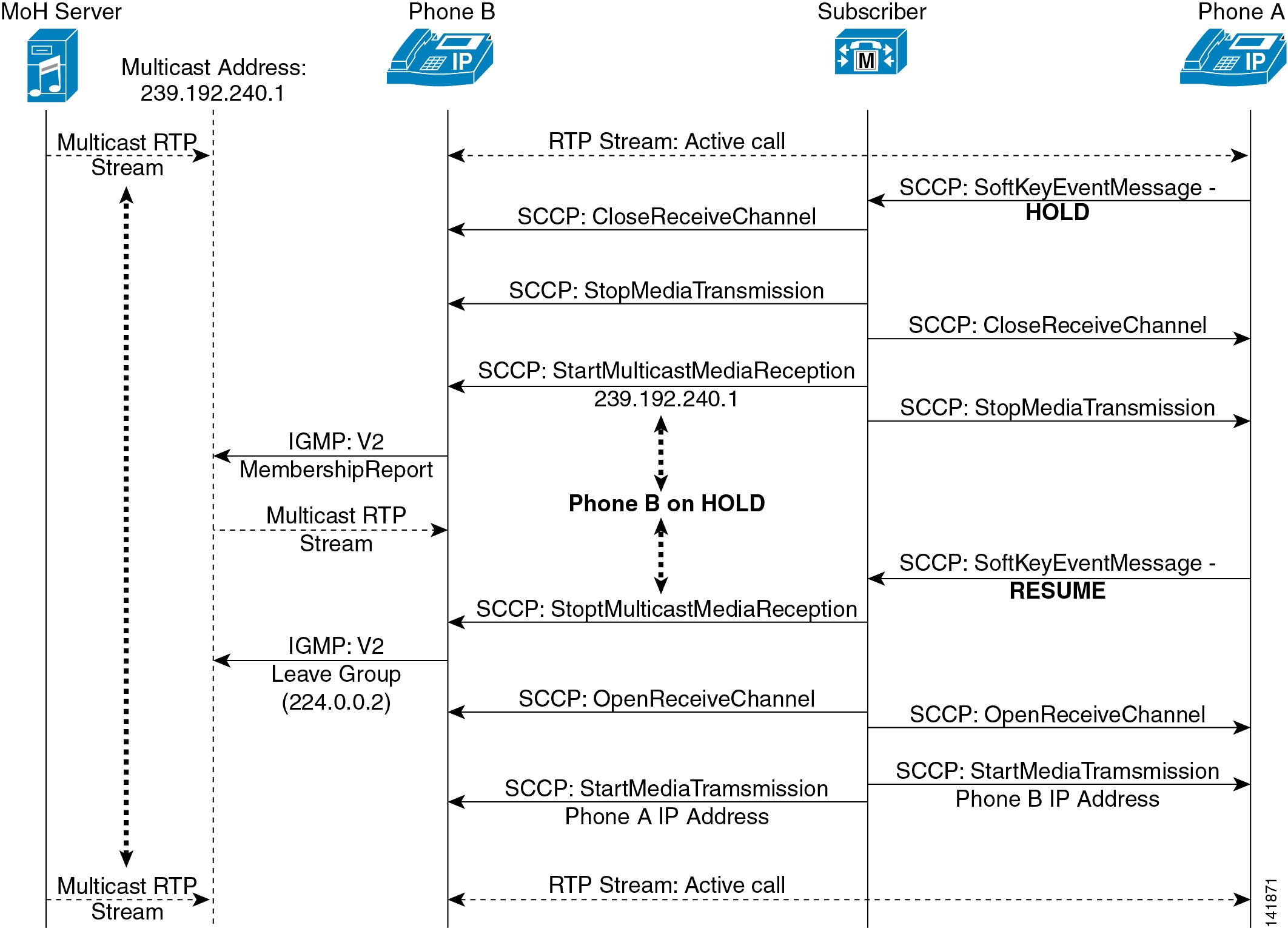
Figure 7-7 illustrates a typical SCCP multicast call flow. As shown in the diagram, when the Hold softkey is pressed at phone A, Unified CM instructs both phone A and phone B to Close Receive Channel and Stop Media Transmission. This action effectively stops the RTP two-way audio stream. Next, Unified CM tells phone B (the holdee) to Start Multicast Media Reception from multicast group address 239.192.240.1. The phone then issues an Internet Group Management Protocol (IGMP) V2 Membership Report message indicating that it is joining this group.
Figure 7-7 Detailed SCCP Multicast MoH Call Flow
Meanwhile, the MoH server has been sourcing RTP audio to this multicast group address and, upon joining the multicast group, phone B begins receiving the MoH stream. Once phone A presses the Resume softkey, Unified CM instructs phone B to Stop Multicast Media Reception. Phone B then sends an IGMP V2 Leave Group message to 224.0.0.2 to indicate that the multicast stream is no longer needed. This effectively ends the MoH session. Next, Unified CM sends a series of Open Receive Channel messages to phones A and B, just as would be sent at the beginning of a phone call between the two phones. Soon afterwards, Unified CM instructs both phones to Start Media Transmission to each other's IP addresses. The phones are once again connected via an RTP two-way audio stream.
Note
SCCP Unicast Call Flow
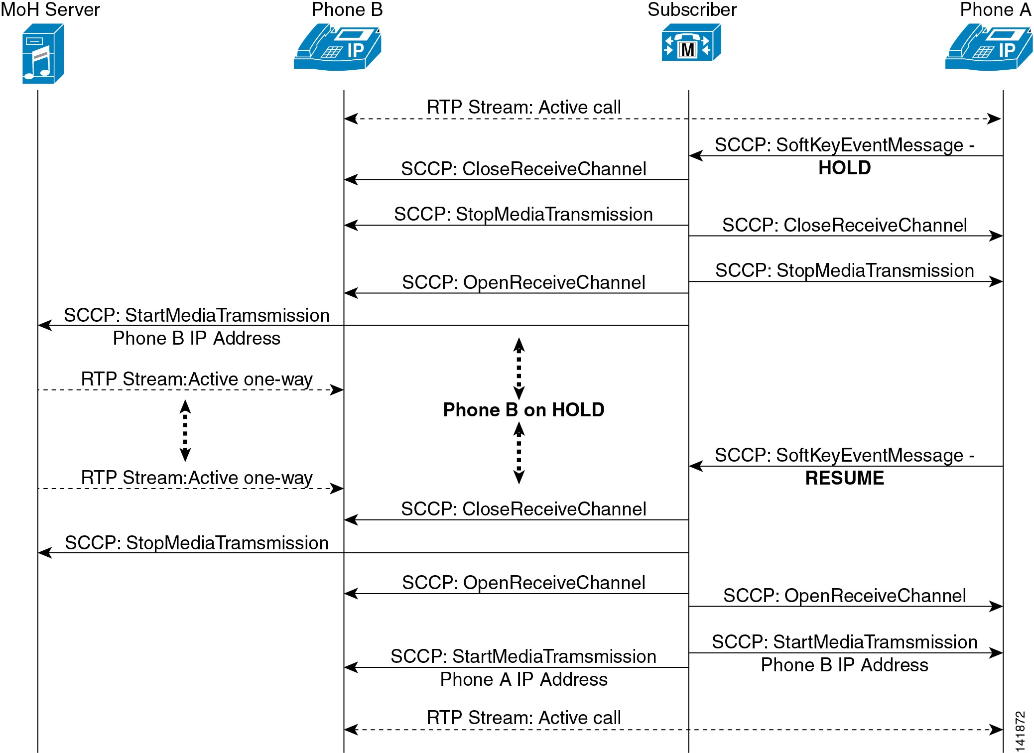
Figure 7-8 depicts an SCCP unicast MoH call flow. In this call flow diagram, when the Hold softkey is pressed at phone A, Unified CM instructs both phone A and phone B to Close Receive Channel and Stop Media Transmission. This action effectively stops the RTP two-way audio stream. Up to this point, unicast and multicast MoH call flows behave exactly the same.
Figure 7-8 Detailed SCCP Unicast MoH Call Flow
Next, Unified CM tells phone B (the holdee) to Open Receive Channel. (This is quite different from the multicast case, where Unified CM tells the holdee to Start Multicast Media Reception.) Then Unified CM tells the MoH server to Start Media Transmission to the IP address of phone B. (This too is quite different behavior from the multicast MoH call flow, where the phone is prompted to join a multicast group address.) At this point, the MoH server is sending a one-way unicast RTP music stream to phone B. When phone A presses the Resume softkey, Unified CM instructs the MoH server to Stop Media Transmission and instructs phone B to Close Receive Channel, effectively ending the MoH session. As with the multicast scenario, Unified CM sends a series of Open Receive Channel messages and Start Media Transmissions messages to phones A and B with each other's IP addresses. The phones are once again connected via an RTP two-way audio stream.
SIP Call Flows
This section describes the call flows for music on hold with Session Initiation Protocol (SIP) endpoints.
SIP Multicast Call Flow
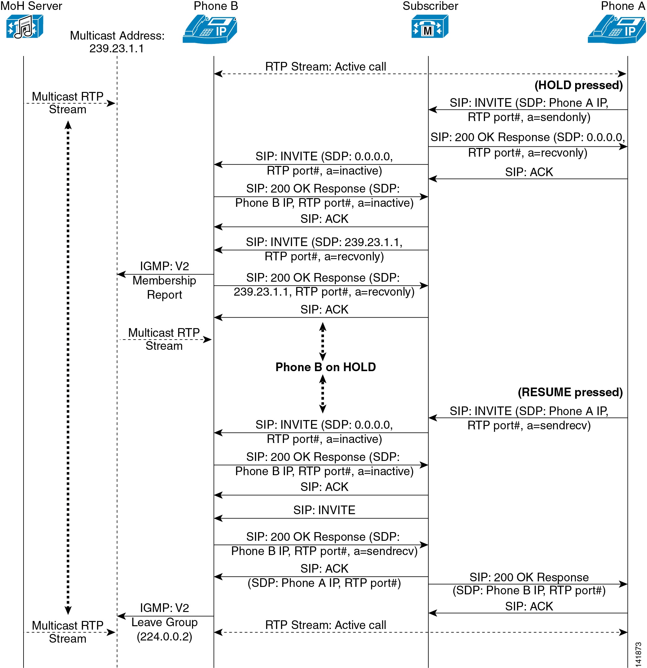
Figure 7-9 illustrates a typical SIP multicast call flow. As shown in the diagram, when the Hold softkey is pressed at phone A, phone A sends a SIP INVITE with a Session Description Protocol (SDP) connection information indication of phone A's IP address and a media attribute indication of sendonly. Unified CM then instructs phone A to disconnect the RTP stream via a SIP 200 OK Response with an SDP connection information indication of 0.0.0.0 and a media attribute indication of recvonly. Phone B is then told to disconnect the RTP stream via a SIP INVITE from Unified CM with an SDP connection information indication of 0.0.0.0 and a media attribute of inactive. After a SIP 200 OK Response is sent back from phone B to Unified CM indicating an SDP media attribute of inactive, Unified CM then sends a SIP INVITE to phone B with an SDP connection information indication of the MoH multicast group address (in this case 239.23.1.1) and a media attribute of recvonly.
Figure 7-9 Detailed SIP Multicast MoH Call Flow
Next, phone B in Figure 7-9 issues an IGMP V2 Membership Report message indicating that it is joining this multicast group. In addition, phone B sends a SIP 200 OK Response back to Unified CM indicating an SDP media attribute of recvonly in response to the previous SIP INVITE. Meanwhile, the MoH server has been sourcing RTP audio to this MoH multicast group address and, upon joining the multicast group, phone B begins receiving the one-way MoH stream.
When the user at phone A presses the Resume softkey, phone A sends a SIP INVITE with an SDP connection information indication of phone A's IP address and media attribute indications of phone A's receiving RTP port and sendrecv. Unified CM then instructs phone B to disconnect from the multicast MoH stream via a SIP INVITE with an SDP connection information indication of 0.0.0.0 and a media attribute indication of inactive. A SIP 200 OK Response is sent back from phone B to Unified CM, indicating an SDP media attribute of inactive.
Next Unified CM sends a SIP INVITE to phone B, and phone B responds with a SIP 200 OK Response with an SDP connection information indication of phone B's IP address and media attribute indications of phone B's receiving RTP port and sendrecv. Unified CM responds by sending a SIP ACK to phone B with an SDP connection information indication of phone A's IP address and a media attribute of phone A's receiving RTP port number. Likewise, Unified CM forwards a SIP 200 OK Response to phone A's original resuming SIP INVITE, with an SDP connection information indication of phone B's IP address and a media attribute of phone B's receiving RTP port number. Phone B then sends an IGMP V2 Leave Group message to 224.0.0.2 to indicate that the multicast stream is no longer needed. Finally, the RTP two-way audio stream between phone A and B is reestablished.
Note
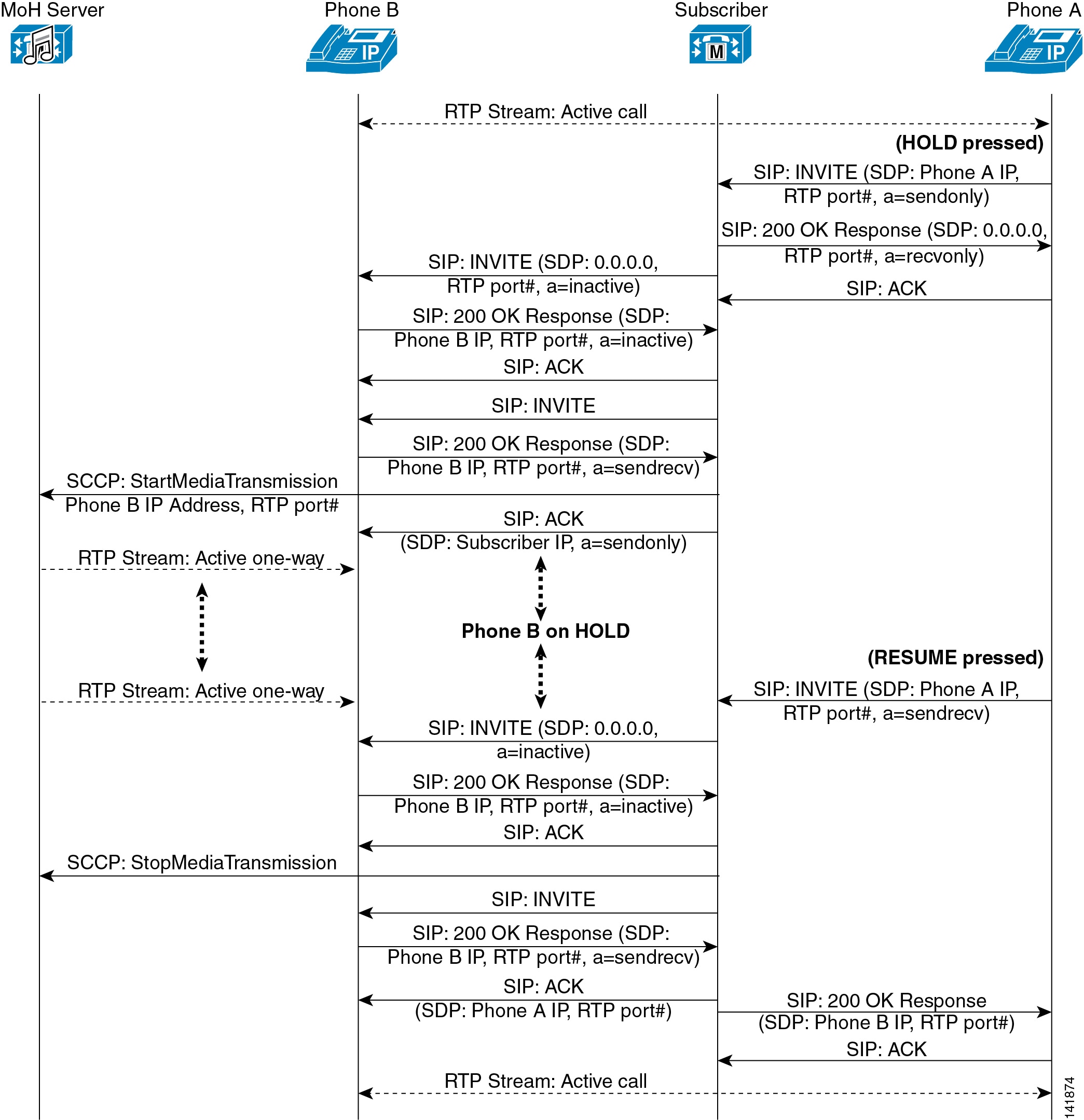
SIP Unicast Call Flow
Figure 7-10 depicts a SIP unicast MoH call flow. As shown in the diagram, when the Hold softkey is pressed at phone A, phone A sends a SIP INVITE with an SDP connection information indication of phone A's IP address and a media attribute indication of sendonly. Unified CM then instructs phone A to disconnect the RTP stream via a SIP 200 OK Response with an SDP connection information indication of 0.0.0.0 and a media attribute indication of recvonly. Phone B is then told to disconnect the RTP stream via a SIP INVITE from Unified CM, with an SDP connection information indication of 0.0.0.0 and a media attribute of inactive. Next a SIP 200 OK Response is sent back from phone B to Unified CM, indicating an SDP media attribute of inactive. Up to this point, unicast and multicast MoH call flows are exactly the same.
Figure 7-10 Detailed SIP Unicast MoH Call Flow
Unified CM then sends a SIP INVITE to phone B, and Phone B responds back with a SIP 200 OK Response indicating an SDP connection information indication with phone B's IP address and media attribute indications of phone B's receiving RTP port number and sendrecv. Unified CM then sends a SCCP StartMediaTransmission message to the MoH server, with phone B's address and receiving RTP port number. This is followed by a SIP ACK from Unified CM to phone B indicating SDP connection information of the Unified CM IP address and a media attribute of sendonly. Meanwhile, the MoH server begins sourcing RTP audio to phone B, and phone B begins receiving the one-way MoH stream.
When the user at phone A presses the Resume softkey, phone A sends a SIP INVITE with an SDP connection information indication of phone A's IP address and media attribute indications of phone A's receiving RTP port and sendrecv. Unified CM then instructs phone B to disconnect from the multicast MoH stream via a SIP INVITE with an SDP connection information indication of 0.0.0.0 and a media attribute indication of inactive. A SIP 200 OK Response is sent back from phone B to Unified CM, indicating an SDP media attribute of inactive. Then Unified CM sends a SCCP StopMediaTransmission message to the MoH server, causing the MoH server to stop forwarding the MoH stream to phone B.
Next Unified CM sends a SIP INVITE to phone B, and phone B responds with a SIP 200 OK Response with an SDP connection information indication of phone B's IP address and media attribute indications of phone B's receiving RTP port and sendrecv. Unified CM responds by sending a SIP ACK to phone B, with an SDP connection information indication of phone A's IP address and a media attribute of phone A's receiving RTP port number. Likewise, Unified CM forwards a SIP 200 OK Response to phone A's original resuming SIP INVITE with an SDP connection information indication of phone B's IP address and a media attribute of phone B's receiving RTP port. Finally, the RTP two-way audio stream between phone A and B is reestablished.
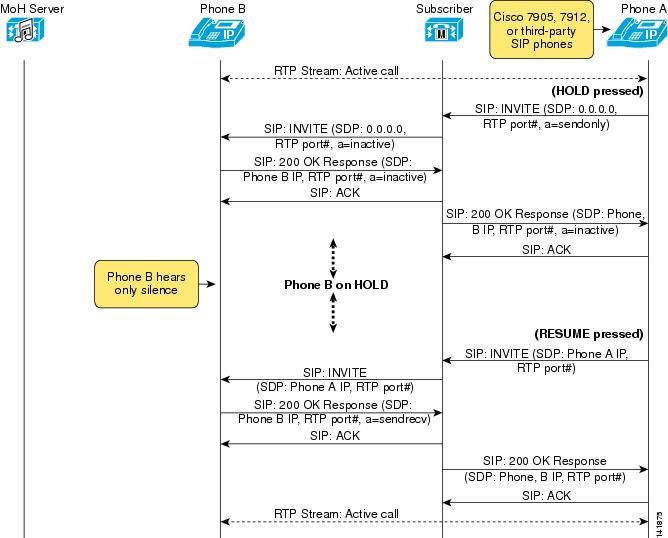
SIP Media Hold Call Flow
Figure 7-11 depicts an RFC 2543 media hold call flow. This call flow occurs only when the phone placing the call on hold (in this case phone A) is a Cisco Unified IP Phone 7905 or 7912, or any third-party SIP phone. As shown in the diagram, when the Hold softkey is pressed at phone A, phone A sends a SIP INVITE with an SDP connection information indication of 0.0.0.0 and a media attribute indication of sendonly. Phone B is then told to disconnect the RTP stream via a SIP INVITE from Unified CM, with an SDP connection information indication of 0.0.0.0 and a media attribute of inactive. Next a SIP 200 OK Response is sent back from phone B to Unified CM, with an SDP connection information indication of phone B's IP address and media attribute indications of phone B's receiving RTP port number and inactive. Next Unified CM forwards a SIP 200 OK Response back to phone A in response to phone A's original holding SIP INVITE, with an SDP connection information indication of phone B's IP address and media attribute indications of phone B's receiving RTP port and inactive.
At this point, phone B is on hold but receiving no MoH, so the phone B user hears only silence.
Figure 7-11 Detailed SIP Media Hold Call Flow
When the user at phone A presses the Resume softkey, phone A sends a SIP INVITE with an SDP connection information indication of phone A's IP address and a media attribute indication of phone A's receiving RTP port. Unified CM then sends a SIP INVITE to phone B, with an SDP connection information indication of phone A's IP address and a media attribute indication of phone A's receiving RTP port. Phone B in turn responds with a SIP 200 OK Response with an SDP connection information indication of phone B's IP address and media attribute indications of phone B's receiving RTP port and sendrecv. Likewise, Unified CM forwards a SIP 200 OK Response to phone A's original resuming SIP INVITE, with an SDP connection information indication of phone B's IP address and a media attribute indication of phone B's receiving RTP port. Finally, the RTP two-way audio stream between phone A and B is reestablished.
Note