-
Cisco Unified Communications SRND Based on Cisco Unified Communications Manager 5.x
-
Preface
-
Introduction
-
IP Telephony Deployment Models
-
Network Infrastructure
-
Gateways
-
Cisco Unified Communications Manager Trunks
-
Media Resources
-
Music on Hold
-
Call Processing
-
Call Admission Control
-
Dial Plan
-
Emergency Services
-
Third-Party Voicemail Design
-
Cisco Unity
-
Cisco Unified MeetingPlace Integration
-
Cisco Unified MeetingPlace Express
-
IP Video Telephony
-
LDAP Directory Integration
-
IP Telephony Migration Options
-
Voice Security
-
IP Telephony Endpoints
-
Cisco Unified Presence
-
Cisco Unified Communications Manager Applications
-
Cisco Mobility Applications
-
Recommended Hardware and Software Combinations
-
Glossary
-
Index
-
Table Of Contents
IP Phone Services Phone Support
Unified CM Services and IP Phone Service Enterprise Service Parameters
Unified CM Services for IP Phone Services
IP Phone Service Enterprise Service Parameters
IP Phone Services Architecture
Guidelines and Restrictions for IP Phone Services
Unified CM Services and EM Service Parameters
Guidelines and Restrictions for EM
EM Interactions: Unified CM Assistant, AC, and WebDialer
Unified CM Assistant Phone Support
Unified CM Services and Unified CM Assistant Service Parameters
Unified CM Services for Unified CM Assistant
Unified CM Assistant Service Parameters
Unified CM Assistant Functionality and Architecture
Unified CM Assistant Proxy Line Mode
Unified CM Assistant Share Lined Mode
Unified CM Assistant Architecture
Unified CM Assistant Dial Plan Considerations
Unified CM Assistant Console Installation
Unified CM Assistant Desktop Console QoS
Unified CM Assistant Console Directory Window
Unified CM Assistant Phone Console QoS
Unified CM Assistant Redundancy
Service and Component Redundancy
Device and Reachability Redundancy
Guidelines and Restrictions for Unified CM Assistant
Unified CM Assistant Performance and Capacity
Unified CM Assistant Interactions with EM
Unified CM Services and AC Service Parameters
AC and AC Device Authentication Application Users
AC Functionality and Architecture
Attendant Console Desktop Application
Attendant Console Installation
Attendant Console Directory Window
Service and Component Redundancy
Device and Reachability Redundancy
Guidelines and Restrictions for AC
Unified CM Services and WebDialer Service Parameters
Unified CM Services for WebDialer
WebDialer Functionality and Architecture
Service and Component Redundancy
Device and Reachability Redundancy
Guidelines and Restrictions for WebDialer
WebDialer Performance and Scalability
WebDialer Interactions with EM
Cisco Unified CM Applications
Cisco Unified Communications Manager (Unified CM) applications provide numerous operational and functional enhancements to basic IP telephony. External eXtensible Markup Language (XML) productivity applications or IP Phone Services can be run on the web server and/or client on most Cisco Unified IP Phones. For example, the IP phone on a user's desk can be used to get stock quotes, weather information, flight information, and other types of web-based information. In addition, custom IP phone service applications can be written that allow users to track inventory, bill customers for time, or control conference room environments (lights, video screen, temperature, and so forth). Unified CM also has a number of integrated applications that provide additional functionality, including:
•
Cisco Extension Mobility (EM)
The Extension Mobility feature enables mobile users to configure a Cisco Unified IP Phone as their own, on a temporary basis, by logging in to that phone.
•
Unified CM Assistant is a Unified CM integrated application that enables assistants to handle one or more managers' incoming phone calls.
•
The Attendant Console enables one or more receptionists to answer and transfer (or dispatch) calls within an organization.
•
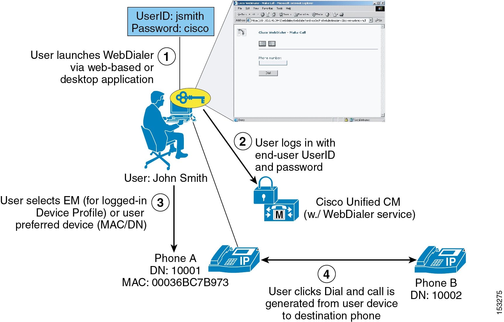
WebDialer is a click-to-dial application for Unified CM that enables users to place calls easily from their PCs using any supported phone device.
In some cases these integrated applications also invoke IP Phone Services to provide additional functionality.
This chapter examines the following Unified CM applications:
IP Phone Services
Cisco Unified IP Phone Services are applications that utilize the web client and/or server and XML capabilities of the Cisco Unified IP Phone. The Cisco Unified IP Phone firmware contains a micro-browser that enables limited web browsing capability. These phone service applications provide the potential for value-added services and productivity enhancement by running directly on the user's desktop phone. For purposes of this chapter, the term phone service refers to an application that transmits and receives content to and from the Cisco Unified IP Phone.
IP Phone Services Phone Support
The following phones support IP Phone Services:
•
•
•
•
IP Phone Services can also run on the following IP phones, however these phone models support only text-based XML applications:
•
•
•
•
•
All of the IP Phones listed above can process a limited set of Cisco-defined XML objects for enabling the user interface (UI) between the phone and the web server that contains the running phone service.
Note that the phones listed above support IP Phone Services for both the Skinny Client Control Protocol (SCCP) and Session Initiation Protocol (SIP). Beginning with Cisco Unified Communications Manager release 5.1.1(b), the Cisco Unified IP Phones 7942G, 7945G, 7962G, 7965G, and 7975G also support IP Phone Services with both SCCP and SIP loads.
Unified CM Services and IP Phone Service Enterprise Service Parameters
To enable IP Phone Services, the system administrator must ensure that the Cisco Unified IP Phone Service network service is enabled under the Unified CM Serviceability interface. In addition, the administrator can use service parameters within Unified CM to customize and configure certain aspects of Unified CM and application behavior. There are a number of enterprise service parameters that provide configuration and customization options for IP Phone Services, as described in the following sections.
Unified CM Services for IP Phone Services
IP Phone Services rely on the Cisco CallManager Cisco IP Phone Services network service on Unified CM in order to function. This feature is installed and activated by default when Unified CM is installed on a server.
IP Phone Service Enterprise Service Parameters
There are a number of pertinent Enterprise Service Parameters that relate to IP Phone Services. The following items represent a partial list of configuration parameters under the Phone URL Parameters section of the Unified CM Enterprise Service Parameters configuration page that relate to IP Phone Services and XML operation of IP Phones:
•
This URL points to the authenticate.jsp service on Unified CM, which provides an authentication proxy service between Cisco Unified IP Phones and Unified CM. The URL is used to validate "push" requests made directly to the phone by the phone services. It is automatically configured at installation time. If no value is specified for this parameter, phone services will not be able to push content to the phone.
•
This URL points to the xmldirectory.jsp service on Unified CM, which generates and returns the directory menu presented when the user pushes the Directories (or book icon) button on the phone. The URL is automatically configured at installation time. If no value is specified for this parameter, the directory menu will not be available when the user pushes the Directories button.
•
This URL, if specified, points to a service that provides text or images to be displayed on the phone screen when the phone is idle. This parameter is closely coupled with the URL Idle Time parameter, which indicates how long the phone must be idle before initiating the service. By default this parameter is left blank (not configured) at installation time.
•
This parameter setting indicates the time in seconds that a phone will wait before initiating the URL Idle service. By default the parameter is set to 0 (zero) at installation time, indicating that the phone will never become idle.
•
This URL points to the GetTelecasterHelpText.jsp service on Unified CM, which generates and returns on-screen phone help for the phone keys and call statistics when the user presses the Help ("i" or "?") button (located to the right of the keypad). The URL is automatically configured at installation time. If no value is specified for this parameter, no help information will be displayed when the user pushes the Help button.
•
This URL points to the getservicesmenu.jsp service on Unified CM, which provides a list of user-subscribed phone services for the phone when the user presses the Services (or globe icon) button. It is automatically configured at installation time. If no value is specified for this parameter, a list of subscribed services will not be provided when the user pushes the Services button.
IP Phone Services Architecture
An IP Phone service can be initiated in several ways:
•
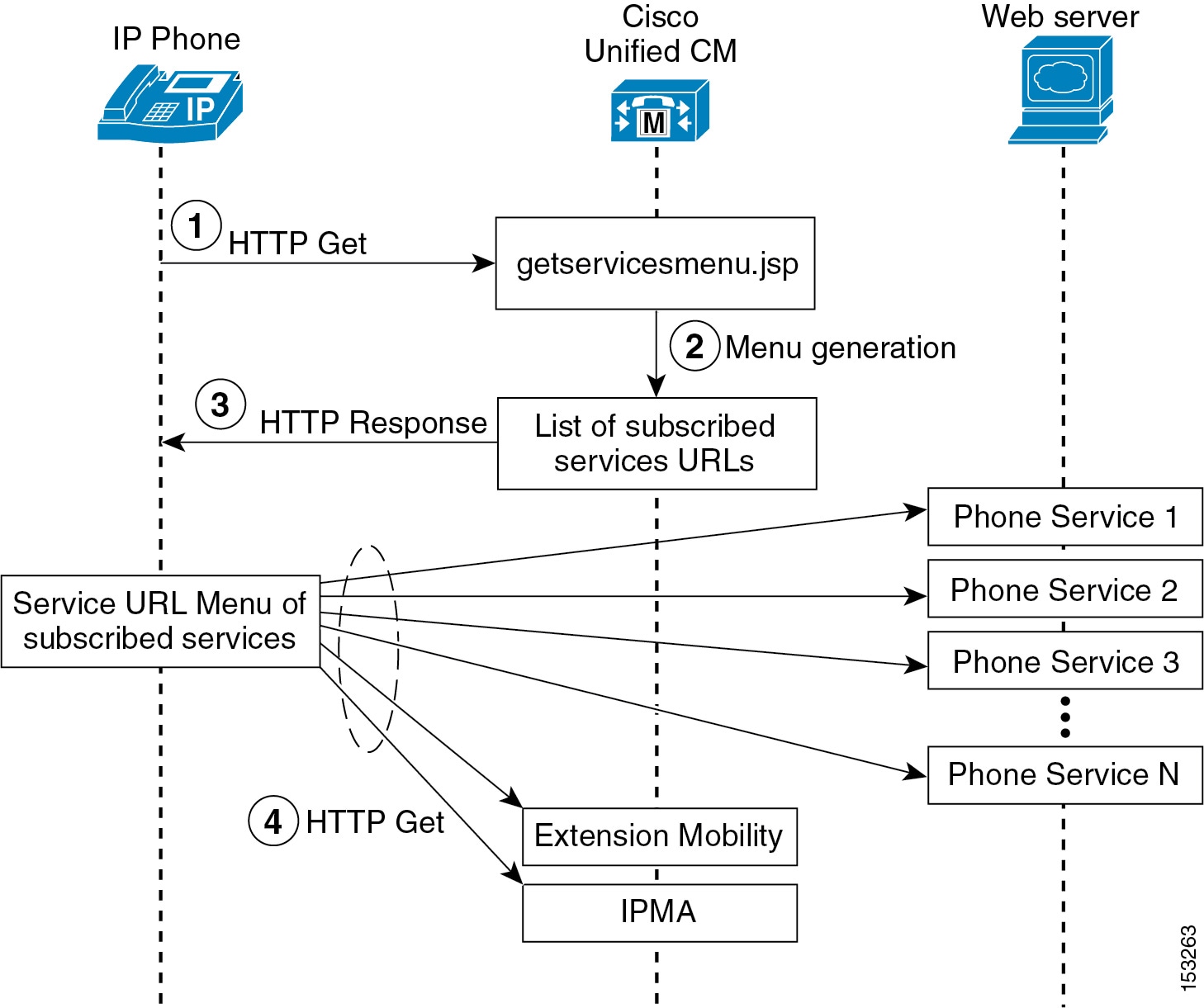
An IP Phone user presses the Services button, which sends an HTTP GET message to Unified CM for displaying a list of user-subscribed phone services. Figure 22-1 illustrates this functionality.
•
An idle time value can be set within the IP Phone firmware, as indicated by the URL Idle Time parameter. When this timeout value is exceeded, the IP Phone firmware itself initiates an HTTP GET to the idle URL location specified by the URL Idle parameter.
•
A phone service application can push content to the IP Phone by sending an HTTP POST message to the phone.
Note
Figure 22-1 shows a detailed illustration of the user-initiated IP Phone service operation. When a user presses the Services button, an HTTP GET message is sent from the IP Phone to the Unified CM getservicesmenu.jsp script by default (step 1). You can specify a different script by changing the URL Services parameter (see IP Phone Service Enterprise Service Parameters). The getservicesmenu.jsp script returns the list of phone service URL locations to which the individual user has subscribed (step 2). The HTTP response returns this list to the IP Phone (step 3). Any further phone service menu options chosen by the user continues the HTTP messaging between the user and the web server containing the selected phone service application (step 4).
Figure 22-1 User-Initiated IP Phone Service Architecture
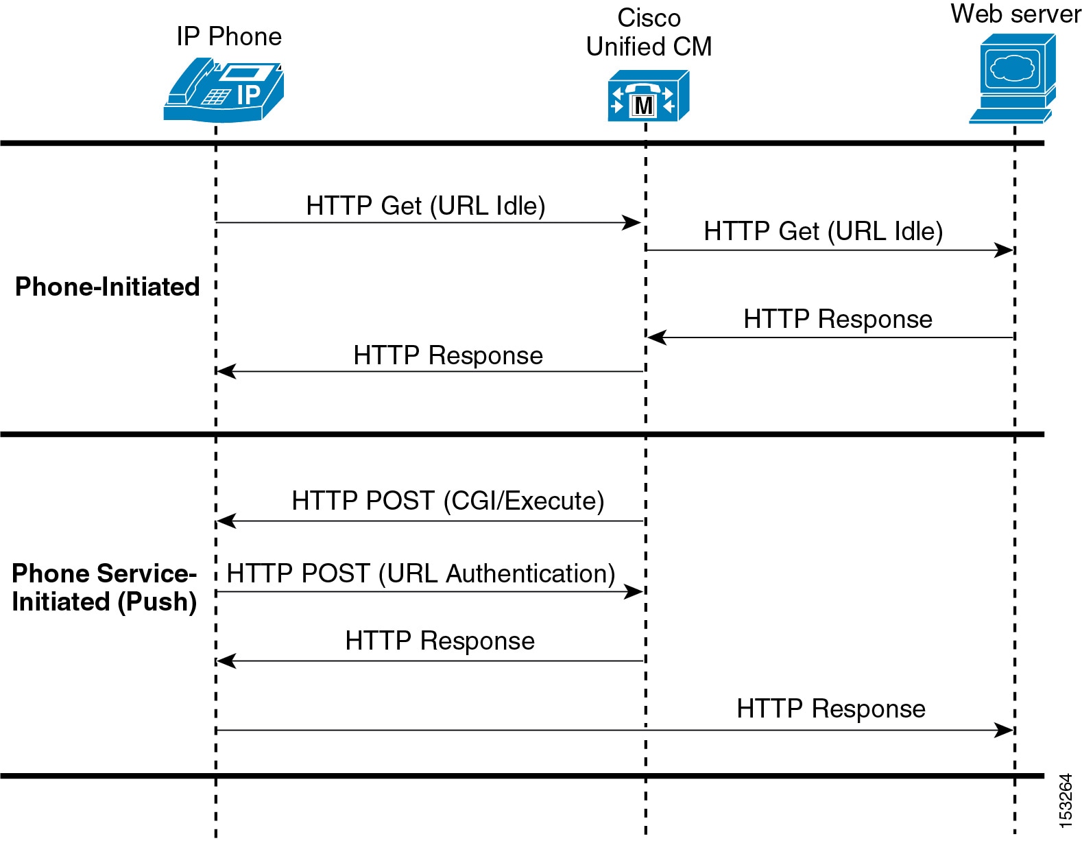
Figure 22-2 shows examples of both phone-initiated and phone service-initiated push functionality. In the phone-initiated example, the phone automatically sends an HTTP GET to the location specified under the URL Idle parameter (see IP Phone Service Enterprise Service Parameters) when the URL Idle Time is reached. The HTTP GET is forwarded via Unified CM to the external web server. The web server sends back an HTTP Response, which is relayed by Unified CM back to the phone, and the phone displays the text and/or image on the screen.
In the phone service-initiated push example, the phone service on the external web server sends an HTTP POST with a Common Gateway Interface (CGI) or Execute call to the phone's web server. Before performing the CGI or Execute call, the phone authenticates the request using the proxy authentication service specified by the URL Authentication parameter (see IP Phone Service Enterprise Service Parameters). This proxy authentication service provides an interface between the phone and the Unified CM directory in order to validate requests made directly to the phone. If the request is authenticated, Unified CM forwards an HTTP Response to the phone. The phone's web server then performs the requested action, and the phone returns an HTTP response back to the external web server. If authentication fails, Unified CM forwards a negative HTTP Response, and the phone does not perform the requested CGI or Execute action but in turn forwards a negative HTTP Response to the external web server.
Figure 22-2 Phone-Initiated and Phone Service-Initiated IP Phone Service Architecture
IP Phone Services Redundancy
To ensure reliable services for phone users, you must maintain a high level of system availability, with a seamless transition to redundant systems during a system failure. While most of the back-end processing of a phone service occurs on a web server, the phones still depend upon Unified CM to redirect them to the phone service. And in the case of Extension Mobility and Unified CM Assistant phone services, the service actually runs on the Unified CM server(s).
Given the architecture of IP phone service functionality and the message flows shown in Figure 22-1 and Figure 22-2, there are two main failure scenarios to be considered:
Failure Scenario 1: Server with Unified CM Cisco Unified IP Phone Services Fails
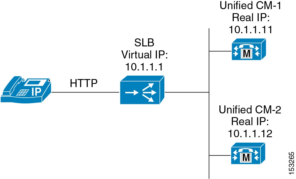
Redundancy in this case depends upon some type of server load balancing (SLB), as illustrated in Figure 22-3 where a virtual IP address is used to point to one or more Unified CM servers. This virtual IP address is used when configuring the URL Services parameter. Thus a Unified CM server failure does not prevent the IP Phone Services subscription list from being returned to the phone when the phone's Services button is pushed. In addition, phone services such as Extension Mobility and Unified CM Assistant that run on a Unified CM server are also potentially made redundant via this method.
Figure 22-3 Method for Providing Redundancy for Phone Services
Failure Scenario 2: External Web Server Hosting a Particular IP Phone Service Fails
In this scenario, the connection to the Unified CM server is preserved, but the link fails to the web server hosting the user-subscribed phone service. This is an easier scenario to provision for redundancy because the IP Phone is still able to access the Unified CM server when the Services button is pressed. In this case, the IP Phone is similar to any other HTTP client accessing a web server. As a result, you can again use some type of SLB functionality (similar to the one indicated in Figure 22-3) to redirect the HTTP request from the phone to one or more redundant web servers hosting the user-subscribe phone service.
IP Phone Services Scalability
Cisco Unified IP Phone Services act, for the most part, as an HTTP client. In most cases it uses Unified CM only as a redirect server to the location of the subscribed service. Because Unified CM acts as a redirect server to the phone service, there is minimal performance impact on Unified CM when a user initiates a phone service request by pressing the Services key.
Note
Because the IP Phone is either an HTTP client or server, estimating the required bandwidth used by an IP Phone service is similar to estimating the bandwidth of an HTTP browser accessing the same text as HTTP content residing on a web hosting server.
Guidelines and Restrictions for IP Phone Services
With the exception of the integrated Extension Mobility and Unified CM Assistant application's Phone Services, IP Phone services must reside on a separate web server. Running phone services other than Extension Mobility and IP Manager Application on the Unified CM server is not supported.
Extension Mobility (EM)
The Cisco Extension Mobility (EM) feature enables users to configure a Cisco Unified IP Phone as their own, on a temporary basis, by logging in to that phone. After a user logs in, the phone adopts the user's individual device profile information, including line numbers, speed dials, services links, and other user-specific properties of a phone. For example, when user X occupies a desk and logs in to the phone, that user's directory number(s), speed dials, and other properties appear on that phone; but when user Y uses the same desk at a different time, user Y's information appears. The EM feature dynamically configures a phone according to the authenticated user's device profile. The benefit of this application is that it allows users to be reached at their own extension on any phone within the Unified CM cluster, regardless of physical location, provided the phone supports EM.
EM Phone Support
The following Skinny Client Control Protocol (SCCP) phones support EM:
•
•
•
•
•
•
•
•
•
The following Session Initiation Protocol (SIP) phones support EM:
•
•
•
•
•
Note
Beginning with Cisco Unified Communications Manager release 5.1.1(b), the Cisco Unified IP Phones 7942G, 7945G, 7962G, 7965G, and 7975G also support EM.
Unified CM Services and EM Service Parameters
To enable the EM application, the system administrator must activate and start a number of Unified CM services from the Unified CM Serviceability interface. In addition, EM service parameters provide configuration and customization options for determining how the EM application behaves.
Unified CM Services for EM
The EM application relies on the Cisco Extension Mobility feature service, which you must activate manually from the Serviceability page.
EM also relies on the following network services, which are activated automatically on Unified CM during installation:
•
•
The Cisco Extension Mobility Application service provides an interface between the EM user phone and the Cisco Extension Mobility service. In addition, the Cisco Extension Mobility Application service subscribes to the change notification indications within the cluster and maintains a list of nodes in the cluster that have an active Cisco Extension Mobility service. By subscribing to change notification within the cluster, the Cisco Tomcat network service and the Cisco Extension Mobility feature service do not have to be restarted after changes are made to the EM service parameters.
The Unified CM Cisco Unified IP Phone Services service is needed to provide access to the EM phone service. The URL used to define the EM phone service is:
http://<Publisher_IP-Address>/emapp/EMAppServlet?device=#DEVICENAME#
For example:
http://10.1.1.1/emapp/EMAppServlet?device=#DEVICENAME#
EM Service Parameters
The following items represent a partial list of Cisco EM Service Parameters related to Extension Mobility functionality:
•
This parameter indicates whether EM users will be logged out automatically when the Maximum Login Time is reached. By default the value is set to False, meaning EM users are not automatically logged out.
•
This parameter indicates the number of hours and/or minutes (hh:mm) an EM user can stay logged in before being logged out automatically. Automatic logout at the time specified occurs only if the Enforce Maximum Login Time parameter is set to True.
•
This parameter indicates whether an EM user is allowed to log in to more than one device at one time. By default multiple logins by a single user are not allowed, and attempts by a user to log in to another device while logged on to one device results in the following message:
Login Unsuccessful
[25]User logged in elsewhere.•
This parameter indicates whether the last userID used to log in to a device will be remembered during subsequent attempts to log in to that same device. If this value is set to True, the last logged-in userID information is stored in a table in the Unified CM database for efficient retrieval. Upon a subsequent login attempt, the UserID field in the login screen on phone is pre-populated with the stored userID value.
•
This parameter indicates whether the call logs specified for the Directories button menu are cleared at EM login and logout. This parameter affects the following logs: Missed Calls, Received Calls, and Placed Calls. If the value is set to True, then these logs are cleared during login and manual logout.
One exception is that these logs are not cleared when the user is logged out automatically. Therefore, logs are not cleared when the Maximum Login Time is reached (assuming Enforce Maximum Login Time is set to True) and the user is automatically logged out of the phone. Likewise, if a Unified CM Administrator clicks on the Log Out button under the Extension section of the phone/device configuration screen, the logs are not cleared.
For a complete list of Extension Mobility service parameters, consult the Cisco Extension Mobility chapter of the Cisco Unified Communications Manager Features and Services Guide, available at
http://www.cisco.com/en/US/products/sw/voicesw/ps556/prod_maintenance_guides_list.html
EM Architecture
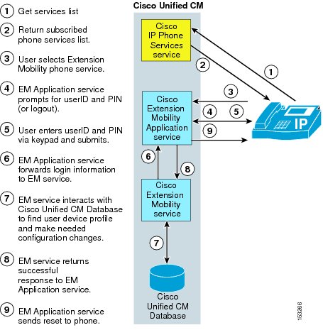
Figure 22-4 depicts the message flows and architecture of the EM application. When a phone user wants to access the EM application, the following sequence of events occurs:
1.
2.
Note
3.
4.
5.
6.
7.
8.
9.
Figure 22-4 EM Application Architecture and Message Flow
EM Redundancy
According to the EM architecture illustrated in Figure 22-4, reads and writes to the Unified CM database are required. Based on current Unified CM cluster architecture, the publisher server is the only node capable of writing to the Unified CM database. Therefore, EM functionality is dependent upon the publisher server. If the publisher is unavailable, then EM logins and logouts are not possible. Because there is no mechanism for publisher redundancy, the publisher is a single point of failure when it comes to EM operation. For this reason, Cisco recommends that the three required services for EM (IP Phone Services, Extension Mobility, and Extension Mobility Application services) all run on the publisher. Running these services on other nodes in the cluster is pointless because they will provide no functionality if the publisher is unavailable.
Note
As mentioned previously, because the Extension Mobility Application service subscribes to cluster change notification, it maintains a list of all nodes in the cluster with the Extension Mobility service activated. Therefore, the Extension Mobility service could be run on multiple servers within the cluster, and the Extension Mobility Application service could provide automatic failover to other nodes running the Extension Mobility service. However, this automatic failover is only for the Extension Mobility service. It does not provide failover for actual Extension Mobility functionality except in the very rare situation where the Extension Mobility service fails on the publisher but all other services, the Unified CM database, and the node itself remain operational. Typically, failure scenarios involve not just a single service but an entire node, node uplink switch, or switch port. Therefore, with regard to EM redundancy, running the required Extension Mobility service or IP Phone Services on any nodes other than the publisher is unnecessary. However, administrators might want to provide Extension Mobility service redundancy for the rare failure scenario described previously and can do so by running this service on additional nodes in the cluster. Additional redundancy could also be provided for the IP Phone Services and the Extension Mobility Application services through the use of SLB and virtual-IP-to-real-IP address mapping as depicted in Figure 22-3. But again, this method provides redundancy only in rare situations where all these services fail on the publisher but the publisher and the Unified CM database continue to operate and handle EM login and logout requests.
Guidelines and Restrictions for EM
The following guidelines and restrictions apply with regard to the deployment and operation of EM within the Unified CM telephony environment:
•
EM is not currently supported between clusters. EM users of one Unified CM cluster can not log on to a phone in a second cluster unless a separate device profile and userID for that user has been created in the second cluster.
•
EM functionality relies on the use of the IP network for routing calls. Call routing via the PSTN is more problematic because E.164 PSTN numbers are static and the PSTN is unable to account for movement of EM user directory numbers (DNs) from their home sites. AAR relies on the PSTN for call routing, as does the VoPSTN deployment model. In both cases, EM user movement between locations and sites is supported only if all sites the user is traversing are in the same AAR group. For additional information, see Extension Mobility.
•
If the Unified CM publisher is down, EM users cannot log on or log off of a phone.
•
If Cisco Extension Mobility is stopped or restarted, the system does not auto-logout users who are already logged in after the expiration of the maximum login interval. These phones have to be logged out manually.
EM Performance and Capacity
The Cisco EM application relies on the publisher server for login and logout functionality. EM supports the following publisher capacities:
•
•
For additional information on EM capacity, refer to the Unified CM data sheets, documentation, and release notes available at
EM Interactions: Unified CM Assistant, AC, and WebDialer
EM can be used by both Unified CM Assistant Managers and Attendant Console users to log into their phones. For the details and guidelines governing the use EM with these other applications, see Unified CM Assistant Interactions with EM and AC Interactions with EM.
WebDialer users can also use EM to log on to their phones. See WebDialer Interactions with EM, for more information.
Unified CM Assistant
Cisco Unified Communications Manager Assistant (Unified CM Assistant) is a Unified CM integrated application that enables assistants to handle incoming calls on behalf of one or more managers. With the use of the Unified CM Assistant Console desktop application or the Unified CM Assistant Console phone service on the assistant phone, assistants can quickly determine a manager's status and determine what to do with a call. Assistants can manipulate calls using their phone's softkeys and service menus or via the PC interface with either keyboard shortcuts, drop-down menus, or by dragging and dropping calls to the managers' proxy lines.
Unified CM Assistant Phone Support
The following SCCP phones support Unified CM Assistant:
•
•
•
Note
Beginning with Cisco Unified Communications Manager release 5.1.1(b), the Cisco Unified IP Phones 7942G, 7945G, 7962G, 7965G, and 7975G support Unified CM Assistant. The Cisco Unified IP Phones 7962G, 7965G, and 7975G also support up to two Cisco 7914 Modules.
Unified CM Assistant is not supported on SIP phones.
Unified CM Services and Unified CM Assistant Service Parameters
To enable the Unified CM Assistant application, the system administrator must activate and start several Unified CM feature services from the Unified CM Serviceability interface. In addition, Unified CM Assistant service parameters provide configuration and customization options for determining how the Unified CM Assistant application and services behave.
Unified CM Services for Unified CM Assistant
The Unified CM Assistant application relies on the following feature services, which must to be activated manually from the Serviceability page:
•
•
The Unified CM Assistant application also relies on the Cisco CallManager Cisco IP Phone Services network service, which is automatically activated on Unified CM during installation.
The Cisco CallManager IP Manager Assistant service provides an interface for the Unified CM Assistant Console and Manager Configuration applications as well as interacting with the Cisco CTIManager service and Unified CM database. The Cisco CTIManager service interfaces and interacts with the Cisco CallManager Service and the Cisco CallManager IP Manager Assistant service for phone and call control.
The Cisco Unified IP Phone Services are needed to provide access to the Unified CM Assistant phone service from the manager and assistant phones. The URL used to define the Unified CM Assistant phone service is:
http://<Server_IP-Address>:8080/ma/servlet/MAService?cmd=doPhoneService&Name=#DEVICENAME#
(where <Server_IP-Address> is the IP address of any node in the cluster)
Note
Unified CM Assistant Service Parameters
The following items represent a partial list of Cisco CallManager IP Manager Assistant (IPMA) Service Parameters related to Unified CM Assistant functionality:
•
This parameter determines whether a secure Transport Layer Security (TLS) connection is used between the Cisco CallManager IP Manager Assistant service and the CTIManager. If enabled, a secure connection is configured using the Certificate Authority Proxy Function (CAPF) profile configured for the instance ID of the application user Unified CM AssistantSecureSysUser. The instance ID must be specified under the service parameter CAPF Profile Instance ID for Secure Connection to CTIManager.
Note
•
The CAPF Profile Instance ID is a unique string of numbers and/or letters used to identify the TLS connection or instance that is made between the Unified CM Assistant server and CTIManager for the Unified CM AssistantSecureSysUser application user. If the CTI Manager Connection Security Flag parameter is set to True, then this parameter must be configured with a value.
•
This parameter specifies the IP address of the primary CTIManager that the Cisco Unified CM Assistant server uses to process calls. A primary CTIManager can be configured on each Unified CM Assistant server.
•
This parameter specifies the IP address of the backup CTIManager that this Cisco Unified CM Assistant server uses to process calls when the primary CTIManager is down. A backup CTIManager can be configured on each Unified CM Assistant server.
•
This parameter specifies the IP address of the primary Cisco IPMA server. This is a cluster-wide parameter and only two IPMA servers, a primary and a backup, may be configured.
•
This parameter specifies the IP address of the backup Cisco IPMA server. The backup server provides Unified CM Assistant service when the primary IPMA server fails. This is a cluster-wide parameter.
•
This parameter specifies how often, in seconds, the IPMA server will send keep-alive messages (commonly referred to as heartbeats) to each Unified CM Assistant Console desktop application. The Unified CM Assistant Console desktop applications will initiate a failover to the backup IPMA server when they fail to receive a keep-alive message from the primary server before the specified time expires.
•
This parameter specifies the time, in seconds, that Unified CM Assistant Console desktop applications will wait to receive a response from the active or primary IPMA server.
•
When set to True, this parameter enables calls to an assistant's phone to be ring-no-answer (RNA) forwarded to the manager's next available assistant when the RNA value specified by the Cisco IPMA RNA Timeout parameter expires. If this parameter is set to False, then the call will ring the first assistant indefinitely or, if a voicemail profile is configured, the call will be forwarded to voicemail.
•
This parameter specifies the time, in seconds, that the Cisco IPMA server waits before RNA forwarding an unanswered call to the next available assistant. RNA forwarding will occur only if the Cisco IPMA RNA Forward Calls parameter is set to True. If a voicemail profile is configured on the line and no other assistant is available, the call will be forwarded to voicemail when the timeout expires.
For a complete list of Unified CM Assistant service parameters, refer to the Unified CM Assistant information in the Cisco Unified Communications Manager Features and Services Guide, available at
http://www.cisco.com/en/US/products/sw/voicesw/ps556/prod_maintenance_guides_list.html
Unified CM Assistant Functionality and Architecture
The Unified CM Assistant application can operate in two modes: proxy line mode and shared line mode. The operation and functionality of each mode is different, and each has specific advantages and disadvantages. Both modes can be configured within a single cluster. However, mixing modes on the same assistant is not allowed. A single assistant providing support for one or more managers can support those managers in either shared line mode or proxy line mode.
Unified CM Assistant Proxy Line Mode
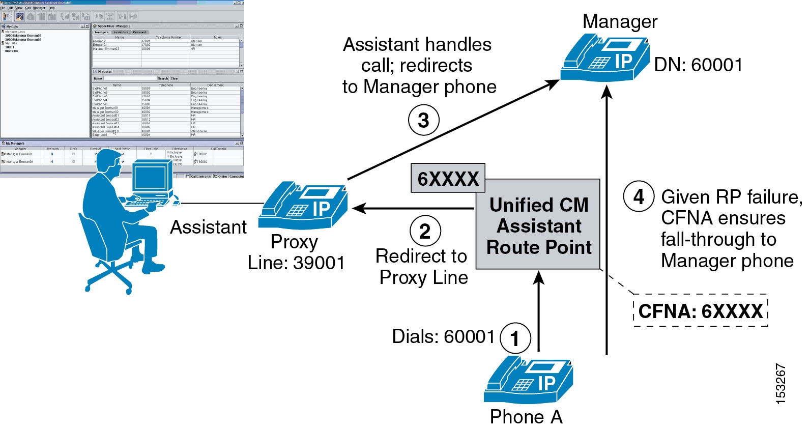
Figure 22-5 illustrates a simple call flow with Unified CM Assistant in proxy line mode. In this example, Phone A calls the Manager phone with directory number (DN) 60001 (step 1). The CTI/Unified CM Assistant Route Point (RP) intercepts this call based on a configured DN of 6XXXX. Next, based on the Manager DN, the call is redirected by the route point to the Manager's proxy line (DN: 39001) on the Assistant's phone (step 2). The Assistant can then answer or handle the call and, if appropriate, redirect the call to the Manager's phone (step 3). In the event of Unified CM Assistant application failure or if the Unified CM Assistant RP fails, a fall-through mechanism exists via the Call Forward No Answer (CFNA) 6XXXX configuration of the RP, so that calls to the Manager's DN will fall-through directly to the Manager's phone (step 4).
Figure 22-5 Unified CM Assistant Proxy Line Mode
Note
Unified CM Assistant Share Lined Mode
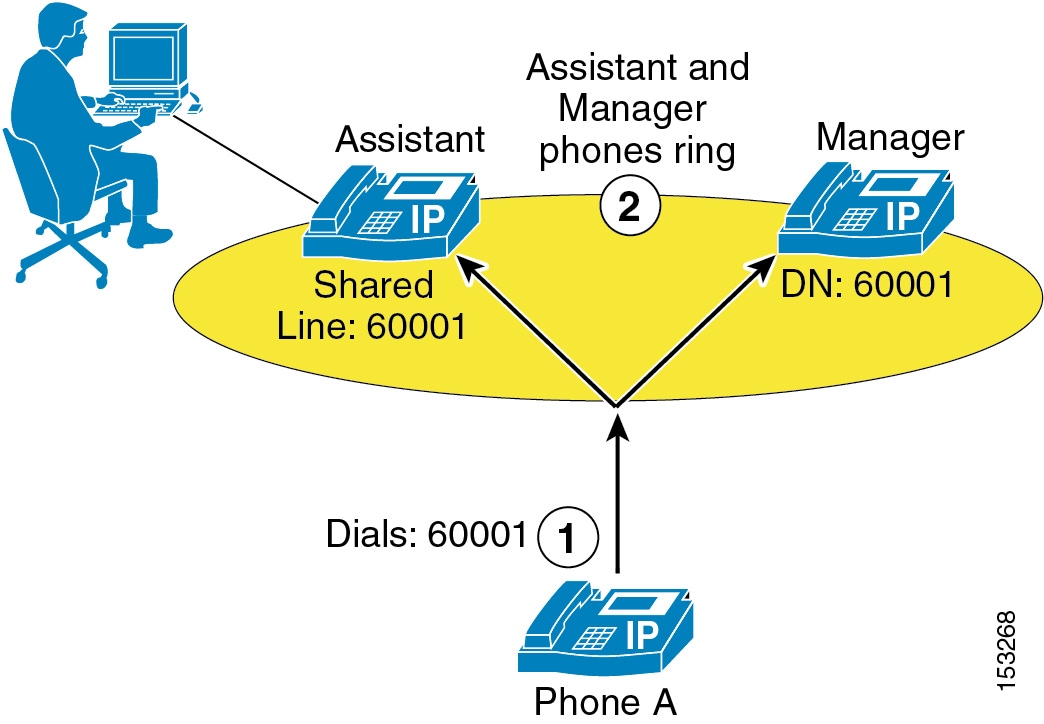
Figure 22-6 illustrates a simple call flow with Unified CM Assistant in shared line mode. In this example, Phone A calls the Manager phone with directory number (DN) 60001, which is a shared line on the Assistant phone (step 1). The call will ring at both the Assistant and Manager phones unless the Manager has invoked the Do Not Disturb (DND) feature, in which case the Assistant's phone will be the only phone that rings audibly (step 2).
Figure 22-6 Unified CM Assistant Shared Line Mode
In Unified CM Assistant shared line mode, the Unified CM Assistant RP is not needed or required for intercepting calls to the Manager phone. However, the Do Not Disturb (DND) feature on the Manager phone and the Unified CM Assistant Console desktop application still depend on the Unified CM Assistant and Cisco CTIManager services. Furthermore, in Unified CM Assistant shared line mode, features such as call filtering, call intercept, assistant selection, and Assistant Watch are not available.
Unified CM Assistant Architecture
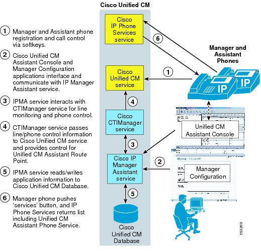
The architecture of the Unified CM Assistant application is as important to understand as its functionality. Figure 22-7 depicts the message flows and architecture of Unified CM Assistant. When Unified CM Assistant has been configured for Unified CM Assistant Manager and Assistant users, the following sequence of interactions and events can occur:
1.
2.
3.
4.
5.
6.
The Unified CM Assistant phone service is controlled by the Unified CM Assistant service, and configuration changes made by the Manager using the phone are handled and propagated via the Unified CM Assistant service.
Note
Figure 22-7 Unified CM Assistant Architecture
Note
Unified CM Assistant Dial Plan Considerations
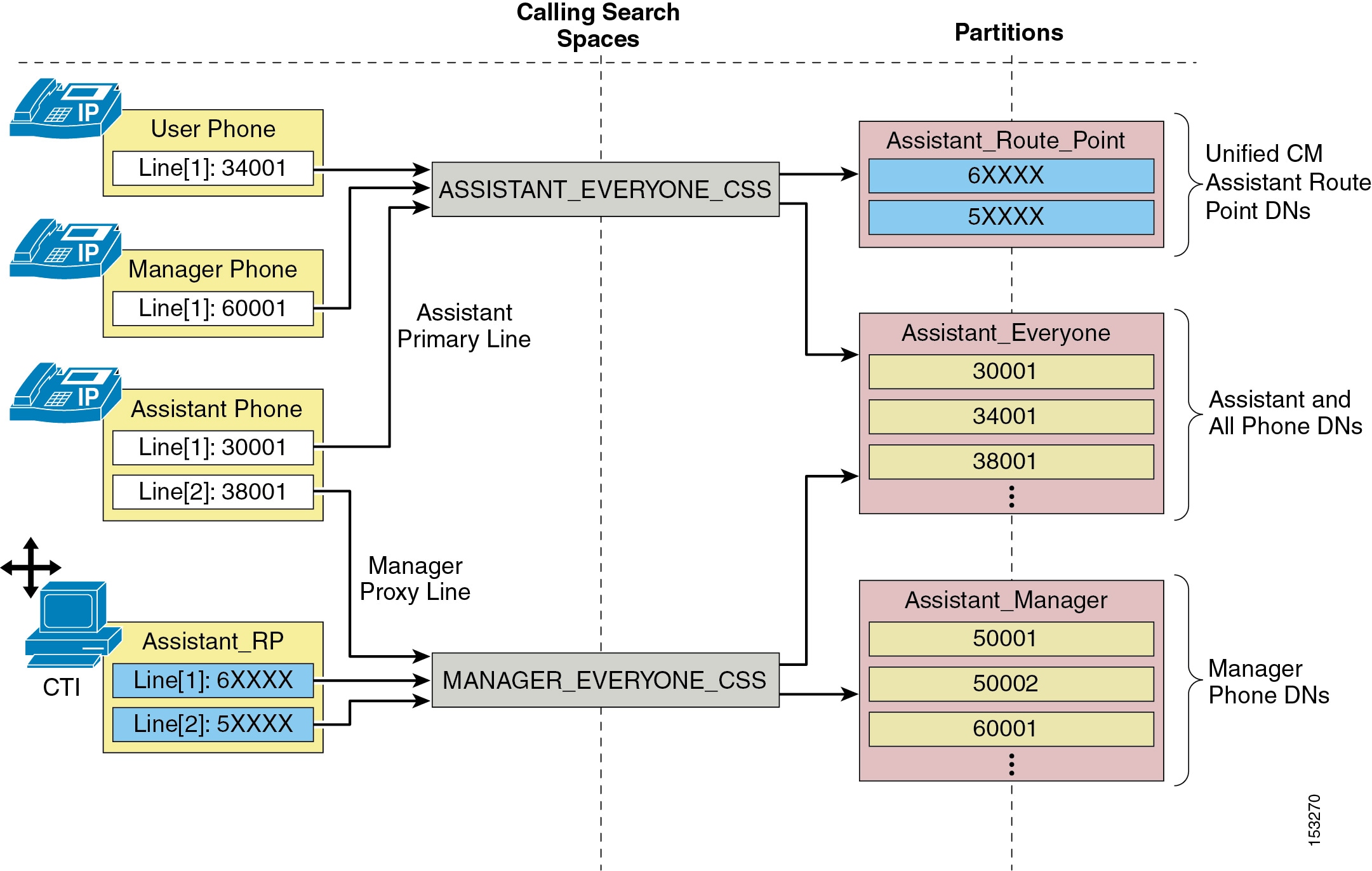
Dial plan configuration is extremely important for Unified CM Assistant configured in proxy line mode. To ensure that calls to Manager DNs are intercepted by the Unified CM Assistant RP and redirected to the Assistant phone, calling search spaces and partitions must be configured in such a way that Manager DNs are unreachable from all devices except the Unified CM Assistant RP and the Manager's proxy line on the Assistant phone.
Figure 22-8 shows an example of a proxy line mode Unified CM Assistant dial plan with the minimum requirements for calling search spaces, partitions, and the configuration of various types of devices within these dial plan components. Three partitions are required for proxy line mode, and for the example in Figure 22-8 they are as follows:
•
•
•
In addition, two calling search spaces are required, and for the example in Figure 22-8 they are as follows:
•
•
That is the extent of the dial plan for this example. However, it is also important to properly configure the various phone and Unified CM Assistant RP DNs or lines with the appropriate calling search spaces so that call routing works as required. In this case all user, Assistant primary (or personal), and Manager phone lines would be configured with the ASSISTANT_EVERYONE_CSS calling search space so that all of these lines can reach all the DNs in the Assistant_Everyone and Assistant_Route_Point partitions. Intercom lines and any other lines configured on devices within the telephony network would be configured with this same calling search space. All Manager proxy lines and all Assistant_RP lines are configured with the MANAGER_EVERYONE_CSS calling search space so that all of these lines can reach the Manager DNs in the Assistant_Manager partition as well as all the DNs belonging to the Assistant_Everyone partition. In this way, the dial plan ensures that only the Assistant_RP lines and the Manager proxy lines on the Assistant phones are capable of reaching the Manager phone DNs directly.
Figure 22-8 Unified CM Assistant Proxy Line Mode Dial Plan Example
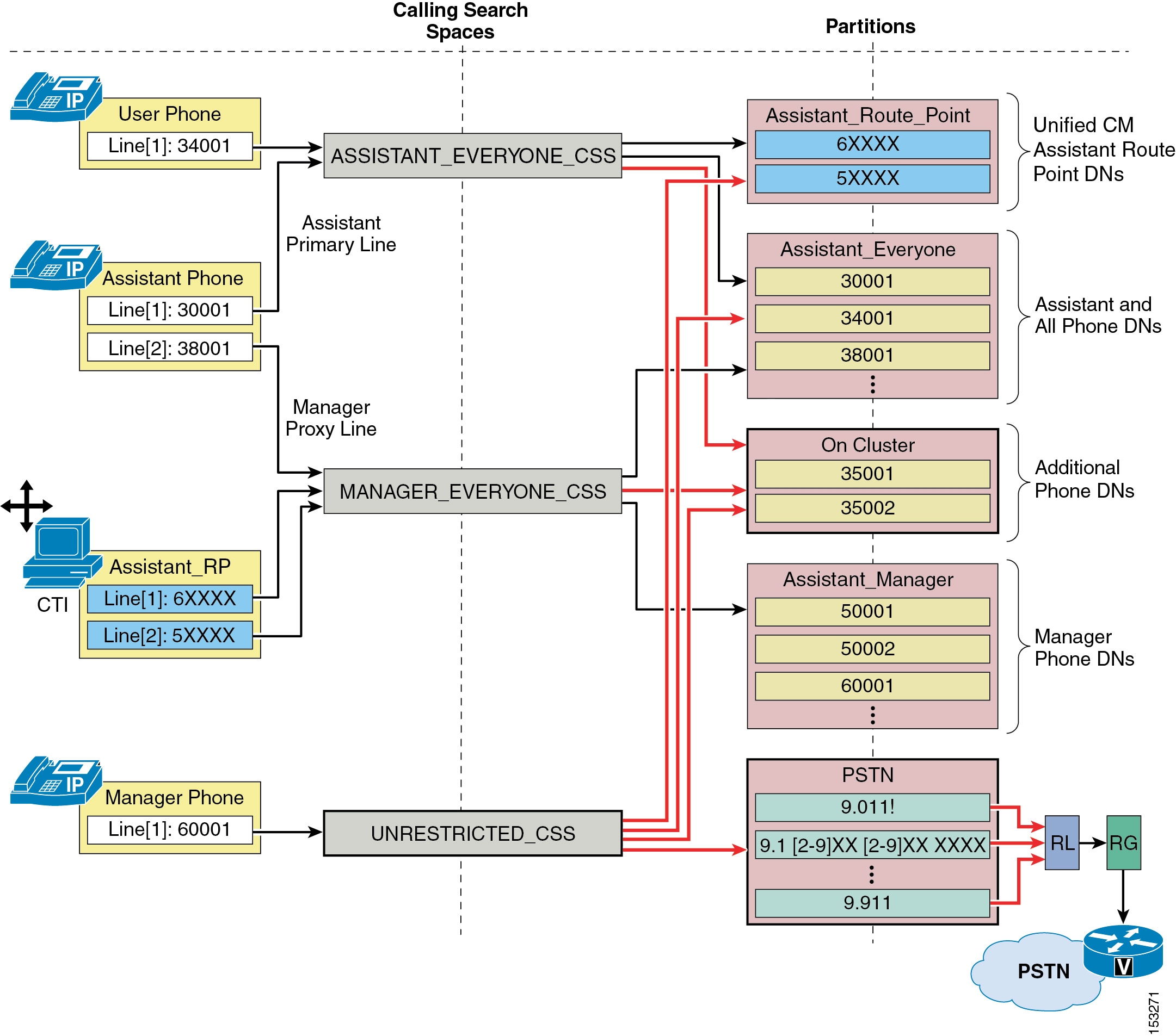
The example in Figure 22-8 shows the minimum dial plan requirements for Unified CM Assistant in proxy line mode. However, most real-world telephony networks will have additional or existing dial plan requirements that must be integrated with the Unified CM Assistant calling search spaces and partitions. Figure 22-9 illustrates such an integration dial plan. In this example, the previously discussed dial plan must now handle two additional partitions and an additional calling search space. The On Cluster partition has been added in Figure 22-9, and it contains some additional phone DNs. The On Cluster partition has been added to both of the existing Unified CM Assistant calling search spaces (ASSISTANT_EVERYONE_CSS and MANAGER_EVERYONE_CSS) so that existing devices can reach these added DNs. The UNRESTRICTED_CSS calling search space has also been added to the existing dial plan. This calling search space is configured with the Assistant_Route_Point, Assistant_Everyone, and the recently added On Cluster partitions. In addition, a second new partition called PSTN has been added, and it contains a set of route patterns used for routing calls to the PSTN via the common route list (RL), route group (RG), and voice gateway mechanism. This PSTN partition is configured as part of the UNRESTRICTED_CSS calling search space.
Phone and device line calling search space configurations may be adjusted to incorporate the newly added partitions and calling search spaces, provided the Assistant_RP and Assistant phone Manager proxy lines remain assigned to the MANAGER_EVERYONE_CSS calling search space. In this example, the Manager phone line has been moved from the originally configured ASSISTANT_EVERYONE_CSS calling search space to the new UNRESTRICTED_CSS because it is likely that a Manager would be given unrestricted access to the PSTN.
Figure 22-9 Unified CM Assistant Proxy Line Mode Dial Plan Integration Example
As Figure 22-9 illustrates, integrating additional partitions and calling search spaces into a new or existing Unified CM Assistant dial plan is feasible, but care must be taken to ensure that the underlying proxy line mode mechanism remains intact.
For Unified CM Assistant shared line mode, no special dial plan provisioning is required. Manager and Assistant phones can be configured with calling search spaces and partitions like any other phones in the network because there are no Unified CM Assistant RPs or proxy lines to be concerned about. The only requirement with regard to shared line mode is that the Manager and Assistant DNs must be in the same partition so that shared line functionality is possible.
Unified CM Assistant Console
The Unified CM Assistant Console desktop application or the Unified CM Assistant Console phone service is required in order for assistants to handle calls on a manager's behalf. The desktop application provides assistants with a graphical interface for handling calls, while the phone service provides a menu-driven interface for handling calls. Both the desktop application and the IP phone service allow the assistant to configure the Manager phone and environment and monitor line status and availability. In addition, the desktop application provides other functions such as click-to-dial speed dialing and directory entries, which can also be performed on the assistant phone using the traditional softkey and menu approach.
Unified CM Assistant Console Installation
The Unified CM Assistant Console desktop application can be installed from the following URL:
https://<Server_IP-Address>:8443/ma/Install/IPMAConsoleInstall.jsp
(where <Server_IP-Address> is the IP address of any node in the cluster)
The Unified CM Assistant Console phone service does not require any installation. To enable the Assistant's phone as a console, subscribe the phone to the Unified CM Assistant phone service. (This is the same service to which Manager phones must also be subscribed.)
Unified CM Assistant Desktop Console QoS
After installation, and in order to handle calls on a Manager's behalf, the Assistant must log on to the application by providing userID and password (as configured in the End-user directory on Unified CM) and will have to toggle status to "online" by clicking the Go Online icon or menu item. Once the user is logged in and online, the desktop application communicates with the Unified CM Assistant server at TCP port 2912. The application chooses an ephemeral TCP port when sourcing traffic. Because the Unified CM Assistant server on Unified CM interfaces with the desktop application for call control (generation and handling of call flows), traffic sourced from Unified CM on TCP port 2912 is QoS-marked by Unified CM as Differentiated Services Code Point (DSCP) of 24 or Per Hop Behavior (PHB) of CS3. In this way, Unified CM Assistant phone control traffic can be queued throughout the network like all other call signaling traffic.
In order to ensure symmetrical marking and queuing, the Unified CM Assistant Console application traffic destined for Unified CM TCP port 2912 should also be marked as DSCP 24 (PHB CS3) to ensure this traffic is placed in the appropriate call signaling queues along the network path toward Unified CM and the Unified CM Assistant server. The Unified CM Assistant Assistant Console application marks all traffic as best-effort. This means that you will have to apply an access control list (ACL) at the switch port level (or somewhere along the network path, preferably as close to the console PC as possible) to remark traffic sent by the application PC destined for Unified CM on TCP port 2912 from DSCP 0 (PHB Best Effort) to DSCP 24 (PHB CS3).
Unified CM Assistant Console Directory Window
The directory window within the Assistant Console desktop application enables an assistant to search for end-users in the Unified CM Directory. Search strings entered into the Name field of the directory window are sent to the Unified CM Assistant server, and searches are generated directly against the Unified CM database. Responses to search queries are then sent back to the desktop application by the Unified CM Assistant server.
While the additional traffic generated by directory searches within the desktop application is nominal, this traffic can be problematic in centralized call processing deployments when one or more Unified CM Assistant console applications are running at remote sites. A directory search resulting in a single entry generates approximately one (1) kilobit of traffic from the Unified CM Assistant server to the desktop application. Fortunately, a maximum of 25 entries can be retrieved per search, meaning that a maximum of approximately 25 kilobits of traffic can be generated for each search made by the desktop application. However, if directory searches are made by multiple Unified CM Assistant Console desktop applications across low-speed WAN links from the Unified CM Assistant server, the potential for congestion, delay, and queuing is increased. In addition, directory retrieval traffic is sourced from Unified CM on TCP port 2912, like all other Unified CM Assistant traffic to the desktop. This means that directory retrieval traffic is also marked with DSCP 24 (PHB CS3) and therefore is queued like call signaling traffic. As a result, directory retrieval could potentially congest, overrun, or delay call control traffic.
Note
Given the potential for network congestion, Cisco recommends that administrators encourage Unified CM Assistant Console users to do the following:
•
•
These recommendations are especially important if either of the following conditions is true:
•
•
Unified CM Assistant Phone Console QoS
In order to handle calls on a Manager's behalf using the Unified CM Assistant Phone Console phone service, the Assistant must log on to the service by providing a userID and PIN (as configured in the End-user directory on Unified CM). Once the user is logged in, the phone console service communicates with Unified CM using HTTPS and SCCP. Call control traffic for Unified CM Assistant call generation and call handling is sent between the phone and Unified CM using SCCP. By default this traffic is marked as Differentiated Services Code Point (DSCP) of 24 or Per Hop Behavior (PHB) of CS3, thus ensuring it is queued throughout the network as call signaling traffic, therefore no additional QoS configuration or marking is required.
Unified CM Assistant Redundancy
Unified CM Assistant application redundancy can be provided at two levels:
•
At this level, redundancy must be considered with regard to Unified CM Assistant service or server redundancy and CTIManager service redundancy. Likewise, the lack of publisher redundancy and the impact of this component failing should also be considered.
•
At this level, redundancy should be considered as it relates to Assistant and Manager phones, the Unified CM Assistant route point, and the Unified CM Assistant Console desktop application and phone service, as well as redundancy in terms of Assistant and Manager reachability.
Service and Component Redundancy
As shown in Figure 22-7, Unified CM Assistant functionality is primarily dependent on the Cisco CallManager IP Manager Assistant service and the Cisco CTIManager service. In both cases, redundancy is automatically built-in using a primary and backup mechanism. Two Unified CM Assistant servers (nodes running the Cisco Unified CM Assistant service) can be defined within a single cluster using the Cisco Unified CM Assistant Server (Primary) IP Address and Cisco Unified CM Assistant Server (Backup) IP Address service parameters (see Unified CM Assistant Service Parameters). With the configuration of these parameters, the required Unified CM Assistant service is made redundant. Given a failure of the primary Unified CM Assistant server, the backup or standby Unified CM Assistant server is able to handle Unified CM Assistant service requests. Only one Unified CM Assistant server can be active and handling request at a given time, while the other Unified CM Assistant server will be in a standby state and will not handle requests unless the active server fails.
In addition, two CTIManager servers or services can be defined for each Unified CM Assistant server using the CTIManager (Primary) IP Address and CTIManager (Backup) IP Address service parameters (see Unified CM Assistant Service Parameters). This results in a total of up to four CTIManagers per cluster for use by the Unified CM Assistant application. By configuring these parameters, you can make the CTIManager service redundant. Thus, given a failure of a primary CTIManager, CTIManager services can still be provided by the backup CTIManager. If all Unified CM Assistant and CTIManager services on cluster nodes fail, the Unified CM Assistant route point, Unified CM Assistant Console desktop application and phone service, and in turn the Unified CM Assistant application as a whole will fail. However as noted previously, given a failure of the Unified CM Assistant application, the CFNA fall-through mechanism will continue to work, allowing calls to a Manager to be routed directly to the Manager's phone.
Note
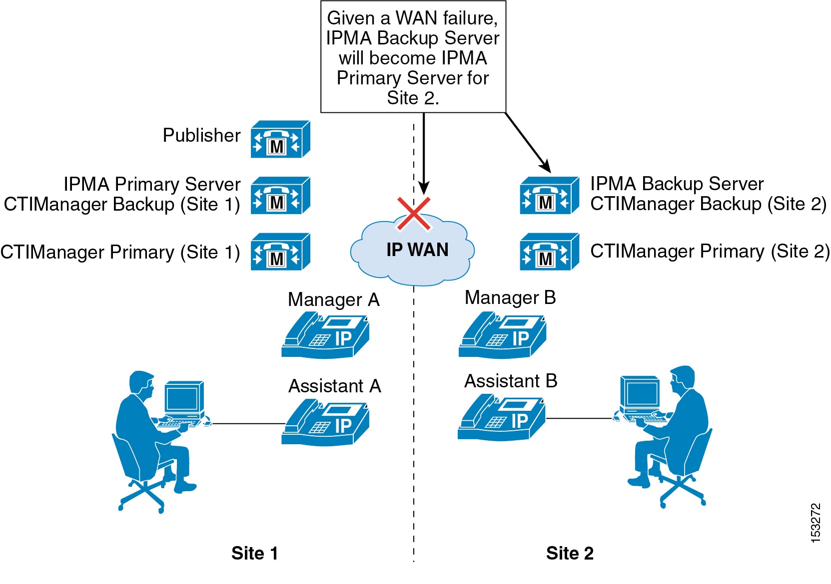
Figure 22-10 shows an example redundancy configuration for Unified CM Assistant and CTIManager primary and backup servers in a two-site deployment with clustering over the WAN. In order to provide maximum redundancy, a node at Site 1 is configured as the primary Unified CM Assistant server and a node at Site 2 is configured as the backup Unified CM Assistant server. In the event of a WAN failure, the backup Unified CM Assistant server at Site 2 will become a primary Unified CM Assistant server because the existing primary Unified CM Assistant server will be unreachable from Site 2. In this way, Unified CM Assistant servers can be made redundant in the clustering-over-the-WAN environment given a WAN failure. Furthermore, with a primary and backup CTIManager configured at both Site 1 and Site 2, CTIManager is made redundant given a WAN failure, and additional redundancy is provided for a CTIManager failure at each site.
Note
Figure 22-10 Unified CM Assistant Redundancy with Two-Site Clustering over the WAN
As previously mentioned, the publisher is a single point of failure when it comes to writing to the Unified CM Database. The effect of a publisher failure on the Unified CM Assistant application is less dramatic than the impact such a failure has on Extension Mobility. Given a publisher failure, all aspects of the Unified CM Assistant application will continue to work; however, no changes to the Unified CM Assistant application configuration can be made. Configuration changes via the Unified CM Assistant Console desktop application, the Manager configuration web-based application, the phone softkeys, or the Unified CM Assistant phone service, will not be possible until the publisher is restored. This condition includes enabling or disabling features such as Do Not Disturb, DivertAll, Assistant Watch, and call filtering, as well as changing call filter and assistant selection configuration.
Device and Reachability Redundancy
Redundancy for Unified CM Assistant at the devices level relies on a number of mechanisms. First and foremost, manager and assistant phones as well as the Unified CM Assistant RP rely on the built-in redundancy provided by a combination of the device pool and Unified CM group configuration for device registration.
In addition, some devices rely on component services for additional redundancy and functionality. For example, the Unified CM Assistant RP also relies on CTIManager for call control functionality and therefore must rely on the primary and back CTIManager mechanism described in the previous section. The Unified CM Assistant Console desktop application also relies on the component services for redundancy and functionality. The Assistant Console desktop application supports automatic failover from the primary to the backup Unified CM Assistant server (and vice versa) in order to continue to handle incoming calls for managers. The amount of time this automatic failover will take can be controlled using the Cisco Unified CM Assistant Console Heartbeat Interval and the Cisco Unified CM Assistant Console Request Timeout service parameters (see Unified CM Assistant Service Parameters). Although the heartbeat or keep-alive frequency can be configured so that failures of the Unified CM Assistant server are detected by the desktop application more quickly, be careful not to affect the network adversely by sending keep-alives too frequently. This consideration is especially important if there are a large number of Assistant Console desktop applications in use.
The Unified CM Assistant Console phone service, unlike the Unified CM Assistant Console desktop application, requires manual intervention for redundancy given the failure of the primary Unified CM Assistant server. If the Primary Unified CM Assistant server goes down, assistants using the phone console will not see an indication of this condition. However, the assistant phone will receive a "Host not found Exception" message upon trying to use a softkey. In order to continue using the phone console with the backup Unified CM Assistant server, the user must manually select the secondary Unified CM Assistant phone service from the IP Services menu and log in again.
There are several other failover mechanisms which ensure that Manager and Assistant reachability are redundant. First, calls sent to a Manager's Assistant via the Unified CM Assistant application (in proxy line mode) can be forwarded to the Manager's next available Assistant if the call is not answered after a configured amount of time. If the next Assistant does not answer the call after the configured amount of time, the call can again be forwarded to the Manager's next available Assistant, and so on. The mechanism is configured using the Cisco Unified CM Assistant RNA Forward Calls and Cisco Unified CM Assistant RNA Timeout service parameters (see Unified CM Assistant Service Parameters). Second, as mentioned previously, if all Unified CM Assistant and CTI services on cluster nodes fail, the Unified CM Assistant RP will become unavailable. However, based on the CFNA configuration of the Unified CM Assistant RP, calls to all Manager DNs will fall-through directly to the Manager phones so that Manager reachability is sufficiently redundant.
Guidelines and Restrictions for Unified CM Assistant
Unified CM Assistant has the following limitations with regard to overlapping and shared extensions, which you should keep in mind when planning directory number provisioning:
•
•
Additionally, Unified CM Assistant assistants should be made aware that, when upgrading from Cisco Unified CM release 4.x to Unified CM 5.x, the Unified CM Assistant Assistant Console desktop application will not automatically upgrade to the newest version. Instead, the previous version of the Unified CM Assistant Console desktop application will have to be un-installed and the new one will have to be installed.
Unified CM Assistant Performance and Capacity
The Cisco Unified CM Assistant application supports the following capacities:
•
•
•
•
•
The Cisco Unified CM Assistant application interacts with the CTIManager for line monitoring and phone control. Each line on a Unified CM Assistant or Manager phone generates a connection to the CTIManager. In addition, each Unified CM Assistant route point generates a connection to the CTIManager. When you configure Unified CM Assistant, the number of required CTI connections must be considered with regard to the overall cluster limit for CTI connections (10,000 CTI connections per cluster with the MCS-7845 platform or 3200 CTI connections per cluster with the MCS-7835 and MCS-7825 servers). If additional CTI connections are required for other applications, they can limit the capacity of Unified CM Assistant.
For additional information on Unified CM Assistant capacity, refer to the Unified CM and Unified CM Assistant data sheets, documentation, and release notes available at
Unified CM Assistant Interactions with EM
Unified CM Assistant Managers can use EM to log in to their phones in both proxy-line and shared-lined modes. However, the Manager must be configured as a Mobile Manager under the Cisco Unified CM Assistant Manager configuration page of the End-user Directory. When using EM in conjunction with Unified CM Assistant, users should not be able to log in to more than one phone using EM. This behavior can be enabled/disabled via the EM service parameter Multiple Login Behavior (see EM Service Parameters). If multiple EM logins by the same user are required within the cluster, Unified CM Assistant Managers who use EM should be instructed not to log in to multiple phones. Allowing a manager to log in to two different phones with EM violates the previously stated restriction that, in proxy line mode, two Managers cannot have the same Unified CM Assistant controlled line number (DN), even across different partitions.
Note
Attendant Console
The Cisco Unified Communications Manager Attendant Console (AC) application enables a receptionist to answer and transfer or dispatch calls within an organization. The attendant can install the attendant console, a client/server Java application, on a PC that runs Windows 2000 or Windows XP. The attendant console connects to the Cisco CallManager Attendant Console Server (Cisco Unified CallManager AC Server) for login services, line state, and directory services. Multiple attendant consoles can connect to a single AC server.
AC Phone Support
The following SCCP phones support AC functionality:
•
•
•
•
•
•
•
Beginning with Cisco Unified Communications Manager release 5.1.1(b), the Cisco Unified IP Phones 7942G, 7945G, 7962G, 7965G, and 7975G also support AC functionality.
AC is not supported on SIP phones.
Unified CM Services and AC Service Parameters
To enable the AC application, the system administrator must activate and start a number of Unified CM feature services from the Unified CM Serviceability interface. In addition, AC service parameters provide configuration and customization options for determining how the AC application behaves.
Unified CM Services for AC
The AC application relies on the following feature services, which must to be activated manually from the Serviceability page:
•
•
The Cisco CallManager Attendant Console Server service provides an interface for the AC Desktop application and interacts with the Cisco CTIManager service and Unified CM database. The Cisco CTIManager service interfaces and interacts with the Cisco CallManager Service and the Cisco CallManager Attendant Console Server service for phone and call control. It also interfaces with the AC Desktop application.
AC Service Parameters
The following items represent a partial list of Cisco CallManager Attendant Console Server Service Parameters related to AC functionality:
•
This parameter specifies the frequency interval, in hours, for the synchronization of the AC server AutoGenerated.txt file with the Unified CM End-user Directory. Changes to the End-user Directory will not be reflected in the AutoGenerated.txt file until this interval is reached.
•
This parameter specifies the application user name that the AC server uses to log into and communicate with the CTIManager.
•
This parameter specifies the application user name that the AC server uses for authentication of the attendant phone.
For a complete list of Attendant Console service parameters, refer to the Unified CM Attendant Console information in the Cisco Unified Communications Manager Features and Services Guide, available at
http://www.cisco.com/en/US/products/sw/voicesw/ps556/prod_maintenance_guides_list.html
AC and AC Device Authentication Application Users
For proper AC operation, an application user named ac must be configured in Unified CM. The ac application user is required in order for the AC server to interact with the CTIManager. Without this application user configuration, attendants will not be able to receive calls.
Note
The ac user must be configured with the following group permissions under the application user configuration page:
•
•
•
By configuring the ac application user with the "Standard CTI Allow Control of All Devices" group permissions, you enable the CTI Super Provider feature. The Super Provider feature allows the AC application to control and monitor (via CTI) any device or line, which eliminates the need for associating attendant phones and AC pilot points to the ac application user, thus greatly simplifying configuration.
An administrator might want to change this application user name to something other than ac. If a user name other than ac is configured, the JTAPI Username service parameter (see AC Service Parameters) must be set to the new user name.
In addition to adding the ac user and assigning the group permissions listed above, you should create a device authentication application user named ACDeviceAuthenticationUser. Once configured, all attendant phones must be associated with this application user. This application user is used by the Cisco Unified CM Attendant Console server to authenticate attendant phones. No group permissions need to be configured for this application user account.
If an administrator chooses to use a different application user account name instead of ACDeviceAuthenticationUser, the Device Authentication Application Username service parameter (see AC Service Parameters) must be changed to match the configured application user name.
AC Functionality and Architecture
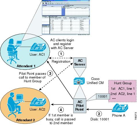
Figure 22-11 illustrates a basic example of AC functionality and operation. First, the AC clients log into and registered with the AC server on Unified CM (step 1). Next, Phone A calls directory number (DN) 10001 configured for the AC pilot point on Unified CM (step 2). The AC pilot point intercepts this call and, based on the hunt group configuration, directs the call to one of its available members. In this case, the call is sent to line 2 of the Attendant user AC1's phone (step 3). If a second call comes into the pilot point number 10001 while user AC1 is still on the first call, the second call is routed to another available member of the hunt group, and in this case the call is forwarded to line 1 of Attendant user AC2's phone (step 4).
Figure 22-11 Basic AC Operation
For purposes of routing calls, pilot points determine the next available member of a hunt group based on one of the following routing algorithms (configured in the "Route Calls to" field under the pilot point):
•
With this algorithm, incoming calls are routed to the first member of the group who is available.
•
With this algorithm, incoming calls are routed to the member who has been idle (not handled a call) the longest.
•
With this algorithm, incoming calls are routed to the available members in a round-robin fashion.
•
With this algorithm, incoming calls are queued, and indication is sent to the AC desktop application of all available members simultaneously.
With the example shown in Figure 22-11, the First Available algorithm is used. The hunt group routing algorithm as well as the queuing settings for the Broadcast routing algorithm are all configured under the Pilot Point configuration page on Unified CM.
AC Architecture
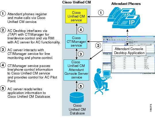
The architecture of the AC application is as important to understand as it functionality. Figure 22-12 depicts the message flows and architecture of AC. When AC has been configured for AC users, the following sequence of interactions and events can occur:
1.
2.
3.
4.
5.
Figure 22-12 AC Architecture
Note
Attendant Console Desktop Application
The Attendant Console desktop application is used by attendants to handle calls via a graphical virtual console. Besides call handling, the application provides additional functions such as click-to-dial speed dialing and directory entries, environment configuration, and line status and availability indication for other users within the directory and speed dial windows.
Attendant Console Installation
The Attendant Console desktop application can be downloaded from the following URL:
https://<Server_IP-Address>:8443/plugins/CiscoAttendantConsoleClient.exe
(where <Server_IP-Address> is the IP address of any node in the cluster)
Once the CiscoAttendantConsoleClient.exe file has been downloaded to an attendant's PC, it must also be installed.
Attendant Console QoS
After installing the Attendant Console desktop application, an attendant logs on to the console application by providing an AC userID and password (as configured under the Cisco Unified CM Attendant Console User page on Unified CM).
Note
Once the AC user is logged on, the AC desktop application communicates with Unified CM using Remote Method Invocation (RMI) and Java Telephony Application Programming Interface (JTAPI) protocols predominantly. RMI is used for communication between the, desktop client and the AC server including registration, keep-alives, and information exchange. RMI traffic is sourced from Unified CM on TCP ports 1101 to 1129 and sourced from the desktop application on one or more ephemeral TCP ports. All RMI traffic is marked as best-effort.
JTAPI traffic carries device and line control information and call control traffic between the CTIManager on Unified CM and the AC desktop application. JTAPI Traffic is sourced from Unified CM on TCP port 2748 and sourced from the desktop application on an ephemeral TCP port.
Because the JTAPI traffic between the CTIManager and AC client is used for call control (generation and handling of call flows), this traffic is QoS-marked by Unified CM with DSCP of 24 (PHB of CS3). In this way, AC phone control traffic can be queued throughout the network like all other call signaling traffic. In order to ensure symmetrical marking and queuing, the Attendant Console desktop application traffic destined for Unified CM TCP port 2748 should also be marked as DSCP 24 (PHB CS3) to ensure this traffic is placed in the appropriate call signaling queues along the network path toward Unified CM and the CTIManager. However, because the AC client application marks all traffic as best-effort, an access control list (ACL) must be configured to re-mark this traffic properly.
The AC server and desktop client marking can be summarized as follows:
•
•
Attendant Console Directory Window
The directory window within the Attendant Console desktop application enables an attendant to search for end-users within the Unified CM telephony environment. Typically directory listings are obtained by searching against a directory file rather than searching against the Unified CM directory itself. One of the following directory files will be searched when an AC application user enters a search in the directory window:
•
This directory file is stored on the local PC or on a local drive path. In order for this file to be searched, its name and location must be configured in the Path Name of Local Directory File field under the Advanced tab of the Attendant Settings dialog box. If a file name and location has not been configured in this field, this option is skipped and a directory search will be conducted against one of the other directory files.
•
This directory file is automatically generated from the Unified CM database end-user table by the AC server and is stored on the Unified CM server. If the local directory user list file is not configured, then the AC desktop application will download this file from Unified CM automatically. The AutoGenerated.txt file is periodically regenerated or synchronized by the AC server against the end-user directory to ensure that the information in the file is accurate. The frequency of this synchronization is determined by the Directory Sync Period AC service parameter (see AC Service Parameters), which by default is set to three hours, meaning that the AutoGenerated.txt file will be updated every three hours.
•
This file is available only if manually imported to Unified CM by an Administrator using the Cisco Unified CM Attendant Console User File Upload tool (under Application > Cisco Unified CM Attendant Console). If uploaded, this file will replace the AutoGenerated.txt file on the Unified CM server. Therefore, the AC desktop application will download this file rather than the AutoGenerated.txt file, provided that the local user list file has not been configured.
One of the directory files listed above is downloaded (in the case of the AutoGenerated or Corporate Directory.txt files) and loaded every time the AC desktop application is launched. The directory file is then downloaded and/or reloaded periodically, as long as the application is up, based on the Directory Reload Interval setting on the Advanced tab of the Attendant Settings dialog box. All the directory files conform to a comma-delimited format with one user entry per line.
While the additional traffic generated by downloading directory files for directory window searches within the desktop application is typically nominal, this traffic can be problematic for a number of reasons. First, if the Unified CM directory size is large, the directory file downloaded by the console application containing the entire directory can generate large amounts of traffic on the network. When this factor is coupled with large numbers of AC desktop applications within the network, short download intervals, a centralized call processing deployment, and console applications running at remote sites over low-speed WAN links, the potential for network congestion, delay, and queuing is highly probable.
Although the use of local user list files on the desktop application PCs could likely eliminate many of the concerns about network bandwidth and congestion, the Advanced search feature within the directory window of the AC desktop is more problematic. Whereas all other directory searches within the AC desktop application directory window are conducted against either the local user list file or one of the downloaded files, there is an exception for searches done using the Advanced search window triggered by the Advanced button in the directory window. Searches made using the Advanced search window bypass the directory file search convention and instead are generated directly against the Unified CM end-user directory in real time. This means additional traffic on the network above and beyond the periodic downloading of directory files. Furthermore, there is no limit on the number of entries that can be downloaded using the Advanced search feature. Not only will these real-time searches and retrievals generate additional network load, but because there is no limiting of returned entries, this additional load can be quite large. Fortunately, the traffic generated by both the directory file download and the Advanced directory search use the RMI protocol, which is marked as best-effort, so there is no risk of congesting priority voice media and provisioned call signaling queues on the network path. However, the possibility still exists that the AC desktop application directory traffic could cause congestion of the best-effort queues and lead to dropping of both directory traffic and other best-effort network data traffic.
Given the potential for network congestion with AC desktop application directory file downloads and directory searches, Cisco recommends the following practices:
•
•
These recommendations are especially critical if one or more of the following conditions are true:
•
•
•
AC Redundancy
AC application redundancy can be provided at two levels:
•
At this level, redundancy must be considered with regard to AC service or server redundancy and CTIManager service redundancy. Likewise, the lack of publisher redundancy and the impact of this component failing should also be considered.
•
At this level, redundancy should be considered as it relates to attendant phones, the AC pilot point, and the Attendant Console desktop application, as well as redundancy in terms of attendant and pilot point reachability.
Service and Component Redundancy
As shown in Figure 22-12, AC functionality is primarily dependent on the Cisco CallManager Attendant Console Server service and the Cisco CTIManager service. In both cases, redundancy is built into the Unified CM cluster architecture. Redundancy for both the AC Server service and the CTIManager service is determined by the number of nodes within the cluster where each service is running. Redundancy is determined by the number of server failures that can occur while still providing the required service, which can be expressed using the formula (N - 1), where N is the number of servers running the service. For example, if three servers in the cluster are running the AC Server service, then N = 3. Redundancy for this service can then be calculated as (3 - 1), or 2. Thus, redundancy is ensured for up to two server failures. CTIManager redundancy can be calculated using the same formula. In order to provide maximum redundancy for these services, Cisco recommends running both the AC Server and CTIManager services on all call processing nodes within the cluster. However, for minimum redundancy, each of these services should run on at least two call processing nodes within the cluster.
The publisher is a single point of failure when it comes to writing to the Unified CM Database. The affect of a publisher failure on the AC application is minimal. Given a publisher failure, all aspects of the AC application will continue to work; however, no changes to AC application configuration can be made. Configuration changes to AC pilot points, hunt groups, and attendant phones will not be possible until the publisher is restored.
Device and Reachability Redundancy
Redundancy for AC at the device level relies on a number of mechanisms. First and foremost, attendant phones as well as the AC pilot point rely on the built-in redundancy provided by a combination of the device pool and Unified CM group configuration for device registration.
In addition, some devices rely on component services for additional redundancy and functionality. For example, the AC pilot point also relies on CTIManager for call control functionality and must therefore rely on CTIManager redundancy as described in the previous section.
The Attendant Console desktop application also relies on the component services for redundancy and functionality. The AC desktop application supports automatic failover between redundant AC Servers and CTIManager services in order to continue to handle incoming calls. Redundancy of these services from perspective of the AC desktop application is determined by the Unified CM group mechanism as described below. First, when the AC desktop application is launched and the attendant logs in, the application downloads a list of Unified CMs based on the device pool and Unified CM group configuration of the attendant phone. This list is stored in the GlobalSettings.xml file on the local PC and determines CTIManager service redundancy for the desktop.
Note
Next, the desktop application relies on the device pool and Unified CM group of the AC pilot point (of which the attendant phone is a member) for AC server redundancy. In both cases, up to tertiary redundancy is provided because up to three servers can be configured in a Unified CM group.
Further redundancy for these services can be provided for the desktop application via the Call Processing Server Host Names or IP Addresses field under the Advanced tab of the Attendant Settings dialog box. By configuring a comma-separated list of Unified CM servers in this field, additional redundancy beyond the Unified CM group mechanism can be provided. However, because this additional redundancy is useful only if the group mechanism has been exhausted, it might be unnecessary. This additional redundancy would really be used only in the event that the first three servers providing registration services for the attendant phone and AC pilot point are unavailable, which means that the attendant phone and AC pilot point are also unavailable. If the phone and pilot point are unavailable, then the desktop application is of no use.
Finally, besides the reachability redundancy built into the hunt group mechanism under the AC pilot point, which provides incoming callers with attendant redundancy, additional redundancy can be provided for an AC pilot point failure. If an AC pilot point fails, incoming callers dialing the pilot point number will receive a busy tone. In order to provide a failover mechanism for pilot points, another AC pilot point number can be configured in the Call Forward No Answer (CFNA) fields of the pilot point line configuration screen. This CFNA mechanism ensures that callers to a failed pilot point will be forwarded to another pilot point for call handling and routing.
Guidelines and Restrictions for AC
AC is aware of partitions at the JTAPI level, therefore the Attendant Console desktop application is aware of partitions in terms of line control. However, other AC components are not aware of partitions, or they have some limitations with regard to overlapping and shared extensions. Keep the following guidelines in mind when planning directory number provisioning:
•
–
–
–
•
–
–
•
Line status displays within the console directory and speed-dial windows are unable to account for shared lines or overlapping extensions. As a result, only the status of the most recently changed line instance is shown when encountering shared or overlapping line appearances.
Also ensure that all AC pilot points are configured with a calling search space that includes all partition in which hunt group member directory numbers reside. Failure to do so will result in one or more members being unreachable.
AC Performance and Capacity
The Cisco AC application supports the following capacities:
•
•
•
•
•
•
•
•
Note
In order to support the maximum of 500 attendants and 500 pilot points, attendants and pilot points must be distributed across multiple servers in groups of no more than 125 pairs per MCS-7845 server, no more than 100 pairs per MCS-7835 server, and no more than 75 pairs per MCS-7825 server.
The Cisco AC application interacts with the CTIManager for line monitoring and phone control. Each line on an Attendant phone generates a connection to the CTIManager. In addition, each AC pilot point generates a connection to the CTIManager. When you configure the AC application, the number of required CTI connections must be considered with regard to the overall cluster limit for CTI connections (10,000 CTI connections per cluster with the MCS-7845 platform or 3200 CTI connections per cluster with the MCS-7835 and MCS-7825 servers). If additional CTI connections are required for other applications, they can limit the capacity of the AC application.
AC Interactions with EM
AC Console users can log in to their phones using EM. However, the AC desktop application requires AC users to log out and back into the application whenever there is a configuration change on the attendant phone. Because an EM login (or logout) results in a configuration change on the phone, when using AC and EM together, users should first log in to their phone using EM and then log in to the AC desktop application, thus eliminating the need to log out and back on to the desktop application.
In addition, EM and AC user DNs should be added to AC pilot point hunt groups as User Members rather than Device Members. This practice ensures that incoming calls will not be routed to an AC user who is unavailable due to the fact that they are not logged into their phone using EM. User Members of a hunt group are configured with both a user name and line number, while Device Members are simply configured with a directory number. The pilot point routes calls to Device Members after checking to see only that the directory number is not busy. The pilot point routes calls to User Members after verifying that the line number of the attendant phone is available and that the AC user is logged on and online. Thus, by adding EM AC users to a hunt group as User Members, you can ensure that a call will be sent to that user phone only if the EM AC user is logged in.
WebDialer
WebDialer is a click-to-dial application for Unified CM that enables users to place calls easily from their PCs using any supported phone device. There is no requirement for administrators to manage CTI links or build JTAPI or TAPI applications because Cisco WebDialer provides a simplified web application and HTTP or Simple Objects Access Protocol (SOAP) interface for those who want to provide their own user interface and authentication mechanisms. Either way, the solution scales to support the entire Unified CM cluster with full redundancy.
WebDialer Phone Support
The following SCCP phones support WebDialer:
•
•
•
•
•
•
•
•
•
•
The following SIP phones also support WebDialer:
•
•
•
Beginning with Cisco Unified Communications Manager release 5.1.1(b), the Cisco Unified IP Phones 7942G, 7945G, 7962G, 7965G, and 7975G running SCCP or SIP loads also support WebDialer.
Note
Unified CM Services and WebDialer Service Parameters
To enable the WebDialer application, the system administrator must activate and start a number of Unified CM feature services from the Unified CM Serviceability interface. In addition, WebDialer service parameters provide configuration and customization options for determining how the WebDialer application and services behave.
Unified CM Services for WebDialer
The WebDialer application relies on the following feature services, which must be activated manually from the Serviceability page:
•
•
The Cisco WebDialer Service is the interface point between click-to-dial web-based and desktop-based applications and Unified CM. The Cisco CTIManager Service processes requests received from the WebDialer service by interacting with the Unified CM call processing and database layers. The net result exposes phone and call control capabilities to the applications.
WebDialer Service Parameters
The following items represent a partial list of Cisco WebDialer Web Service service parameters related to WebDialer functionality:
•
This parameter determines whether a secure Transport Layer Security (TLS) connection is used between the Cisco WebDialer Web service and the CTIManager. If enabled, a secure connection is configured using the Certificate Authority Proxy Function (CAPF) profile configured for the instance ID of the application user WDSecureSysUser. The instance ID must be specified under the CAPF Profile Instance ID for Secure Connection to CTIManager service parameter.
Note
•
The CAPF Profile Instance ID is a unique string of numbers and/or letters used to identify the TLS connection or instance that is made between the Cisco WebDialer Web service and CTIManager for the WDSecureSysUser application user. If the CTI Manager Connection Security Flag parameter is set to True, then this parameter must be configured with a value.
•
This parameter specifies the IP address of the Unified CM subscriber running the CTIManager service that WebDialer should use when processing requests. This is a cluster-wide parameter.
•
This parameter specifies the IP address of the Unified CM subscriber running the backup instance of the CTIManager service that WebDialer should use when processing requests. This is a cluster-wide parameter.
•
This parameter specifies the IP address and port numbers of all WebDialers in the enterprise. Use a space to separate multiple entries. This parameter must be populated if Redirector functionality is needed.
•
This parameter specifies the time in hours after which the user session or browser cookie will expire. A value of 0 indicates that the session or cookie will never expire.
For a complete list of WebDialer service parameters, refer to the Cisco WebDialer information in the Cisco Unified Communications Manager Features and Services Guide, available at
http://www.cisco.com/en/US/products/sw/voicesw/ps556/prod_maintenance_guides_list.html
WebDialer Functionality and Architecture
The WebDialer application contains two servlets: the WebDialer servlet and the Redirector servlet. The operation and functionality of each servlet is similar, and they can be configured to run simultaneously.
WebDialer Servlet
Figure 22-13 illustrates a simple WebDialer example. In this example, user John Smith launches WebDialer via a web-based or desktop application (step 1). WebDialer responds with a request for login credentials. The user must respond with a valid userID and password as configured in the Unified CM end-user directory. In this case, John Smith submits userID = jsmith and password = cisco (step 2). Next, based on this login, WebDialer responds with the Cisco WebDialer Preferences configuration page, and the user must indicate either "User permanent device" or "Use Extension Mobility" (assuming the user has an EM device profile). In this case, user John Smith selects "User permanent device" and selects the appropriate MAC address (SEP00036BC7B973) and directory number (10001) for his phone from drop-down menus on the configuration page (step 3). Finally, the user is presented with a screen requesting the phone number to be called (this value may already be indicated) and must click Dial. In this case, John Smith enters 10002 and, after clicking Dial, a call is automatically generated from his phone to Phone B at number 10002 (step 4).
Note
Figure 22-13 WebDialer Servlet Operation
Redirector Servlet
The Redirector servlet provides WebDialer functionality in a multi-cluster or distributed call processing environment. This functionality allows the use of a single enterprise-wide web-based WebDialer application between all Unified CM clusters. Figure 22-14 illustrates the basic operation of the Redirector servlet as part of the WebDialer application. In this example, the enterprise has three Unified CM clusters: New York, Chicago, and San Francisco. All three clusters have been configured with a single WebDialer application. The San Francisco cluster has been designated as the Redirector. In order to designate the San Francisco WebDialer as the enterprise-wide Redirector, each cluster WebDialer server must have the service parameter List of WebDialers (see WebDialer Service Parameters) configured with its own IP address and the San Francisco WebDialer IP address. The San Francisco WebDialer server will be configured with its own IP address and the addresses of all other WebDialer servers in the enterprise. Based on this example, the List of WebDialers service parameter field for each WebDialer server would be configured as follows:
•
•
•
The enterprise-wide web-based application points to the San Francisco Redirector and is launched by the New York user (see step 1 in Figure 22-14). Next the Redirector requests user login, and the New York user responds back with their userID and password (see step 2 in Figure 22-14).
Note
The Redirector then broadcasts an isClusterUser HTTPS request to every WebDialer in the enterprise simultaneously (as configured in the List of WebDialers service parameter). In this example, the requests go to the Chicago and New York WebDialer servers (see step 3 in Figure 22-14). Because the New York user is local to the New York cluster, the New York WebDialer responds with a positive response (see step 4 in Figure 22-14). Finally, the New York user is redirected to their local WebDialer server, which will handle the application request (see step 5 in Figure 22-14). The user is not notified of the redirect; however, the URL in the browser address bar will be changed as the user is redirected from the Redirector to the local WebDialer server).
Figure 22-14 Redirector Servlet Operation
Note
WebDialer Architecture
The architecture of the WebDialer application is as important to understand as its functionality. Figure 22-15 depicts the message flows and architecture of WebDialer. The following sequence of interactions and events can occur:
1.
2.
–
This interface is used by web-based applications based on the HTTPS protocol. This is the only interface that provides access to the WebDialer and Redirector servlets.
–
This interface is used by desktop applications based on the SOAP interface.
3.
4.
5.
Figure 22-15 WebDialer Architecture
Note
WebDialer URLs
The WebDialer application can be accessed from web-based applications via the HTML-over-HTTPS interface using the following URLs:
•
https://<Server-IP_Addr>:8443/webdialer/Webdialer?destination=<Number_to_dial>
(where <Server_IP-Address> is the IP address of any node in the cluster running the Cisco WebDialer Web Service service, and where <Number_to_dial> is the number that the WebDialer user wishes to dial)
•
https://<Server-IP_Addr>:8443/webdialer/Redirector?destination=<Number_to_dial>
(where <Server_IP-Address> is the IP address of any node in the enterprise running the Cisco WebDialer Web Service service, and where <Number_to_dial> is the number that the WebDialer user wishes to dial)
Figure 22-16 gives an example of HTML source code used in a click-to-dial web-based application calling the Cisco WebDialer application. In this example, the URL https://10.1.1.1:8443/webdialer/Webdialer?destination=30271 in the HTML source view corresponds to the "Phone: 30721" link for user Steve Smith within the web browser view. A user clicking on this link would launch the WebDialer application and, after logging in and clicking Dial, would generate a call from the user's phone to Steve Smith's phone. The same code could be used for a click-to-dial application using the Redirector function by changing the URL to https://10.1.1.1:8443/webdialer/Redirector?destination=30271.
Figure 22-16 WebDialer URL HTML Example
For information and examples of SOAP-over-HTTP source code to be used in click-to-dial desktop applications, refer to the WebDialer API Programming information in the Cisco Unified Communications Manager Developers Guide, available at
WebDialer Redundancy
WebDialer application redundancy can be provided at two levels:
•
At this level, redundancy must be considered with regard to WebDialer and CTIManager service redundancy. Likewise, the lack of publisher redundancy and the impact of this component failing should also be considered.
•
At this level, redundancy should be considered as it relates to user phones and the WebDialer user interface.
Service and Component Redundancy
As shown in Figure 22-15, WebDialer functionality is primarily dependent on the Cisco WebDialer Web Service and the Cisco CTIManager services. In the case of the WebDialer service, redundancy is provided by listing multiple WebDialer server IP addresses in the List of WebDialers service parameter (see WebDialer Service Parameters) and enabling the service on multiple nodes within the cluster. In the case of CTIManager, redundancy is automatically built-in using a primary and backup mechanism. Two CTIManager servers or services can be defined within the cluster using the Primary Cisco CTIManager and the Backup Cisco CTIManager service parameters (see WebDialer Service Parameters). By configuring these parameters, you can make the CTIManager service redundant. Thus, if the primary CTIManager fails, CTIManager services can still be provided by the backup CTIManager. If the WebDialer server to which the web-based (or desktop) application is pointing fails and the primary and backup CTIManager services on cluster nodes also fail, the WebDialer application will fail. The WebDialer service is not dependant upon the Unified CM publisher
Device and Reachability Redundancy
Redundancy for WebDialer at the device level relies on a number of mechanisms. First and foremost, user phones rely on the built-in redundancy provided by a combination of the device pool and Unified CM group configuration for device registration.
The WebDialer service can run on multiple Unified CM subscribers to provide redundancy, however many applications might not be equipped to handle more than one IP address. Cisco recommends using the Server Load Balancing (SLB) feature available in Cisco IOS to mask the presence of multiple WebDialer servers in the enterprise. The SLB feature provides a virtual IP address or DNS-resolvable hostname that front-ends the real IP addresses of the WebDialer and/or Redirector servers. The SLB feature can be configured to monitor the status of multiple WebDialer servers, automatically redirecting requests during failure events. The SLB feature can also be configured to load-balance WebDialer requests when additional click-to-dial capacity is required. DNS Service (SRV) records can also be used to provide redundancy.
In enterprise deployments, link cost might also be an important consideration. The Cisco Global Site Selector (GSS) feature in Cisco IOS builds upon the capabilities of the SLB feature by adding link cost and availability to the load-balancing algorithm.
Guidelines and Restrictions for WebDialer
The following guidelines and restrictions apply with regard to deployment and operation of WebDialer within the Unified CM telephony environment:
•
–
"No supported device configured for user"
–
"Call to <dialed_ number> failed: User not logged in on any device"
Note
•
•
WebDialer Performance and Scalability
The WebDialer and Redirector services can run on one or more subscriber nodes within a Unified CM cluster, and they support the following capacities:
•
•
Use the following formula to determine the number of WebDialer servers required to handle the user load:
(Number of WebDialer users) * (Average BHCA) / 3600 = Number of calls per second
Note
For example, suppose an organization wishes to enable 3000 users for click-to-dial using WebDialer. Each user is assumed to make 6 calls per hour. Using the formula above, this organization needs to deploy enough WebDialers to handle 5 calls per second:
(3000 WebDialer users) * (6 BHCA) / 3600 = Requirement of 5 calls per second
Because each WebDialer service can make up to 2 calls per second, a total of 3 nodes should be configured to run the WebDialer service in this example.
In order to maintain WebDialer capacity during a server failure, additional backup WebDialer servers should be deployed to provide redundancy.
The Cisco WebDialer application interacts with the CTIManager for phone control. When enabled, each WebDialer service opens a single persistent CTI connection to the CTIManager. In addition, each WebDialer MakeCall request generates a temporary CTI connection. The number of CTI connections required to handle WebDialer call rates must be considered with regard to the overall cluster limit for CTI connections (10,000 CTI connections per cluster with the MCS-7845 platform or 3200 CTI connections per cluster with the MCS-7835 and MCS-7825 servers). If additional CTI connections are required for other applications, they can limit the capacity of the WebDialer application.
WebDialer Interactions with EM
WebDialer users can log in to their phones using EM. EM users wishing to use WebDialer simply need to select the Use Extension Mobility setting under the Cisco WebDialer Preferences page.