- Preface
- Cisco Nexus 5500 Platform Overview
- Installing the Cisco Nexus 5000 Series Switch
- Connecting the Switch
- Replacing Components
- Cabinet and Rack Installation
- Technical Specifications
- Cable and Port Specifications
- LEDs
- Troubleshooting Hardware Components
- Accessory Kits
- Site Planning and Maintenance Records
Installing the Cisco Nexus 5000 Series Switches
This chapter describes how to install the Cisco Nexus 5500 Platform switches and the Cisco Nexus 5000 Platform switches. This chapter includes the following sections:

Note Before you install, operate, or service the system, see the Regulatory Compliance and Safety Information for the Cisco Nexus 5000 Family for important safety information.

Warning IMPORTANT SAFETY INSTRUCTIONS
This warning symbol means danger. You are in a situation that could cause bodily injury. Before you work on any equipment, be aware of the hazards involved with electrical circuitry and be familiar with standard practices for preventing accidents. Use the statement number provided at the end of each warning to locate its translation in the translated safety warnings that accompanied this device.
Statement 1071
Warning This unit is intended for installation in restricted access areas. A restricted access area can be accessed only through the use of a special tool, lock and key, or other means of security.
Statement 1017
Warning Only trained and qualified personnel must be allowed to install, replace, or service this equipment. Statement 1030
Note Each new switch requires a license. For information on licensing, see the Cisco NX-OS Licensing Guide.
Preparing for Installation
This section describes how to prepare the Cisco Nexus 5500 Platform switch or the Cisco Nexus 5000 Platform switch for installation. This section includes the following topics:
- Installation Options with Racks and Cabinets
- Airflow Direction
- Chassis Weight
- Installation Guidelines
- Required Equipment
- Unpacking and Inspecting the Switch
Installation Options with Racks and Cabinets
The Cisco Nexus 5500 Platform switches and the Cisco Nexus 5000 Platform switches can be installed in the following types of racks using a rack-mount kit shipped with the switch:
To enable you to easily mount your switch in any qualifying rack, you can attach the rack-mount brackets to accommodate racks of different depths. For instructions on how to use a rack-mount kit, see the “Installing the Switch” section.
Airflow Direction
The airflow through the fan trays and power supplies on the Cisco Nexus 5548 UP, 5596T, and 5596UP switch is either from front-to-back (port-side exhaust) or from back-to-front (port-side intake), depending on how the modules were ordered. The airflow through the other Cisco Nexus 5000 Series switches is from front-to-back (port-side exhaust). To ensure proper airflow, you must make sure that when you install the switch its air intake is positioned in a cold aisle and the air exhaust is positioned in a hot aisle for your data center.

Caution Only one airflow direction is supported at a time in a Cisco Nexus 5000 Series switch. If a switch has modules for more than one airflow direction an error will occur with possible over heating and shutdown of the switch. If you power up the switch with modules using different airflow directions, you must shutdown the switch and replace the modules with the incorrect airflow direction before powering up the switch.
Note Back-to-front (port-side intake) modules have a black stripe and front-to-back (port-side exhaust) modules do not have a colored stripe.
Chassis Weight
When lifting the switch chassis, follow these guidelines:
- Disconnect all power and external cables before lifting the switch.
- Have two people lift the switch. These switches have the following weights:
– The Cisco Nexus 5596 switch weighs 50 lb (22.68 kg)
– The Cisco Nexus 5548 switch weighs 32 lb (14.51 kg).
Installation Guidelines
When installing the Cisco Nexus 5500 Platform switch or the Cisco Nexus 5000 Platform switch, follow these guidelines:
- Record the information listed in Appendix G, “Site Planning and Maintenance Records,” as you install and configure the switch.
- Ensure that there is adequate space around the switch to allow for servicing the switch and for adequate airflow ( Appendix B, “Technical Specifications,” lists the service and airflow requirements).
- Ensure that the air-conditioning meets the heat dissipation requirements listed in Appendix B, “Technical Specifications.”
- Ensure that the cabinet or rack meets the requirements listed in Appendix A, “Cabinet and Rack Installation.”
Note Jumper power cords are available for use in a cabinet. See the “Jumper Power Cord” section.
- Ensure that the chassis can be adequately grounded. If the switch is not mounted in a grounded rack, we recommend connecting both the system ground on the chassis and the power supply ground directly to an earth ground.
- Ensure that the site power meets the power requirements listed in Appendix B, “Technical Specifications.” If available, you can use an uninterruptible power supply (UPS) to protect against power failures.
Caution Avoid UPS types that use ferroresonant technology. These UPS types can become unstable with systems such as the Cisco Nexus 5500 Platform switches or the Cisco Nexus 5000 Platform switches, which can have substantial current draw fluctuations because of fluctuating data traffic patterns.
- Ensure that circuits are sized according to local and national codes. For North America, the power supply requires a 15-A or 20-A circuit.
Caution To prevent loss of input power, ensure the total maximum loads on the circuits supplying power to the switch are within the current ratings for the wiring and breakers.
- Ensure that all fan trays and power supplies have the same airflow direction. All Cisco Nexus 5000 Series switches can be ordered with front-to-back (port-side intake) airflow and the Cisco Nexus 5596T, 5596UP, and 5548UP switches can alternatively have back-to-front (port-side intake) airflow, which is identified with a black stripe on the switch (front-to-back [port-side exhaust] modules do not have a colored stripe).
- Use the following screw torques when installing the switch:
– Captive screws: 4 in-lb (0.45 N·m)
– M3 screws: 4 in-lb (0.45 N·m)
– M4 screws: 12 in-lb (1.36 N·m)
Required Equipment
Before beginning the installation, ensure that you have the following items available:
- Four 12-24 or 10-32 screws for attaching slider rails to the rack
- Number 1 and number 2 Phillips screwdrivers with torque capability
- 3/16-inch flat-blade screwdriver
- Tape measure and level
- ESD wrist strap or other grounding device
- Antistatic mat or antistatic foam
The following additional items (not found in the accessory kit) are required to ground the chassis:
Unpacking and Inspecting the Switch
Caution When handling switch components, wear an ESD strap and handle modules by their handles and carrier edges only. An ESD socket is provided on the chassis. For the ESD socket to be effective, the chassis must be grounded through the power cable, the chassis ground, or the metal-to-metal contact with a grounded rack.

Tip Keep the shipping container in case the chassis requires shipping in the future.
Note The switch is thoroughly inspected before shipment. If any damage occurred during transportation or any items are missing, contact your customer service representative immediately.
To inspect the shipment, follow these steps:
Step 1 Compare the shipment to the equipment list provided by your customer service representative and verify that you have received all items, including the following:
Step 2 Check for damage and report any discrepancies or damage to your customer service representative. Have the following information ready:
- Invoice number of shipper (see packing slip)
- Model and serial number of the damaged unit
- Description of damage
- Effect of damage on the installation
Installing the Switch
This section includes the following topics:
- Installing a Cisco Nexus 5596 Switch
- Installing the Cisco Nexus 5548 Switch
- Installing the Cisco Nexus 5020 Switch
- Installing the Cisco Nexus 5010 Switch
Installing a Cisco Nexus 5596 Switch
This section describes how to use the rack-mount kit provided with the switch to install the Cisco Nexus 5596UP switch or Cisco Nexus 5596T into a cabinet or rack that meets the requirements described in Appendix A, “Cabinet and Rack Installation.”
Note The Cisco Nexus 5596T and 5596UP switches have either front-to-back (port-side exhaust) or back-to-front (port-side intake) airflow so that you can position either the front or back side of the chassis in the cold aisle so long as it takes in coolant air from the cold aisle.
Caution If the rack is on wheels, ensure that the brakes are engaged or that the rack is otherwise stabilized.
Table 2-3 lists the items contained in the rack-mount kit provided with the switch.
Note You must supply the eight 10-32 or 12-24 screws required to mount the rack brackets and slider rails to the rack. The rack-mount kit does not provide these screws.
To install the switch in a rack or cabinet using the rack-mount kit provided with the switch, follow these steps:
Step 1 Install the front rack-mount brackets on the chassis as follows:
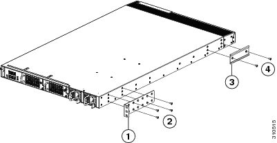
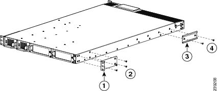
a. Position a front rack-mount bracket on the side of the chassis with its four holes aligned to four of the six screw holes on the front side of the chassis, and then use four M4 screws to attach the bracket to the chassis. See Callouts 1 and 2 in Figure 2-1.
Note You can align any four of the holes in the front rack-mount bracket to four of the six screw holes in the chassis. The holes that you use depend on the requirements of your rack.
Figure 2-1 Attaching Rack-Mount Brackets to the Cisco Nexus 5596 Switch
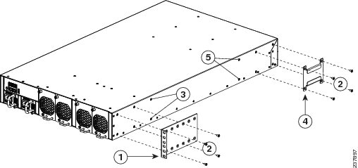
b. Repeat Step 1a with the other front rack-mount bracket on the other side of the switch.
Step 2 Install the rear rack-mount guides on the chassis as follows:
a. Position a rear rack-mount bracket on the side of the chassis with its four holes aligned to four of the six screw holes on the side of the chassis, and then use four M4 screws to attach the bracket to the chassis. See Callout 4 in Figure 2-1.
b. Repeat Step 2a with the other rear rack-mount bracket on the other side of the switch.
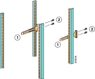
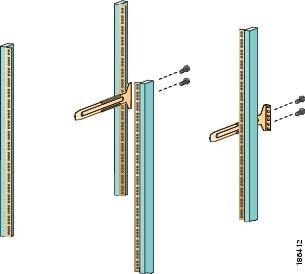
Step 3 Install the slider rails to the rack as follows:
a. Position the slider rails at the desired level on the back side of the rack and use two 12-24 screws or two 10-32 screws, depending on the rack thread type, to attach the rails to the rack. See Figure 2-2.
Note For racks with square holes, you might need to position a 12-24 cage nut behind each mounting hole in a slider rail before using a 12-24 screw.
b. Repeat with the other slider rail on the other side of the rack.
c. Use the tape measure and level to verify that the rails are at the same height and horizontal.
Figure 2-2 Installing the Slider Rails
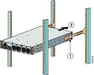
Step 4 Insert the switch into the rack and attach it as follows:
a. Holding the switch with both hands, position the back of the switch between the front posts of the rack.
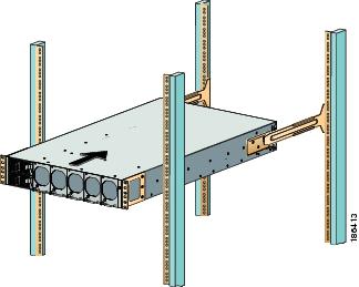
b. Align the two rear rack-mount guides on either side of the switch with the slider rails installed in the rack. Slide the rack-mount guides onto the slider rails, and then gently slide the switch all the way into the rack. See Figure 2-3.
Note If the switch does not slide easily, try realigning the rack-mount guides on the slider rails.
Figure 2-3 Sliding the Chassis Into the Rack
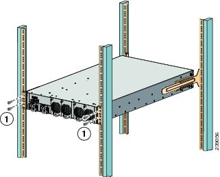
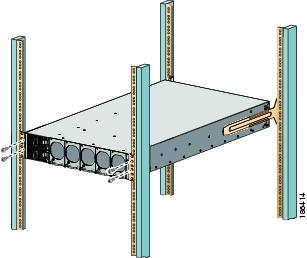
c. Holding the chassis level, insert two screws (12-24 or 10-32, depending on the rack type) through the cage nuts and the holes in one of the front rack-mount brackets and into the threaded holes in the rack-mounting rail. See Figure 2-4.
d. Repeat for the other front rack-mount bracket on the other side of the switch.
Figure 2-4 Attaching the Switch to the Rack
Installing the Cisco Nexus 5548 Switch
This section describes how to use the rack-mount kit provided with the switch to install the Cisco Nexus 5548 switch into a cabinet or rack that meets the requirements described in Appendix A, “Cabinet and Rack Installation.”
Note The Cisco Nexus 5548 can be ordered with front-to-back (port-side exhaust) airflow but the Cisco Nexus 5548UP can be alternatively ordered with back-to-front (port-side intake) airflow. Be sure that the air intake for the chassis is positioned in the cold aisle.
Caution Only one airflow direction is supported at a time in a Cisco Nexus 5000 Series switch (only the Cisco Nexus 5548UP, 5596T, and 5596UP switches support either front-to-back [port-side exhaust] or back-to-front [port-side intake] airflow). If a switch has modules for more than one airflow direction an error will occur with possible over heating and shutdown of the switch. If you power up the switch with modules using different airflow directions, you must shutdown the switch and replace the modules with the incorrect airflow direction before powering up the switch.
Note Back-to-front (port-side intake) modules have a black stripe and front-to-back (port-side exhaust) modules do not have a colored stripe.
Caution If the rack is on wheels, ensure that the brakes are engaged or that the rack is otherwise stabilized.
Table 2-2 lists the items contained in the rack-mount kit provided with the switch.
To install the switch in a cabinet or rack using the rack-mount kit provided with the switch, follow these steps:
Step 1 Install the front rack-mount brackets as follows:
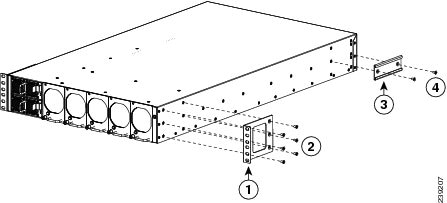
a. Position a front rack-mount bracket against the chassis and align the screw holes as shown in Figure 2-5. Attach the front rack-mount bracket to the chassis with six of the M4 screws.
b. Repeat with the other front rack-mount bracket on the other side of the switch.
Figure 2-5 Attaching the Front Rack-Mount Bracket to the Cisco Nexus 5548 Switch
Four M4 screws used to attach the front rack-mount bracket to the chassis |
Two M4 screws used to attach the rack-mount guide to the chassis |
Step 2 Install the rack-mount guides on the switch as follows:
a. Position one of the rack-mount brackets against the side of the switch and align the screw holes. See Figure 2-5. Attach the bracket to the switch with two of the flat-head M4 screws.
b. Repeat with the other rack-mount bracket on the other side of the switch.
Step 3 Attach the slider rails to the rack as shown in Figure 2-6. Use two 12-24 screws or two 10-32 screws, depending on the rack rail thread type. For racks with square holes, insert the 12-24 cage nuts in position behind the mounting holes in the slider rails.
a. Repeat with the other slider rail on the other side of the rack.
b. Use the tape measure and level to verify that the rails are horizontal and at the same height.
Figure 2-6 Installing the Slider Rails
Step 4 Insert the switch into the rack and attach it as follows:
a. Using both hands, position the switch with the back of the switch between the front posts of the rack.
b. Align the two rack-mount guides on either side of the switch with the slider rails installed in the rack. Slide the rack-mount guides onto the slider rails, and then gently slide the switch all the way into the rack. If the switch does not slide easily, try realigning the rack-mount guides on the slider rails.
Step 5 Stabilize the switch in the rack by attaching the front rack-mount brackets to the front rack-mounting rails:
a. Insert two screws (12-24 or 10-32, depending on the rack type) through the cage nuts and the holes in one of the front rack-mount brackets and into the threaded holes in the rack-mounting rail.
b. Repeat for the front rack-mount bracket on the other side of the switch.
Installing the Cisco Nexus 5020 Switch
This section describes how to use the rack-mount kit provided with the switch to install the Cisco Nexus 5020 switch into a cabinet or rack that meets the requirements described in Appendix A, “Cabinet and Rack Installation.”
Note The Cisco Nexus 5020 can be ordered with front-to-back (port-side exhaust) airflow. Make sure its air intakes are positioned in a cold isle.
Caution If the rack is on wheels, ensure that the brakes are engaged or that the rack is otherwise stabilized.
Table 2-3 lists the items contained in the rack-mount kit provided with the switch.
To install the switch in a cabinet or rack using the rack-mount kit provided with the switch, follow these steps:
Step 1 Install the front rack-mount brackets as follows:
a. Position a front rack-mount bracket against the chassis and align the screw holes as shown in Figure 2-7. Attach the front rack-mount bracket to the chassis with six of the M4 screws.
b. Repeat with the other front rack-mount bracket on the other side of the switch.
Figure 2-7 Attaching Front Rack-Mount Bracket to the Cisco Nexus 5020 Switch
Step 2 Install the rack-mount guides on the switch as follows:
a. Position one of the rack-mount brackets against the side of the switch and align the screw holes as shown in Figure 2-7. Then attach the bracket to the switch with two of the flat-head M4 screws.
b. Repeat with the other rack-mount bracket on the other side of the switch.
Step 3 Attach the slider rails to the rack as shown in Figure 2-8. Use two 12-24 screws or two 10-32 screws, depending on the rack rail thread type. For racks with square holes, insert the 12-24 cage nuts in position behind the mounting holes in the slider rails.
a. Repeat with the other slider rail on the other side of the rack.
b. Use the tape measure and level to verify that the rails are horizontal and at the same height.
Figure 2-8 Installing the Slider Rails
Step 4 Insert the switch into the rack and attach it as follows:
a. Using both hands, position the switch with the back of the switch between the front posts of the rack.
b. Align the two rack-mount guides on either side of the switch with the slider rails installed in the rack. Slide the rack-mount guides onto the slider rails, and then gently slide the switch all the way into the rack. See Figure 2-9. If the switch does not slide easily, try realigning the rack-mount guides on the slider rails.
Figure 2-9 Sliding the Chassis Into the Rack
Step 5 Stabilize the switch in the rack by attaching the front rack-mount brackets to the front rack-mounting rails:
a. Insert two screws (12-24 or 10-32, depending on the rack type) through the cage nuts and the holes in one of the front rack-mount brackets and into the threaded holes in the rack-mounting rail. See Figure 2-10.
b. Repeat for the front rack-mount bracket on the other side of the switch.
Figure 2-10 Attaching the Switch to the Rack
Installing the Cisco Nexus 5010 Switch
This section describes how to use the rack-mount kit provided with the switch to install the Cisco Nexus 5010 switch into a cabinet or rack that meets the requirements described in Appendix A, “Cabinet and Rack Installation.”
Note The Cisco Nexus 5010 can be ordered with front to back airflow. Make sure its air intakes are positioned in a cold isle.
Caution If the rack is on wheels, ensure that the brakes are engaged or that the rack is otherwise stabilized.
Table 2-3 lists the items contained in the rack-mount kit provided with the switch.
To install the switch in a cabinet or rack using the rack-mount kit provided with the switch, follow these steps:
Step 1 Install the front rack-mount brackets as follows:
a. Position a front rack-mount bracket against the chassis and align the screw holes as shown in Figure 2-11. Then attach the front rack-mount bracket to the chassis with six of the M4 screws.
b. Repeat with the other front rack-mount bracket on the other side of the switch.
Figure 2-11 Attaching a Front Rack-Mount Bracket to the Cisco Nexus 5010 Switch
Step 2 Install the rack-mount guides on the switch as follows:
a. Position one of the rack-mount brackets against the side of the switch and align the screw holes as shown in Figure 2-11. Attach the bracket to the switch with two of the flat-head M4 screws.
b. Repeat with the other rack-mount bracket on the other side of the switch.
Step 3 Attach the slider rails to the rack (see Figure 2-12). Use two 12-24 screws or two 10-32 screws, depending on the rack rail thread type. For racks with square holes, insert the 12-24 cage nuts in position behind the mounting holes in the slider rails.
Note You must supply the 12-24 or 10-32 screws.
a. Repeat with the other slider rail on the other side of the rack.
b. Use the tape measure and level to verify that the rails are horizontal and at the same height.
Figure 2-12 Installing the Slider Rails
Step 4 Insert the switch into the rack and attach as follows:
a. Using both hands, position the switch with the back of the switch between the front posts of the rack.
b. Align the two rack-mount guides on either side of the switch with the slider rails installed in the rack. Slide the rack-mount glides onto the slider rails, and then gently slide the switch all the way into the rack. As shown in Figure 2-9, this step is the same as with the step for attaching the Cisco Nexus 5020 to the rack. If the switch does not slide easily, try realigning the rack-mount glides on the slider rails.
Step 5 Stabilize the switch in the rack by attaching the front rack-mount brackets to the front rack-mounting rails:
a. Insert two screws (12-24 or 10-32, depending on rack type) through the cage nuts and the holes in one of the front rack-mount brackets and into the threaded holes in the rack-mounting rail. This procedure is the same as that for the Cisco Nexus 5020 switch (Figure 2-10).
b. Repeat for the front rack-mount bracket on the other side of the switch.
Grounding the Switch
This section describes the need for system grounding for all of the Cisco Nexus 5000 Series switches and explains how to prevent damage from electrostatic discharge.
This section includes the following topics:
- Proper Grounding Practices
- Preventing Electrostatic Discharge Damage
- Establishing the System Ground
- Required Tools and Equipment
- Grounding the Cisco Nexus 5500 Series Chassis
- Grounding the Cisco Nexus 5000 Series Chassis
Proper Grounding Practices
Grounding is one of the most important parts of equipment installation. Proper grounding practices ensure that the buildings and the installed equipment within them have low-impedance connections and low-voltage differentials between chassis. When you properly ground systems during installation, you reduce or prevent shock hazards, equipment damage due to transients, and data corruption. Table 2-5 lists some general grounding practice guidelines.
Note In all situations, grounding practices must comply with local National Electric Code (NEC) requirements or local laws and regulations.
Note Always ensure that all of the modules are completely installed and that the captive installation screws are fully tightened. In addition, ensure that all I/O cables and power cords are properly seated. These practices are normal installation practices and must be followed in all installations.
Preventing Electrostatic Discharge Damage
Electrostatic discharge (ESD) damage, which can occur when modules or other FRUs are improperly handled, results in intermittent or complete failures. Modules consist of printed circuit boards that are fixed in metal carriers. Electromagnetic interference (EMI) shielding and connectors are integral components of the carrier. Although the metal carrier helps to protect the board from ESD, always use an ESD grounding strap when handling modules.
For preventing ESD damage, follow these guidelines:
- Always use an ESD wrist strap and ensure that it makes maximum contact with bare skin.
- ESD grounding straps are available with banana plugs, metal spring clips, or alligator clips. All chassis from the Cisco Nexus 5500 Platform or from the Cisco Nexus 5000 Platform switches are equipped with a banana plug connector (identified by the ground symbol next to the connector) somewhere on the front panel. We recommend that you use a personal ESD grounding strap equipped with a banana plug.
- If you choose to use the disposable ESD wrist strap supplied with most FRUs or an ESD wrist strap equipped with an alligator clip, you must attach the system ground lug to the chassis in order to provide a proper grounding point for the ESD wrist strap.
Note This system ground is also referred to as the network equipment building system (NEBS) ground.
- If your chassis does not have the system ground attached, you must install the system ground lug. See the “Establishing the System Ground” section for installation instructions and location of the chassis system ground pads.
Note You do not need to attach a supplemental system ground wire to the system ground lug; the lug provides a direct path to the bare metal of the chassis.
After you install the system ground lug, follow these steps to correctly attach the ESD wrist strap:
Step 1 Attach the ESD wrist strap to bare skin as follows:
a. If you are using the ESD wrist strap supplied with the FRUs, open the wrist strap package and unwrap the ESD wrist strap. Place the black conductive loop over your wrist and tighten the strap so that it makes good contact with your bare skin.
b. If you are using an ESD wrist strap equipped with an alligator clip, open the package and remove the ESD wrist strap. Locate the end of the wrist strap that attaches to your body and secure it to your bare skin.
Step 2 Grasp the spring or alligator clip on the ESD wrist strap and momentarily touch the clip to a bare metal spot (unpainted surface) on the rack. We recommend that you touch the clip to an unpainted rack rail so that any built-up static charge is then safely dissipated to the entire rack.
Step 3 Attach either the spring clip or the alligator clip to the ground lug screw as follows:
a. If you are using the ESD wrist strap that is supplied with the FRUs, squeeze the spring clip jaws open, position the spring clip to one side of the system ground lug screw head, and slide the spring clip over the lug screw head so that the spring clip jaws close behind the lug screw head.
Note The spring clip jaws do not open wide enough to fit directly over the head of the lug screw or the lug barrel.
b. If you are using an ESD wrist strap that is equipped with an alligator clip, attach the alligator clip directly over the head of the system ground lug screw or to the system ground lug barrel.
To attach the ESD wrist strap to the system ground lug screw for any of the Cisco Nexus 5500 Series switches, clip the grounding wire to the screw that attaches the grounding lug to the switch chassis (see Figure 2-13).
Figure 2-13 Attaching the ESD Wrist Strap to the System Ground Lug Screw
In addition, follow these guidelines when handling modules:
- Handle carriers by available handles or edges only; avoid touching the printed circuit boards or connectors.
- Place a removed component board-side-up on an antistatic surface or in a static-shielding container. If you plan to return the component to the factory, immediately place it in a static-shielding container.
- Never attempt to remove the printed circuit board from the metal carrier.
Caution For safety, periodically check the resistance value of the antistatic strap. The measurement should be between 1 and 10 megohm (Mohm).
Establishing the System Ground
This section describes how to connect a system ground to the Cisco Nexus 5500 Series switch or the Cisco Nexus 5000 Series switch.
You must use the system ground on AC-powered systems if you are installing this equipment in a U.S. or European Central Office.
The system ground provides additional grounding for EMI shielding requirements and grounding for the low-voltage supplies (DC-DC converters) on the modules and is intended to satisfy the Telcordia Technologies requirements for supplemental bonding and grounding connections. You must observe the following system grounding guidelines for your chassis:
- You must install the system ground connection with any other rack or system power ground connections that you make. The system ground connection is required if this equipment is installed in a U.S. or European Central Office.
- You must connect both the system ground connection and the power supply ground connection to an earth ground. The system ground connection is required if this equipment is installed in a U.S. or European Central Office.
- You do not need to power down the chassis because the Cisco Nexus 5000 Series switches are equipped with AC-input power supplies.
Required Tools and Equipment
To connect the system ground, you need the following tools and materials:
- Grounding lug—A two-hole standard barrel lug. This lug supports up to 6 AWG wire. Supplied as part of accessory kit.
- Grounding screws—Two M4 x 8mm (metric) pan-head screws. These screws are supplied as part of the accessory kit.
- Grounding wire—Not supplied as part of accessory kit. The grounding wire should be sized according to local and national installation requirements. Depending on the power supply and system, a 12 AWG to 6 AWG copper conductor is required for U.S. installations. Commercially available 6 AWG wire is recommended. The length of the grounding wire depends on the proximity of the switch to proper grounding facilities.
- No. 1 Phillips screwdriver.
- Crimping tool to crimp the grounding wire to the grounding lug.
- Wire-stripping tool to remove the insulation from the grounding wire.
Grounding the Cisco Nexus 5500 Series Chassis
The chassis has a grounding pad with two threaded M4 holes for attaching a grounding lug. The location of the system ground on the Cisco Nexus 5500 Platform switches is identical to that on the Cisco Nexus 5000 Platform switches.
Note For the procedure on how to ground the Cisco Nexus 5000 Series switch chassis, see the “Grounding the Cisco Nexus 5500 Series Chassis” section.
Warning When installing or replacing the unit, the ground connection must always be made first and disconnected last. Statement 1046
Caution All power supplies must be grounded. The receptacles of the AC power cables used to provide power to the chassis must be the grounding type, and the grounding conductors should connect to protective earth ground at the service equipment.
Warning When installing or replacing the unit, the ground connection must always be made first and disconnected last.
Statement 1046
Caution Grounding the chassis is required if you are using DC power supplies, even if the rack is already grounded. A grounding pad with two threaded M4 holes is provided on the chassis for attaching a grounding lug. The ground lug must be NRTL listed. In addition, the copper conductor (wires) must be used and the copper conductor must comply with NEC code for ampacity.
To attach the grounding lug and cable to the chassis, follow these steps:
Step 1 Use a wire-stripping tool to remove approximately 0.75 inches (19 mm) of the covering from the end of the grounding cable.
Step 2 Insert the stripped end of the grounding cable into the open end of the grounding lug.
Figure 2-14 Grounding a Cisco Nexus 5500 Platform Switch (Cisco Nexus 5596 Shown)
Step 3 Use the crimping tool to secure the grounding cable in the grounding lug.
Step 4 Remove the adhesive label from the grounding pad on the chassis.
Step 5 Place the grounding lug against the grounding pad so that there is solid metal-to-metal contact, and insert the two M4 screws with washers through the holes in the grounding lug and into the grounding pad.
Step 6 Ensure that the lug and cable do not interfere with other equipment.
Step 7 Prepare the other end of the grounding cable and connect it to an appropriate grounding point in your site to ensure adequate earth ground.
Grounding the Cisco Nexus 5000 Series Chassis
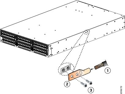
The chassis has a grounding pad with two threaded M4 holes for attaching a grounding lug. Figure 2-15 shows the system ground location on the Cisco Nexus 5020 switch. It is identical for the Cisco Nexus 5010 switch.
Warning When installing or replacing the unit, the ground connection must always be made first and disconnected last. Statement 1046
Caution All power supplies must be grounded. The receptacles of the AC power cables used to provide power to the chassis must be the grounding type, and the grounding conductors should connect to protective earth ground at the service equipment.
Figure 2-15 Grounding a Cisco Nexus 5000 Series Switch (Cisco Nexus 5020 Switch Shown)

Warning When installing or replacing the unit, the ground connection must always be made first and disconnected last.
Statement 1046
Caution Grounding the chassis is required if you are using DC power supplies, even if the rack is already grounded. A grounding pad with two threaded M4 holes is provided on the chassis for attaching a grounding lug. The ground lug must be NRTL listed. In addition, the copper conductor (wires) must be used and the copper conductor must comply with NEC code for ampacity.
To attach the grounding lug and cable to the chassis, follow these steps:
Step 1 Use a wire-stripping tool to remove approximately 0.75 inches (19 mm) of the covering from the end of the grounding cable.
Step 2 Insert the stripped end of the grounding cable into the open end of the grounding lug.
Step 3 Use the crimping tool to secure the grounding cable in the grounding lug.
Step 4 Remove the adhesive label from the grounding pad on the chassis.
Step 5 Place the grounding lug against the grounding pad so that there is solid metal-to-metal contact, and insert the two M4 screws with washers through the holes in the grounding lug and into the grounding pad.
Step 6 Ensure that the lug and cable do not interfere with other equipment.
Step 7 Prepare the other end of the grounding cable and connect it to an appropriate grounding point in your site to ensure adequate earth ground.
Starting the Switch
This section provides instructions for powering up the Cisco Nexus 5500 Series switch or the Cisco Nexus 5000 Series switch and verifying the component installation.
Note Do not connect the Ethernet port to the LAN until the initial switch configuration has been performed. For instructions on configuring the switch, see the Cisco Nexus 5000 Series CLI Configuration Guide. For instructions on connecting to the console port, see the “Connecting to the Console Port” section.
Warning When installing or replacing the unit, the ground connection must always be made first and disconnected last.
Statement 1046
To power up the switch and verify hardware operation, follow these steps:
Step 1 Verify that empty power supply slots have filler panels installed, the faceplates of all modules are flush with the front of the chassis, and the captive screws of the power supplies, fan module, and all expansion modules are tight.
Step 2 Verify that the power supply and the fan modules are installed.
Note Depending on the outlet receptacle on your power distribution unit, you may need the optional jumper power cord to connect the switch to your outlet receptacle. See the “Jumper Power Cord” section.
Step 3 Ensure that the switch is adequately grounded as described in the “Grounding the Switch” section, and that the power cables are connected to outlets that have the required AC power voltages (see the “Power Specifications” section).
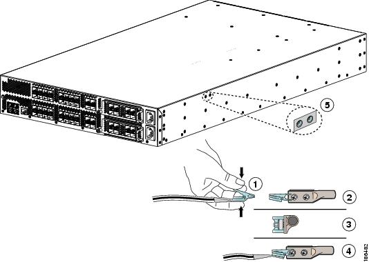
Step 4 For the Cisco Nexus 5020 switch and the Cisco Nexus 5010 switch, insert each end of the power clip (from the accessory kit) into holes on tabs located on either side of the power connectors (see Figure 2-16).
Figure 2-16 Attaching the Power Cord Clip to the Cisco Nexus 5010 Switch
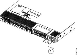
Step 5 Connect each power cable to the power connectors on the chassis and an AC power source. Press the power cable into the power clip to endure that the power cable stays connected to the chassis when bumped. The switch should power on as soon as you connect the power cable.
Step 6 Listen for the fans; they should begin operating when the power cable is plugged in.
Step 7 After the switch boots, verify that the LED operation is as follows:
- Fan module—Status LED is green.
- Power supply—Status LED is green.
- After initialization, the system status LED is green, indicating that all chassis environmental monitors are reporting that the system is operational. If this LED is orange or red, then one or more environmental monitor is reporting a problem.
- The Link LEDs for the Ethernet connector should not be on unless the cable is connected.
Note The link LEDs for the Fibre Channel ports remain yellow until the ports are enabled, and the LED for the Ethernet connector port remains off until the port is connected.
Step 8 Try removing and reinstalling a component that is not operating correctly. If it still does not operate correctly, contact your customer service representative for a replacement.
Note If you purchased this product through a Cisco reseller, contact the reseller directly for technical support. If you purchased this product directly from Cisco, contact Cisco Technical Support at this URL: http://www.cisco.com/c/en/us/support/web/tsd-cisco-worldwide-contacts.html.
Note Only one airflow direction is supported at a time in a Cisco Nexus 5000 Series switch. If a switch has modules for more than one airflow direction an error will occur with possible over heating and shutdown of the switch. If you power up the switch with modules using different airflow directions, you must shutdown the switch and replace the modules with the incorrect airflow direction before powering up the switch.
Step 9 Verify that the system software has booted and the switch has initialized without error messages.
If any problems occur, see Appendix E, “Troubleshooting Hardware Components.” If you cannot resolve an issue, contact your customer service representative.
Step 10 Complete the worksheets provided in Appendix G, “Site Planning and Maintenance Records” for future reference.
Note A setup utility automatically launches the first time you access the switch and guides you through the basic configuration. For instructions on how to configure the switch and check module connectivity, see the appropriate Cisco Nexus 5000 Series CLI configuration guide or the Cisco Nexus 5000 Series Fabric Manager Configuration Guide.
 Feedback