Feedback
Table Of Contents
General Requirements for Racks
Rack Requirements for Cisco MDS 9250i Chassis
Standard Open Rack Requirements
Requirements Specific to Two-Post Telco Rack
Before Installing the Rack-Mount Support Brackets
Installing and Removing the Brackets
Installing the Shelf Bracket Kit into a Four-Post EIA Rack
Installing the Switch on the Brackets
Installing the Switch on the Rack-Mount Support Brackets
Installing the Cisco MDS 9250i Switch in a Rack
Before Installing the Shelf Brackets
Installing the Cisco MDS 9250i Shelf Bracket Kit into a Rack
Installing the Switch on the Shelf Brackets
Rack Installation
This appendix provides information on the rack installation and includes the following sections:
•
Installing the Cisco MDS 9250i Switch in a Rack
Rack Requirements
This section provides the requirements for the following type of racks, assuming an external ambient air temperature range of 32 to 104oF (0 to 40oC):
•
•
•
General Requirements for Racks
The rack must be one of the following types:
•
•
Rack Requirements for Cisco MDS 9250i Chassis
The rack must also meet the following requirements:
•
•
Standard Open Rack Requirements
In addition to the requirements listed in the "General Requirements for Racks" section, if you are mounting the chassis in an open rack (no side panels or doors), ensure that the rack meets the following requirements:
•
•
Note
•
Requirements Specific to Two-Post Telco Rack
In addition to the requirements listed in the "General Requirements for Racks", two-post telco racks must meet the following requirements:
•
•
Rack-Mounting Guidelines
Caution
Caution
Before rack-mounting the chassis, ensure that the rack meets the following requirements:
•
•
•
•
•
Before Installing the Rack-Mount Support Brackets
Before installing the rack-mount support brackets for the Cisco MDS 9250i switch, check the contents of your kit. Table A-1 lists the contents of the optional shelf bracket kit.
Table A-1 Contents of Shelf Bracket Kit
2
Bottom support brackets
20
12-24 x 3/4-in. Phillips screws
20
M6 x 19 mm Phillips binder-head screws
Installing and Removing the Brackets
This section provides information on how to install and remove brackets.
Before installing the shelf brackets, check the contents of your kit. Table A-2 lists the contents of the optional shelf bracket kit.
Required Equipment
You need the following equipment for this installation:
•
•
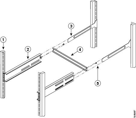
Installing the Shelf Bracket Kit into a Four-Post EIA Rack
Figure A-1 shows the installation of the shelf bracket kit into a four-post EIA rack.
Figure A-1 Installing the Shelf Bracket Kit into an EIA Rack
To install the shelf bracket in an EIA rack, follow these steps:
Step 1
Note
Step 2
Step 3
Step 4
Step 5
Installing the Switch on the Brackets
This section provides information on how to install the switch on the rack-mount support brackets and on the shelf brackets and includes the following subsections:
•
•
Installing the Switch on the Rack-Mount Support Brackets
This section provides general instructions for installing the switch on top of the rack-mount support brackets. For detailed installation instructions, see the "Installing the Cisco MDS 9250i Switch Chassis in a Rack" section.
Warning
Note
To install the switch on top of the rack-mount support brackets, follow these steps:
Step 1
Step 2
Step 3
Caution
Installing the Cisco MDS 9250i Switch in a Rack
This section describes the procedure for installing a Cisco MDS 9250i switch in a nonthreaded rack. It includes the following information:
•
•
•
Rack-Mounting Guidelines
Caution
Before rack-mounting the chassis, ensure that the rack meets the following requirements:
•
•
•
•
•
Before Installing the Shelf Brackets
Before installing the shelf brackets, check the contents of your kit. Table A-3 lists the contents of the optional shelf bracket kit.
Required Equipment
You need the following equipment for this installation:
•
•
Installing the Cisco MDS 9250i Shelf Bracket Kit into a Rack
Figure A-2 shows the installation of the Cisco MDS 9250i Shelf Bracket Kit into a four-post rack.
Figure A-2 Installing the Shelf Bracket Kit into a Rack
To install the shelf brackets in a rack, follow these steps:
Step 1
Note
Step 2
Step 3
Step 4
Installing the Switch on the Shelf Brackets
This section provides general instructions for installing the Cisco MDS 9250i switch on top of the shelf brackets. For detailed installation instructions, see "Installing the Cisco MDS 9250i Switch Chassis in a Rack" section.
Warning
Caution
Note
To install the Cisco MDS 9250i switch on top of the shelf brackets, follow these steps:
Step 1
Step 2
Step 3
Caution