Feedback
Table Of Contents
Cisco MDS 9250i Multiservice Fabric Switch Overview
Cisco MDS 9250i Integrated Supervisor Module
Fibre Channel SFP+ Transceivers
Cisco MDS 9250i Multiservice Fabric Switch Overview
This chapter describes the Cisco MDS 9250i Multiservice Fabric Switch and includes these topics:
•
Cisco MDS 9250i Integrated Supervisor Module
Introduction
The Cisco MDS 9250i Multiservice Fabric Switch (DS-C9250I-K9) is an optimized platform for deploying high-performance SAN extension solutions, distributed intelligent fabric services, and cost-effective multiprotocol connectivity for both open systems and mainframe environments.
The Cisco MDS 9250i switch is an ideal solution for local office and remote branch-office SANs and also in large-scale SANs operating the Cisco MDS 9700 and 9500 Series Multilayer director platforms.
The Cisco MDS 9250i switch offers 40 autosensing 2-, 4-, 8-, and 16-Gbps line-rate Fibre Channel ports, eight 10-Gigabit Ethernet Fibre Channel over Ethernet (FCoE) ports, and two 10-Gigabit Ethernet IP storage services ports in a fixed two-rack-unit (2RU) form factor.
The Cisco MDS 9250i switch can be deployed in the existing native Fibre Channel networks, which ensures protection of your investments in storage networks. Two 1- and 10-gigabit ports support Small Computer System Interface over IP (iSCSI) storage services. By using the eight 10 Gigabit Ethernet FCoE ports, the Cisco MDS 9250i switch can be attached to the directly connected FCoE and Fibre Channel storage devices. The Cisco MDS 9250i switch supports multi-tiered unified network fabric connectivity directly over FCoE. The Cisco MDS 9250i switch has front-to-back airflow and comes with a set of storage services for Fibre Channel and FCoE SANs with FCIP, IO accelerator (IOA), and data mobility migration (DMM).
The Cisco SAN Extension over IP application package license is enabled as standard on the two fixed 1/10 Gigabit Ethernet IP storage services ports, enabling features such as Fibre Channel over IP (FCIP) and compression on the switch without additional licenses.
The Cisco MDS 9250i switch is shipped with the following:
•
•
•
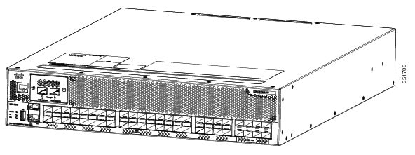
Figure 1-1 Cisco MDS 9250i Switch Front View
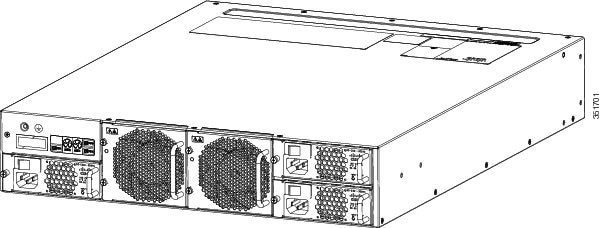
Figure 1-2
Cisco MDS 9250i Switch Rear View
Chassis Description
The Cisco MDS 9250i switch has a nonremovable supervisor module with 40 integrated 16-Gbps FC ports and eight 10-Gigabit Ethernet Fibre Channel over Ethernet (FCoE) ports.
The Cisco MDS 9250i switch also has these additional modules:
•
•
•
•
•
Cisco MDS 9250i Integrated Supervisor Module
The nonremovable Cisco MDS 9250i integrated supervisor module provides the control and management functions of the Cisco MDS 9250i Multiservice Fabric switch, and it includes 40 integrated 16-Gbps Fibre Channel switching ports and eight 10-Gigabit Ethernet Fibre Channel over Ethernet (FCoE) port modules.
The Cisco MDS 9250i integrated supervisor module has a PowerPC 8572E processor. It also has an internal CompactFlash card that provides 4 GB of storage for software images. The NVRAM consists of a battery, a battery controller and 512 Kx16 SRAM. SRAM used to store event logs, core dumps that are required to be stored after a power cycles.
Front Panel LEDs
The front panel of the Cisco MDS 9250i switch has the following LEDs:
•
•
•
Figure 1-3
Cisco MDS 9250i Ports and LEDs
CONSOLE Debug Port
USB Port
10G iSCSI/FC Ports
STATUS LED
FCoE Ports
P/S LED
Fibre Channel Ports
FAN LED
MGMT ETH Port
CONSOLE Port
The LEDs on the supervisor module indicate the status of the supervisor module, power supplies, and the system as a whole. Table 1-1 describes the LEDs.
Fan Modules
The Cisco MDS 9250i switch has two fan trays that are installed vertically at the back of the chassis. Each fan module can be removed while the other fan module continues to move air through the chassis.
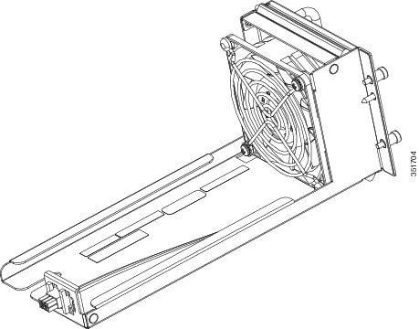
Figure 1-4
Cisco MDS 9250i Fan Module
One fan can fail without affecting the thermal performance of the system. Redundant fan controllers and other internal mechanisms are in place to ensure that any single fan tray does not go down.
If any single fan fails, the system continues to operate under all conditions. Two fan failures might cause alarms from ASIC when the temperature exceeds the threshold. At 104°F (40°C) or less, a single fan tray can be removed and the system can continue to operate long enough to allow for replacement of a failed fabric module or fan tray.
Power Supplies
The Cisco MDS 9250i Multiservice Fabric switch supports the following types of power supplies:
•
•
The Cisco MDS 9250i Multiservice Fabric switch supports up to three hot-swappable 300-W AC power supplies (AC input) (DS-C50I-300AC).
When connected to 220 VAC, the 300-W AC power supplies (DS-C50I-300AC) for the Cisco MDS 9250i switch provide an output power of 300 W to power the modules and fans. When connected to a 110 VAC power system, the power supply provides approximately 300 W. In this case, and if the power supplies are used in redundant rather than combined mode, they might not provide adequate power, depending on the number of modules loaded in the chassis.
Figure 1-5 Cisco MDS 9250i Switch 300-W AC Power Supply
Each power supply module monitors its output voltage and provides the status to the supervisor. The power supply modules also provide information about local fans, power, shutdown control, and E2PROM to the supervisor.
Supported Transceivers
The Cisco MDS 9250i switch supports these transceivers: 1000BASE-T, RJ-45, 8-Gbps SW/LW, LC Enhanced Small Form-Factor Pluggable (SFP+), 10-Gbps SW/LW, LC SFP+, 10-GbE SR/LR/ER, LC, SFP+, and 16-Gbps SW/LW LC SFP+.
Fibre Channel SFP+ Transceivers
The Fibre Channel SFP+ transceivers are field-replaceable and hot-swappable. You can use any combination of SFP+ transceivers that are supported by the switch. The only restrictions are that SWL transceivers must be paired with SWL transceivers, and LWL transceivers must be paired with LWL transceivers, and the cable must not exceed the stipulated cable length for reliable communications.
For more information about a specific Cisco SFP+ transceiver, see the "SFP+ Transceiver Specifications" section. SFP+ transceivers can be ordered separately or with the Cisco MDS 9250i switch.
Note