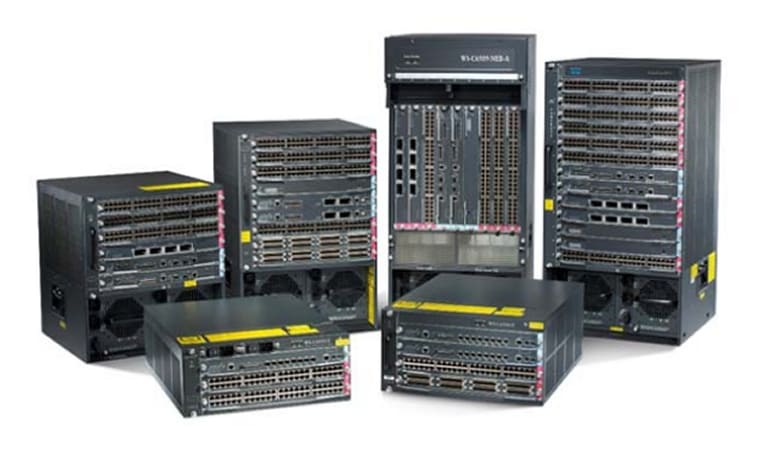
Table Of Contents
Configuring Failover
Understanding Failover
Failover System Requirements
Software Requirements
License Requirements
Failover and State Links
Failover Link
State Link
Intra- and Inter-Chassis Module Placement
Intra-Chassis Failover
Inter-Chassis Failover
Transparent Firewall Requirements
Active/Standby and Active/Active Failover
Active/Standby Failover
Active/Active Failover
Determining Which Type of Failover to Use
Regular and Stateful Failover
Regular Failover
Stateful Failover
Failover Health Monitoring
Unit Health Monitoring
Interface Monitoring
Configuring Failover
Using Active/Standby Failover
Prerequisites
Configuring Active/Standby Failover
Configuring Optional Active/Standby Failover Settings
Using Active/Active Failover
Prerequisites
Configuring Active/Active Failover
Configuring Optional Active/Active Failover Settings
Configuring Failover Communication Authentication/Encryption
Verifying the Failover Configuration
Viewing Failover Status
Viewing Monitored Interfaces
Viewing the Failover Configuration
Testing the Failover Functionality
Controlling and Monitoring Failover
Forcing Failover
Disabling Failover
Disabling Configuration Synchronization
Restoring a Failed Unit or Failover Group
Monitoring Failover
Failover System Messages
Debug Messages
SNMP
Configuring Failover
This chapter describes FWSM failover feature, which lets you configure two FWSMs so that one will take over operation if the other one fails. Failover is compatible with both routed and transparent firewall modes, and with single and multiple context modes.
This chapter includes the following sections:
•
Understanding Failover
•
Configuring Failover
•
Controlling and Monitoring Failover
For sample failover configurations, see the "Failover Example Configurations" section on page B-18.
Understanding Failover
The failover configuration requires two identical FWSMs connected to each other through a dedicated failover link and, optionally, a state link. The health of the active interfaces and units is monitored to determine if specific failover conditions are met. If those conditions are met, failover occurs.
FWSM supports two failover configurations, Active/Active failover and Active/Standby failover. Each failover configuration has its own method for determining and performing failover.
With Active/Active failover, both units can pass network traffic. This lets you configure load balancing on your network. Active/Active failover is only available on units running in multiple context mode.
With Active/Standby failover, only one unit passes traffic while the other unit waits in a standby state. Active/Standby failover is available on units running in either single or multiple context mode.
Both failover configurations support stateful or stateless (regular) failover.
This section includes the following topics:
•
Failover System Requirements
•
Failover and State Links
•
Intra- and Inter-Chassis Module Placement
•
Transparent Firewall Requirements
•
Active/Standby and Active/Active Failover
•
Regular and Stateful Failover
•
Failover Health Monitoring
Failover System Requirements
This section describes the software and license requirements for FWSMs in a failover configuration. This section contains the following topics:
•
Software Requirements
•
License Requirements
Software Requirements
The two units in a failover configuration must have the same major (first number) and minor (second number) software version. However, you can use different versions of the software during an upgrade process; for example, you can upgrade one unit from Version 3.1(1) to Version 3.1(2) and have failover remain active. We recommend upgrading both units to the same version to ensure long-term compatibility.
License Requirements
Both units must have the same license.
Failover and State Links
This section describes the failover and the state links, which are dedicated connections between the two units in a failover configuration. This section includes the following topics:
•
Failover Link
•
State Link
Failover Link
The two units in a failover pair constantly communicate over a failover link to determine the operating status of each unit. The following information is communicated over the failover link:
•
The unit state (active or standby).
•
Hello messages (keep-alives).
•
Network link status.
•
MAC address exchange.
•
Configuration replication and synchronization.
Caution 
All information sent over the failover and Stateful Failover links is sent in clear text unless you secure the communication with a failover key.
The failover link uses a special VLAN interface that you do not configure as a normal networking interface; rather, it exists only for failover communications. This VLAN should only be used for the failover link (and optionally for the state link). Sharing the failover link VLAN with any other VLANs can cause intermittent traffic problems and ping and ARP failures. For inter-chassis failover, use dedicated interfaces on the switch for the failover link.
Note
If failover and the interface are configured but the VLAN is not downloaded from the switch and the failover is in disabled mode, then the FWSM doesn't send ARP requests by design because it could confilct with another FWSM currently running as Active in the system.
On systems running in multiple context mode, the failover link resides in the system context. This interface and the state link, if used, are the only interfaces that you can configure in the system context. All other interfaces are allocated to and configured from within security contexts.
Note
The IP address and MAC address for the failover link do not change at failover.
State Link
To use Stateful Failover, you must configure a state link to pass all state information. This link can be the same as the failover link, but we recommend that you assign a separate VLAN and IP address for the state link. The state traffic can be large, and performance is improved with separate links.
The state link interface is not configured as a normal networking interface; it exists only for Stateful Failover communications and, optionally, for the failover communication if you share the state and failover links.
In multiple context mode, the state link resides in the system context. This interface and the failover interface are the only interfaces in the system context. All other interfaces are allocated to and configured from within security contexts.
Note
The IP address and MAC address for the state link do not change at failover.
Caution 
All information sent over the failover and Stateful Failover links is sent in clear text unless you secure the communication with a failover key.
Intra- and Inter-Chassis Module Placement
You can place the primary and secondary FWSMs within the same switch or in two separate switches. The following sections describe each option:
•
Intra-Chassis Failover
•
Inter-Chassis Failover
Intra-Chassis Failover
If you install the secondary FWSM in the same switch as the primary FWSM, you protect against module-level failure. To protect against switch-level failure, as well as module-level failure, see the "Inter-Chassis Failover" section.
Even though both FWSMs are assigned the same VLANs, only the active module takes part in networking. The standby module does not pass any traffic.
Figure 13-1 shows a typical intra-switch configuration.
Figure 13-1 Intra-Switch Failover
Inter-Chassis Failover
To protect against switch-level failure, you can install the secondary FWSM in a separate switch. FWSM does not coordinate failover directly with the switch, but it works harmoniously with the switch failover operation. See the switch documentation to configure failover for the switch.
To accommodate the failover communications between FWSMs, we recommend that you configure a trunk port between the two switches that carries the failover and state VLANs. The trunk ensures that failover communication between the two units is subject to minimal failure risk.
For other VLANs, you must ensure that both switches have access to all firewall VLANs, and that monitored VLANs can successfully pass hello packets between both switches.
Figure 13-2 shows a typical switch and FWSM redundancy configuration. The trunk between the two switches carries the failover FWSM VLANs (VLANs 10 and 11).
Note
FWSM failover is independent of the switch failover operation; however, FWSM works in any switch failover scenario.
Figure 13-2 Normal Operation
If the primary FWSM fails, then the secondary FWSM becomes active and successfully passes the firewall VLANs (Figure 13-3).
Figure 13-3 FWSM Failure
If the entire switch fails, as well as the FWSM (such as in a power failure), then both the switch and the FWSM fail over to their secondary units (Figure 13-4).
Figure 13-4 Switch Failure
Transparent Firewall Requirements
To avoid loops when you use failover in transparent mode, you must use switch software that supports BPDU forwarding, and you must configure the FWSM to allow BPDUs. See the "Switch Hardware and Software Compatibility" section on page A-1 for switch software versions that allow BPDUs automatically.
To allow BPDUs through the FWSM, configure an EtherType ACL and apply it to both interfaces according to the "Adding an EtherType Access List" section on page 10-8.
Loops can occur if both modules are active at the same time, such as when both modules are discovering the presence of the other module, or due to a bad failover link. Because the FWSMs bridge packets between the same two VLANs, loops can occur when inside packets destined for the outside get endlessly replicated by both FWSMs (see Figure 13-5). The spanning tree protocol can break such loops if there is a timely exchange of BPDUs. To break the loop, BPDUs sent between VLAN 200 and VLAN 201 need to be bridged.
Figure 13-5 Potential Loops in Transparent Mode
Active/Standby and Active/Active Failover
This section describes each failover configuration in detail. This section includes the following topics:
•
Active/Standby Failover
•
Active/Active Failover
•
Determining Which Type of Failover to Use
Active/Standby Failover
This section describes Active/Standby failover and includes the following topics:
•
Active/Standby Failover Overview
•
Primary/Secondary Status and Active/Standby Status
•
Device Initialization and Configuration Synchronization
•
Command Replication
•
Failover Triggers
•
Failover Actions
Active/Standby Failover Overview
Active/Standby failover lets you use a standby FWSM to take over the functionality of a failed unit. When the active unit fails, it changes to the standby state while the standby unit changes to the active state. The unit that becomes active assumes the IP addresses (or, for transparent firewall, the management IP address) and the MAC address of the failed unit and begins passing traffic. The unit that is now in standby state takes over the standby IP addresses and MAC address. Because network devices see no change in the MAC to IP address pairing, no ARP entries change or time out anywhere on the network.
Note
For multiple context mode, FWSM can fail over the entire unit (including all contexts) but cannot fail over individual contexts separately.
Primary/Secondary Status and Active/Standby Status
The main difference between the two units in a failover pair are related to which unit is active and which unit is standby, namely which IP addresses to use and which unit actively passes traffic.
However, a few differences exist between the units based on which unit is primary (as specified in the configuration) and which unit is secondary:
•
The primary unit always becomes the active unit if both units start up at the same time (and are of equal operational health).
•
The primary unit MAC address is always coupled with the active IP addresses. The exception to this rule occurs when the secondary unit is active, and cannot obtain the primary MAC address over the failover link. In this case, the secondary MAC address is used.
Device Initialization and Configuration Synchronization
Configuration synchronization occurs when one or both devices in the failover pair boot. Configurations are always synchronized from the active unit to the standby unit. When the standby unit completes its initial startup, it clears its running configuration (except for the failover commands needed to communicate with the active unit), and the active unit sends its entire configuration to the standby unit.
The active unit is determined by the following:
•
If a unit boots and detects a peer already running as active, it becomes the standby unit.
•
If a unit boots and does not detect a peer, it becomes the active unit.
•
If both units boot simultaneously, then the primary unit becomes the active unit and the secondary unit becomes the standby unit.
Note
If the secondary unit boots without detecting the primary unit, it becomes the active unit. It uses its own MAC address for the active IP addresses. However, when the primary unit becomes available, the secondary unit changes the MAC address to that of the primary unit, which can cause an interruption in your network traffic.
When the configuration synchronization starts, the FWSM console on the active unit displays the message "Beginning configuration replication: Sending to mate," and when it is complete, the FWSM console displays the message "End Configuration Replication to mate." During the configuration synchronization, commands entered on the active unit may not replicate properly to the standby unit, and commands entered on the standby unit may be overwritten by the configuration being replicated from the active unit. Avoid entering commands on either unit in the failover pair during the configuration replication process. Depending upon the size of the configuration, replication can take from a few seconds to several minutes.
If you enter the write standby command on the active unit, the standby unit clears its running configuration (except for the failover commands used to communicate with the active unit), and the active unit sends its entire configuration to the standby unit.
In multiple context mode, when you enter the write standby command in the system execution space, all contexts are replicated. If you enter the write standby command within a context, the command replicates only the context configuration.
On the standby unit, the replicated configuration exists only in running memory. To save the configuration to Flash memory after synchronization:
•
In single context mode, enter the write memory command on the active unit. The command is replicated to the standby unit, which proceeds to write its configuration to Flash memory.
•
In multiple context mode, enter the write memory all command on the active unit from the system execution space. This command saves the system configuration and all context configurations. The command is replicated to the standby unit, which proceeds to write its configurations to Flash memory. Contexts with startup configurations on external servers are accessible from either unit over the network and do not need to be saved separately for each unit. Alternatively, you can copy the contexts on disk from the active unit to an external server, and then copy them to disk on the standby unit, where they become available when the unit reloads.
Command Replication
As commands are entered on the active unit, they are sent across the failover link to the standby unit. Command replication always flows from the active unit to the standby unit. Replicated commands are stored in the running configuration of the standby unit. Saving the running configuration to the startup configuration on the active unit causes the running configuration to be saved to the startup configuration on the standby unit; however, you do not have to save the active configuration to Flash memory to replicate the commands.
Note
The RSA keys are not synchronized from the primary to the secondary unit in FWSM.
Note
The mode command is not replicated to the secondary unit.
Changes made on the standby unit are not replicated to the active unit. If you enter a command on the standby unit, FWSM displays the message **** WARNING **** Configuration Replication is NOT performed from Standby unit to Active unit. Configurations are no longer synchronized. This message displays even when you enter many commands that do not affect the configuration.
Failover Triggers
The unit can fail if one of the following events occurs:
•
The unit has a hardware failure or a power failure.
•
The unit has a software failure.
•
Too many monitored interfaces fail.
•
The no failover active command is entered on the active unit or the failover active command is entered on the standby unit.
Failover Actions
In Active/Standby failover, failover occurs on a unit basis. Even on systems running in multiple context mode you cannot fail over individual or groups of contexts with Active/Standby failover.
Table 13-1 shows the failover action for each failure event. For each failure event, the table shows the failover policy (failover or no failover), the action taken by the active unit, the action taken by the standby unit, and any special notes about the failover condition and actions.
Table 13-1 Failover Behavior
Failure Event
|
Policy
|
Active Action
|
Standby Action
|
Notes
|
Active unit failed (power or hardware)
|
Failover
|
n/a
|
Become active
Mark active as failed
|
No hello messages are received on any monitored interface or the failover link.
|
Formerly active unit recovers
|
No failover
|
Become standby
|
No action
|
None.
|
Standby unit failed (power or hardware)
|
No failover
|
Mark standby as failed
|
n/a
|
When the standby unit is marked as failed, then the active unit will not attempt to fail over, even if the interface failure threshold is surpassed.
|
Failover link failed during operation
|
No failover
|
Mark failover interface as failed
|
Mark failover interface as failed
|
You should restore the failover link as soon as possible because the unit cannot fail over to the standby unit while the failover link is down.
|
Failover link failed at startup
|
No failover
|
Mark failover interface as failed
|
Become active
|
If the failover link is down at startup, both units will become active.
|
State link failed
|
No failover
|
No action
|
No action
|
State information will become out of date, and sessions will be terminated if a failover occurs.
|
Interface failure on active unit above threshold
|
Failover
|
Mark active as failed
|
Become active
|
None.
|
Interface failure on standby unit above threshold
|
No failover
|
No action
|
Mark standby as failed
|
When the standby unit is marked as failed, then the active unit will not attempt to fail over even if the interface failure threshold is surpassed.
|
Active/Active Failover
This section describes Active/Active failover. This section includes the following topics:
•
Active/Active Failover Overview
•
Primary/Secondary Status and Active/Standby Status
•
Device Initialization and Configuration Synchronization
•
Command Replication
•
Failover Triggers
•
Failover Actions
Active/Active Failover Overview
Active/Active failover is only available to FWSMs in multiple context mode. In an Active/Active failover configuration, both FWSMs can pass network traffic.
In Active/Active failover, you divide the security contexts on FWSM into failover groups. A failover group is simply a logical group of one or more security contexts. You can create a maximum of two failover groups on FWSM. The admin context is always a member of failover group 1, and any unassigned security contexts are also members of failover group 1 by default.
The failover group forms the base unit for failover in Active/Active failover. Interface failure monitoring, failover, and active/standby status are all attributes of a failover group rather than of the unit. The MAC address of the primary unit is used by all interfaces in the active contexts.
When an active failover group fails, it changes to the standby state while the associated standby failover group becomes active. The interfaces in the failover group that becomes active assume the MAC address and IP addresses of the interfaces in the failover group that failed. The interfaces in the failover group that is now in the standby state take over the standby MAC address and IP addresses.
Note
A failover group failing on a unit does not mean that the unit has failed. The unit may still have another failover group passing traffic on it.
When creating the failover groups, you should create them on the unit that will have failover group 1 in the active state.
Primary/Secondary Status and Active/Standby Status
As in Active/Standby failover, one unit in an Active/Active failover pair is designated the primary unit, and the other unit the secondary unit. Unlike Active/Standby failover, this designation does not indicate which unit becomes active when both units start simultaneously. Instead, the primary/secondary designation determines which unit provides the running configuration to the pair and on which unit each failover group appears in the active state when both units start simultaneously.
Each failover group in the configuration is given a primary or secondary unit preference. This preference determines on which unit in the failover pair the contexts in the failover group appear in the active state when both units start simultaneously. You can have both failover groups be in the active state on a single unit in the pair, with the other unit containing the failover groups in the standby state. However, a more typical configuration is to assign each failover group a different role preference to make each one active on a different unit, balancing the traffic across the devices.
Note
FWSM does not provide load balancing services. Load balancing must be handled by a router passing traffic to FWSM.
Device Initialization and Configuration Synchronization
Configuration synchronization occurs when one or both units in a failover pair boot.
When a unit boots while the peer unit is not available, then both failover groups become active on the unit regardless of the primary or secondary designation for the failover groups and the unit. Configuration synchronization does not occur. Some reasons a peer unit may not be available are that the peer unit is powered down, the peer unit is in a failed state, or the failover link between the units has not been established.
When a unit boots while the peer unit is active (with both failover groups active on it), the booting unit contacts the active unit to obtain the running configuration. By default, the failover groups will remain active on the active unit regardless of the primary or secondary preference of each failover group and unit designation (unless configured with the preempt command). The failover groups remain active on the first unit until one of the following occurs:
•
A failover condition causes the failover group to become active on the peer unit.
•
You manually force a failover group to become active on the peer unit using the no failover active command.
•
The preempt command forces the failover group to become active on its preferred unit when that unit becomes available.
When both units boot at the same time, the primary unit becomes the active unit. The secondary unit obtains the running configuration from the primary unit. Once the configuration has been synchronized, each failover group becomes active on its preferred unit.
Command Replication
After both units are running, commands are replicated from one unit to the other as follows:
•
Commands entered within a security context are replicated from the unit on which the security context appears in the active state to the peer unit.
Note
A context is considered in the active state on a unit if the failover group to which it belongs is in the active state on that unit.
•
Commands entered in the system execution space are replicated from the unit on which failover group 1 is in the active state to the unit on which failover group 1 is in the standby state.
•
Commands entered in the admin context are replicated from the unit on which failover group 1 is in the active state to the unit on which failover group 1 is in the standby state.
Failure to enter the commands on the appropriate unit for command replication to occur will cause the configurations to become out of synchronization. Those changes may be lost the next time configuration synchronization occurs.
Note
The mode command does not get replicated.
You can use the write standby command to resynchronize configurations that have become out of sync. For Active/Active failover, the write standby command behaves as follows:
•
If you enter the write standby command in the system execution space, the system configuration and the configurations for all of the security contexts on FWSM is written to the peer unit. This includes configuration information for security contexts that are in the standby state. You must enter the command in the system execution space on the unit that has failover group 1 in the active state.
•
If you enter the write standby command in a security context, only the configuration for the security context is written to the peer unit. You must enter the command in the security context on the unit where the security context appears in the active state.
Replicated commands are not saved to the Flash memory when replicated to the peer unit. They are added to the running configuration. To save replicated commands to Flash memory on both units, use the write memory or copy running-config startup-config command on the unit that you made the changes on. The command will be replicated to the peer unit and cause the configuration to be saved to Flash memory on the peer unit.
Failover Triggers
In Active/Active failover, failover can be triggered at the unit level if one of the following events occurs:
•
The unit has a hardware failure.
•
The unit has a power failure.
•
The unit has a software failure.
•
The no failover active or the failover active command is entered in the system execution space.
Failover is triggered at the failover group level when one of the following events occurs:
•
Too many monitored interfaces in the contexts that belong to the failover group fail.
•
The no failover active group group_id command is entered.
You configure the failover threshold for each failover group by specifying the number or percentage of interfaces within the failover group that must fail before the group fails. Because a failover group can contain multiple contexts, and each context can contain multiple interfaces, it is possible for all interfaces in a single context to fail without causing the associated failover group to fail.
See the "Failover Health Monitoring" section for more information about interface and unit monitoring.
Failover Actions
In an Active/Active failover configuration, failover occurs on a failover group basis, not a system basis. For example, if you designate both failover groups as active on the primary unit, and failover group 1 fails, then failover group 2 remains active on the primary unit while failover group 1 becomes active on the secondary unit.
Note
When configuring Active/Active failover, make sure that the combined traffic for both units is within the capacity of each unit.
Table 13-2 shows the failover action for each failure event. For each failure event, the policy (whether or not failover occurs), actions for the active failover group, and actions for the standby failover group are given.
Table 13-2 Failover Behavior for Active/Active Failover
Failure Event
|
Policy
|
Active Group Action
|
Standby Group Action
|
Notes
|
A unit experiences a power or software failure
|
Failover
|
Become standby Mark as failed
|
Become active
Mark active as failed
|
When a unit in a failover pair fails, any active failover groups on that unit are marked as failed and become active on the peer unit.
|
Interface failure on active failover group above threshold
|
Failover
|
Mark active group as failed
|
Become active
|
None.
|
Interface failure on standby failover group above threshold
|
No failover
|
No action
|
Mark standby group as failed
|
When the standby failover group is marked as failed, then the active failover group will not attempt to fail over, even if the interface failure threshold is surpassed.
|
Formerly active failover group recovers
|
No failover
|
No action
|
No action
|
Unless configured with the preempt command, the failover groups remain active on their current unit.
|
Failover link failed at startup
|
No failover
|
Become active
|
Become active
|
If the failover link is down at startup, both failover groups on both units will become active.
|
State link failed
|
No failover
|
No action
|
No action
|
State information will become out of date, and sessions will be terminated if a failover occurs.
|
Failover link failed during operation
|
No failover
|
n/a
|
n/a
|
Each unit marks the failover interface as failed. You should restore the failover link as soon as possible because the unit cannot fail over to the standby unit while the failover link is down.
|
Determining Which Type of Failover to Use
The type of failover you choose depends upon your FWSM configuration and how you plan to use FWSM.
If you are running FWSM in single mode, then you can only use Active/Standby failover; Active/Active failover is only available to FWSMs running in multiple context mode. If you are running the FWSM in multiple context mode, then you can configure either Active/Active failover or Active/Standby failover.
If you are using an upstream router to provide load balancing, use Active/Active failover. If you do not want to provide load balancing, use either Active/Standby or Active/Active failover.
Table 13-3 provides a comparison of some of the features supported by each type of failover configuration.
Table 13-3 Failover Configuration Feature Support
Feature
|
Active/Active
|
Active/Standby
|
Single Context Mode
|
No
|
Yes
|
Multiple Context Mode
|
Yes
|
Yes
|
Load Balancing Network Configurations
|
Yes
|
No
|
Unit Failover
|
Yes
|
Yes
|
Failover of Groups of Contexts
|
Yes
|
No
|
Failover of Individual Contexts
|
No
|
No
|
Regular and Stateful Failover
FWSM supports two types of failover, regular and stateful. This section includes the following topics:
•
Regular Failover
•
Stateful Failover
Regular Failover
When a failover occurs, all active connections are dropped. Clients need to reestablish connections when the new active unit takes over.
Stateful Failover
When Stateful Failover is enabled, the active unit continually passes per-connection state information to the standby unit. After a failover occurs, the same connection information is available at the new active unit. Supported end-user applications are not required to reconnect to keep the same communication session.
The state information passed to the standby unit includes the following:
•
NAT translation table.
•
TCP connection states.
•
UDP connection states.
•
The ARP table.
•
The Layer 2 bridge table (when running in transparent firewall mode).
•
The HTTP connection states (if HTTP replication is enabled).
•
The ISAKMP and IPSec SA table.
•
GTP PDP connection database.
The information that is not passed to the standby unit when Stateful Failover is enabled includes the following:
•
The HTTP connection table (unless HTTP replication is enabled).
•
The user authentication (uauth) table.
•
The routing tables.
•
Multicast traffic information.
Note
If failover occurs during an active Cisco IP SoftPhone session, the call will remain active because the call session state information is replicated to the standby unit. When the call is terminated, the IP SoftPhone client will lose connection with the CallManager. This occurs because there is no session information for the CTIQBE hangup message on the standby unit. When the IP SoftPhone client does not receive a response back from the CallManager within a certain time period, it considers the CallManager unreachable and unregisters itself.
Failover Health Monitoring
FWSM monitors each unit for overall health and for interface health. See the following sections for more information about how FWSM performs tests to determine the state of each unit:
•
Unit Health Monitoring
•
Interface Monitoring
Unit Health Monitoring
FWSM determines the health of the other unit by monitoring the failover link. When a unit does not receive hello messages on the failover link, then the unit sends an ARP request on all interfaces, including the failover interface. FWSM retries a user-configurable number of times. The action FWSM takes depends on the response from the other unit. See the following possible actions:
•
If FWSM receives a response on any interface, then it does not fail over.
•
If FWSM does not receive a response on any interface, then the standby unit switches to active mode and classifies the other unit as failed.
•
If FWSM does not receive a response on the failover link only, then the unit does not failover. The failover link is marked as failed. You should restore the failover link as soon as possible because the unit cannot fail over to the standby while the failover link is down.
Note
If a failed unit does not recover and you believe it should not be failed, you can reset the state by entering the failover reset command. If the failover condition persists, however, the unit will fail again.
Interface Monitoring
You can monitor up to 250 interfaces divided between all contexts. You can configure one context to monitor a shared interface (because the interface is shared, all contexts benefit from the monitoring).
When a unit does not receive hello messages on a monitored interface, it runs the following tests:
1.
Link Up/Down test—A test of the interface status. If the Link Up/Down test indicates that the interface is operational, then FWSM performs network tests. The purpose of these tests is to generate network traffic to determine which (if either) unit has failed. At the start of each test, each unit clears its received packet count for its interfaces. At the conclusion of each test, each unit looks to see if it has received any traffic. If it has, the interface is considered operational. If one unit receives traffic for a test and the other unit does not, the unit that received no traffic is considered failed. If neither unit has received traffic, then the next test is used.
2.
Network Activity test—A received network activity test. The unit counts all received packets for up to 5 seconds. If any packets are received at any time during this interval, the interface is considered operational and testing stops. If no traffic is received, the ARP test begins.
3.
ARP test—A reading of the unit ARP cache for the 2 most recently acquired entries. One at a time, the unit sends ARP requests to these machines, attempting to stimulate network traffic. After each request, the unit counts all received traffic for up to 5 seconds. If traffic is received, the interface is considered operational. If no traffic is received, an ARP request is sent to the next machine. If at the end of the list no traffic has been received, the ping test begins.
4.
Broadcast Ping test—A ping test that consists of sending out a broadcast ping request. The unit then counts all received packets for up to 5 seconds. If any packets are received at any time during this interval, the interface is considered operational and testing stops.
If all network tests fail for an interface, but this interface on the other unit continues to successfully pass traffic, then the interface is considered to be failed. If the threshold for failed interfaces is met, then a failover occurs. If the other unit interface also fails all the network tests, then both interfaces go into the "Unknown" state and do not count towards the failover limit.
An interface becomes operational again if it receives any traffic. A failed FWSM returns to standby mode if the interface failure threshold is no longer met.
Note
If a failed unit does not recover and you believe it should not be failed, you can reset the state by entering the failover reset command. If the failover condition persists, however, the unit will fail again.
Configuring Failover
This section describes how to configure failover and includes the following topics:
•
Using Active/Standby Failover
•
Using Active/Active Failover
•
Configuring Failover Communication Authentication/Encryption
•
Verifying the Failover Configuration
Using Active/Standby Failover
This section provides step-by-step procedures for configuring Active/Standby failover. This section includes the following topics:
•
Prerequisites
•
Configuring Active/Standby Failover
•
Configuring Optional Active/Standby Failover Settings
See the "Failover Example Configurations" section on page B-18 for examples of typical failover configurations.
Prerequisites
Before you begin, verify the following:
•
Both units have the proper license.
•
If the primary unit is in single context mode, the secondary unit must also be in single context mode and also be in the same firewall mode as the primary unit.
•
If the primary unit is in multiple context mode, the secondary unit must also be in multiple context mode. You do not need configure the firewall mode of the security contexts on the secondary unit because the failover and state links reside in the system context. The secondary unit obtains the security context configuration from the primary unit.
Note
The mode command does not get replicated to the secondary unit.
Configuring Active/Standby Failover
This section describes how to configure Active/Standby failover. You must configure the secondary unit to recognize the failover link before the secondary unit can obtain the running configuration from the primary unit.
This section includes the following topics:
•
Configuring the Primary Unit
•
Configuring the Secondary Unit
Configuring the Primary Unit
Follow these steps to configure the primary unit in an Active/Standby failover configuration. These steps provide the minimum configuration needed to enable failover on the primary unit. For multiple context mode, all steps are performed in the system execution space unless otherwise noted.
To configure the primary unit in an Active/Standby failover pair, perform the following steps:
Step 1
If you have not done so already, configure the active and standby IP addresses for each interface (routed mode) or for the management address (transparent mode). The standby IP address is used on the FWSM that is currently the standby unit. It must be in the same subnet as the active IP address.
Note
Do not configure an IP address for the failover link or for the state link (if you are going to use Stateful Failover).
hostname(config-if)# ip address active_addr netmask standby standby_addr
Note
In multiple context mode, you must configure the interface addresses from within each context. Use the changeto context command to switch between contexts. The command prompt changes to hostname/context(config-if)#, where context is the name of the current context.
Step 2
Designate the unit as the primary unit:
hostname(config)# failover lan unit primary
Step 3
Define the failover interface.
a.
Specify the interface to be used as the failover interface:
hostname(config)# failover lan interface if_name vlan vlan
The if_name argument assigns a name to the interface specified by the vlan argument.
b.
Assign the active and standby IP address to the failover link:
hostname(config)# failover interface ip if_name ip_addr mask standby ip_addr
The standby IP address must be in the same subnet as the active IP address. You do not need to identify the standby address subnet mask.
The failover link IP address and MAC address do not change at failover. The active IP address for the failover link always stays with the primary unit, while the standby IP address stays with the secondary unit.
Step 4
(Optional) To enable Stateful Failover, configure the state link. The state link must be configured on an unused interface.
a.
Specify the interface to be used as state link:
hostname(config)# failover link if_name [vlan vlan]
Note
If the state link uses the failover link, then you only need to supply the if_name argument.
The if_name argument assigns a logical name to the interface specified by the vlan argument. This interface should not be used for any other purpose except, optionally, the failover link.
b.
Assign an active and standby IP address to the state link.
Note
If the state link uses the failover link, skip this step. You have already defined the failover link active and standby IP addresses.
hostname(config)# failover interface ip if_name ip_addr mask standby ip_addr
The standby IP address must be in the same subnet as the active IP address. You do not need to identify the standby address subnet mask.
The state link IP address and MAC address do not change at failover. The active IP address always stays with the primary unit, while the standby IP address stays with the secondary unit.
Step 5
To enable monitoring on an interface, enter the following command:
hostname(config)# monitor-interface interface_name
The maximum number of interfaces to monitor on the FWSM (divided between all contexts) is 250.
Note
In multiple context mode, you must configure interface monitoring from within each context. Use the changeto context command to switch between contexts. The command prompt changes to hostname/context(config)#, where context is the name of the current context.
Step 6
Enable failover:
hostname(config)# failover
Step 7
Save the configuration:
hostname(config)# write memory
Note
In multiple context mode, enter write memory all in the system execution space to save all context configurations.
Configuring the Secondary Unit
The only configuration required on the secondary unit is for the failover interface. The secondary unit requires these commands to initially communicate with the primary unit. After the primary unit sends its configuration to the secondary unit, the only permanent difference between the two configurations is the failover lan unit command, which identifies each unit as primary or secondary.
For multiple context mode, all steps are performed in the system execution space unless noted otherwise.
To configure the secondary unit, perform the following steps:
Step 1
Define the failover interface. Use the same settings as you used for the primary unit.
a.
Specify the interface to be used as the failover interface:
hostname(config)# failover lan interface if_name vlan vlan
The if_name argument assigns a name to the interface specified by the vlan argument.
b.
Assign the active and standby IP address to the failover link:
hostname(config)# failover interface ip if_name ip_addr mask standby ip_addr
Note
Enter this command exactly as you entered it on the primary unit when you configured the failover interface on the primary unit.
Step 2
(Optional) Designate this unit as the secondary unit:
hostname(config)# failover lan unit secondary
Note
This step is optional because by default units are designated as secondary unless previously configured.
Step 3
Enable failover:
hostname(config)# failover
After you enable failover, the active unit sends the configuration in running memory to the standby unit. As the configuration synchronizes, the messages "Beginning configuration replication: Sending to mate" and "End Configuration Replication to mate" appear on the active unit console.
Step 4
After the running configuration has completed replication, save the configuration to Flash memory:
hostname(config)# write memory
Configuring Optional Active/Standby Failover Settings
You can configure the following optional Active/Standby failover setting when you are initially configuring failover or after failover has already been configured. Unless otherwise noted, the commands should be entered on the active unit.
This section includes the following topics:
•
Enabling HTTP Replication with Stateful Failover
•
Configuring Interface and Unit Poll Times
•
Configuring Failover Criteria
Enabling HTTP Replication with Stateful Failover
To allow HTTP connections to be included in the state information replication, you need to enable HTTP replication. Because HTTP connections are typically short-lived, and because HTTP clients typically retry failed connection attempts, HTTP connections are not automatically included in the replicated state information.
Enter the following command in global configuration mode to enable HTTP state replication when Stateful Failover is enabled:
hostname(config)# failover replication http
Configuring Interface and Unit Poll Times
FWSM monitors both unit and interface health for failover. You can configure the amount of time between hello messages when monitoring interface and unit health. Decreasing the poll time allows an interface or unit failure to be detected more quickly, but consumes more system resources.
To change the interface poll time, enter the following command in global configuration mode:
hostname(config)# failover polltime interface seconds
To change the unit poll time, enter the following command in global configuration mode:
hostname(config)# failover polltime seconds
To change the unit hold time, enter the following command in global configuration mode:
hostname(config)# failover holdtime seconds
The defaults are as follows:
•
The interface poll time is 15 seconds.
•
The unit poll time is 1 second.
•
The holdtime time is 3 times the poll time (with a minimum value of 3 seconds) if you specify a poll time but do not specify a hold time with the holdtime keyword. If you specify a hold time using the holdtime keyword, it must be at least 3 times the poll time. If you enter the clear configure failover command, the hold time is 15 seconds.
Note
You cannot enter a holdtime value that is less than 3 times the unit poll time. With a faster poll time, the FWSM can detect failure and trigger failover faster. However, faster detection can cause unnecessary switchovers when the network is temporarily congested.
Configuring Failover Criteria
By default, failure of 50% of monitored interfaces causes failover. You can specify a specific number of interfaces or a percentage of monitored interfaces that must fail before a failover occurs.
To change the default failover criteria, enter the following command in global configuration mode:
hostname(config)# failover interface-policy num[%]
When specifying a specific number of interfaces, the num argument can be from 1 to 250. When specifying a percentage of interfaces, the num argument can be from 1 to 100.
Using Active/Active Failover
This section describes how to configure Active/Active failover.
This section includes the following topics:
•
Prerequisites
•
Configuring Active/Active Failover
•
Configuring Optional Active/Active Failover Settings
See the "Failover Example Configurations" section on page B-18 for examples of typical failover configurations.
Prerequisites
Before you begin, verify the following:
•
Both units have the proper license.
•
Both units are in multiple context mode. You do not need configure the firewall mode of the security contexts on the secondary unit because the failover and state links reside in the system context. The secondary unit obtains the security context configuration from the primary unit.
Note
The mode command does not get replicated to the secondary unit.
Configuring Active/Active Failover
This section describes how to configure Active/Active failover. You must configure the secondary unit to recognize the failover link before the secondary unit can obtain the running configuration from the primary unit.
This section includes the following topics:
•
Configure the Primary Unit
•
Configure the Secondary Unit
Configure the Primary Unit
To configure the primary unit in an Active/Active failover configuration, perform the following steps:
Step 1
Configure the basic failover parameters in the system execution space.
a.
Designate the unit as the primary unit:
hostname(config)# failover lan unit primary
b.
Specify the failover link:
hostname(config)# failover lan interface if_name vlan vlan
The if_name argument assigns a logical name to the interface specified by the vlan argument. This interface should not be used for any other purpose (except, optionally, the state link).
c.
Specify the failover link active and standby IP addresses:
hostname(config)# failover interface ip if_name ip_addr mask standby ip_addr
The standby IP address must be in the same subnet as the active IP address. You do not need to identify the standby IP address subnet mask. The failover link IP address does not change at failover. The active IP address always stays with the primary unit, while the standby IP address stays with the secondary unit.
Step 2
(Optional) To enable Stateful Failover, configure the state link. The state link must be configured on an unused interface.
a.
Specify the interface to be used as state link:
hostname(config)# failover link if_name [vlan vlan]
The if_name argument assigns a logical name to the interface specified by the vlan argument. This interface should not be used for any other purpose (except, optionally, the failover link).
Note
If the state link uses the failover link, then you only need to supply the if_name argument.
b.
Assign an active and standby IP address to the state link.
Note 