Cisco Unified Communications Manager System Guide, Release 10.0(1)
Bias-Free Language
The documentation set for this product strives to use bias-free language. For the purposes of this documentation set, bias-free is defined as language that does not imply discrimination based on age, disability, gender, racial identity, ethnic identity, sexual orientation, socioeconomic status, and intersectionality. Exceptions may be present in the documentation due to language that is hardcoded in the user interfaces of the product software, language used based on RFP documentation, or language that is used by a referenced third-party product. Learn more about how Cisco is using Inclusive Language.
- Updated:
- August 28, 2014
Chapter: System-Level Configuration Settings
- System Configuration
- Server Configuration
- Hostname Configuration
- Cisco Unified Communications Manager Configuration
- Cisco Unified Communications Manager Groups
- NTP Reference Configuration
- Date/Time Groups
- Locations and Regions
- Device Pools
- Common Device Configuration
- LDAP
- Call Admission Control
- Survivable Remote Site Telephony References
- MLPP Domain
- Enterprise Parameters
- Service Parameters
- Dependency Records
System-Level Configuration Settings
This chapter provides information about configuring system-level settings before you add devices and configure other Cisco Unified Communications Manager features.
- System Configuration
- Server Configuration
- Hostname Configuration
- Cisco Unified Communications Manager Configuration
- Cisco Unified Communications Manager Groups
- NTP Reference Configuration
- Date/Time Groups
- Locations and Regions
- Device Pools
- Common Device Configuration
- LDAP
- Call Admission Control
- Survivable Remote Site Telephony References
- MLPP Domain
- Enterprise Parameters
- Service Parameters
- Dependency Records
System Configuration
Before you add devices and configure Cisco Unified Communications Manager features, configure system-level settings, such as servers, regions, device pools, and so on.
Server Configuration
Use the server configuration to specify the address of the server where Cisco Unified Communications Manager is installed. If your network uses Domain Name System (DNS) services, you can specify the host name of the server. If your network does not use DNS services, you must specify the Internet Protocol Version 4 (IPv4) address of the server.
Configuring a Server
The following guidelines apply to configuring (adding and updating) a server:
-
If your network supports IPv4, you must update the DNS server with the appropriate Cisco Unified Communications Manager name and address information before using that information to configure the Cisco Unified Communications Manager server.
-
Cisco Unified Communications Manager Administration does not prevent you from updating the IP Address field under any circumstances.
-
When you attempt to change the IP address in the Server Configuration window, the following message displays after you save the configuration: "Changing the host name/IP Address of the server may cause problems with Cisco Unified Communications Manager. Are you sure that you want to continue?" Before you click OK, make sure that you understand the implications of updating the Host Name/IP Address field; for example, updating this setting incorrectly may cause Cisco Unified Communications Manager to become inoperable; that is, the database may not work, you may not be able to access Cisco Unified Communications Manager Administration, and so on. In addition, updating this field without performing other related tasks may cause problems for Cisco Unified Communications Manager.
-
For additional information on changing the IP address or host name, see the document, Changing the IP Address and Host Name for Cisco Unified Communications Manager.
-
Any changes that you make to the server configuration do not take effect until you restart Cisco Unified Communications Manager.
-
The Cisco Unified Communications Manager servers get added to Cisco Unified Communications Manager at installation time. You can use Cisco Unified Communications Manager Administration to add servers prior to installation. After the server type is set and the server is installed, you cannot use Cisco Unified Communications Manager Administration to change the server type. To change the server type, delete the existing server from the system, and then repeat the procedure to add and install a new server. For more information, see the Cisco Unified Communications Manager Administration Guide.
Hostname Configuration
The following table lists the locations where you can configure a host name for the Unified Communications Manager server, the allowed number of characters for the host name, and the recommended first and last characters for the host name. Be aware that, if you do not configure the host name correctly, some components in Unified Communications Manager, such as the operating system, database, installation, and so on, may not work as expected.
 Caution | Before you change the host name or IP address for any locations that are listed in the following table, see the document Changing the IP Address and Host Name for Cisco Unified Communications Manager. Failing to update the host name or IP address correctly after it is configured may cause problems for Unified Communications Manager. |
|
Host Name Location |
Allowed Configuration |
Allowed Number of Characters |
Recommended First Character for Host Name |
Recommended Last Character for Host Name |
|---|---|---|---|---|
|
Host Name/ IP Address field in Cisco Unified Communications Manager Administration |
You can add or change the host name for a server in the cluster. |
2-63 |
alphabetic |
alphanumeric |
|
Hostname field Cisco Unified Communications Manager installation wizard |
You can add the host name for a server in the cluster. |
1-63 |
alphabetic |
alphanumeric |
|
Hostname field in Cisco Unified Communications Operating System |
You can change, not add, the host name for a server in the cluster. |
1-63 |
alphabetic |
alphanumeric |
|
set network hostname hostname Command Line Interface |
You can change, not add, the host name for a server in the cluster. |
1-63 |
alphabetic |
alphanumeric |
 Tip | The host name must follow the rules for ARPANET host names. Between the first and last character of the host name, you can enter alphanumeric characters and hyphens. |
Before you configure the host name in any location, review the following information:
- The Host Name/IP Address
field in the Server Configuration window, which supports device-to-server,
application-to-server, and server-to-server communication, allows you to enter
an IPv4 address in dotted decimal format or a host name.
After you install the Unified Communications Manager publisher node, the host name for the publisher automatically displays in this field. Before you install a Unified Communications Manager subscriber node, enter either the IP address or the host name for the subscriber node in this field on the Unified Communications Manager publisher node.
In this field, configure a host name only if Unified Communications Manager can access the DNS server to resolve host names to IP addresses; make sure that you configure the Cisco Unified Communications Manager name and address information on the DNS server.
Tip | In addition to configuring Unified Communications Manager information on the DNS server, you enter DNS information during the Cisco Unified Communications Manager installation. |
- During the installation of the Unified Communications Manager publisher node, you enter
the host name, which is mandatory, and IP address of the publisher node to
configure network information; that is, if you want to use static networking.
During the installation of a Unified Communications Manager subscriber node, you enter the hostname and IP address of the Unified Communications Manager publisher node, so that Unified Communications Manager can verify network connectivity and publisher-subscriber validation. Additionally, you must enter the host name and the IP address for the subscriber node. When the Unified Communications Manager installation prompts you for the host name of the subscriber server, enter the value that displays in the Server Configuration window in Cisco Unified Communications Manager Administration; that is, if you configured a host name for the subscriber server in the Host Name/IP Address field.
Cisco Unified Communications Manager Configuration
You can use Cisco Unified Communications Manager Administration to add servers prior to installation. For each Cisco Unified Communications Manager Voice/Video server you add, a corresponding Cisco Unified Communications Manager is added to the system. For IM and Presence servers, you must add the IM and Presence server to the system before you install the server. There is no corresponding Cisco Unified Communications Manager for IM and Presence servers. For more information, see the Cisco Unified Communications Manager Administration Guide.
Use Cisco Unified Communications Manager configuration to update fields such as the ports and other properties for each Cisco Unified Communications Manager that is installed.
Any changes that you make to the settings for auto-registration partition, external phone number mask, and voice message box mask do not take effect until you restart Cisco Unified Communications Manager.
 Note | When you perform a fresh installation of Cisco Unified Communications Manager, you must activate the Cisco CallManager service. For information about activating the Cisco CallManager service, see the Cisco Unified Serviceability Administration Guide. |
Cisco Unified Communications Manager Groups
A Cisco Unified Communications Manager group comprises a prioritized list of up to three Cisco Unified Communications Managers. The first Cisco Unified Communications Manager in the list serves as the primary Cisco Unified Communications Manager for that group, and the other members of the group serve as secondary (backup) Cisco Unified Communications Managers.
Cisco Unified Communications Manager groups associate with devices through device pools. Each device belongs to a device pool, and each device pool specifies the Cisco Unified Communications Manager group for all of its devices.
Note | Some Media Gateway Control Protocol (MGCP) devices, such as gateways and route/hunt lists, can associate directly with Cisco Unified Communications Manager groups. |
Cisco Unified Communications Manager groups provide two important features for your system:
-
Prioritized failover list for backup call processing-When a device registers, it attempts to connect to the primary (first) Cisco Unified Communications Manager in the group that is assigned to its device pool. If the primary Cisco Unified Communications Manager is not available, the device tries to connect to the next Cisco Unified Communications Manager that is listed in the group, and so on. Each device pool has one Cisco Unified Communications Manager group that is assigned to it.
-
Call processing load balancing-You can configure device pools and Cisco Unified Communications Manager groups to distribute the control of devices across multiple Cisco Unified Communications Managers. See the Balanced Call Processing for more information.
For most systems, you will assign a single Cisco Unified Communications Manager to multiple groups to achieve better load distribution and redundancy.
Adding a Cisco Unified Communications Manager Group
-
Cisco Unified Communications Managers automatically get installed and configured.
-
Each Cisco Unified Communications Manager cluster can have only one default auto-registration group. If you choose a different Cisco Unified Communications Manager group as the default auto-registration group, the previously chosen auto-registration group no longer serves as the default for the cluster.
-
You must reset the devices that use the updated Cisco Unified Communications Manager group to apply any changes that you make.
Deleting a Cisco Unified Communications Manager Group
Note | You cannot delete a Cisco Unified Communications Manager group if it is assigned to any device pools or MGCP gateways or if it is the current Auto-registration Cisco Unified Communications Manager Group for the cluster. |
To find out which devices are using the Cisco Unified Communications Manager group, choose Dependency Records from the Related Links drop-down list box on the Cisco Unified Communications Manager Group Configuration window and click Go.
Before deleting a Cisco Unified Communications Manager group that is currently in use, you must perform some or all of the following tasks:
-
Assign a different Cisco Unified Communications Manager group to the device pools or MGCP gateways that currently use this Cisco Unified Communications Manager group.
-
Create or choose a different Cisco Unified Communications Manager group to be the Auto-registration Cisco Unified Communications Manager Group.
For more information, see the Cisco Unified Communications Manager Administration Guide and the Cisco Cisco Unified Serviceability Administration Guide.
NTP Reference Configuration
You can configure phone Network Time Protocol (NTP) references in Cisco Unified Communications Manager Administration to ensure that an IP phone that is running SIP gets its date and time from an NTP server. If a phone that is running SIP cannot get its date/time from the provisioned "Phone NTP Reference," the phone will receive this information when it registers with Cisco Unified Communications Manager.
Adding a Phone NTP Reference
After you add the phone NTP reference to Cisco Unified Communications Manager Administration, you must add it to a date/time group. In the date/time group, you prioritize the phone NTP references, starting with the first server that you want the phone to contact.
The date/time group configuration gets specified in the device pool, and the device pool gets specified on the phone window.
Deleting a Phone NTP Reference
Before you can delete a phone NTP reference from Cisco Unified Communications Manager Administration, you must delete the server from the date/time group. To find which date/time groups use the phone NTP reference, choose Dependency Records from the Related Links drop-down list box in the Phone NTP Reference Configuration window and click Go.
If the dependency records feature is not enabled for the system, the dependency records summary window displays a message that shows the action that you can take to enable the dependency records; the message also displays information about high CPU consumption that is related to the dependency records feature.
Date/Time Groups
Use Date/Time Groups to define time zones for the various devices that are connected to Cisco Unified Communications Manager.
Cisco Unified Communications Manager provides a default Date/Time Group that is called CMLocal that configures automatically when you install Cisco Unified Communications Manager; however, Cisco recommends that you configure a group for each local time zone. CMLocal synchronizes to the active date and time of the operating system on the Cisco Unified Communications Manager server. After installing Cisco Unified Communications Manager, you can change the settings for CMLocal as desired. Normally, you adjust the server date/time to the local time zone date and time.
Note | CMLocal resets to the operating system date and time whenever you restart Cisco Unified Communications Manager or upgrade the Cisco Unified Communications Manager software to a new release. Do not change the name of CMLocal. |
Tip | For a worldwide distribution of Cisco Unified IP Phones, create a Date/Time Group for each of the 24 time zones. |
Note | To ensure that Cisco Unified Communications Manager includes the latest time zone information, you can install a COP file that updates the time zone information after you install Cisco Unified Communications Manager. You do not need to upgrade Cisco Unified Communications Manager to get these updates. After major time zone change events, Cisco contacts you to let you know that you can download COP file ciscocm.dst-updater.YYYYv-1.el4.x.y.z.cop to install on the servers in your cluster. (In the preceding file name example, "YYYY" represents the release year of the COP file, "v" specifies the file version number, and "x.y.z "specifies the Cisco Unified Communications Manager.). Be aware that COP files that contain "x.y.z" in their filenames are compatible with only Release x.y(z). For information about how to install a COP file, follow the installation instructions that you get with the file. |
Adding a Date/Time Group
After adding a new date/time group to the database, you can assign it to a device pool to configure the date and time information for that device pool.
Deleting a Date/Time Group
Note | You cannot delete a date/time group that any device pool uses. |
To find out which device pools use the Date/Time Group, choose Dependency Records from the Related Links drop-down list box on the Date/Time Group Configuration window and click Go.
Before deleting a Date/Time Group that is currently in use, you must perform either or both of the following tasks:
Locations and Regions
You must assign each device on the network to both a region (by means of a device pool) and a location.
Regions
Regions provide capacity controls for Cisco Unified Communications Manager multi-site deployments where you may need to limit the bandwidth for individual calls that are sent across a WAN link, but where you want to use a higher bandwidth for internal calls. Additionally, the system uses regions also for applications that only support a specific codec; for example, an application that only uses G.711. Use regions to specify the maximum transport-independent bit rate that is used for audio and video calls within a region and between regions; in this case, codecs with higher bit rates do not get used for the call.
Cisco Unified Communications Manager prefers codecs with better audio quality. For example, despite having a maximum bit rate of 32 kb/s, G.722.1 sounds better than some codecs with higher bit rates, such as G.711, which has a bit rate of 64 kb/s.
When you configure the maximum audio bit rate setting in the Region Configuration window (or use the service parameter in the Service Parameter Configuration window), this setting serves as a filter. When an audio codec is selected for a call, Cisco Unified Communications Manager takes the matching codecs from both sides of a call leg, filters out the codecs that exceed the configured maximum audio bit rate, and then picks the preferred codec among the codecs that are remaining in the list.
The audio codec preference feature orders the audio preference in the following table for the default low-loss case by sound quality, and the table adds a separate preference list for the lossy case.
|
If Low Loss Is Configured for Link Loss Type |
If Lossy Is Configured for Link Loss Type |
|---|---|
|
AMR-WB-24 kb/s |
AMR-WB-24 kb/s |
|
AMR-13 kb/s |
AMR-13 kb/s |
|
AAC-LD (MP4A-LATM)-128 kb/s |
AAC-LD (MP4A-LATM)-128 kb/s |
|
AAC-LD (mpeg4-generic)-64 kb/s |
AAC-LD (mpeg4-generic)-64 kb/s |
|
AAC-LD (MP4A-LATM)-64 kb/s |
AAC-LD (MP4A-LATM)-64 kb/s |
|
AAC-LD (MP4A-LATM)-56 kb/s |
AAC-LD (MP4A-LATM)-56 kb/s |
|
L16-256 kb/s |
L16-256 kb/s |
|
AAC-LD (MP4A-LATM)-48 kb/s |
AAC-LD (MP4A-LATM)-48 kb/s |
|
G.722 64k-64 kb/s |
iSAC-32 kb/s |
|
iSAC-32 kb/s |
AAC-LD (MP4A-LATM)-32 kb/s |
|
AAC-LD (MP4A-LATM)-32 kb/s |
G.722 64k-64 kb/s |
|
G.722.1 32k-32 kb/s |
G.722.1 32k-32 kb/s |
|
G.722 -56 kb/s |
G.722 -56 kb/s |
|
G.722.1-24 kb/s |
G.722.1-24 kb/s |
|
G.722-48 kb/s |
G.722-48 kb/s |
|
AAC-LD (MP4A-LATM)-24 kb/s |
AAC-LD (MP4A-LATM)-24 kb/s |
|
G.711 mu-law 64 k-64 kb/s |
G.711 mu-law 64 k-64 kb/s |
|
G.711 A-law 64k-64 kb/s |
G.711 A-law 64k-64 kb/s |
|
G.711 mu-law 56k-56 kb/s |
G.711 mu-law 56k-56 kb/s |
|
G.711 A-law 56k-56kb/s |
G.711 A-law 56k-56kb/s |
|
iLBC-16 kb/s |
iLBC-16 kb/s |
|
G.728-16 kb/s |
G.728-16 kb/s |
|
GSM Enhanced Full Rate-13 kb/s |
GSM Enhanced Full Rate-13 kb/s |
|
GSM Full Rate-13 kb/s |
GSM Full Rate-13 kb/s |
|
G.729b-8 kb/s |
G.729b-8 kb/s |
|
G.729ab-8 kb/s |
G.729ab-8 kb/s |
|
G.729-8 kb/s |
G.729-8 kb/s |
|
G.729a-8 kb/s |
G.729a-8 kb/s |
|
GSM Half Rate-7 kb/s |
GSM Half Rate-7 kb/s |
|
G.723.1-7 kb/s |
G.723.1-7 kb/s |
For calls made between Cisco Unified Communications Manager and previous versions of Cisco Unified Communications Manager over SIP intercluster trunks, the Cisco Unified Communications Manager that makes the SDP Answer chooses the codec. Because of SIP Delayed Offer support, the Cisco Unified Communications Manager that initiates or resumes the call is the one that makes the SDP Answer, and hence, it is the one that determines the codec for the call.
For audio calls that involve H.323 intercluster trunks, Cisco Unified Communications Manager uses the preference list of codecs in the previous table only if both sides of the call run Cisco Unified Communications Manager 8.6(1). If both sides of the call do not run Cisco Unified Communications Manager 8.6(1), the codec list from the following table gets used.
For audio and video calls, Cisco Unified Communications Manager uses the preference order of codecs in the following table.
|
If Low Lossy Is Configured for Link Loss Type |
If Lossy Is Configured for Link Loss Type |
|---|---|
|
--- |
iLBC-16 kb/s |
|
AAC-LD (mpeg4-generic)-256 kb/s |
AAC-LD (mpeg4-generic)-256 kb/s |
|
L16-256 kb/s |
L16-256 kb/s |
|
G.722.1 24k-24 kb/s |
G.722.1 24k-24 kb/s |
|
G.722.1 32k-32 kb/s |
G.722.1 32k-32 kb/s |
|
G.722 64k-64 kb/s |
G.722 64k-64 kb/s |
|
G.711 mu-law 64k-64 kb/s |
G.711 mu-law 64k-64 kb/s |
|
G.711 A-law 64k-64 kb/s |
G.711 A-law 64k-64 kb/s |
|
G.722 56k-56 kb/s |
G.722 56k-56 kb/s |
|
G.711 mu-law 56k-56 kb/s |
G.711 mu-law 56k-56 kb/s |
|
G.711 A-law 56k-56 kb/s |
G.711 A-law 56k-56 kb/s |
|
G.722 48k-48 kb/s |
G.722 48k-48 kb/s |
|
iLBC-16 kb/s |
--- |
|
G.728-16 kb/s |
G.728-16 kb/s |
|
GSM Enhanced Full Rate-13 kb/s |
GSM Enhanced Full Rate-13 kb/s |
|
GSM Full Rate-13 kb/s |
GSM Full Rate-13 kb/s |
|
G.729b-8 kb/s |
G.729b-8 kb/s |
|
G.729ab-8kb/s |
G.729ab-8kb/s |
|
G.729-8 kb/s |
G.729-8 kb/s |
|
G.729a-8 kb/s |
G.729a-8 kb/s |
|
GSM Half Rate-7 kb/s |
GSM Half Rate-7 kb/s |
|
G.723.1-7 kb/s |
G.723.1-7 kb/s |
Supported Audio Codecs
Cisco Unified Communications Manager supports video stream encryption and various audio/video codecs, such as G.722. Cisco Unified Communications Manager supports the following audio codecs:
-
G.711-The most commonly supported codec, used over the public switched telephone network.
-
G.722-G.722 is wideband codec that is always preferred by Cisco Unified Communications Manager over G.711, unless G.722 is disabled. Audio codec often used in video conferences. See the Codec Usage of the Cisco Unified IP Phones chapter for a detailed discussion of the Advertise G.722 Codec enterprise parameter, which determines whether Cisco Unified IP Phones will advertise the G.722 codec to Cisco Unified Communications Manager.
-
G.722.1-G.722.1 is a low-complexity wideband codec operating at 24 and 32 kb/s. The audio quality approaches that of G.722 while using at most half the bit rate. As it is optimized for both speech and music, G.722.1 has slightly lower speech quality than the speech-optimized iSAC codec. G.722.1 is supported for SIP and H.323 devices.
-
G.723.1-Low-bit-rate codec with 6.3 or 5.3 kb/s compression for Cisco IP Phone 12 SP+ and Cisco IP Phone 30 VIP devices.
-
G.728-Low-bit-rate codec that video endpoints support.
-
G.729-Low-bit-rate codec with 8-kb/s compression that is supported by Cisco Unified IP Phone 7900. Typically, you would use low-bit-rate codecs for calls across a WAN link because they use less bandwidth. For example, the factory default intraregion maximum audio bit rate is 64 kbps, while the factory default interregion maximum audio bit rate is 8 kbps.
-
GSM--The global system for mobile communications (GSM) codec. GSM enables the MNET system for GSM wireless handsets to operate with Cisco Unified Communications Manager. Assign GSM devices to a device pool that specifies 13 kb/s as the audio codec for calls within the GSM region and between other regions. Depending on device capabilities, this includes GSM EFR (enhanced full rate) and GSM FR (full rate).
-
L16-Uncompressed 16-bit linear pulse-code modulation (PCM) encoded audio with a 16-kHz sampling rate provides wideband audio at 256 kb/s. Works with phones with handsets, acoustics, speakers, and microphones that can support high-quality audio bandwidth, such as the Cisco Unified IP Phone7900 Series.
-
AAC-LD (mpeg4-generic)-Advanced Audio Coding-Low Delay (AAC-LD) is a super-wideband audio codec that provides superior sound quality for voice and music. This codec provides equal or improved sound quality over older codecs, even at lower bit rates.
AAC-LD (mpeg4-generic) is supported for SIP devices, in particular, Cisco TelePresence systems.
-
AAC-LD (MP4A-LATM)-Advanced Audio Coding-Low Delay (AAC-LD) Low-overhead MPEG-4 Audio Transport Multiplex (LATM) is a super-wideband audio codec that provides superior sound quality for voice and music. This codec provides equal or improved sound quality over older codecs, even at lower bit rates.
AAC-LD (MP4A-LATM) is supported for SIP devices including Tandberg and some third-party endpoints.
Note
AAC-LD (mpeg4-generic) and AAC-LD (MPA4-LATM) are not compatible.
-
iSAC-Internet Speech Audio Codec (iSAC) is an adaptive wideband audio codec, specially designed to deliver wideband sound quality with low delay in both low and medium-bit rate applications.
Using an adaptive bit rate of between 10 and 32 kb/s, iSAC provides audio quality approaching that of G.722 while using less than half the bandwidth. In deployments with significant packet loss, delay, or jitter, such as over a WAN, iSAC audio quality is superior to that of G.722 due to its robustness.
iSAC is supported for SIP and SCCP devices. The Cisco Unified Communications Manager IP Voice Media Streaming App (IPVMSApp), which includes Media Termination Point, Conference Bridge, Music on Hold Server, and Annunciator does not support iSAC. MGCP devices are not supported.
-
iLBC-Internet Low Bit Rate Codec (iLBC) provides audio quality between that of G.711 and G.729 at bit rates of 15.2 and 13.3 kb/s, while allowing for graceful speech quality degradation in a lossy network due to the speech frames being encoded independently. By comparison, G.729 does not handle packet loss, delay, and jitter well, due to the dependence between speech frames.
iLBC is supported for SIP, SCCP, H323, and MGCP devices.
Note | H.323 Outbound FastStart does not support the iLBC codec. |
-
AMR-Adaptive Multi-Rate (AMR) codec is the required standard codec for 2.5G/3G wireless networks based on GSM (WDMA, EDGE, GPRS). This codec encodes narrowband (200-3400 Hz) signals at variable bit rates ranging from 4.75 to 12.2 kb/s with toll quality speech starting at 7.4 kbps.
AMR is supported only for SIP devices.
-
AMR-WB-Adaptive Multi-Rate Wideband (AMR-WB) is codified as G.722.2, an ITU-T standard speech codec, formally known as Wideband coding of speech for about 16 kb/s. This codec is preferred since it provides excellent speech quality due to a wider speech bandwidth of 50 Hz to 7000 Hz compared to other narrowband speech codecs.
AMR-WB is supported only for SIP devices.
Note | AMR-WB is preferred by Cisco Unified Communications Manager over AMR and other supported codecs, G.711 in particular. |
The total bandwidth that is used per call stream depends on the audio codec type as well as factors such
as data packet size and overhead (packet header size)
Note | Each call includes two streams, one in each direction. |
Note | For information on bandwidth usage for each codec, see the Cisco Unified Communications Solution Reference Network Design (SRND) for the current release of Cisco Unified Communications Manager. |
|
Audio Codec |
Bandwidth Used for Data Packets Only (Fixed Regardless of Packet Size) |
Bandwidth Used Per Call (Including IP Headers) With 30-ms Data Packets |
Bandwidth Used Per Call (Including IP Headers) With 20-ms Data Packets |
||
|---|---|---|---|---|---|
|
G.711 |
64 kb/s |
80 kb/s |
88 kb/s |
||
|
G.722 |
64 kb/s |
80 kb/s |
88 kb/s |
||
|
G.722.1 |
24 kb/s |
Not applicable |
40 kb/s |
||
|
G.722.1 |
32 kb/s |
Not applicable |
48 kb/s |
||
|
iSAC |
32 kb/s |
32 kb/s |
|
||
|
G.723.1 |
6.3 or 5.3 kb/s |
24 kb/s |
Not applicable |
||
|
G.728 |
16 kb/s |
26.66 kb/s for G.728 |
|
||
|
iLBC |
15.2 or 13.3 kb/s |
24 kb/s for iLBC |
|
||
|
G.729 |
8 kb/s |
24 kb/s |
32 kb/s |
||
|
L16 |
256 kb/s |
272 kb/s |
280 kb/s
|
||
|
AAC-LD (mpeg4-generic) |
256 kb/s |
272 kb/s |
|
||
|
AAC-LD (MP4A-LATM) |
128 kb/s |
Not applicable |
156 kb/s1. |
||
|
AAC-LD (MP4A-LATM) |
64 kb/s |
Not applicable |
88 kb/s
|
||
|
AAC-LD (MP4A-LATM) |
56 kb/s |
Not applicable |
80 kb/s
|
||
|
AAC-LD (LATM) |
48 kb/s |
Not applicable |
72 kb/s
|
||
|
AAC-LD (MP4A-LATM) |
32 kb/s |
Not applicable |
56 kb/s
|
||
|
AAC-LD (MP4A-LATM) |
24 kb/s |
Not applicable |
48 kb/s
|
||
|
GSM (Global system for mobile communications) |
13 kb/s |
29 kb/s |
37 kb/s |
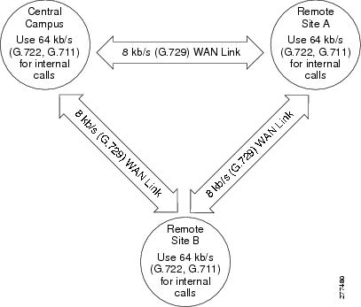
Simple Region Configuration Example
The figure below shows a very simple region configuration example for deployment with a central site and two remote branches. In the example, an administrator configures a region for each site, leaving the Max Audio Bit Rate between the regions as Use System Default. Use System Default means that the values of the Service Parameters for the Max Audio Bit Rate are used. The Default Intraregion Max Audio Bit Rate has a factory default value of 64 kbps (G.722, G.711), while the Default Interregion Max Audio Bit Rate has a factory default value of 8 kbps (G.729).
Add Region
Cisco Unified Communications Manager allows you to add a maximum of 2000 regions.
You must specify the maximum bit rate for devices that are using regions.
| Step 1 | Select in Cisco Unified Communications Manager Administration Service Parameters Configuration window to configure the default values for maximum bit rates for audio and video calls. |
| Step 2 | Choose the node. |
| Step 3 | Choose the Cisco Unified Communications Manager service |
| Step 4 | Scroll to the
Clusterwide Parameters (System-Location and
Region) pane
For enhanced scalability and to ensure that the system uses fewer resources, Cisco recommends that you set the default values in the Service Parameters Configuration window for the maximum bit rates for audio and video calls and the link loss type; then, when you configure regions, choose the default settings in the Region Configuration window. |
| Step 5 | Create regions specifying the maximum bit rates to use for calls
within those regions and between other regions.
|
| Step 6 | Create or modify device pools to use the regions that you created. |
| Step 7 | Assign device pools to devices. |
| Step 8 | Restart devices to apply any changes to devices that use the updated region. |
Device Pools
-
Device Pool Name-Specifies the name for the new device pool.
-
Date/Time group-Specifies the date and time zone for a device.
-
Region-Specifies the audio and video codecs that are used within and between regions. Use regions only if you have different types of codecs within the network.
-
Softkey template-Manages the softkeys that are associated with applications on Cisco Unified IP Phones.
-
Survivable Remote Site Telephony (SRST) reference-Specifies the gateway that provides SRST functionality for the devices in a device pool.
-
Calling search space for auto-registration (optional)-Specifies the partitions that an auto-registered device can reach when a call is placed.
-
Reverted call focus priority (optional)-Specifies which call type, incoming calls or reverted calls, has priority for user actions, such as going off hook. For example, if a phone has both a reverted call and an incoming call alerting, the incoming call gets retrieved on off hook when incoming calls have priority.
-
Media resource group list (optional)-Specifies a prioritized list of media resource groups. An application chooses the required media resource (for example, a Music On Hold server, transcoder, or conference bridge) from the available media resource groups according to the priority order that is defined in the media resource group list.
-
Network hold music on hold (MOH) audio sources (optional)-Specifies the audio source for network hold.
-
User hold music on hold (MOH) audio source (optional)-Specifies the audio source for user hold.
-
Network locale-Contains a definition of the tones and cadences that the phones and gateways use in a device pool in a specific geographic area.
Note
You must choose only a network locale that is already installed and that the associated devices support. The list contains all available network locales for this setting, but not all are necessarily installed. If the device is associated with a network locale that it does not support in the firmware, the device will fail to come up.
-
Device Mobility Group-Represents the highest level entity that is used to control device mobility for this device.
-
Location-Implements call admission control in a centralized call-processing system.
-
Physical Location-Distinguishes the device-mobility-related parameters that apply to a specific geographical location from other parameters.
-
User locale-Identifies a set of detailed information to support users, including language and font. This characteristic associates with the phones and gateways in a device pool.
-
Connection Monitor Duration-Resolves WAN link flapping issues between Cisco Unified Communications Manager and SRST.
-
Single Button Barge/cBarge-Specifies the Single Button Barge/cBarge feature setting.
-
Join Across Lines-Specifies the Join Across Lines feature setting.
-
Device Mobility Calling Search Space-Specifies the appropriate calling search space to be used as the device calling search space when the device is roaming and in same device mobility group.
-
AAR Calling Search Space-Specifies the calling search space for the device to use when performing automated alternate routing (AAR).
-
AAR Group-Specifies the AAR group for this device. The AAR group provides the prefix digits that are used to route calls that are otherwise blocked due to insufficient bandwidth. An AAR group setting of None specifies that no attempt to reroute blocked calls will occur.
-
MLPP Precedence and Preemption Information-Manages MLPP settings: -
MLPP Indication-Specifies whether devices in the device pool that are capable of playing precedence tones will use the capability when the devices plan an MLPP precedence call.
-
MLPP Preemption-Specifies whether devices in the device pool that are capable of preempting calls in progress will use the capability when the devices plan an MLPP precedence call.
-
MLPP Domain-Specifies a hexadecimal value for the MLPP domain that is associated with the device pool. Device pools refer to the configured MLPP domain.
-
-
Calling Party Transformation Pattern CSS and international escape character + (prefix) settings.
Note | You must configure the preceding items before you configure a device pool if you want to choose the items for the device pool. |
After you add a new device pool to the database, you can use it to configure devices such as Cisco Unified IP Phones, gateways, conference bridges, transcoders, media termination points, voice-mail ports, and CTI route points.
If you are using auto-registration, you can assign all devices of a given type to a device pool by using the Device Defaults window in Cisco Unified Communications Manager Administration.
Update Device Pools
If you make changes to a device pool, you must reset the devices in that device pool before the changes will take effect.
You cannot delete a device pool that has been assigned to any devices or one that is used for Device Defaults configuration.
If you try to delete a device pool that is in use, a message displays. Before deleting a device pool that is currently in use, you must perform either or both of the following tasks:
- Update the devices to assign them to a different device pool.
- Delete the devices that are assigned to the device pool that you want to delete.
Common Device Configuration
A common device configuration comprises user-specific service and feature attributes. You can specify the following device characteristics for a common device configuration:
-
Name-Specifies the name for the common device configuration.
-
Softkey Template-Specifies the softkey template that is associated with the devices in the device pool.
-
User Hold MOH Audio Source-Specifies the audio source to use for music on hold (MOH) when a user initiates a hold action.
-
Network Hold MOH Audio Source-Specifies the audio source to use for MOH when the network initiates a hold action.
-
User Locale-Specifies the location that is associated with the phones and gateways in the device pool.
-
MLPP Indication-Specifies whether devices in the device pool that are capable of playing precedence tones will use the capability when the devices place an MLPP precedence call.
-
MLPP Preemption-Specifies whether devices in the device pool that are capable of preempting calls in progress will use the capability when the devices place an MLPP precedence call.
-
MLPP Domain-Specifies the MLPP domain that is associated with this device pool.
LDAP
See the Directory Overview chapter for information about using directories with Cisco Unified Communications Manager.
Call Admission Control
Use call admission control to maintain a desired level of voice quality over a WAN link. For example, you can use call admission control to regulate the voice quality on a 56-kb/s frame relay line that connects your main campus and a remote site.
Voice quality can begin to degrade when too many active calls exist on a link and the amount of bandwidth is oversubscribed. Call admission control regulates voice quality by limiting the number of calls that can be active at the same time on a particular link. Call admission control does not guarantee a particular level of audio quality on the link, but it does allow you to regulate the amount of bandwidth that active calls on the link consume.
Cisco Unified Communications Manager supports two types of call admission control:
-
Locations-Use locations to implement call admission control in a centralized call-processing system. Call admission control lets you regulate voice quality by limiting the amount of bandwidth that is available for calls over links between the locations.
Note | If you do not use call admission control to limit the voice bandwidth on an IP WAN link, the system allows an unlimited number of calls to be active on that link at the same time. This can cause the voice quality of each call to degrade as the link becomes oversubscribed. |
Survivable Remote Site Telephony References
Survivable Remote Site Telephony (SRST) gets used at sites that depend on a Cisco Unified Communications Manager that is accessible via a WAN connection. SRST provides telephony service to IP phones at the remote site in the event of a WAN outage. An SRST-enabled router has features that allow calls between IP phones at the remote site to call each other, allow calls from the PSTN to reach the IP phones, and allow calls from the IP phones to reach the external world through the PSTN. Intelligence in the SRST router that can accept registrations from the IP phones and route calls based on the directory numbers that are registered, and based on the routing that is configured for the PSTN link, accomplishes that.
Survivable remote site telephony (SRST) references, a configurable option in Cisco Unified Communications Manager Administration, provide limited call capability in the event of a WAN outage. Using SRST references, IP gateways can take over limited Cisco Unified Communications Manager functionality. When phones lose connectivity to all associated Cisco Unified Communications Managers, the phones in a device pool attempt to make a Cisco Unified Communications Manager connection to the SRST reference IP gateway.
The status line indication on the IP phone that shows the phone has failed over to the backup proxy (SRST gateway) provides the only user interactions with SRST.
Device Pool Settings for SRST
The system administrator can configure the SRST configuration for a device pool of phones. The following list gives Device Pool configuration options that are available:
-
Disable–If a phone cannot reach any Cisco Unified Communications Managers, it does not try to connect to an SRST gateway.
-
Use Default Gateway–If a phone cannot reach any Cisco Unified Communications Managers, it tries to connect to its IP gateway as an SRST gateway.
-
User-defined–If a phone cannot reach any Cisco Unified Communications Managers, it tries to connect to an administrator-specified SRST gateway. The SRST Reference field of the Device Pool Configuration lists user-defined SRST references.
The administrator defines SRST configurations in the SRST Reference Configuration window. Any preceding SRST configuration option can apply to a device pool. The Cisco TFTP reads the SRST configuration and provides it to the IP phone in a .cnf.xml file. The IP phone reacts appropriately to the SRST configuration.
Connection Monitor Duration
An IP phone that connects to the SRST over a Wide Area Network (WAN) reconnects itself to Cisco Unified Communications Manager as soon as it can establish a connection with Cisco Unified Communications Manager over the WAN link. However, if the WAN link is unstable, the IP phone switches back and forth between the SRST and Cisco Unified Communications Manager. This situation causes temporary loss of phone service (no dial tone). These reconnect attempts, known as WAN link flapping issues, continue until the IP phone successfully reconnects itself to Cisco Unified Communications Manager. These WAN link disruptions fit into two classifications: infrequent random outages that occur on an otherwise stable WAN and the sporadic, frequent disruptions that last a few minutes.
To resolve the WAN link flapping issues between Cisco Unified Communications Manager and SRST, Cisco Unified Communications Manager provides an enterprise parameter and a setting in the Device Pool Configuration window that is called Connection Monitor Duration. Depending upon system requirements, the administrator decides which parameter to use. The value of the parameter gets delivered to the IP phone in the XML configuration file.
-
The default for the enterprise parameter specifies 120 seconds. Use the enterprise parameter to change the connection duration monitor value for all IP phones that are configured in Cisco Unified Communications Manager Administration.
-
Use the Device Pool Configuration window to change the connection duration monitor value for all IP phones in a specific device pool.
SRST Reference Configuration Options for Phones That Are Running SIP
A remote site may have a mix of SCCP and SIP endpoints in addition to PSTN gateway access. For calls to be routed between the different protocols and the PSTN, three different features will get configured in one SRST router that will allow calls to be routed between phones that are running SCCP, phones that are running SIP, and the PSTN during a WAN outage. In addition, the SRST Reference Configuration window in Cisco Unified Communications Manager Administration provides two fields:
-
SIP Network/IP Address-The SIP network/IP address applies for SIP SRST. This address notifies the phone that is running SIP where to send SIP Register message for SIP SRST.
-
SIP Port-SIP port of the SRST gateway. Default specifies 5060.
For more information, see System-Level Configuration Settings.
For information about configuring security for the SRST reference and the SRST-enabled gateway, see the Cisco Unified Communications Manager Security Guide.
MLPP Domain
Because the MLPP service applies to a domain, Cisco Unified Communications Manager only marks a precedence level to connections and resources that belong to calls from MLPP users in a given domain. The MLPP domain subscription of the originating user determines the domain of the call and its connections. Only higher precedence calls in one domain can preempt connections that calls in the same domain are using.
To define an MLPP domain, configure the following MLPP domain information:
-
Domain Name-Name of the MLPP domain.
-
Domain Identifier-Configure the MLPP domain identifier as a hexadecimal value of zero or greater (the default value specifies zero).
The MLPP domain identifier comprises the collection of devices and resources that are associated with an MLPP subscriber. When an MLPP subscriber (who belongs to a particular domain) places a precedence call to another MLPP subscriber (who belongs to the same domain), the MLPP service can preempt the existing call that the called MLPP subscriber is on for a higher precedence call. The MLPP service availability does not cross domains. Device pools refer to the configured MLPP domain.
Note | You must reset all devices for a change to this setting to take effect. |
Enterprise Parameters
Enterprise parameters provide default settings that apply to all devices and services. When you install a new Cisco Unified Communications Manager, it uses the enterprise parameters to set the initial values of its device defaults.
You cannot add or delete enterprise parameters, but you can update existing enterprise parameters. Cisco Unified Communications Manager Administration divides enterprise parameters by categories; for example, CCMAdmin parameters, CCMUser parameters, and CDR parameters.
You can display additional descriptions for enterprise parameters by using the question mark button on the Enterprise Parameters Configuration window.
Service Parameters
Service parameters for Cisco Unified Communications Manager allow you to configure different services on selected servers. You can view a list of parameters and their descriptions by clicking the question mark button that displays on the Service Parameters Configuration window. You can view the list with a particular parameter at the top by clicking that parameter.
If you deactivate a service by using Cisco Unified Serviceability, Cisco Unified Communications Manager retains any updated service parameter values. If you start the service again, Cisco Unified Communications Manager sets the service parameters to the changed values.
Caution | Some changes to service parameters may cause system failure. Cisco recommends that you do not make any changes to service parameters unless you fully understand the feature that you are changing or unless the Cisco Technical Assistance Center (TAC) requests that you make changes. |
Dependency Records
Use dependency records to find specific information about system-level settings such as servers, device pools, and date/time groups.
If the dependency records are not enabled for the system, the dependency records summary window displays a message.
Note | You cannot view dependency records from the Device Defaults and Enterprise Parameters Configuration windows. |
The Cisco Unified CM Configuration Dependency Records window provides information about Cisco Unified Communications Manager groups that it accesses. The Date/Time Group Configuration Dependency Records window provides information about device pools that it accesses.
 Feedback