Cisco Unified Communications Manager System Guide, Release 10.0(1)
Bias-Free Language
The documentation set for this product strives to use bias-free language. For the purposes of this documentation set, bias-free is defined as language that does not imply discrimination based on age, disability, gender, racial identity, ethnic identity, sexual orientation, socioeconomic status, and intersectionality. Exceptions may be present in the documentation due to language that is hardcoded in the user interfaces of the product software, language used based on RFP documentation, or language that is used by a referenced third-party product. Learn more about how Cisco is using Inclusive Language.
- Updated:
- August 28, 2014
Chapter: Call Admission Control
Contents
- Call Admission Control
- Configure Locations
- Configure Gatekeeper and Gatekeeper-Controlled Trunk
- Locations
- Locations and Regions
- Bandwidth Calculations
- Location-Based MLPP
- Location-Based Call Admission Control Over Intercluster Trunk
- Configure Gatekeepers and Trunks
- Components of Gatekeeper Call Admission Control
- Configure Gatekeeper and Trunk on the Router
- Configure Gatekeeper and Trunk in Cisco Unified Communications Manager
Call Admission Control
This chapter provides information about call admission control which enables you to control the audio quality and video quality of calls over a wide-area (IP WAN) link by limiting the number of calls that are allowed on that link at the same time. For example, you can use call admission control to regulate the voice quality on a 56-kb/s frame relay line that connects your main campus and a remote site.
Audio and video quality can begin to degrade when too many active calls exist on a link and the amount of bandwidth is oversubscribed. Call admission control regulates audio and video quality by limiting the number of calls that can be active on a particular link at the same time. Call admission control does not guarantee a particular level of audio or video quality on the link, but it does allow you to regulate the amount of bandwidth that active calls on the link consume.
Call admission control operates by rejecting a call for bandwidth and policy reasons. When a call gets rejected due to call admission control, the phone of the called party does not ring, and the caller receives a busy tone. The caller also receives a message on their phone, such as "Not enough bandwidth."
Without call admission control, you may perceive that IP voice is low in quality and unreliable. With call admission control, customers experience situations similar to the time-division multiplexing (TDM) processing and realize that they need more bandwidth for peak hours.
This section describes two types of call admission control that you can use with Cisco Unified Communications Manager:
-
Locations, for systems with centralized call processing
-
Configure Gatekeepers and Trunks, for systems with distributed call processing
You can choose either of these methods of call admission control, but you cannot combine them in the same Cisco Unified Communications Manager system. If your system does not contain IP WAN links with limited available bandwidth, you do not have to use call admission control.
Cisco Unified Communications Manager also supports Resource Reservation Protocol (RSVP), an additional CAC mechanism that offers additional capabilities for full-mesh network topologies.
- Configure Locations
- Configure Gatekeeper and Gatekeeper-Controlled Trunk
- Locations
- Configure Gatekeepers and Trunks
Configure Locations
Locations, which are available in Cisco Unified Communications Manager, provides call admission control for centralized call-processing systems. Call admission control enables you to control the audio quality and video quality of calls over a wide-area (IP WAN) link by limiting the number of calls that are allowed on that link at the same time. For example, you can use call admission control to regulate the voice quality on a 56-kb/s frame relay line that connects your main campus and a remote site.
Audio and video quality can begin to degrade when too many active calls exist on a link and the amount of bandwidth is oversubscribed. Call admission control regulates audio and video quality by limiting the number of calls that can be active on a particular link at the same time. Call admission control does not guarantee a particular level of audio or video quality on the link, but it does allow you to regulate the amount of bandwidth that active calls on the link consume.
Call admission control operates by rejecting a call for bandwidth and policy reasons. When a call gets rejected due to call admission control, the phone of the called party does not ring, and the caller receives a busy tone. The caller also receives a message on their phone, such as "Not enough bandwidth."
Without call admission control, you may perceive that IP voice is low in quality and unreliable. With call admission control, you may experience situations similar to the time-division multiplexing (TDM) processing and realize that they need more bandwidth for peak hours. If your system does not contain IP WAN links with limited available bandwidth, you do not have to use call admission control.
A centralized system uses a single Cisco Unified Communications Manager cluster to control all the locations.
You can choose to configure locations or to configure gatekeepers and trunks for call admission control, but you cannot combine them in the same Cisco Unified Communications Manager system.
 Note | For non-centralized systems, Cisco Unified Communications Manager offers an alternative CAC method, Resource Reservation Protocol (RSVP). |
The general steps for configuring call admission control on the basis of locations is as follows.
Configure Gatekeeper and Gatekeeper-Controlled Trunk
Call admission control enables you to control the audio quality and video quality of calls over a wide-area (IP WAN) link by limiting the number of calls that are allowed on that link at the same time. For example, you can use call admission control to regulate the voice quality on a 56-kb/s frame relay line that connects your main campus and a remote site.
Audio and video quality can begin to degrade when too many active calls exist on a link and the amount of bandwidth is oversubscribed. Call admission control regulates audio and video quality by limiting the number of calls that can be active on a particular link at the same time. Call admission control does not guarantee a particular level of audio or video quality on the link, but it does allow you to regulate the amount of bandwidth that active calls on the link consume.
Call admission control operates by rejecting a call for bandwidth and policy reasons. When a call gets rejected due to call admission control, the phone of the called party does not ring, and the caller receives a busy tone. The caller also receives a message on their phone, such as "Not enough bandwidth."
Without call admission control, you may perceive that IP voice is low in quality and unreliable. With call admission control, you may experience situations similar to the time-division multiplexing (TDM) processing and realize that they need more bandwidth for peak hours. If your system does not contain IP WAN links with limited available bandwidth, you do not have to use call admission control.
- Gatekeepers reduce configuration overhead by eliminating the need to configure a separate H.323 device for each remote Cisco Unified Communications Manager that is connected to the IP WAN.
- A gatekeeper can determine the IP addresses of devices that are registered with it, or you can enter the IP addresses explicitly.
- The gatekeeper supports the H.323 protocol and uses the H.225 protocol to make calls.
- The gatekeeper can perform basic call routing in addition to call admission control.
Note | See the Cisco Unified Communications Solution Reference Network Design (SRND) for more detailed information about gatekeeper configuration, dial plan considerations when a gatekeeper is used, and gatekeeper interaction with Cisco Unified Communications Manager. |
| Step 1 | On the gatekeeper device, configure the appropriate zones and
bandwidth allocations for the various
Cisco Unified
Communications Managers that will route calls to it.
See "Configuring H.323 Gatekeepers and Proxies", Cisco IOS H.323 Configuration Guide |
| Step 2 | Configure gatekeeper settings in Cisco Unified Communications Manager Administration.Repeat this step for each Cisco Unified Communications Manager that will register with the gatekeeper. Make sure Host Name or IP Address is set the same way on each Cisco Unified Communications Manager. |
| Step 3 | Configure the appropriate intercluster trunks or H.225 trunks to specify gatekeeper information (if gatekeeper-controlled). |
| Step 4 | Configure a route pattern to route calls to each gatekeeper-controlled trunk. |
Locations
The locations feature, which is available in Cisco Unified Communications Manager, provides call admission control for centralized call-processing systems. A centralized system uses a single Cisco Unified Communications Manager cluster to control all the locations. For non-centralized systems, Cisco Unified Communications Manager offers an alternative CAC method, Resource Reservation Protocol (RSVP). See for a description of RSVP.
 Tip | Do not confuse locations with geolocations. Locations, which you configure by using the menu option, allow you to define entities that a centralized call-processing system uses to provide call admission control (CAC). Geolocations, which you configure by using the menu option, allow you to specify geographic locations that you use to associate Cisco Unified Communications Manager devices for features such as logical partitioning. |
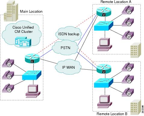
The remote locations (for example, branch offices of your company) house additional phones and other devices, but they do not contain any call-processing capability. The remote locations connect to the main location by means of IP WAN links (and possibly PSTN and ISDN links as backups) and to each other by going through the main location (central campus).
Calls between devices at the same location do not need call admission control because those devices reside on the same LAN, which has unlimited available bandwidth. However, calls between devices at different locations must travel over an IP WAN link, which has limited available bandwidth.
The locations feature in Cisco Unified Communications Manager lets you specify the maximum amount of audio bandwidth (for audio calls) and video bandwidth (for video calls) that is available for calls to and from each location, which thereby limits the number of active calls and limits oversubscription of the bandwidth on the IP WAN links.
Note | Each audio call includes two streams, one in each direction. Video calls have four or six streams (that is, two or three streams in each direction). |
Location Example
|
Location |
Bandwidth (kb/s) |
|---|---|
|
San Francisco (main location) |
Unlimited |
|
Austin (remote location) |
160 |
|
Dallas (remote location) |
200 |
Cisco Unified Communications Manager continues to admit new calls to a link as long as sufficient bandwidth is still available. Thus, if the link to the Austin location in the example has 160 kb/s of available bandwidth, that link can support two G.711 calls at 80 kb/s each, six G.723 or G.729 calls at 24 kb/s each, or five GSM calls at 29 kb/s each. If any additional calls try to exceed the bandwidth limit, the system rejects them, the calling party receives reorder tone, and a text message displays on the phone.
Audio Bandwidth
When you configure a location in Cisco Unified Communications Manager Administration, you assign it a name and maximum audio bandwidth. If you set the audio or video bandwidth to Unlimited, you allocate unlimited available bandwidth and allow an unlimited number of active calls on the IP WAN link for that location. In configuring a location, you also assign a video bandwidth for the location. If you set the video bandwidth setting to None, no video calls can connect between this location and other locations, but they can take place within this location.
When you configure a phone or other device in Cisco Unified Communications Manager Administration, you can assign it to a location. If you set the location to Hub_None, you assign that device to an unnamed location with unlimited available bandwidth and allow an unlimited number of active calls to and from that device.
Location reservations move to reflect the type of call. When a call changes from video to audio-only, the location reservation moves from the video location to an audio location. Calls that change from audio-only to video cause the opposite change of location reservation.
- Locations and Regions
- Bandwidth Calculations
- Location-Based MLPP
- Location-Based Call Admission Control Over Intercluster Trunk
Locations and Regions
Locations work in conjunction with regions to define the characteristics of a network link. Regions define the type of compression (G.711, G.722, G.723, G.729, GSM, or wideband) that is used on the link, and locations define the amount of available bandwidth for the link. You assign each device in the system to both a region (by means of a device pool) and a location.
Bandwidth Calculations
In performing location bandwidth calculations for purposes of call admission control, Cisco Unified Communications Manager assumes that each call stream consumes the following amount of bandwidth:
-
G.711 call uses 80 kb/s.
-
G.722 call uses 80 kb/s.
-
G.723 call uses 24 kb/s.
-
G.728 call uses 26.66 kb/s.
-
G.729 call uses 24 kb/s.
-
GSM call uses 29 kb/s.
-
Wideband call uses 272 kb/s.
-
iLBC call uses 24 kb/s.
-
AMR call uses 12.2 kb/s.
-
AMR-WB call uses 23.85 kb/s.
-
AAC call uses value that video mline specifies.
Note | Each audio call comprises two call streams. Actual bandwidth consumption per call varies, depending on factors such as data packet size. Cisco Unified Communications Manager uses these fixed values to simplify the bandwidth calculations for purposes of the locations feature only. Each video call can comprise four or six call streams. For a video call, total bandwidth represents the sum of the call audio bandwidth plus video bandwidth but does not include the call overhead. |
The audio bandwidth value that is specified for a location includes overhead, whereas the video bandwidth value that is specified for a location does not include overhead. For a location, the bandwidth that is available for video calls represents the sum of the audio bandwidth and the video bandwidth. See the Video Telephony chapter for more details.
Cisco Unified Communications Manager allows calls to complete over a link until sufficient bandwidth does not exist for a new call. At that point, any additional calls fail, and the calling party receives reorder tone.
When a link to a location experiences blockage, it may result from bandwidth leakage that has reduced the usable bandwidth for the location. You can resynchronize the bandwidth allotment to the maximum setting for the location without restarting the Cisco Unified Communications Manager server.
Note | If you resynchronize the bandwidth for a location when calls are using the link, the bandwidth might be oversubscribed until all calls that are using the link disconnect. An oversubscribed link can cause audio and video quality to degrade. For this reason, resynchronize the location bandwidth during hours when the link has low traffic. |
Media Termination Point (MTP) and transcoder represent exceptions to the bandwidth rules that are outlined in the preceding paragraph. Calls that are made through an MTP can complete even if they exceed the available bandwidth limit. Calls that are made through an MTP, however, cannot provide video.
 Caution | In the United States and Canada, routing an emergency 911 call to a link that has no more available bandwidth can block the 911 call. For each location on your network, always route 911 calls to the local public switched telephone network (PSTN) through a local VoIP gateway. |
See the "Regions" subtopic under the "Administration Considerations" topic of the "IP Video Telephony" chapter of the Cisco Unified Communications Solution Reference Network Design (SRND) for the current release, which provides recommendations as to how the video bandwidth should be set for regions and locations, so the video portion of video calls will succeed, and the video calls will not get rejected nor set up as audio-only calls.
Location-Based MLPP
Cisco Unified Communications Manager supports MLPP on phones that run SCCP and TDM (PRI/CAS) trunks. Cisco Unified Communications Manager also supports MLPP on wide-area network (WAN) links. Location-based call admission control (CAC) manages WAN link bandwidth in Cisco Unified Communications Manager. Enhanced locations take into account the precedence level of calls and preempt calls of lower precedence when necessary to accommodate higher precedence calls.
Enhancing locations mean that, when a precedence call arrives and not enough bandwidth can be found to connect the call to the destination location, Cisco Unified Communications Manager finds the call or calls with the lowest precedence level and preempts the call(s) to make sufficient bandwidth available for a higher precedence call. If the bandwidth requirement still cannot be satisfied after going through the preemption procedure, the newly placed call fails.
Location based MLPP allows you to configure a set of destinations as nonpreemptable. The calls on the nonpreemptable numbers are not disconnected even if a higher precedence call is attempted. To support this feature, LBM additionally checks for the nonpreemptable status of the call leg that is updated in the PolicyAndCAC messages along with the service parameter MLPP Exception Level before preempting a call.
Location-Based Call Admission Control Over Intercluster Trunk
When a call gets made across cluster through an intercluster trunk (ICT) and gets hairpinned back to the same location or site of the same cluster, although the media gets exchanged between two endpoints in the same site or location, the previous design of Cisco Unified Communications Manager location call admission control (CAC) deducted location bandwidth twice, once for the outbound call and again for the inbound call. The result did not correctly reflect the bandwidth consumption, which eventually caused denial of a new call to or from the site or location.
To resolve the bandwidth calculation problem, this feature enables Cisco Unified Communications Manager to pass location information, the primary key ID (PKID) of location record and location name, as a proprietary information element (IE) between the calling and called parties through an ICT, either in the H.323 protocol or SIP. Thus, either endpoint knows the true location information of the party/endpoint, not the location information of the ICT.
Cisco Unified Communications Manager previously identified Hub_None as the default location that has unlimited bandwidth, plus any user-created location to which the user can assign a device and for which the user can configure bandwidth.
A Cisco Unified Communications Manager location gets created specifically for the ICT for this type of application. This location, designated as the Phantom location, also has unlimited bandwidth. The locations server does not deduct bandwidth for a device that is assigned to the Phantom location. A device, such as the ICT, that is assigned to the Phantom location can use its own location or the true location of the connected device. Likewise, the outbound ICT can use its own location or the callee location, and the inbound ICT can use its own location or the caller location to deduct or adjust the bandwidth.
When the media connects, Cisco Unified Communications Manager adjusts the allocated location bandwidth according to the negotiated media codec. Cisco Unified Communications Manager can correctly readjust the location bandwidth on the basis of received callee location information for the outbound call. This enhancement helps the outbound call, which has reserved bandwidth during call setup time, to adjust the bandwidth back to 0 if the call gets hairpinned back to the same site or location.
Some supplementary services, such as transfer, can also hairpin the call back to the same site or location after the initial call setup process. Be aware that passing the location information of the final destination through the Notify signals (H.323) and re-INVITE signals (SIP) back to the calling cluster, so bandwidth can be adjusted to the right value, is also required.
Because location record PKID is uniquely defined within the Cisco Unified Communications Manager enterprise environment, Cisco Unified Communications Manager uses location record PKID to identify whether the call over ICT has looped back to the same cluster for the location-based CAC purpose. If other applications, like Cisco Voice Proxy (CVP), do not have access to the Cisco Unified Communications Manager database for location record PKID information, which comprises a string of characters and digits, applications may need to rely on the location name information that is getting passed around for the purpose of CAC. The same location name may exist for different locations with different location PKIDs in two different Cisco Unified Communications Manager clusters, which may cause confusion to the applications.
Cisco Unified Communications Manager Administration Configuration Tips
The Location Configuration window specifies the Phantom location as a location, besides the Hub_None location, that can get selected. Administrators cannot delete the Phantom location.
Administrators can create a default location for the Phantom location, similar to the Hub_None location. The Phantom location includes unlimited audio and video bandwidth value, and the administrator cannot modify the audio and video bandwidth values. The user can assign a location-pair RSVP policy between this location and other existing locations.
This feature does not entail any additional menu options or fields in Cisco Unified Communications Manager Administration. The Phantom value gets added for all entities that specify a location in the Location drop-down list box. You can find the Location field on the Device Pool Configuration, Annunciator Configuration, Music On Hold (MOH) Server Configuration, Conference Bridge Configuration, Voice Mail Port Configuration, Voice Mail Port Wizard Configuration, CTI Route Point Configuration, Gateway Configuration, Phone Configuration, Trunk Configuration, and Pilot Point Configuration windows.
Cisco Unified Communications Manager maintains the RSVP policy for the Phantom location during migration.
Tip | If the intercluster trunk or H.323 gateway gets configured in any other location besides the Phantom location, this feature does not work. In addition, if the intercluster trunk is connected to a third-party system that does not recognize and pass the Cisco-specific location information in the SIP or H.323 signals, this feature does not work. |
Configure Gatekeepers and Trunks
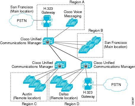
A gatekeeper device, the Cisco Multimedia Conference Manager (MCM), provides call admission control for distributed call-processing systems. In a distributed system, each site contains its own call-processing capability.
Sometimes an anonymous H.323 device, a device that is not known to Cisco Unified Communications Manager, tries to initiate (send or receive) calls with Cisco Unified Communications Manager. This anonymous device could be a Cisco IOS product (such as a gateway) or any third-party H.323 device.
You can configure H.323 gateways either with gatekeeper control or locally as gateways.
| Step 1 | Select . | ||||||||
| Step 2 | Choose an option from the
Trunk Type drop-down list box.
| ||||||||
| Step 3 | Configure the appropriate fields when the Trunk Configuration window displays. |
Call Admission Control Example
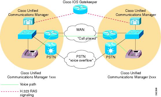
In addition to call admission control, gatekeepers can perform E.164 address resolution to route calls between sites. In this example, the extension range for one Cisco Unified Communications Manager specifies 1XXX and 2XXX for the other. Both register with the gatekeeper for call admission control. Each Cisco Unified Communications Manager incorporates an appropriate entry in its respective dial plan route pattern configuration that points the other Cisco Unified Communications Manager extension number range to the gatekeeper. In practice, when user 1001 dials user 2002, Cisco Unified Communications Manager 1XXX sends 2002 to the gatekeeper for address resolution. If the call satisfies the call admission control criteria, the gatekeeper returns the IP address of Cisco Unified Communications Manager 2XXX to Cisco Unified Communications Manager 1XXX. Using the IP address of Cisco Unified Communications Manager 2XXX, Cisco Unified Communications Manager 1XXX can then complete the call to directory number 2002.
If the IP WAN is not available in this scenario, the call cannot go through as dialed. To simplify the dial plan and also provide fallback to the PSTN, use 10-digit dialing (or adhere to the national dial plan). For example, under the North American Numbering Plan (NANP), a route pattern of XXXXXXXXXX would direct calls to the gatekeeper for address resolution. If the gatekeeper does not allow the call to go over the WAN, Cisco Unified Communications Manager can add the prefix 91 to the dialed digits to reroute the call through the PSTN.
See the Cisco Unified Communications Solution Reference Network Design (SRND) for more detailed information about gatekeeper configuration, dial plan considerations when a gatekeeper is used, and gatekeeper interaction with Cisco Unified Communications Manager.
Components of Gatekeeper Call Admission Control
Gatekeeper call admission control provides great flexibility:
-
Gatekeepers reduce configuration overhead by eliminating the need to configure a separate H.323 device for each remote Cisco Unified Communications Manager that is connected to the IP WAN.
-
A gatekeeper can determine the IP addresses of devices that are registered with it, or you can enter the IP addresses explicitly.
-
The gatekeeper supports the H.323 protocol and uses the H.225 protocol to make calls.
-
The gatekeeper can perform basic call routing in addition to call admission control.
- Configure Gatekeeper and Trunk on the Router
- Configure Gatekeeper and Trunk in Cisco Unified Communications Manager
Configure Gatekeeper and Trunk on the Router
Recommended platforms for the gatekeeper include Cisco 2600, 3600, 3700, or 7200 routers with Cisco IOS Release 12.1(3)T or higher. When configuring the gatekeeper function on one of these routers, you define a set of zones for call admission control. The unique name for each zone includes the IP address of each Cisco Unified Communications Manager that registers with that zone, the zone prefix (directory number range), and the bandwidth that is allocated for that zone.
Cisco Unified Communications Manager registers with a gatekeeper by using its IP address. You can specify the IP address in one of the following ways:
- Use the gw-type-prefix command on the gatekeeper to specify each Cisco Unified Communications Manager IP address explicitly.
- In the Technology Prefix field under in Cisco Unified Communications Manager Administration, enter 1#* and enter the command gw-type-prefix 1#* default-technology on the gatekeeper. When a Cisco Unified Communications Manager registers with the gatekeeper, it sends its IP address and the specified technology prefix to the gatekeeper. The gatekeeper then registers this Cisco Unified Communications Manager as a valid gatekeeper-controlled VoIP device.
You associate the Cisco Unified Communications Manager IP address with a particular zone by performing the following steps:
- Use the zone local command on the gatekeeper to define local zones. Enter the zone name in the Zone field.
- In the Zone field under in Cisco Unified Communications Manager Administration, enter the zone name. When a Cisco Unified Communications Manager registers with the gatekeeper, it sends its IP address and the specified zone name to the gatekeeper. The gatekeeper then registers each Cisco Unified Communications Manager and associates it with the appropriate zone.
To specify the directory number range for a particular Cisco Unified Communications Manager, you use the zone prefix command to configure the range on the gatekeeper. For example, the following command specifies that the DN for zone LHR ranges from 3000 to 3999.
zone prefix LHR 3...
The maximum number of active calls that are allowed per zone depends on the codec that is used for each call and the bandwidth that is allocated for the zone. With Cisco Unified Communications Manager, G.711 calls request 128 kb/s, and G.723 and G.729 calls request 20 kb/s. Use regions in Cisco Unified Communications Manager to specify the codec type and use the bandwidth total zone command on the gatekeeper to specify the available bandwidth. For example, the following command allocates 512 kb/s to the LHR zone.
bandwidth total zone LHR 512
With an allocation of 512 kb/s, the LHR zone in this example could support up to four G.711 calls at the same time.
Configure Gatekeeper and Trunk in Cisco Unified Communications Manager
You can configure gatekeepers and trunks in Cisco Unified Communications Manager Administration to function in either of the following ways:
Non-Gatekeeper-Controlled Trunks
In this case, you explicitly configure a separate intercluster trunk for each remote device cluster that the local Cisco Unified Communications Manager can call over the IP WAN. You also configure the necessary route patterns and route groups to route calls to and from the various intercluster trunks. The intercluster trunks statically specify the IP addresses of the remote devices. To choose this method, use and select Inter-Cluster Trunk (Non-Gatekeeper Controlled) in Cisco Unified Communications Manager Administration.
Note | For a local non-gatekeeper-controlled intercluster trunk, you must specify the IP addresses of all remote Cisco Unified Communications Manager nodes that belong to the device pool of the remote non-gatekeeper-controlled intercluster trunk. |
In this case, a single intercluster trunk suffices for communicating with all remote clusters. Similarly, you need a single H.225 trunk to communicate with any H.323 gatekeeper-controlled endpoints. You also configure route patterns or route groups to route the calls to and from the gatekeeper. In this configuration, the gatekeeper dynamically determines the appropriate IP address for the destination of each call to a remote device, and the local Cisco Unified Communications Manager uses that IP address to complete the call.
This configuration works well in large as well as smaller systems. For large systems where many clusters exist, this configuration helps to avoid configuring individual intercluster trunks between each cluster. To choose this method, use and select Inter-Cluster Trunk (Gatekeeper Controlled) in Cisco Unified Communications Manager Administration.
If you configure gatekeeper-controlled trunks, Cisco Unified Communications Manager automatically creates a virtual trunk device. The IP address of this device changes dynamically to reflect the IP address of the remote device as determined by the gatekeeper. Use trunks when configuring the route patterns or route groups that route calls to and from a gatekeeper.