Cisco HyperFlex 4.0 Stretched Cluster with Cisco ACI 4.2 Multi-Pod Fabric Design Guide
Available Languages
Bias-Free Language
The documentation set for this product strives to use bias-free language. For the purposes of this documentation set, bias-free is defined as language that does not imply discrimination based on age, disability, gender, racial identity, ethnic identity, sexual orientation, socioeconomic status, and intersectionality. Exceptions may be present in the documentation due to language that is hardcoded in the user interfaces of the product software, language used based on RFP documentation, or language that is used by a referenced third-party product. Learn more about how Cisco is using Inclusive Language.
- US/Canada 800-553-2447
- Worldwide Support Phone Numbers
- All Tools
 Feedback
 Feedback

Cisco HyperFlex 4.0 Stretched Cluster with Cisco ACI 4.2 Multi-Pod Fabric Design Guide
Published: July 2020
About the Cisco Validated Design Program
The Cisco Validated Design (CVD) program consists of systems and solutions designed, tested, and documented to facilitate faster, more reliable, and more predictable customer deployments. For more information, go to:
http://www.cisco.com/go/designzone.
ALL DESIGNS, SPECIFICATIONS, STATEMENTS, INFORMATION, AND RECOMMENDATIONS (COLLECTIVELY, "DESIGNS") IN THIS MANUAL ARE PRESENTED "AS IS," WITH ALL FAULTS. CISCO AND ITS SUPPLIERS DISCLAIM ALL WARRANTIES, INCLUDING, WITHOUT LIMITATION, THE WARRANTY OF MERCHANTABILITY, FITNESS FOR A PARTICULAR PURPOSE AND NONINFRINGEMENT OR ARISING FROM A COURSE OF DEALING, USAGE, OR TRADE PRACTICE. IN NO EVENT SHALL CISCO OR ITS SUPPLIERS BE LIABLE FOR ANY INDIRECT, SPECIAL, CONSEQUENTIAL, OR INCIDENTAL DAMAGES, INCLUDING, WITHOUT LIMITATION, LOST PROFITS OR LOSS OR DAMAGE TO DATA ARISING OUT OF THE USE OR INABILITY TO USE THE DESIGNS, EVEN IF CISCO OR ITS SUPPLIERS HAVE BEEN ADVISED OF THE POSSIBILITY OF SUCH DAMAGES.
THE DESIGNS ARE SUBJECT TO CHANGE WITHOUT NOTICE. USERS ARE SOLELY RESPONSIBLE FOR THEIR APPLICATION OF THE DESIGNS. THE DESIGNS DO NOT CONSTITUTE THE TECHNICAL OR OTHER PROFESSIONAL ADVICE OF CISCO, ITS SUPPLIERS OR PARTNERS. USERS SHOULD CONSULT THEIR OWN TECHNICAL ADVISORS BEFORE IMPLEMENTING THE DESIGNS. RESULTS MAY VARY DEPENDING ON FACTORS NOT TESTED BY CISCO.
CCDE, CCENT, Cisco Eos, Cisco Lumin, Cisco Nexus, Cisco StadiumVision, Cisco TelePresence, Cisco WebEx, the Cisco logo, DCE, and Welcome to the Human Network are trademarks; Changing the Way We Work, Live, Play, and Learn and Cisco Store are service marks; and Access Registrar, Aironet, AsyncOS, Bringing the Meeting To You, Catalyst, CCDA, CCDP, CCIE, CCIP, CCNA, CCNP, CCSP, CCVP, Cisco, the Cisco Certified Internetwork Expert logo, Cisco IOS, Cisco Press, Cisco Systems, Cisco Systems Capital, the Cisco Systems logo, Cisco Unified Computing System (Cisco UCS), Cisco UCS B-Series Blade Servers, Cisco UCS C-Series Rack Servers, Cisco UCS S-Series Storage Servers, Cisco UCS Manager, Cisco UCS Management Software, Cisco Unified Fabric, Cisco Application Centric Infrastructure, Cisco Nexus 9000 Series, Cisco Nexus 7000 Series. Cisco Prime Data Center Network Manager, Cisco NX-OS Software, Cisco MDS Series, Cisco Unity, Collaboration Without Limitation, EtherFast, EtherSwitch, Event Center, Fast Step, Follow Me Browsing, FormShare, GigaDrive, HomeLink, Internet Quotient, IOS, iPhone, iQuick Study, LightStream, Linksys, MediaTone, MeetingPlace, MeetingPlace Chime Sound, MGX, Networkers, Networking Academy, Network Registrar, PCNow, PIX, PowerPanels, ProConnect, ScriptShare, SenderBase, SMARTnet, Spectrum Expert, StackWise, The Fastest Way to Increase Your Internet Quotient, TransPath, WebEx, and the WebEx logo are registered trademarks of Cisco Systems, Inc. and/or its affiliates in the United States and certain other countries.
All other trademarks mentioned in this document or website are the property of their respective owners. The use of the word partner does not imply a partnership relationship between Cisco and any other company. (0809R)
© 2020 Cisco Systems, Inc. All rights reserved.
Table of Contents
ACI Constructs in an ACI Multi-Pod Fabric
Accessing Outside Networks and Services
Onboarding HyperFlex Virtual Server Infrastructure
Virtual Server Infrastructure Design
Cisco UCS Networking for HyperFlex Infrastructure
Cisco HyperFlex Infrastructure Connectivity
HyperFlex Stretched Cluster Recommendations
Validated Hardware and Software
Application and data availability are an essential component of business success. Fueled by digital transformation, businesses are increasingly seeing a need for continuous 24x7 access to their data and applications. Today’s applications are increasingly containerized or virtualized, and consolidated onto shared infrastructure. The collective impact of an infrastructure failure in this environment is therefore far more catastrophic. As a result, the uptime and availability requirements for the data center infrastructure hosting the applications are also much higher.
To address infrastructure availability, data center architectures typically focus on the resiliency of individual components or sub-systems within the data center. Though reliability and robustness of these components and sub-systems are critical, it does not address data center-wide outages that can cripple a business. In the most mission-critical data centers, it is therefore essential to have an infrastructure solution that can failover to second data center in the event of a failure in the first. Such a solution would ensure that if a disaster or a failure of similar magnitude occurs, the second data center can take over to provide business continuity by providing customers and users access to their applications and data.
The Cisco HyperFlex Stretched Cluster with Cisco ACI Multi-Pod Fabric solution, which is the focus of this document, is a data center infrastructure solution for providing disaster avoidance and business continuity in the most mission-critical of Enterprise data centers. The solution uses an active-active data center design for the Virtualized Server Infrastructure (VSI) to ensure access to at least one data center at all times. The virtualized server infrastructure in the solution is a Cisco HyperFlex stretched cluster with individual servers or nodes in the cluster distributed across both data centers. A Cisco Application Centric Infrastructure (ACI) Multi-Pod fabric provides the network fabric in each data center and also interconnects the two data centers. The ACI Multi-Pod fabric provides Layer 2 extension and Layer 3 forwarding between the data centers, enabling applications to be deployed in either data center location with seamless connectivity and mobility. The two active-active data centers in the solution can be in the same site such as different buildings in a campus location or in different geographical sites across a large metropolitan area. A Cisco ACI Multi-Pod fabric can support a distance of ~4000km between sites for a maximum round-trip time (RTT) of 50ms while a Cisco HyperFlex stretched cluster can support a maximum RTT of 5ms or ~100km between sites. The HyperFlex requirements are more stringent in order to meet the read and write storage latency requirements of Enterprise applications deployed on the cluster.
The Cisco HyperFlex Stretched Cluster with Cisco ACI Multi-Pod Fabric solution is based on Cisco HyperFlex 4.0, Cisco Unified Computing System (Cisco UCS) Manager 4.0, VMware vSphere 6.7, and Cisco ACI 4.2. This document serves as the design guide for the solution. The deployment guide for the solution is available at: https://www.cisco.com/c/en/us/td/docs/unified_computing/ucs/UCS_CVDs/hx_40_vsi_aci_multipod.html
The QoS design used in the solution is discussed in a separate whitepaper available at: https://www.cisco.com/c/dam/en/us/products/collateral/hyperconverged-infrastructure/hyperflex-hx-series/qos-for-hyperflex-wp.pdf
This solution is also part of Cisco’s portfolio of Virtual Server Infrastructure solutions. For a complete list of Cisco HyperFlex VSI solutions, see: https://www.cisco.com/c/en/us/solutions/design-zone/data-center-design-guides/data-center-hyperconverged-infrastructure.html
Introduction
The Cisco HyperFlex Stretched Cluster with Cisco ACI Multi-Pod Fabric solution presented in this document is a validated reference architecture for disaster avoidance and business continuity in Enterprise data centers. The solution uses an active-active data center design to ensure availability to at least one data center in the event of a failure. The solution consists of a single Cisco HyperFlex stretched cluster that is stretched across the active-active data center locations. The individual HyperFlex servers or nodes in the cluster are attached to a pair of Cisco Unified Computing System (Cisco UCS) Fabric Interconnects in each location and connected to a Cisco ACI Multi-Pod fabric that interconnects the data centers. The ACI Multi-Pod fabric provides Layer 2 extension and Layer 3 forwarding, enabling workloads to be placed in either location with seamless mobility and access to the same networks and services. The HyperFlex stretch cluster serves as an Application cluster in this design. The design also includes a HyperFlex standard cluster (optional) for hosting management and operational tools directly from the ACI fabric. Infrastructure outside the ACI fabric is also leveraged and serves as a third location for key services such as HyperFlex Witness and VMware vCenter that a HyperFlex stretch cluster requires. HyperFlex servers and Cisco UCS Fabric Interconnects in both data centers are also centrally managed from the cloud using Cisco Intersight. Cisco Intersight is also used to deploy the management cluster in the solution. The design also includes a sample QoS design to ensure that HyperFlex storage traffic receives the bandwidth and priority it needs. To ease day-2 operations, the design also includes operational tools that can be deployed to monitor and operate the solution.
Audience
Purpose of this Document
What’s New in this Release?
This release of the solution is an update to the earlier Cisco HyperFlex Stretched Cluster with Cisco ACI Multi-Pod fabric solution for delivering a disaster avoidance and business continuity in Enterprise data centers. The updated components in this release of the solution are:
· Cisco HyperFlex 4.0(2b), Cisco UCS Manager 4.0(4h), Cisco Intersight
· Cisco ACI 4.2(4i), VMware vDS 6.6.0 and VMware vSphere 6.7U3
This release also includes updated features from Cisco Intersight. Cisco Intersight is a cloud-based Software-as-a-Service (SAAS) Management platform and therefore, features and capabilities are continuously being added that customers can leverage for their environments. For a list of features and updates to Cisco Intersight since the previous release of this solution, see: https://intersight.com/help/whats_new/2020.
This release of the solution also adds the following operational tools to the solution to simplify day-2 operations through pro-active intelligence and analytics.
· Cisco Network Insights – Advisor (NIA)
· Cisco Network Insights – Resources (NIR)
· Cisco Network Assurance Engine (NAE)
Cisco Network Insight tools are hosted on a 3-node Cisco Application Services Engine cluster connected to the in-band management network of the ACI fabric. To support these operational tools, Precision Time Protocol (PTP) was also enabled on the ACI Fabric.
Solution Summary
The Cisco HyperFlex Stretched Cluster with Cisco ACI Multi-Pod Fabric solution is a hyperconverged virtual server infrastructure solution that uses an active-active data center design to ensure the availability of the virtual server infrastructure in the event of a disaster or a data center-wide failure. The solution uses the following family of infrastructure components for the compute, storage, networking, and virtualization layers of the VSI stack in each data center.
· Cisco HyperFlex (Cisco HX) servers
· Cisco Unified Computing System (Cisco UCS)
· Cisco Application Centric Infrastructure (Cisco ACI) fabric
· Nexus 9000 family of switches (for ACI fabric and Inter-Pod Network)
· VMware vSphere
The solution incorporates technology, design and product best practices and uses a highly resilient design across all layers of the solution. The solution uses a Cisco HyperFlex stretched cluster to provide the hyperconverged virtual server infrastructure in the active-active data centers. The two data centers can be in the same site such as different buildings in a campus location or in different geographical locations. When there is a failure in one location, stretched clusters provide quick recovery by providing availability to virtual machines and data from the second data center location. Stretched clusters ensure zero data loss by maintaining copies of the stored data in both locations. To meet the latency requirements of Enterprise applications hosted on the cluster, the maximum RTT and bandwidth of a stretched cluster must be <5ms (~100km) and require at least 10Gbps between sites for every stretched cluster. The data centers were interconnected by a 75km fiber spool for validation in Cisco labs.
A Cisco ACI Multi-Pod fabric provides the Layer 2 extension and Layer 3 forwarding necessary for enabling the active-active data centers. In this design, the ACI Multi-Pod fabric consists of an ACI fabric in each data center location and an Inter-Pod Network (IPN) to interconnect them. The fabric in each site is referred to as a Pod in the ACI Multi-Pod architecture. Each Pod is deployed as a standard Spine-Leaf architecture (same as a single site fabric) and uses a highly resilient design to access networks and services within the Pod as well as outside the Pod. The design uses 40GbE links for connectivity within each Pod, and 10GbE for connectivity to APICs, IPN and to networks outside the ACI fabric. The connectivity to UCS domains and HyperFlex clusters use either 10GbE or 40GbE in this solution though other links speeds are also supported.
The two HyperFlex clusters in the design are – a HyperFlex stretched cluster as an Application cluster and an optional HyperFlex standard cluster as a Management cluster for hosting operational and other services from within the ACI fabric. Cisco APIC manages the virtual networking on both clusters by integrating with the Virtual Machine Manager (VMM) or VMware vCenter that manages the HyperFlex clusters. For virtual switching, the solution supports both VMware vDS and Cisco AVE – however, this release of the solution was validated using VMware vDS.
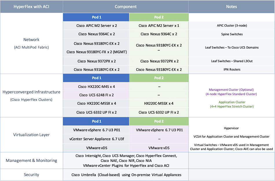
The solution was then built and verified in the Cisco labs using specific models of the different component families (HyperFlex, Cisco UCS, ACI, VMware). Table 1 lists the components in each site.
Table 1 Solution Components per Pod
The solution leverages multiple operational tools, each offering unique capabilities for day-2 operations to manage the different sub-systems in the solution. The tools used in this solution are:
· Cisco Intersight is used to centrally manage the virtual server infrastructure in both data centers. Cisco Intersight is a subscription-based, cloud service with embedded intelligence for managing Cisco and third-party infrastructure. It can simplify day-2 operations by providing pro-active, actionable intelligence for operations such as pro-active support through Cisco Technical Assistance Center (TAC) integration, compliance verification through Cisco Hardware Compatibility List (HCL) integration, etc. Cloud-based delivery using a SAAS management model, also enables Cisco Intersight to continuously roll out new features and functionalities that Enterprises can quickly adopt.
· Cisco Network Assurance Engine is used in the solution to pro-actively ensure that the data center fabric is operating correctly. It uses Cisco’s patented network verification technology to verify that the fabric is operating consistent with the administrator’s intent.
· Cisco Network Insights Advisor (NIA) and Cisco Network Insights Resources (NIR) are used in the solution to monitor, collect and analyze telemetry data from the data center fabric. They can pro-actively identify issues and anomalies, and also drill-down to root-cause and resolve the issues. The tool can monitor resources on an ongoing basis to provide guidance for capacity planning. Cisco NIA can also provide deployment-specific support by delivering pro-active notifications on critical bugs, security advisories, best-practices and software/hardware recommendations that are specific to the environment.
· Disaster avoidance and business continuity in the event of a data center failure
· Direct access to networks and services from each data center location
· Ability to position workloads in either data center location with workload mobility between data centers
· Distribution and active management of workloads across both data center locations
· Site Affinity where virtual machine data is local to the data center
· Quick recovery and zero data-loss in the event of a failure
· Simplified administration and operation of the active-active data centers
The virtual server infrastructure in a given data center was designed to meet the following key goals. These goals are the same as that of a single data center solution:
· Resilient design across all layers of the infrastructure with no single point of failure
· Scalable design with the ability to independently scale compute, storage, and network bandwidth as needed
· Modular design where components, resources or sub-systems can be modified or upgraded to meet business needs
· Flexible design with design options for the different sub-systems in the solution, including the individual components used, storage configuration and connectivity options.
· Ability to automate and simplify by enabling integration with external automation and orchestration tools
· Incorporates technology and product-specific best practices for all components used in the solution
Topology
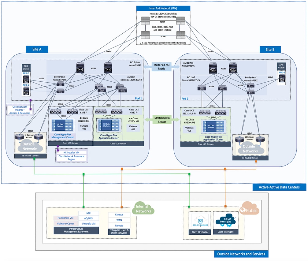
The end-to-end design for the active-active data center solution is shown in Figure 1.
Design Overview
This section provides a high-level summary of the design used in the solution. The design incorporates and aligns with the best practices for the technologies and products used in the solution, as well as general design best practices.
· Design uses an active-active data center architecture to ensure the availability of the virtual server infrastructure in at least one data center in the event of a disaster or a data center-wide failure.
· Cisco HyperFlex provides the hyperconverged compute, storage, and access layer networking for the virtual server infrastructure in the active-active data centers. HyperFlex servers in each data center connect to a pair of Cisco UCS Fabric Interconnects (FI) that provide server management and network connectivity to the upstream ACI fabric. The Fabric Interconnects in each data center connect to a pair of ACI leaf switches in that location.
· Design includes two types of Hyperflex clusters – a HyperFlex stretched cluster for hosting critical Enterprise Applications that must be available at all times, and a HyperFlex standard cluster for Management. In this design, the Management HyperFlex cluster is optional and hosts operational tools and other services. This design also leverages infrastructure in a third location to host key services that are necessary for the proper operation and functioning of the HyperFlex stretched cluster.
· The HyperFlex stretched cluster provides high-availability for the hyperconverged virtual server infrastructure in each data center by extending the cluster across two data centers and by ensuring access to that cluster, the virtual machines hosted on it and the associated storage data from both locations. In the event of a data center wide-failure, the application virtual machines and the virtual machine data will be made available from the second data center. The data centers can be in a single site such as a campus environment or in geographically separate locations such as a metropolitan area. To validate this design, the data centers were assumed to be in different geographical locations, separated by a distance of 75km.
· The optional Management cluster in the design is used to host management and operational tools as needed. The management cluster connects to the ACI fabric and serves as a starting point for deploying and managing additional HyperFlex clusters connected to the same ACI Multi-Pod fabric. For example, the HyperFlex installer that was used to deploy the HyperFlex stretched cluster was hosted on the Management cluster in this design.
· The data center network fabric for the virtual server infrastructure in each active-active data center location is provided by a Cisco ACI Multi-Pod Fabric. Cisco ACI brings software-defined networking (SDN) and a policy-based, application-centric approach to networking that greatly simplifies the administration and rollout of applications and services. ACI Multi-Pod fabric provides the Layer 2 extension and Layer 3 connectivity necessary to extend the virtual server infrastructure and provide seamless workload placement and mobility between the two active-active locations .
· Cisco ACI Multi-Pod fabric consists of distinct ACI fabrics or Pods interconnected by an Inter-Pod Network (IPN). Each fabric or Pod is essentially an independent, standalone ACI fabric, similar to a single-site ACI fabric. Two Pods are used in this design, one for each data center location. The HyperFlex stretched cluster nodes in a given datacenter location connect to the ACI fabric in that location. A pair of IPN routers in each location provide connectivity to the Pod in the other data center.
· The ACI Multi-Pod fabric is managed by a single APIC cluster. APICs provide centralized administration and management of the entire fabric. The nodes in the fabric are not individually configured. This ensures consistency across all nodes in the fabric, regardless of the size and greatly simplifies administration of the data center fabric, especially a multi-pod, multi-data center solution such as this. The APIC cluster in this design consists of three nodes, two in the first data center and a third in the second data center. The distribution of APIC nodes across the two active-active data centers ensures APIC availability in the event of a site failure. Additional APIC nodes can be added to the cluster for higher availability and scale.
· In this design, the services necessary to deploy and manage the HyperFlex stretched cluster or the applications hosted on it, can be located within the Enterprise or in the Cloud. If deployed within the Enterprise, the services can be directly attached to the ACI fabric (for example, hosted on the Management cluster) or outside the ACI fabric (for example, on existing infrastructure). In this design, Microsoft Active Directory (AD), DNS, VMware vCenter and HyperFlex Witness are hosted outside the ACI fabric while HyperFlex installer VM and monitoring tools are directly attached to the ACI fabric (hosted on the Management cluster). The design also leverages services such as Cisco Intersight and Cisco Umbrella that are hosted in the cloud. All services are accessible directly from each data center location and do not depend on each other for network reachability.
· The design leverages ACI multi-tenancy to isolate IT managed virtual server infrastructure connectivity from the connectivity that applications and services hosted on the infrastructure require. Multi-tenancy is a fundamental part of the ACI architecture. ACI uses system-defined tenants (infra, mgmt, common) for foundational connectivity and fabric-related functions. ACI also allows for user-defined tenants that administrators can define according to the administrative and organizational needs of the Enterprise. In this design, two user-defined tenants are deployed, an HXV-Foundation tenant for all HyperFlex infrastructure connectivity and an HXV-App-A tenant, representing a group of applications hosted on the HyperFlex infrastructure. Administrators can deploy additional application or other types of tenants as needed as well as adapt the tenancy structure to the meet the needs of their organization. Once defined, application endpoints can be deployed to these tenants from any Pod in the ACI Multi-Pod fabric without the needs for any Pod-specific configuration. ACI constructs (Bridge Domain, Application Profile, etc.) that enable policies and connectivity within a fabric are defined once and applies to all Pods in the ACI Multi-Pod fabric. In this design, the HXV-Foundation tenant is used by all HyperFlex and UCS infrastructure in the ACI Multi-Pod fabric. However, as with application tenants, administrators can define multiple tenants for HyperFlex infrastructure connectivity as well.
· In ACI, the system-defined common tenant is intended for accessing common services or services that are shared by multiple tenants. Shared services, once defined, are available and accessible from tenant endpoints in both datacenter fabrics without the need for any special Pod-specific configuration. In this design, the common tenant is used for accessing networks and services outside the ACI fabric. The networks and services outside the ACI fabric can be to existing infrastructure networks and services within the Enterprise or to external networks in the Internet for accessing cloud-based services. Other shared services can also be deployed in the common tenant by hosting it on the Management HyperFlex cluster or any other cluster in the ACI fabric.
· In this design, the connectivity to networks and services outside the ACI fabric is enabled through a Shared Layer 3 Outside (Shared L3Out) connection. In this design, a Shared L3Out connection is defined in each Pod to ensure independent access to outside networks and services, directly from each data center location. In this design, the services reachable through the Shared L3Out connection include NTP, DNS, Microsoft Active Directory, Cisco Umbrella Virtual Appliances (on-prem), VMware vCenter, and HyperFlex Witness node. Cloud services accessible from each data center include Cisco Intersight and Cisco Umbrella in this design.
· The design leverages the Virtual Machine Manager (VMware vCenter) integration that ACI provides to dynamically orchestrate and manage the virtual networking on either a VMware vDS or Cisco ACI Virtualization Edge (AVE) virtual switch. In both cases, the virtual networking is controlled and managed by the APIC cluster. Cisco AVE is a virtual Leaf (vLeaf) brings advanced capabilities such as micro-segmentation, VXLAN and security by extending ACI fabric policies to the virtualization layer. This release of the solution was validated using VMware vDS in both the Management and Application Hyperflex clusters. Cisco AVE was validated in the previous release of this solution – in the Application cluster.
· From an operational perspective, in addition to the on-prem Cisco HX Connect and Cisco UCS Manager, Cisco Intersight is also used to centrally manage the Cisco HyperFlex clusters and UCS domains in the two data center locations from the cloud. The optional Management HyperFlex cluster in the solution was also deployed using Cisco Intersight. As of this writing, Cisco Intersight does not support the installation of HyperFlex stretched clusters.
· Cisco NAE virtual machines for monitoring the ACI fabric are hosted on the Management cluster with reachability to the ACI fabric provided by a disjoint Layer 2 network directly from the Cisco UCS domain. Cisco NIA and Cisco NIR are hosted on a dedicated 3-node Cisco Application Services Engine cluster connected to the in-band management network of the ACI fabric.
System Design
This section describes the detailed design for the different sub-systems that make up the end-to-end solution.
ACI Multi-Pod Fabric Design
The ACI Multi-Pod fabric provides the network connectivity for the active-active data centers in the design. The fabric must be in place before any virtual server infrastructure can be deployed in the data centers. A HyperFlex stretched cluster is extended across the ACI Multi-Pod fabric to provide the virtual server infrastructure in the active-active data centers. The ACI Multi-Pod fabric provides the Layer 2 and Layer 3 forwarding necessary to achieve seamless extension between data centers and enables application workloads to be deployed in either data center with seamless mobility between sites.
Pod Design
The Cisco ACI Multi-Pod fabric is designed to connect data centers. An ACI Multi-Pod fabric consists of distinct ACI fabrics or Pods interconnected by an Inter-Pod (IPN) network. The IPN in the ACI Multi-Pod fabric is not part of the ACI fabric. It connects to each Pod through one or more Spine switches. The IPN design is covered in detail in the next section.
Each Pod uses a Spine-Leaf architecture with independent control planes, similar to a single-site ACI fabric. Each Pod runs separate instances of the fabric protocols (IS-IS, COOP, MP-BGP) such that a control plane failure in one Pod does not impact or de-stabilize the control planes in other Pods. Therefore, from a fabric perspective, each Pod is a separate fault-domain. As of this writing, ACI supports up to 12 Pods in an ACI Multi-Pod fabric with a 7-node APIC cluster.
In this design, the ACI Multi-Pod fabric consists of two ACI fabrics or Pods, one in each active-active data center, interconnected by an IPN. Each Pod is built using a spine-leaf architecture consisting of Cisco Nexus 9364C spine switches and Cisco Nexus 93180YC-EX leaf switches as shown in Figure 2. Redundant 40GbE links are used for connectivity between Spine and Leaf switches in each Pod.
APIC Cluster Design
The ACI Multi-Pod fabric interconnects multiple ACI fabrics or Pods but it operates as single fabric from a management and operational perspective. A single APIC cluster manages the entire fabric and serves as a central point for management and policy definition. Once the fabric is setup, endpoints can be deployed anywhere in the fabric, on any Pod, without the need for additional Pod-specific configuration. The ACI configuration for an endpoint group (EPG) is therefore required only once and it will apply to all Pods in the fabric. The seamless layer 2 extension and layer 3 reachability provided by an ACI Multi-Pod fabric also make it possible for endpoints to be to be added to an endpoint group from any location. For example, individual web servers in a server farm hosting a company’s website can be distributed across multiple Pods but still be part of the same EPG, using the same EPG configuration and policies for forwarding. An ACI Multi-Pod fabric therefore greatly simplifies the deployment and management of application endpoints in an active-active data center solution.
To provide high availability, the individual APICs in the APIC cluster are distributed across different Pods in the ACI Multi-Pod fabric. In this design, a 3-node APIC cluster is used, with two APICs in Pod-1 (Site-A) and one APIC in Pod-2 (Site B) as shown in Figure 2. This allows each Pod to operate independently in the event of a Pod failure or a connectivity issue between data centers.
APIC clusters also use data sharding to provide resiliency for the fabric configuration data it maintains. Data sharding splits the configuration data into shards or units of data. The shards are then copied three times, with each copy assigned to a different node in the cluster. Therefore, for the three-node cluster used in this design, every node has a copy of each shard. If a node fails, the other two nodes will maintain the shard copies and remain in read-write mode, with the ability to make configuration changes on the fabric as before. However, if two nodes fail, the remaining APIC will switch to read-only mode and no configuration changes will be allowed on the fabric. In this design, if a failure causes the data centers to become isolated from each other, Pod-1 with two APICs will be able to make configuration changes but Pod-2 will be in read-only mode. Once the split-brain scenario resolves, any configuration changes made in Pod-1 during the outage will be applied to the Pod-2. To support configuration changes in Pod-2, a second APIC can be deployed in Pod-2 and make it a 4-node APIC cluster. This APIC can be an active node in the cluster or it can be a backup that is brought online during outages.
The APIC cluster size also impacts the scalability of the fabric. For example, a 3-node APIC cluster can support up to 80 Leaf nodes in an ACI Multi-Pod fabric. As the fabric and the number of leaf and spine switches grow, additional APICs can be added to the cluster. As of this writing, an APIC cluster can support up to 7 nodes and up to 500 Leaf switches in an ACI Multi-Pod fabric. For additional scalability information, see the Verified Scalability Guide in the References section of this document.
![]() For the most up-to-date scalability numbers, review both the Verified Scalability Guide and the release notes for the specific APIC release.
For the most up-to-date scalability numbers, review both the Verified Scalability Guide and the release notes for the specific APIC release.
Inter-Pod Network
In a Cisco ACI Multi-Pod architecture, the ACI fabrics or Pods in different locations are interconnected using an Inter-Pod Network. The Inter-Pod network is not part of the ACI fabric nor is it managed by the APIC, but it is critical for enabling seamless connectivity between data centers. To enable seamless Layer 2 extension and Layer 3 forwarding between data centers, VXLAN tunnels are established across the Inter-Pod network. The protocols that enable this Layer 3 connectivity are:
· Open Shortest Path First (OSPF) for exchanging reachability information between Pods. Reachability information, primarily VXLAN Tunnel End Point (TEP) addresses are exchanged between Pods to establish leaf to leaf and spine to spine VXLAN tunnels between data centers. Each Pod uses a unique TEP pool that must be advertised to the other Pod so that VXLAN Tunnels can be established. Spine switches that connect to the IPN use proxy TEP addresses that must be advertised as well. All Spine switches in a Pod use the same proxy TEP address to advertise routes from that Pod. The receiving Pod and IPN will see these routes as equal cost routes reachable through the same proxy TEP address. As a result, traffic to that Pod will be distributed across different spine switches due to Equal Cost Multi-Path routing (ECMP). As of this writing, OSPFv2 is the only routing protocol supported on spine switches for connecting to the Inter-Pod network. ACI fabric uses ISIS but only for routing within the Pod. IPN devices in each Pod establishes OSPF neighbor relationship with local spine switches and with IPN switches in the remote Pod.
· Bi-Directional Platform Independent Multicast (BIDIR-PIM) for forwarding Broadcast, Unknown unicast, and Multicast (BUM) traffic between Pods using IP multicast. BUM traffic is encapsulated in a VXLAN multicast frame and sent to remote Pods across the Inter-Pod network. BIDIR-PIM is used in the Inter-Pod network to establish multicast flows between Pods.
IPN also runs the following protocols for additional functionality:
· Dynamic Host Configuration Protocol (DHCP) Relay for enabling auto-discovery and auto-provisioning of new spine and leaf switches across the IPN. IPN devices must be able to relay DHCP requests from new switches to APICs in a remote Pod. DHCP relay is enabled on interfaces connecting to spine switches to enable this discovery.
· Link Layer Discovery Protocol (LLDP) for neighbor discovery. LLDP is optional but recommended across all interfaces in the Inter-Pod network as it can be valuable tool for troubleshooting.
IPN Design Considerations
The design considerations and best-practices for the Inter-Pod network are outlined below:
· The round-trip time between data centers interconnected by the Inter-Pod network must be <5ms for the active-active data centers in this design. ACI supports a round-trip latency of up to 50msec between Pods but the maximum latency supported by the HyperFlex stretched cluster that provides the virtual server infrastructure in the data centers is 5ms. The Inter-Pod network must therefore support a latency of 5ms or less between data centers.
· The Inter-Pod network can be a single switch or an extensive IP Network. If a large IP network is being leveraged for inter-pod connectivity, the IPN protocols can be enabled just on the devices providing IPN functionality rather than across all devices in the network. At a minimum, these will be the IPN switches with direct connectivity to Spine switches in each Pod.
· Virtual Routing and Forwarding (VRF) should be enabled in the IPN to isolate the traffic between the Pods. The IPN is an extension of the IP underlay in ACI that is being extended across Pods. It is best to not expose the underlay network, particularly one that interconnects multiple data centers.
· IPN devices must support a BIDIR-PIM range of at least /15. Note that Nexus 9000 series first generation switches do not support this mask, but the newer generation switches do. Regardless of the platform, verify support for this mask before they are deployed as IPN switches.
· In ACI, each bridge domain is assigned a unique IP multicast group address when it is first defined. The address is allocated from a pool of multicast addresses, known as Infrastructure Global IP Outside (Infra GIPo) addresses. In an ACI Multi-Pod fabric, the bridge domain will require an additional multicast group address for forwarding BUM traffic between Pods. This address can be allocated from the same Infra GIPo pool or from a completely new pool (System GIPo) specifically allocated for this purpose.
· BIDIR-PIM requires a Rendezvous Point (RP) for forwarding BUM traffic using IP multicast. For RP resiliency, a phantom RP should be used as a backup RP. For more details on Phantom RP – see Cisco ACI Multi-pod Configuration White Paper in the References section.
· Routing should be designed carefully to prevent IPN traffic from being forwarded back to the Pod that it originated from. This can happen if IPN switches see the routes to the remote Pod as being reachable through local Spine switches rather than through the remote IPN switches. For example, if IPN-to-IPN connectivity uses 10Gbps links while spine to IPN connectivity is through 40 Gbps links, then it is possible for OSPF to see the route to the remote Pod as being of lower cost through a local spine switch rather than through the IPN-to-IPN link.
· The MTU on IPN interfaces must be 50B higher than the maximum packet size supported by the endpoints in order to account for the VXLAN tunnel overhead. In this design, the HyperFlex endpoints require support for jumbo frames so the IPN MTU must be at least 50B higher than max jumbo frame size.
Inter-Pod Network Design
The Inter-Pod network in this solution is designed to provide multiple redundant paths between data centers with no single point of failure as shown in Figure 3. The inter-pod network consists of a pair of Nexus 93180YC-EX (2nd generation) switches in each data center, interconnected using two 10GbE fiber links. To validate the design in Cisco labs, a 75km single-mode fiber spool is used for each IPN-to-IPN link to simulate the distances between geographically dispersed data centers.
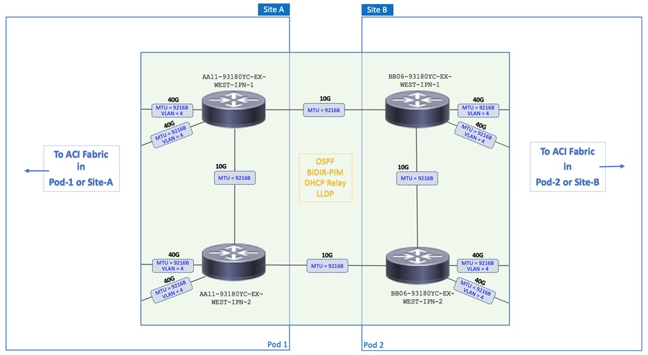
The MTU on all interfaces in the Inter-Pod network are configured for an MTU of 9216B as shown in Figure 3. The HyperFlex endpoints in the solution use jumbo frames by default for storage data and vMotion traffic. Applications endpoints hosted on the cluster may also need jumbo frame support between data centers. MTU of 9216B was chosen to maintain consistency with the default jumbo frame MTU used on several Cisco platforms. This value also takes care of the VXLAN overhead. The ACI fabric uses jumbo frames by default, so no configuration is necessary on the fabric side.
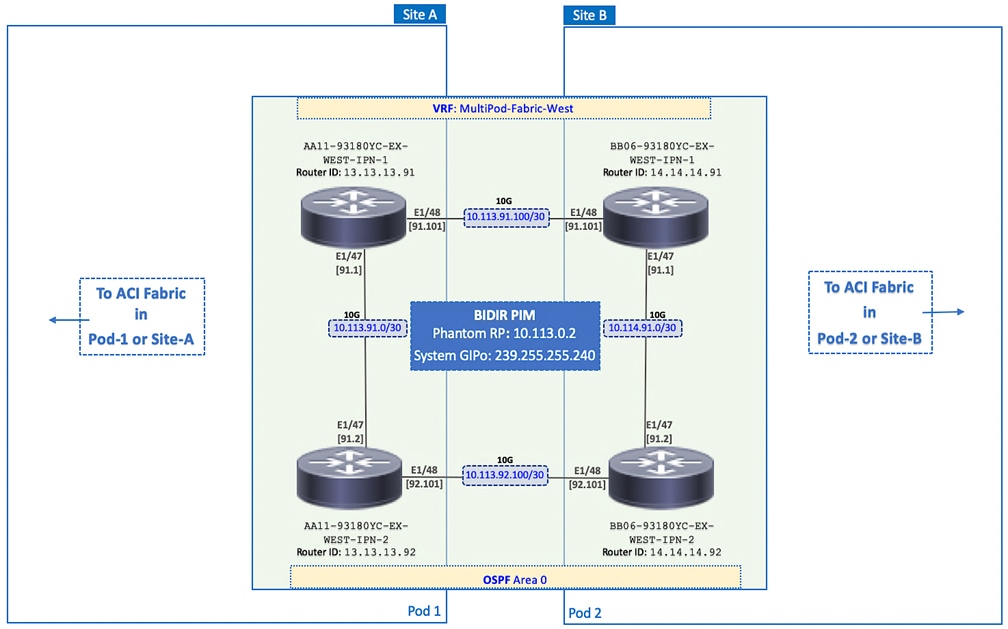
Cisco recommends isolating the Inter-Pod network using a Virtual Routing and Forwarding (VRF) instance. The VRF isolates the fabric underlay infrastructure and the Inter-Pod traffic between data centers. A dedicated VRF is used in this design as shown in Figure 4. To enable the Multi-Pod fabric, the Inter-Pod network is configured for the following protocols and features:
· OSPF is enabled on IPN devices and spine switches to exchange routing information between data centers, including VXLAN TEP addresses. All IPN devices and spine switches that connect to it are in OSPF Area 0.
· To support discovery and auto-configuration of new Pod-2 devices, including any APIC(s) deployed in Pod-1, DHCP relay is enabled on the Pod-2 IPN interfaces that connect to spine switches. This enables Pod-2 IPN devices to forward DHCP requests from new devices in Pod-2 so that they can be discovered and provisioned by active APICs in Pod-1. DHCP relay should also be enabled on IPN interfaces in Pod-1 so that Pod-2 APIC(s) can discover and provision new devices in Pod-1.
· To forward BUM traffic between Pods using IP multicast, BIDIR-PIM is enabled on all IPN devices. Each IPN forwards any BUM traffic it receives using the multicast group addresses assigned for that bridge-group. The multicast address assigned is specifically for use on the Inter-Pod network. The address is allocated from the System GIPo pool, separate from the Infra GIPo pool that is used for BUM traffic within a Pod. To provide redundancy for the Rendezvous Point (RP) in BIDIR-PIM architecture, this design also uses a Phantom RP as a backup RP.
The detailed network design and configuration parameters for the Inter-Pod network is shown in Figure 4.
Pod to IPN Connectivity
The Pod to IPN design and best-practices for connecting the ACI fabric in a Pod to the Inter-Pod network are outlined below:
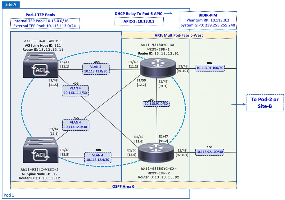
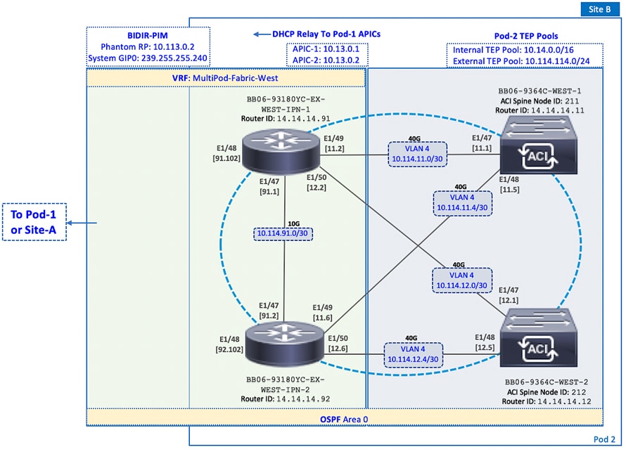
· Each Pod connects to the Inter-Pod network through one or more spine switches, but it is not necessary to connect all spine switches in a Pod to the IPN. However, at least two Spine switches from each Pod should be connected for redundancy and load distribution. IPN Traffic between Pods are distributed across all spine switches that connect to the IPN.
· As of this writing, Spine switches cannot be connected back-to-back between Pods – they must connect through at least one IPN router/switch in the Inter-Pod network. The physical links that connect spine switches to the Inter-Pod network can be 10GbE/40GbE/100GbE. On the Cisco Nexus 9364C spine switches used in this design, there are two 1/10GbE ports and additional 10GbE ports are available using special adapters on the higher speed interfaces.
· When deploying new Pods and connecting them to the ACI Multi-Pod fabric – at least one leaf should be connected to spine switches in the new Pod before it can be auto-discovered and auto-provisioned by APICs in other Pods. Spine switches must have an active link connected to a leaf switch, otherwise it cannot be added to the fabric. ACI uses LLDP to determine the presence of an active Leaf.
· Each Pod requires an External VXLAN TEP (ETEP) pool, in addition to the internal TEP pool. The internal TEP pool is used for the VXLAN overlay network within a Pod. The external TEP pool is used for VXLAN overlay network across the Inter-Pod network. Each Pod must allocate separate ETEP and internal TEP pools – they should not overlap.
In this design, redundant 40GbE links are used for connectivity from each Pod to the Inter-Pod network as shown in Figure 5 for Pod-1 and Figure 6 for Pod-2. Two spine switches connect to two IPN switches from each Pod using multiple links, resulting in multiple paths between data centers with no single point of failure. Customers can also use 10GbE links to connect spine switches to the IPN since the IPN-to-IPN links are 10GbE links in this design. However, the Nexus 9364C model of spine switch is primarily a 40/100G switch but it does have two 1/10G ports and the 40/100G ports with breakout cables could also be used as 10GbE links. It is important to note that using 10Gbps links on the Inter-Pod links when the ACI fabric is 40GbE can result in the interface and links to be over-subscribed where it transitions from 40GbE to 10GbE. In HyperFlex deployments, it is important to monitor and provide QoS if there is any congestion on these links so that storage performance is not impacted.
To enable the VXLAN overlay network and establish VXLAN tunnels between the data centers, a separate external TEP pool is assigned for use on the Inter-Pod network as shown. OSPF is enabled on the Spine switches in each Pod to connect to the IPN. To forward BUM traffic across the IPN, BIDIR-PIM is enabled on the IPN switches. Phantom RP is used to provide redundancy for the BIDIR-PIM RP. DHCP Relay is also enabled on IPN spine-facing interfaces to enable zero-touch provisioning of new switches and APICs across the Inter-Pod network. All Pod to IPN configuration is done on trunked interfaces using VLAN 4 for the encapsulation.
The detailed Pod-1 to Inter-Pod network design and configuration is shown in Figure 5.
The detailed Pod-1 to Inter-Pod network design and configuration is shown in Figure 6.
Pod to Pod Design for Seamless Connectivity between Data Centers
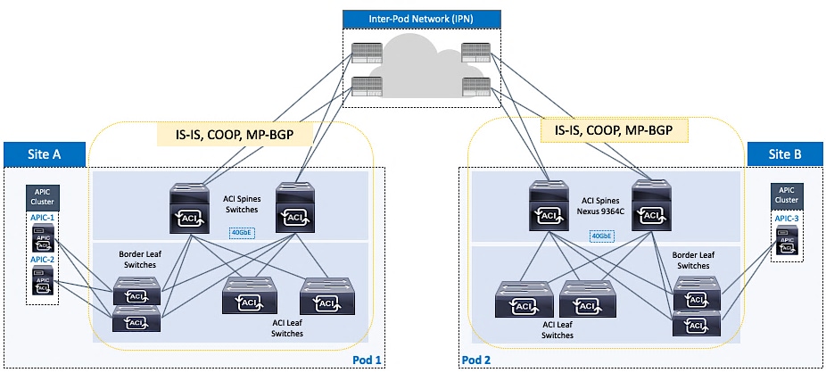
A high-level overview of the Pod to Pod design across the Inter-Pod network and the protocols that provide seamless Layer 2 extension and Layer 3 forwarding between the data centers is shown in Figure 7.
In an ACI Multi-Pod fabric, the VXLAN overlay and the IP underlay in each Pod is extended across an Inter-Pod network that is outside the ACI fabric. As stated earlier, the Inter-Pod network provides the IP underlay network for establishing VXLAN tunnels between Pods. OSPF runs on the IPN and on the spine switches in each Pod that connect to the IPN, to exchange reachability information. The external TEP addresses exchanged are then used to establish VXLAN tunnels between data centers, specifically between spine switches in each data center. Multi-protocol BGP (MP-BGP) EVPN session is also established to exchange endpoint reachability information between data centers. MP-BGP EVPN supports multiple address families (mac-address, IPv4) with multi-tenancy for exchanging Layer 2 and Layer 3 reachability information for each tenant and VRF defined in the ACI fabric. The peering will be between spine switches (that connect to IPN) in each Pod. In this design, two spine switches in each Pod connect to two spine switches in the remote data center resulting in two redundant MP-BGP EVPN sessions between data centers.
The ACI fabric within a Pod also use similar mechanisms to establish VXLAN tunnels and advertise endpoint reachability but with some notable differences. ACI uses ISIS for exchanging reachability information and COOP protocol to exchange endpoint information within each Pod. Lastly, the TEP addressing for establishing VXLAN tunnels is allocated from the internal TEP address pool for each Pod.
The detailed Pod to Pod design and configuration that enables Layer 2 extension and Layer 3 forwarding for seamless connectivity between data centers is shown in Figure 8.
High Availability
The active-active data centers enable access to critical applications and services from either data center location. To provide business continuity in the event of a site failure or a data center failure, a highly-resilient design is used throughout the ACI Multi-Pod fabric. High-availability is implemented within a Pod as well as across Pods as discussed in previous sections. Some of the high-availability provided in this design are summarized below:
· Inter-Pod Connectivity between Pods: The Inter-Pod network in this design uses two IPN routers and two Spine switches for Pod to IPN connectivity in each data center location. Each IPN router is dual-homed to the Spine switches in that location. IPN routers also connect to remote IPN routers to provide two redundant paths between the sites, with no single point of failure.
· APIC Clustering: To provide resiliency and scalability, an APIC cluster consisting of multiple nodes are used to manage an ACI Multi-Pod fabric. APIC cluster uses data sharding to maintain three copies of the fabric configuration data, one on each node in the cluster. The nodes are distributed across both Pods in this design so that each site has a local APIC available in the event of a failure in the other site.
· ACI Multi-Pod architecture: By enabling distinct fabrics to be interconnected, the architecture enables a second fabric in a second location for use as a second data center, thereby providing redundant fabrics for an active-active data center design.
· Fault Isolation: ACI Multi-Pod fabric is designed to interconnect data centers and operate as a single fabric but each Pod is also a separate failure domain. To provide fault-isolation, ACI runs separate instances of the control plane protocols (IS-IS, COOP, MP-BGP) in each Pod so that an issue in one Pod does not de-stabilize the other.
· Connectivity to Outside networks and services: To enable each site or Pod to operate as an independent data center, connectivity to outside networks is established from each Pod so that critical networks and services can be accessed directly from that data center.
· Pod Connectivity: Redundant links are used between Spine and Leaf switches and from Leaf switches to access layer devices such as Cisco UCS Fabric Interconnects in the HyperFlex UCS domains, and non-ACI routers that provide connectivity to outside networks. Virtual Port-channels (vPCs) are used between leaf switches and HyperFlex UCS domains to provide both node and link-level redundancy. APIC nodes are also dual-homed to different leaf switches to provide redundant connectivity to the fabric. Connectivity from each Pod to the IPN is through two Spines switches and use multiple links to provide both node and link-level redundancy. The connectivity within a Pod is the same for both active-active data centers.
ACI Constructs
The ACI architecture uses a number of design constructs to enable connectivity through an ACI fabric. The key design constructs are:
· Tenant – A tenant is a logical container that can represent an organization, group of applications, an actual tenant of the business or some other factor for grouping. From a policy perspective, a tenant represents a unit of isolation. All forwarding policies and configurations are part of a tenant in ACI. Within a tenant, additional ACI constructs such as VRF contexts, bridge domains, and EPGs to define policies and enable forwarding for the applications or services using the fabric.
· Virtual Routing and Forwarding (VRF) – Tenants in ACI can be further segmented into VRF instances or separate IP spaces based on the needs of the Enterprise. VRFs enable overlapping IP addressing within a given tenant. A tenant can have multiple VRFs but a VRF is associated with a single tenant. In this design, overlapping address space is not a requirement and therefore only one VRF is used for each tenant defined.
· Bridge Domain (BD) – A bridge domain is a L2 forwarding construct that represents a broadcast domain within the ACI fabric – similar to a VLAN in traditional networks. A bridge domain is associated with a single tenant VRF but a VRF can have multiple bridge domains and endpoints. The endpoints in a BD can be anywhere in the ACI fabric. It can distribute across multiple leaf switches within a Pod or across Pods. To support broadcast, multicast and unknown unicasts within the bridge domain, flooding is necessary across the fabric but ACI provides several features to minimize this flooding such as endpoint learning of addresses (Mac/IP/Both), forwarding of ARP Requests directly to a destination leaf node, maintaining a mapping database of active remote conversations, local forwarding, and probing of endpoints before they expire. Subnet(s) can be defined at the bridge-domain level to enable a L3 gateway to the BD endpoints.
· End Point Group (EPG) – An End Point Group is a collection of physical and/or virtual end points grouped together based on common factors and can be located anywhere in the ACI fabric. An EPG is associated with a single bridge domain, but a bridge domain can have multiple EPGs. Endpoints can be physical servers, virtual machines, storage arrays, switches, firewalls, or other types of devices. For example, a Management EPG could be a collection of endpoints that connect to a common segment for management.
· Application Profile (AP) – An application profile in ACI represents the requirements of an application or group of applications. An application profile can have one or more EPGs associated with it and represent the requirements of all endpoints or applications in those EPGs. A tenant can contain one or more application profiles and an application profile can contain one or more EPGs.
· Contracts – Contracts are rules and policies that define the interaction between EPGs. Contracts determine how applications use the network. Contracts are defined using provider-consumer relationships; one EPG provides a contract and another EPG consumes that contract. Contracts utilize inbound/outbound filters to limit the traffic between EPGs or applications based EtherType, IP protocols, TCP/UDP port numbers and can specify QoS and L4-L7 redirect policies.
ACI Constructs in an ACI Multi-Pod Fabric
The ACI constructs described earlier can be used to define the connectivity requirements for endpoints in an ACI fabric. Once this connectivity is defined and enabled for an endpoint group, any new endpoints added to this EPG will receive the same forwarding through the ACI fabric without the need for any additional, endpoint-specific configuration. The endpoints can be located anywhere in the fabric, including different Pods in an ACI Multi-Pod fabric.
As stated earlier, the ACI Multi-Pod fabric is a single administrative domain and therefore managed as a single ACI fabric by a single APIC cluster. As a result, the ACI constructs (Tenant, VRF, Bridge Domain, Application Profile, EPG, Contracts) and the associated policies are fabric-wide. Once an endpoint group is configured, it is available fabric-wide, enabling endpoints to be added to that EPG from anywhere in the fabric, including different Pods in an ACI Multi-Pod fabric. The endpoints in the EPG will also have seamless connectivity regardless of their location. Application workloads and other virtual machines can therefore be positioned quickly and easily from any Pod or data center by adding them to the endpoint group. The workloads can also be moved between data centers without any additional configuration.
Though the forwarding configuration for the endpoints is only done once, the access layer configuration for attaching endpoints to the fabric will need to be done for each attachment point. This is to be expected since the connectivity to the endpoints can vary depending on the type of endpoint and the access layer device and connectivity used. However, the access-layer configuration can be re-used across multiple attachment points of the same type. Access layer configuration for attaching endpoints to the fabric will be covered in greater detail later. However, it is important to note that the access-layer configuration in an ACI Multi-Pod fabric is same as that of a single-site ACI fabric.
ACI Multi-tenancy
The ACI architecture is designed for multi-tenancy. Multi-tenancy enables the administrator to partition the fabric along organizational or functional lines to form different tenants. A tenant represents a unit of isolation from a policy perspective. A tenant is a logical container for a group and their networking and security policies. All forwarding and policy configurations in ACI are done within the context of a tenant. The tenant-level constructs that define these policies in ACI include Application Profiles, EPGs, VRFs, and Bridge Domains.
Tenants can be system-defined or user-defined. System-defined tenants include mgmt, infra, and common tenants. As discussed earlier, common tenant in ACI is for shared services that are needed by multiple tenant such as Microsoft Active Directory (AD), Domain Name System (DNS), etc. Any tenant can access these services by consuming the contract provided by the common tenant for that service.
There are two user tenants defined in this design - HXV-Foundation and HXV-App-A. Administrators can define additional user tenants as needed to meet the needs of the business.
Tenant Design
The tenancy design in an Enterprise can be based on a number of factors. The tenancy design in this solution is based on the connectivity needs of the HyperFlex infrastructure and the applications hosted on the cluster. As such, two tenants are defined to meet these requirements as outlined below:
· HXV-Foundation tenant for the HyperFlex infrastructure. This tenant provides the infrastructure connectivity and services necessary to deploy and manage a HyperFlex cluster, and to access services provided by the cluster, primarily storage. This tenant can be used by any HyperFlex cluster deployed in the ACI Multi-Pod fabric. In this design, HXV-Foundation tenant provides infrastructure connectivity for both HyperFlex clusters, the optional standard cluster for Management and the stretched cluster for Applications. Customers can also choose to have multiple ‘foundation’ tenants, one for each HyperFlex cluster or based on some other criteria.
· HXV-App-A tenant for the application virtual machines hosted on the HyperFlex stretch cluster in either data center. The HyperFlex stretch cluster will need to be up and running, with compute, storage, and virtualization in place before any virtual machines can be deployed on this cluster.
This solution also uses the system-defined common tenant for accessing services outside the ACI fabric, either within the Enterprise or in the cloud. These include critical infrastructure services that are necessary for the operation of the cluster, such as the HyperFlex Witness VM and VMware vCenter.
Figure 9 provides a high-level view of the tenancy design in this solution, namely the three tenants and the associated ACI constructions for enabling forwarding through the ACI fabric.
Accessing Outside Networks and Services
Outside networks in ACI refers to any networks outside the ACI fabric and includes networks internal to the Enterprise as well as external networks. ACI provides two main options for connecting to networks and services outside the fabric as outlined below:
· Layer 2 Outside (L2Out) – for a Layer 2 bridged connection to devices outside the ACI fabric.
· Layer 3 Outside (L3Out) – for a Layer 3 routed connection to devices outside the ACI fabric.
The Layer 2 outside connection is typically used in migration scenarios for extending an existing subnet into the ACI fabric. It is also used in certain scenarios for limited access to a subnet or service from within the ACI fabric. However, to have the flexibility to route and access multiple subnets and services, either within the Enterprise or in the cloud, the preferred connectivity method is a Layer 3 outside connection. Therefore, access to outside networks in this design is through a Layer 3 outside connection.
In an active-active data center design, it is important for each data center to have independent access to outside networks so that each data center can be fully operational in the event of a failure in the other. In this design, each data center has a Layer 3 outside connection.
In this design, the L3Out connection in each active-active data center provide access to the following networks and services:
· Cloud-based services such as Cisco Intersight and Cisco Umbrella. Cisco Intersight provides centralized management of all HyperFlex and UCS clusters connected to the ACI Multi-Pod fabric, in both data center locations. Cisco Umbrella provides Enterprise users with DNS-based security when accessing the Internet or other cloud services, regardless of the location or device they use to connect.
· Infrastructure and application services such as NTP, DNS, Microsoft Active Directory, VMware vCenter and HyperFlex Witness. These services are hosted in internal Enterprise infrastructure, outside the ACI Fabric.
· Connectivity to other internal networks within the Enterprise – for example, Campus network or specific subnets such as the out-of-band management network for Cisco UCS Fabric Interconnects. To deploy the HyperFlex stretch cluster, the HyperFlex Installer hosted on the Management cluster requires access to out-of-band management network.
Shared L3Out – Design Options
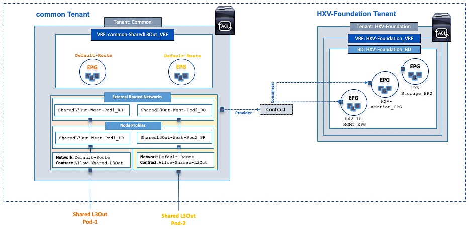
In ACI, the Layer 3 outside connection can be a shared service that is shared by multiple tenants or it can be dedicated to a single tenant. In this design, the Layer 3 outside connection is a shared service that multiple tenants can use. In ACI, the shared Layer 3 connection that multiple tenants can use (if needed) is referred to as a shared L3Out, and it is typically part of the common tenant though it can be defined in other tenants. The common tenant is a pre-defined system tenant where objects (contracts in this case) defined by this tenant are readily available to other tenants, making it easier to position common services that multiple tenants need to access. In this design, the common tenant provides a contract for accessing the shared L3Out connection that other tenants can consume to gain access to outside networks.
There are a number of design options for deploying a shared L3Out connection in the common tenant as outlined below:
· Option 1: VRF, Bridge Domain, Subnet and L3Out in system-defined common Tenant – all VRFs accessing the shared L3Out are in one tenant
· Option 2: Bridge Domain, Subnet in user-defined Tenants but VRF and L3Out in system-defined common tenant
· Option 3: VRF, Bridge Domain and Subnet in user-defined Tenants but L3Out in system-defined common tenant
Option 3 is used in this design as it is a more scalable option that also allows the tenants to maintain separate VRF instances, including overlapping address spaces. The reachability between user-defined tenants and the shared L3Out in the common Tenant is achieved using route leaking between so if there are overlapping subnets, they should not be used for accessing shared services in the common tenant.
Shared L3Out Design
The shared L3Out connections in the active-active data centers are shown in Figure 10.
To enable the L3Out connection, border leaf nodes in each Pod are connected to Layer 3 gateways in the outside network. In this design, a pair of Nexus 9000 series leaf switches are deployed as ACI border leaf switches and connected to a pair of Nexus 7000 series gateway routers. The shared L3Out design in a Pod is the same for both active-active data centers.
The detailed shared L3Out design in Pod-1 and Pod-2 are shown in Figure 11 and Figure 12.

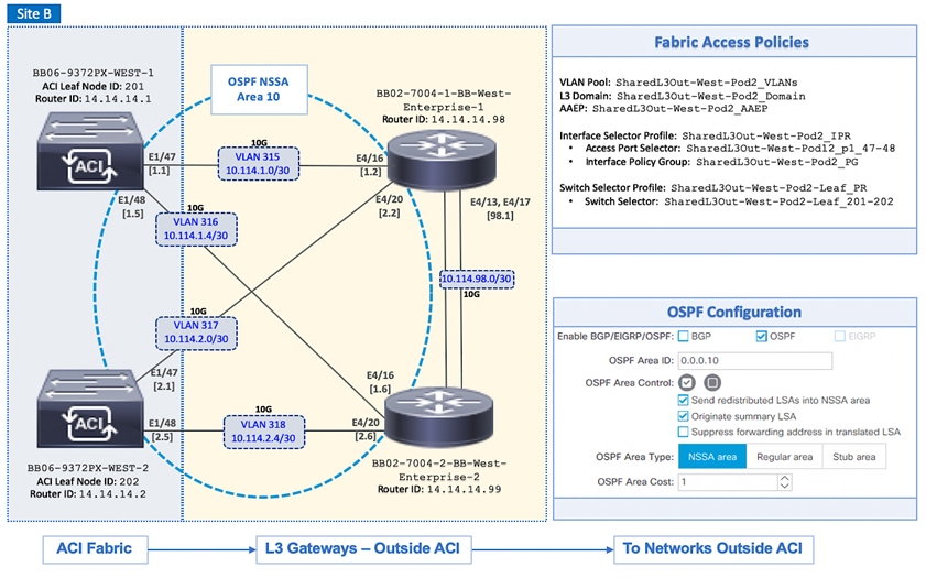
In this design, each border leaf switch is redundantly connected to Nexus 7000 gateway routers using 10GbE links. The four connections between the ACI border leaf nodes and gateway routers are Layer 3 links with a dedicated VLAN and IP subnet for each link – no link bundling is used. The border leaf switches in this design also provide connectivity to the APIC nodes in the cluster, but Cisco recommends using a dedicated pair of border leaf switches for the shared L3Out, particularly for larger deployments.
A routing protocol is then enabled across the layer 3 connection to exchange routes between the ACI fabric and the outside networks. OSPF is used in this design. Outside Routes learned by ACI in the common tenant are then shared with other ACI Tenants by providing and consuming contracts between these tenants. Similarly, ACI tenant routes in the common tenant are advertised to external gateways for reachability to ACI tenant networks. But before they can be advertised outside the fabric, these tenant routes need to be leaked into the common tenant . The leaked routes must also be unique – overlapping subnets should not be leaked.
In this design, the outside networks learned from external gateways include a default route and some internal Enterprise subnets. In the reverse direction, multiple tenant networks are advertised, typically the subnets configured at Bridge-Domain/EPG level. If needed, the tenant subnets can be further summarized depending on addressing used. All of this requires the proper contracts to be in place with Unicast routing, Shared between VRFs and Advertised Externally flags enabled.
The routes advertised for HyperFlex clusters in the ACI fabric are discussed in detail later, but it is important to note the following:
· Host routing is enabled for the HyperFlex in-band management network to advertise each node’s management IP address. The in-band management subnet is also advertised but for a HyperFlex stretch cluster with nodes in the same subnet but in different Pods or data centers, advertising just the subnet route can result in asymmetric routing and possibly loss of connectivity. Advertising host routes will ensure that all traffic to a Pod will use the dedicated Shared L3Out connection for that Pod and prevent sub-optimal routing.
· Storage-data networks for HyperFlex clusters are not advertised externally in this design. The storage-data networks are strictly Layer 2 – there is no subnet configuration and unicast routing is disabled for these networks in the ACI fabric.
The ACI constructs and design for enabling and accessing a shared L3Out service is shown in Figure 13. These include:
· Two L3Outs are defined under tenant common to connect the ACI fabric to external Cisco Nexus 7000 series gateways used in this design.
· A unique private VRF (common-SharedL3Out_VRF) network is defined under the common tenant and associated with the Default-Route EPG.
· OSPF is used for both L3Outs to provide connectivity to outside networks.
· The access layer configuration for the two shared L3Out connections in the active-active datacenters must be individually configured.
· The shared L3Out created in the common tenant is also configured to provide an external connectivity contract (Allow-Shared-L3Out) that can be consumed by any tenant. In the ACI architecture, objects (contracts in this case) in the common tenant are automatically made available to other tenants. Therefore, the shared L3Out contract will be visible to all tenants, making it easy to consume without the need for any additional configuration. If the shared L3Out is defined in any other tenant, the contract would have to be explicitly exported from that tenant to access the shared L3Out.
· When other ACI tenants consume the contract, the tenants will learn the routes to outside networks, enabling it to access outside networks and services. The outside routes in this design include a default route and some internal Enterprise networks. The tenant subnets and host routes (if enabled) shared by the tenants, will also get advertised outside the ACI fabric to enable reachability from outside the ACI fabric.
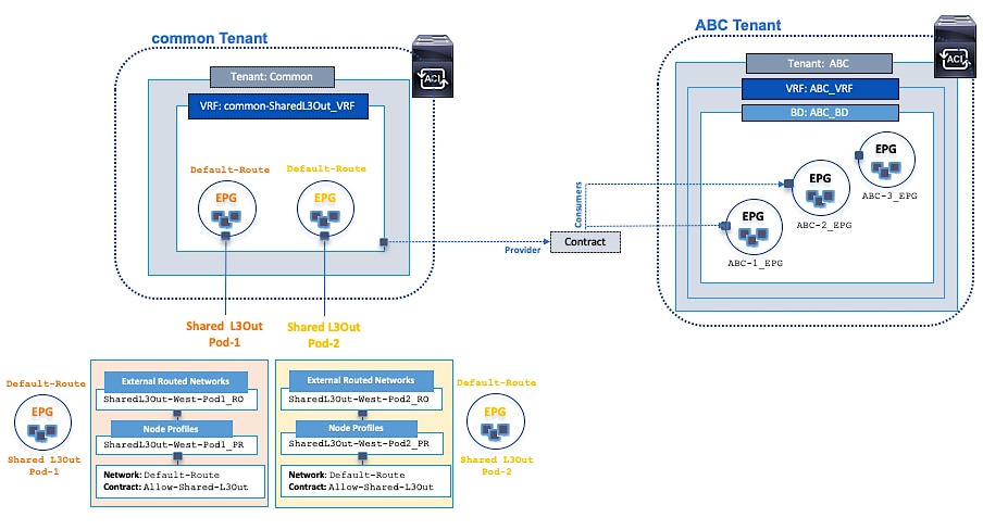
Figure 14 shows two user tenants (HXV-Foundation, HXV-App-A)and the ACI constructs for consuming the shared L3Out contract provided by the common tenant to enable access to networks and services outside the ACI fabric.
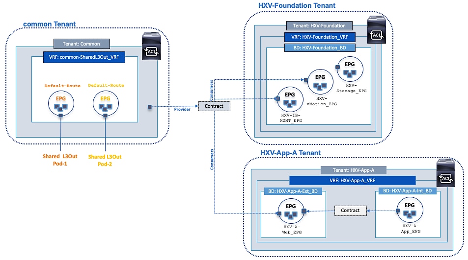
Onboarding HyperFlex Virtual Server Infrastructure
The HyperFlex Virtual Server infrastructure in this design includes an optional HyperFlex standard cluster for Management and a HyperFlex stretch cluster for Applications. Management cluster connects to Pod-1 while the Application cluster spans both Pods.
The endpoints in this design are either part of the HXV-Foundation tenant or HXV-App-A tenant and use services provided by the common tenant (for example, shared L3Out service). The infrastructure connectivity and services that HyperFlex nodes require for the operation of the cluster are provided by the HXV-Foundation tenant. Once the HyperFlex cluster is operational, the connectivity for the application virtual machines hosted on the stretched HyperFlex cluster is provided by the HXV-App-A tenant. In this design, application virtual machines are not deployed on the Management cluster, but they can be, in which case it would be part of the HXV-App-A tenant. Conversely, management virtual machines are not deployed on the Application cluster, but it can be, and it would be part of the HXV-Foundation tenant.
The infrastructure connectivity and services provided by the HXV-Foundation tenant in the ACI fabric are:
· Connectivity to in-band management network: The HyperFlex ESXi hosts and the storage controller virtual machine (SCVM) on every HyperFlex node communicate over the same in-band management network in the HyperFlex architecture. In this design, both clusters share the same in-band management network. Customers can also use dedicated in-band management EPGs for each cluster. The management network and the connectivity between these end points are enabled in the ACI fabric by the in-band EPG.
· Connectivity to storage-data network: The HyperFlex ESXi hosts and the storage controller virtual machine on every HyperFlex node also communicate across the storage-data network to provide storage services in the HyperFlex architecture. The communication between nodes on network is critical for the health of the cluster, for providing storage services and for the basic functioning of the distributed storage cluster. Since the health of the storage cluster and the integrity of the data relies on this network connectivity between the nodes, a separate storage-data network is used for each cluster in order to isolate this network. The storage-data network and the connectivity between these end points are enabled in the ACI fabric by the storage-data EPG.
· Connectivity to VMware vMotion network: To support VMware vMotion for the virtual machines hosted on the HyperFlex ESXi cluster, the hosts needs connectivity to a VMware vMotion network. In this design, both clusters share the same VMware vMotion network. The vMotion network and the connectivity between ESXi hosts in the cluster are enabled in the ACI fabric by the vMotion EPG.
· Connectivity for infrastructure management and services network (optional): Additional networks and EPGs can be defined in this tenant to provide infrastructure management services or to host operational tools for managing the HyperFlex Virtual Server Infrastructure. In this design, the HyperFlex installer VM is an example of a service hosted on this network. The Installer VM is used for deploying the HyperFlex stretch cluster and requires connectivity to multiple networks and endpoints to do this. The EPG for this network will be configured to enable the necessary connectivity.
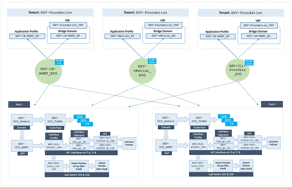
In the ACI architecture, ACI constructs (Tenants, Application profiles, Bridge domains, EPGs etc) define and enable the connectivity through the fabric. To meet the infrastructure connectivity requirements outlined above, EPGs and other ACI constructs are defined in the HXV-Foundation tenant to enable this connectivity. The VLAN networks that HyperFlex endpoints use for communication in the UCS fabric, are then mapped to end-point groups in ACI to enable forwarding between endpoints in the same network and to other networks – for example, to outside networks through the shared L3Out in common tenant.
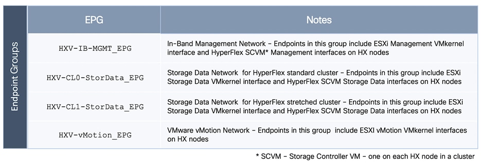
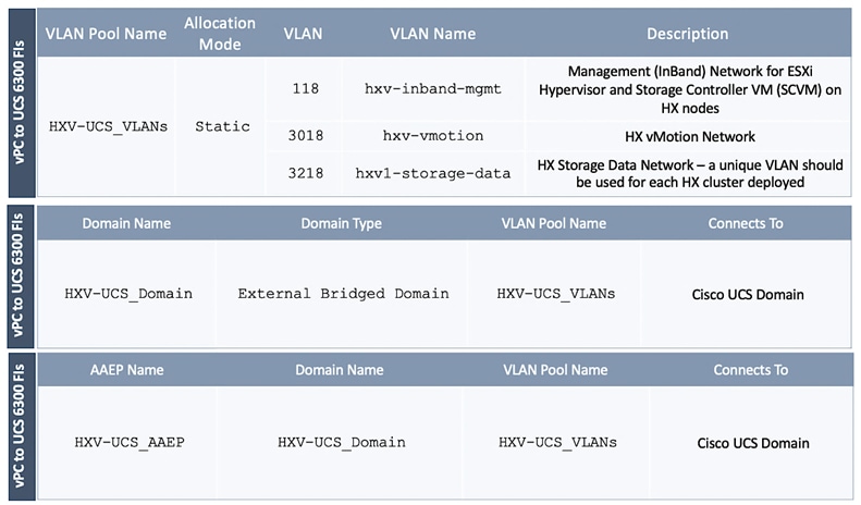
The EPGs used in this design to enable infrastructure connectivity for HyperFlex clusters are listed in Figure 15.
The ACI constructs associated with the above EPGs are provided in Figure 16 and Figure 17.
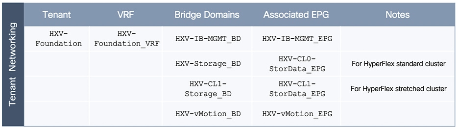
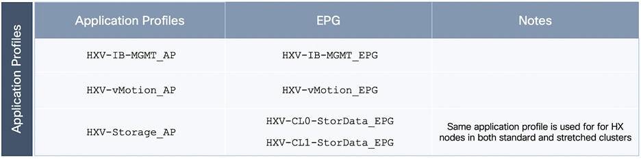
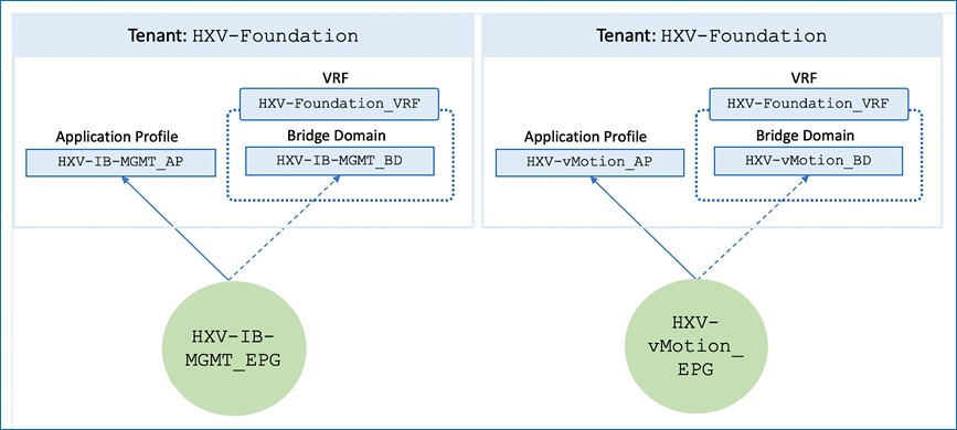
The relationship between the various ACI constructs that enable connectivity for the HyperFlex infrastructure in this design are shown in Figure 18 and Figure 19.
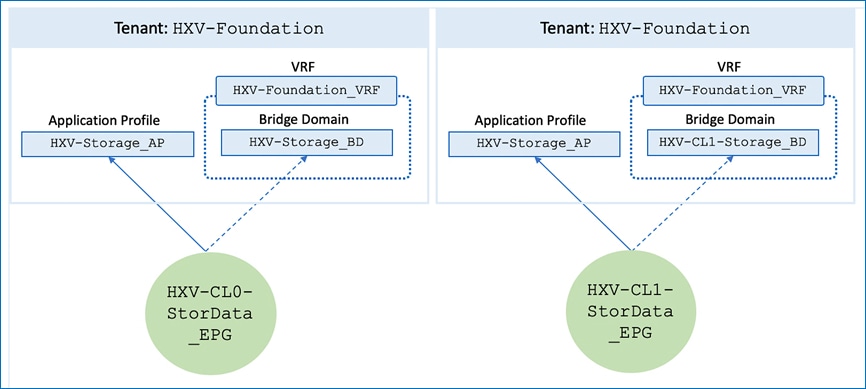
Note that a dedicated storage-data network is used for each HyperFlex cluster (Management, Applications) in this design.
Access to Outside Networks and Services
To enable access to outside networks and services, HyperFlex endpoints in HXV-Foundation tenant needs to consume the shared L3Out contract provided by the common tenant. In this design, HyperFlex endpoints (ESXi nodes, SCVM) in the management network and vMotion networks have connectivity to the outside networks. However, the same endpoints on the storage data network are not allowed to (and cannot be since it is not enabled for L3 forwarding). The storage-data network should be isolated as much as possible and should not require connectivity outside the network.
Figure 20 shows the ACI fabric connectivity in this design for accessing networks and services using the shared L3Out. This connectivity is available to in-band and vMotion EPGs in HXV-Foundation tenant that have consumed the shared L3Out contract.
The consumed contract enables access to outside networks from both active-active data centers. HyperFlex endpoints in all Pods will leverage the above access but will use the local connection to reach the outside networks. Routing will direct the outbound traffic via the shortest and therefore the local Shared L3Out.
Access Layer Connectivity to UCS Domain for HyperFlex Clusters
Before any virtual server infrastructure can be deployed in the active-active datacenters, the ACI Multi-Pod fabric must provide access layer connectivity to the UCS domains and HyperFlex servers that provide the compute, storage, and server networking infrastructure for each data center. The access layer connectivity includes:
· Physical connectivity to the UCS domains that HyperFlex clusters connect to. A Cisco UCS domain consists of a pair of Cisco UCS Fabric Interconnects with HyperFlex servers dual-homed to both Fabric Interconnects. The fabric interconnects have uplinks that connect to Leaf switches in the ACI fabric.
· Access Layer configuration and setup to enable connectivity to and from the Fabric Interconnects and HyperFlex clusters in the UCS domain.
The access layer connectivity provided for HyperFlex clusters and UCS domains in an ACI Multi-Pod fabric is the same as that of a single site ACI fabric. The only difference here is that they could be connected to any Pod. The ACI fabric policies are re-used for all UCS domains to the extent possible in this design.
Physical Connectivity to UCS Domains for HyperFlex Clusters
The physical connectivity to the UCS domains for the HyperFlex stretched cluster is shown in Figure 21 and Figure 22.
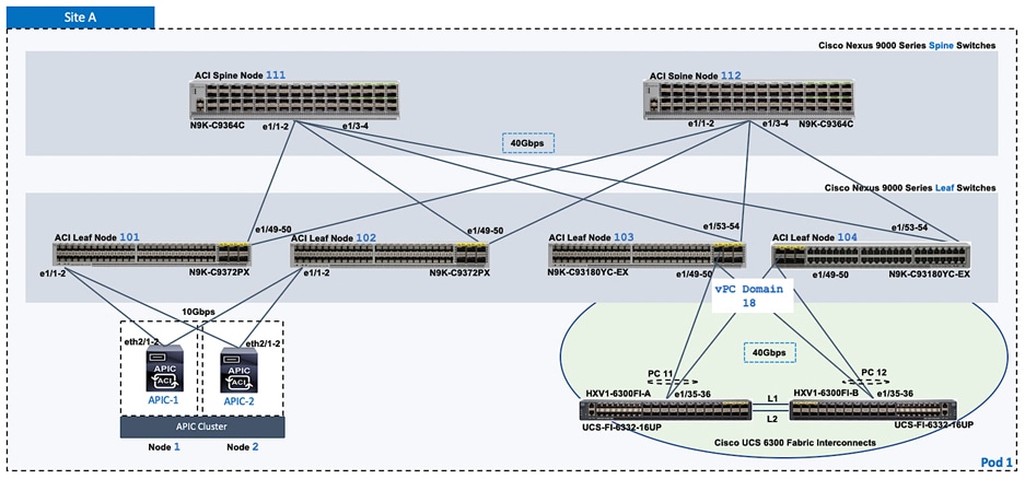
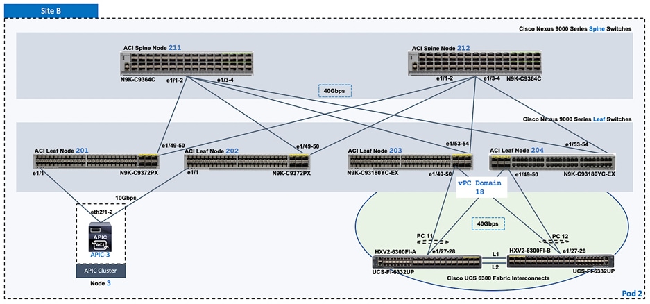
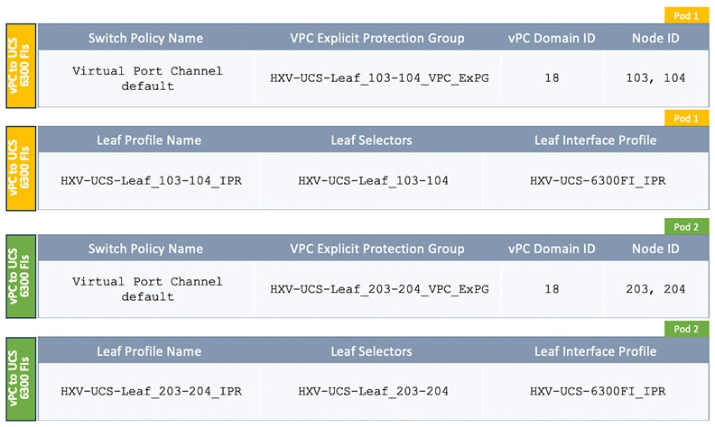
For the HyperFlex stretched cluster (Application cluster), a pair of Cisco UCS 6300 Series Fabric Interconnects are connected using 40Gbps links to a pair of Leaf switches in each Pod. In each Pod, two virtual Port Channels (vPCs) will be established from the Leaf switches to each Cisco UCS Fabric Interconnect (FI-A, FI-B). The vPC will enable link bundling to enable higher aggregate bandwidth and availability between the ACI fabric and UCS domains.
For the HyperFlex standard cluster (Management cluster), connectivity similar to the one used for the stretched cluster is used. The HyperFlex standard cluster connects to a pair of Cisco 6200 Fabric Interconnects in Pod-1 and use 10GbE for the vPC links between the ACI leaf switches and Cisco UCS Fabric Interconnects.
Access Layer Configuration - To Cisco UCS Domain for HyperFlex Clusters
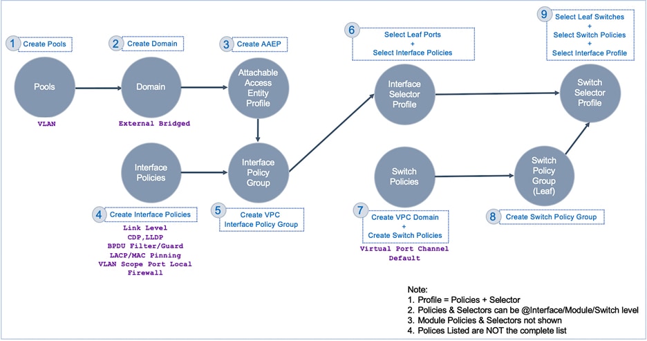
In ACI, fabric access policies represent the access layer design and configuration for connecting to access layer devices. The workflow for connecting access layer devices to the ACI fabric involves defining policies and then applying the policies to the leaf switch interfaces that connect to the access layer devices. A high-level workflow of the fabric access policies for connecting to the Cisco UCS Fabric Interconnects in this design is shown in Figure 23. The policies will configure the access ports on the leaf switches and create vPCs from a leaf switch pair to the Cisco UCS Fabric Interconnects in each data center.
The detailed fabric access polices that enable access layer connectivity to the HyperFlex UCS domains in the active-active data centers are provided below.
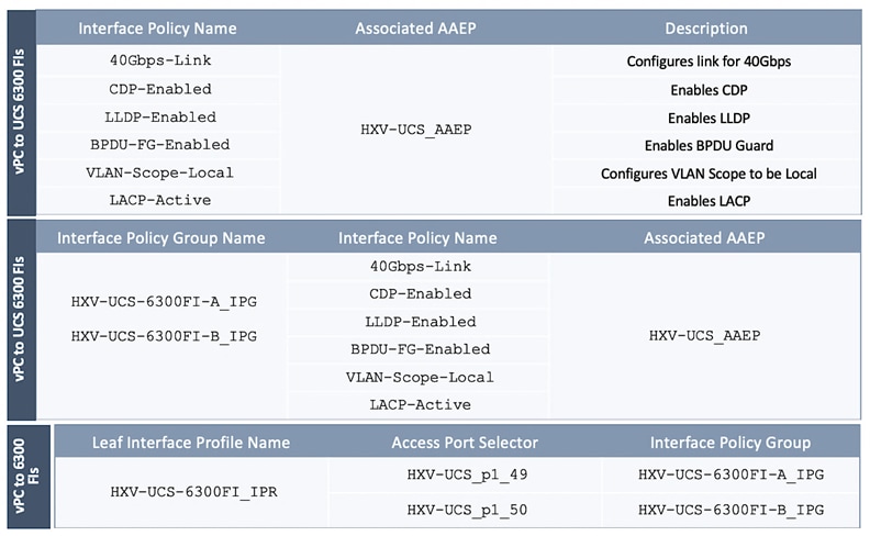
When a HyperFlex infrastructure EPG is deployed on the access layer connection to the UCS domains, it establishes the following mapping or relationship between the fabric access policies and the EPG as shown in Figure 27.
Note that these policies are re-used or leveraged for both UCS domains in the HyperFlex stretch cluster. A similar set of fabric access policies are used for the access layer connectivity to the UCS domain for the HyperFlex standard cluster (Management). The individual policies are re-used across all UCS domains whenever possible.
Integration with Virtual Machine Manager
The Virtual Machine Manager (VMM) integration in ACI enables the Cisco APIC to manage the virtual switching on ESXi hosts. When EPGs are created in the ACI fabric, APIC will dynamically allocate a VLAN for the new EPG and create a corresponding port-group in the VMM domain. With the virtual switching in place, application virtual machines can now be deployed and added to the port-group.
The APIC can integrate with VMware vCenter to manage a VMware vSphere Distributed Switch (vDS) or a Cisco ACI Virtual Edge (AVE). This design uses an APIC-controlled VMware vDS on both (Applications and Management) HyperFlex clusters. However, the infrastructure VLANs in both clusters will remain on the VMware vSwitch that was created by the HyperFlex installer. The installation process also creates VM network VLANs but these VLANs will be migrated to VMware vDS in this design. Customers can also use Cisco AVE for the VM network VLANs.
For VMM integration to work correctly, the following configuration should be in place:
· Uplinks on the ESXi hosts must be configured to use either CDP or LLDP; only one can be enabled at a time; LLDP is used in this design. CDP is the default configuration setup by the HyperFlex installer, but this can be changed to LLDP through the UCS manager.
· VLAN pool for the VM networks must be pre-allocated in the ACI fabric
· VLAN pool, corresponding to the pool created in the ACI fabric, must be enabled on the server’s virtual NIC for VM networks and on the Fabric Interconnect uplinks connecting to the leaf switches.
During the installation stage, HyperFlex Installer can configure the VM Network VLAN pool on the Fabric Interconnects and HyperFlex servers. It can also be created using the HyperFlex post-install script or it can be added using a Cisco UCS manager.
Onboarding Applications
Once the infrastructure and virtualization setup for hosting Applications is complete, applications can be deployed on the Application HyperFlex cluster in either datacenter.
Figure 28 shows the ACI constructs used to onboard a sample two-tier application in this design.
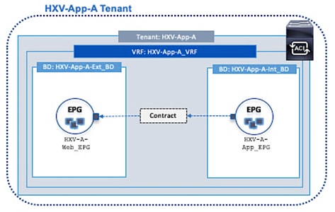
To enable access to outside networks and services, the shared L3Out contract provided by the common tenant is consumed by the Application tenant as shown in Figure 29.
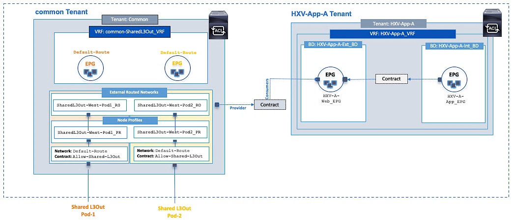
Virtual Server Infrastructure Design
Two HyperFlex clusters provide the hyperconverged virtual server infrastructure in this design – one to host Management virtual machines (optional) and another for Application workloads. The HyperFlex clusters and UCS domains attached to the ACI Multi-Pod fabric are locally managed from within the Enterprise and also centrally managed from the cloud using Cisco Intersight.
Management HyperFlex Cluster
The Management HyperFlex cluster is optional in this design as the services hosted on this cluster can be provided from a customer’s existing infrastructure, either from within the fabric or outside the ACI fabric. In this design, the Management cluster serves as a dedicated cluster for hosting monitoring and other operational tools directly from within the ACI fabric.
Critical Infrastructure and management services for operating the HyperFlex clusters are hosted outside the ACI fabric in this design. ACI provides access to these services using a shared L3Out connection in each data center location. A 4-node HyperFlex standard cluster is used for the Management HyperFlex cluster as shown in Figure 30. This cluster is connected to Pod-1 and uses dedicated leaf switches for connecting to the ACI fabric.
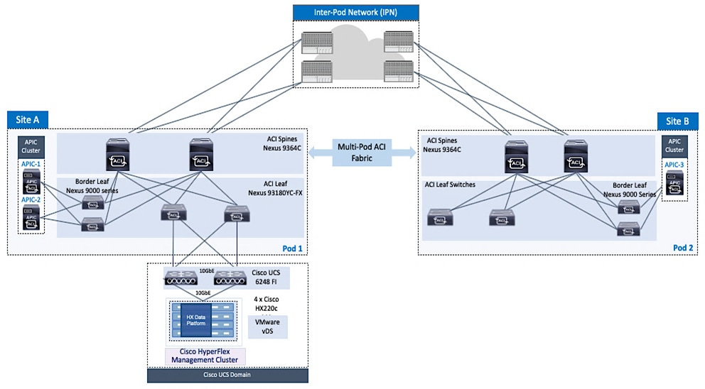
The Management cluster is deployed from the cloud using Cisco Intersight. The HyperFlex nodes in the management cluster and the virtual machines hosted on the cluster can access networks and services outside the ACI fabric using the shared L3Out connection in Pod-1.
Application HyperFlex Cluster
The Application HyperFlex cluster in this design spans both data centers, enabling application virtual machines to be deployed in either data center with seamless connectivity and mobility as needed. A 4+4 node HyperFlex stretched cluster is used for the Application cluster. The nodes in the stretched cluster are evenly distributed between Pod-1 and Pod-2 and provides the virtual server infrastructure for the two active-active data centers as shown in Figure 31.
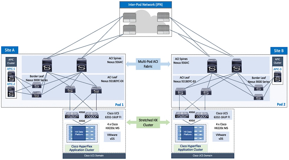
The stretched cluster is deployed using a HyperFlex Installer VM hosted on the Management HyperFlex cluster. The HyperFlex nodes in the application cluster on Pod-1 and the application virtual machines hosted on it can access networks and services outside the ACI fabric using a shared L3Out connection in Pod-1. Similarly, HyperFlex nodes in the application cluster on Pod-2 and the application virtual machines hosted on it can access networks and services outside the ACI fabric using the shared L3Out connection in Pod-2.
Cisco UCS Networking for HyperFlex Infrastructure
The HyperFlex clusters in this design use dedicated UCS domains to connect the nodes in the cluster and to connect to the ACI fabric. A UCS domain consists of a pair of Cisco UCS 6x00 series Fabric Interconnects (FI) and the servers that connect to it. A single Cisco UCS domain can support multiple HyperFlex clusters, the exact number depends on the size of the cluster and the port-density on the Fabric Interconnect model chosen. However, in this design, the Management and the Application clusters connect to different UCS domains, and the Application cluster uses two UCS domains since it is a HyperFlex stretched cluster with nodes in two different data centers. Cisco UCS manager that manages the UCS domain, runs on the Fabric Interconnects. In this design, the HyperFlex clusters and the corresponding UCS domains are managed locally using Cisco UCS Manager and HyperFlex Connect, and also from the cloud using Cisco Intersight. Cisco Intersight offers centralized management of all Cisco UCS and HyperFlex infrastructure in the Enterprise.
Unified Fabric – Cisco UCS Fabric Interconnects
Cisco UCS Fabric Interconnects are an integral part of the HyperFlex system. The fabric interconnects provide a unified fabric with integrated LAN, SAN, and management connectivity for all HyperFlex servers that connect to it. It also provides a lossless and deterministic switching fabric, capable of handling I/O traffic from hundreds of servers.
Cisco UCS Fabric Interconnects are typically deployed in pairs, each providing a separate switching fabric -referred to as Fabric A or FI-A and Fabric B or FI-B. Cisco UCS Manager that manages the UCS domain runs on the Fabric Interconnects. From a management perspective, one FI is the primary, and the other is the secondary. Each FI has its own IP address and a third roaming IP that serves as the cluster IP for management. However, both fabric interconnects are active from a forwarding perspective, and provide redundancy for the fabric in the event of a failure.
Every node in a HyperFlex cluster connects to a pair of Fabric Interconnects in the UCS domain, which in turn connects to the ACI fabric. The uplink speeds to the ACI fabric and downstream to the HyperFlex servers will depend on the Fabric Interconnect model used. Though all Fabric Interconnect models are supported, the two Fabric Interconnect models used in this design are:
· Cisco UCS 6200 series fabric interconnects provide a 10GbE unified fabric with 10GbE uplinks for northbound connectivity to the ACI fabric and 10GbE downlinks for southbound connectivity to HyperFlex servers in the Management cluster.
· Cisco UCS 6300 series fabric interconnects provide a 40GbE unified fabric with 40GbE uplinks for northbound connectivity to the ACI fabric and 40GbE downlinks for southbound connectivity to HyperFlex servers in the Application cluster. Since the cluster is a stretched cluster, the nodes are distributed across two pairs of UCS 6300 fabric interconnects and connect to two separate ACI fabrics in this solution.
Uplink Connectivity to Data Center Network Fabric
The HyperFlex UCS domains connect to Nexus 9000 series leaf switches in the ACI fabric for northbound connectivity to other parts of the Enterprise, and for intra-cluster connectivity. As stated previously, multiple UCS domains are used in this design to support the Management and Applications cluster.
For higher bandwidth and resiliency, multiple links (10GbE/40GbE) are used for uplink connectivity to the ACI fabric. Cisco UCS FI and Nexus switches support 802.3ad standards for aggregating links into a port-channel (PC) using Link Aggregation Protocol (LACP). Multiple links on each FI are bundled together in a port-channel and connected to upstream Nexus switches in the ACI fabric. The uplinks from each FI connect to different leaf switches in a leaf switch pair. The leaf switches in the leaf switch pair use a virtual Port-channel (vPC) configuration to bundle the links to each FI. vPC enables links from two different switches to be bundled such that it appears as a “single logical" port channel to a third device (in this case, FI). This PC/vPC based design provides link and node-level redundancy and higher aggregate bandwidth for LAN, SAN, and Management traffic to/from the UCS domain.
The UCS uplinks operate as trunks, carrying traffic from multiple 802.1Q VLAN IDs to the ACI fabric. It is important to note that this can also include traffic between HyperFlex servers in the same UCS domain. Under certain failure scenarios such as a server uplink failure, traffic can failover to a backup fabric, resulting in traffic that normally does not leave the Cisco UCS domain to now be forwarded over the Cisco UCS uplinks to the ACI fabric for intra-domain forwarding or forwarding between fabric interconnects in the same UCS domain.
UCS Networking Design for Application Cluster
The Application cluster consists of 4+4 node HyperFlex stretch cluster that connects to the ACI fabric in each Pod through a pair of Cisco UCS 6332 Fabric Interconnects. The stretched cluster connectivity to the ACI fabric in Pod-1 and Pod-2 are shown in Figure 32 and Figure 33.


The Cisco UCS 6300 Fabric Interconnects connect to a pair of upstream Nexus 9000 series leaf switches using the following links:
· 2 x 40GbE links from FI-A to Nexus leaf switches, one to each Leaf switch
· 2 x 40GbE links from FI-B to Nexus leaf switches, one to each Leaf switch
The FI side links are bundled using a port-channel, while the links on the Nexus 9000 leaf switch pair are bundled using a virtual port-channel. The link bundling provides each UCS domain with160Gbps (40Gbps per link x 2 uplinks per FI x 2 FI) of uplink bandwidth to/from the ACI fabric. Additional links can be added as needed to increase the uplink bandwidths.
The uplinks carry HyperFlex VLANs for in-band management, vMotion, storage data and VM networks. The VLANs are also enabled on the individual vNIC templates going to each server in the HX cluster.
Each server in the HyperFlex stretch cluster uses a VIC 1387 adapter with two 40Gbps uplink ports to connect to each FI, resulting in two redundant paths, one through each fabric (FI-A, FI-B). The two uplinks provide each server with 2x40Gbps of uplink bandwidth and redundancy in the event of a failure.
UCS Networking Design for Management Cluster
The Management cluster consists of 4-node HyperFlex standard cluster that connects to the ACI fabric in Pod-1 through a pair of Cisco UCS 6200 series Fabric Interconnects as shown in Figure 34.
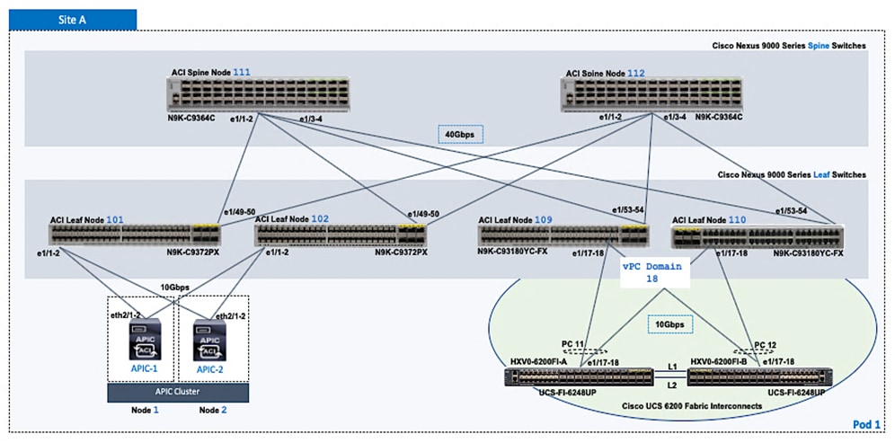 The FI side ports are configured to be a port-channel, with vPC configuration on the Nexus leaf switches. The above connectivity provides the UCS domain with 40Gbps (10Gbps per link x 2 uplinks per FI x 2 FI) of uplink bandwidth to/from the ACI fabric. The uplink bandwidth can be increased as needed by adding additional links. Each server in the cluster uses two 10Gbps uplink ports to connect to each FI. The two uplink ports are bundled in a port-channel to provide 2x10Gbps of uplink bandwidth from each server.
The HyperFlex VLANs for in-band management, vMotion, storage data and VM network vlans are enabled on the FI uplinks. The VLANs are also enabled on the individual vNIC templates going to each server in the HX cluster.
Cisco UCS Connectivity for HyperFlex Installation
To deploy a HyperFlex cluster, the HyperFlex installer (HyperFlex Installer VM or Cisco Intersight) requires the connectivity to the following components in the UCS domain:
· Connectivity to the management IP address of Fabric Interconnects in the UCS domain(s). In this design, the fabric interconnects in both Pods are part of an out-of-band management.
· Connectivity to the external management IP addresses of servers in the HyperFlex cluster. This IP address comes from an KVM IP Pool (ext-mgmt) in the service profile template used to configure HyperFlex servers. In this design, these IP addresses are also reachable through the out-of-band management network.
In this design, Cisco Intersight that was used to deploy the Management HyperFlex cluster did not rely on the ACI Multi-Pod fabric for connectivity. However, the connectivity from the HyperFlex installer for the HyperFlex stretched cluster and the out-of-band management network was through the ACI Multi-Pod fabric. Cisco Intersight currently does not support the deployment of Cisco HyperFlex stretch clusters. Cisco Intersight is however used for centrally managing and monitoring all clusters in the solution as it brings a number of key operational capabilities to the solution. The connectivity from deployed clusters to Cisco Intersight is also enabled by the ACI Multi-Pod fabric, specifically the Shared L3Out in each Pod.
Cisco HyperFlex Infrastructure Connectivity
Infrastructure connectivity is critical to the health and operation of a cluster. HyperFlex infrastructure requires multiple networks and VLANs/subnets to provide connectivity between nodes in the cluster. The nodes can be in different sites as is the case for the HyperFlex stretch cluster used in this solution. Connectivity is also required between storage controller VMs that enable the distributed, hyperconverged storage provided by the cluster. In a HyperFlex stretched cluster, the networking in the two halves of the cluster are identical.
HyperFlex VLANs and Subnets
The infrastructure connectivity required for a HyperFlex cluster can be categorized as follows:
· Management: A HyperFlex cluster requires management connectivity to manage the ESXi hosts and the storage controller virtual machines (SCVM) in the cluster. The management interfaces in a HyperFlex cluster include SCVM Management Interfaces, SCVM Replication Interfaces on each node, and a Roaming HX Cluster Management IP (one per cluster).
· Storage: A HyperFlex cluster requires network connectivity to manage the storage sub-system in a given HyperFlex cluster. These connections are used by the Cisco Data Platform software (HXDP) to manage the HyperFlex Distributed File System. The storage interfaces in a HyperFlex cluster include SCVM Storage Interface, Roaming HX Cluster Storage IP (one per cluster) and VMkernel interface for storage access on each ESXi host in the cluster.
· vMotion: To enable vMotion for guest VMs on ESXi hosts in the cluster, a vMotion network is needed for connectivity between ESXi hosts in the cluster. Each host in the cluster also requires a VMkernel interface.
· Virtual Machines: A HyperFlex cluster will need to provide connectivity to the guest virtual machines deployed on hosts in the cluster so that they can be accessed by other VMs and users in the organization.
The HyperFlex infrastructure networks for Management, Storage and vMotion are shown in Figure 35.
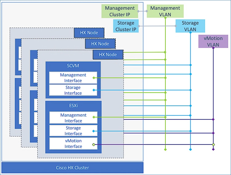
HyperFlex Networking Guidelines and Best Practices
Design best practices and other guidelines for HyperFlex infrastructure connectivity are provided below:
· The HyperFlex storage-data network should be on a dedicated, isolated network, preferably Layer 2 and should not be used for other traffic. In this design, each cluster has a dedicated storage-data network.
· In this design, the HyperFlex management and vMotion networks are shared by the two clusters in the solution. Customers can choose to do the same or use a dedicated network for each cluster.
· HyperFlex uses jumbo frames for storage and vMotion traffic and it is configured in the UCS domain(s) by the automated install process. However, jumbo frames should also be enabled end-to-end, across the network fabric to prevent service interruptions. Jumbo frames enable IP traffic to use a Maximum Transmission Unit (MTU) size of 9000 bytes. Larger MTU value enables each IP packet to carry a larger payload, therefore transmitting more data per packet, and consequently sending and receiving data faster. By default, ACI fabrics uses jumbo MTUs on all edge and core facing interfaces. However, the Inter-Pod network that connects the Pods in an ACI Multi-Pod fabric may need to be manually configured.
· The HyperFlex installer requires reachability to the different components to install, configure and deploy the cluster. In the UCS domain, it requires connectivity to the management cluster IP for the Fabric Interconnects and the external management (ext-mgmt) IP addresses of the UCS servers (HyperFlex nodes). It also requires connectivity to VMware vCenter to configure vSphere policies for the cluster.
· Replication Networking is setup after the initial install by the installer or Cisco Intersight. Replication was not validated in this design. For a detailed discussion on HyperFlex Replication – see the Cisco HyperFlex 3.0 for Virtual Server Infrastructure with VMware ESXi design guide listed in the References section.
Validated Design – HyperFlex VLANs and Subnets
The infrastructure and VM networks, and the VLANs used for the HyperFlex stretched and standard clusters in this design are shown in Figure 36. During the install of the cluster, for each network type listed, HyperFlex will create a VMware virtual switch (vSwitch) on each ESXi host in the HyperFlex cluster. The installer will also provision the virtual switches with port-groups for each of the VLANs listed. These VLANs are also configured in the Cisco UCS Fabric Interconnects on its two uplinks to the ACI fabric and on the vNICs to the HyperFlex nodes.
If replication is enabled (to a second cluster), a VLAN will need to be allocated for this. The replication VLAN will map to a port-group on the inband management vSwitch. Replication networking is not part of the initial automated install of the HX cluster. Replication was not validated in this design.
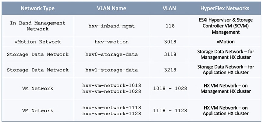
The HyperFlex Installer can also pre-provision VM Network VLAN pool to create VLANs in the Cisco UCS Fabric, a VMware vSwitch for VM network traffic and port-groups for the pool. Customers can also provision these VLANs later, but it would need to be manually configured through UCS Manager and VMware vCenter. In this design, the VM network VLANs are initially mapped to port-groups on a VMware virtual switch and then migrated to an APIC-controlled VMware virtual distributed switch (vDS) (or Cisco ACI Virtual Edge) after the initial install.
Virtual Networking Design
The HyperFlex installer (Installer VM or Cisco Intersight) deploys the Cisco HyperFlex system with a pre-defined virtual networking design on the ESXi hosts in the cluster. The virtual networking for a HyperFlex stretched cluster is identical for all hosts in the cluster regardless of their location. The design separates the different traffic types using VMware virtual switches (vSwitch). During the install of the cluster, four virtual switches are created with two uplinks per vSwitch – the uplinks at the hypervisor level are referred to as virtual NICs (vNICs). The vNICs are created on the Cisco UCS VIC adapter in each server using Cisco UCS service-profiles.
The default virtual Switches created by the automated install process are:
vswitch-hx-inband-mgmt: This is the default ESXi vSwitch0 that is renamed by the ESXi kickstart file as part of the automated installation process. The switch has two uplinks, active on fabric A and standby on fabric B – by default, jumbo frames are not enabled on these uplinks. The following port groups are created on this vSwitch:
· Port group for the standard ESXi Management Network. The default ESXi VMkernel port: vmk0, is configured as a part of this group on each ESXi HyperFlex node.
· Port Group for the HyperFlex Storage Platform Controller Management Network. The SCVM management interfaces is configured as a part of this group on each HyperFlex node.
· If replication is enabled across two HyperFlex clusters, a third port group should be deployed for VM snapshot replication traffic.
The VLANs associated with the above port-groups are all tagged VLANs (not native VLANs) in Cisco UCS vNIC templates. Therefore, these VLANs are also explicitly configured in ESXi/vSphere.
vswitch-hx-storage-data: This vSwitch has two uplinks, active on fabric B and standby on fabric A – by default, jumbo frames are enabled on these uplinks. The following port groups are created on this vSwitch:
· Port group for the ESXi Storage Data Network. The ESXi VMkernel port:vmk1 is configured as a part of this group on each HyperFlex node.
· Port group for the Storage Platform Controller VMs. The SCVM storage interfaces is configured as a part of this group on each HyperFlex node.
The VLANs associated with the above port-groups are all tagged VLANs (not native VLANs) in Cisco UCS vNIC templates. Therefore, the VLANs are also explicitly configured in ESXi/vSphere.
vswitch-hx-vm-network: This vSwitch has two uplinks, active on both fabrics A and B – by default, jumbo frames are not enabled on these uplinks. However, in this design, it has been reconfigured for jumbo frames through Cisco UCS Manager. The VLANs associated with the above port-groups are all tagged VLANs (not native VLANs) in Cisco UCS vNIC templates. Therefore, these VLANs are also explicitly configured in ESXi/vSphere.
vmotion: This vSwitch has two uplinks, active on fabric A and standby on fabric B – by default, jumbo frames are enabled on these uplinks. The IP addresses of the VMkernel ports (vmk2) are configured by using post_install script. The VLANs associated with the above port-groups are all tagged VLANs (not native VLANs) in Cisco UCS vNIC templates. Therefore, these VLANs are also explicitly configured in ESXi/vSphere.
Once the cluster is operational, additional virtual machine networks may need to be added to roll out new applications and services. This requires the VLANs to be provisioned in the ACI fabric, on the Fabric Interconnects and on the ESXi hosts in the cluster through Cisco APIC, Cisco UCS Manager and VMware vCenter respectively. To minimize some of the provisioning, ACI provides VMM integration with VMware vCenter. As new applications and services are deployed on the ACI side, APIC will leverage this integration to dynamically allocate a VLAN for use by new application or service outside the ACI fabric and provision the corresponding virtual-networking through vCenter. To enable this dynamic provisioning, APIC will need to manage the virtual switching – using either a VMware virtual distributed switch (vDS) or Cisco ACI Virtual Edge (AVE). APIC will also require a pre-defined pool to allocate VLANs from.
Virtual Switching Options
A summary of the virtual switching options available on the solution are:
· VMware vSphere vSwitch is used for critical infrastructure and management services as outlined earlier. This includes in-band management (vswitch-hx-inband-mgmt), storage data (vswitch-hx-storage-data) and VM migration (vmotion) networks.
· APIC-controlled VMware vDS is used in the Management and Applications clusters. This includes networks for the HyperFlex Installer VM, and monitoring tools hosted on the Management cluster. In this design, the services hosted on the Management HyperFlex cluster are used to deploy other stretch clusters in the ACI fabric, and to manage the end-to-end solution. VMware vDS is also used in the HyperFlex stretch cluster for the Applications VMs hosted on the cluster. The default VM network and vSwitch (hx-vm-network) created by the automated installer process for the Management and Applications cluster will be deleted to migrate the uplinks to the APIC-controlled vDS.
· (Optional) APIC-controlled Cisco AVE could also be used instead of VMware vDS. In the previous release of this solution, Cisco AVE was used for the application VM networks on the stretched HyperFlex cluster.
Virtual Switching using Cisco ACI Virtual Edge
Cisco ACI Virtual Edge (AVE) is the next generation of application virtual switches for Cisco ACI environments. Cisco AVE is hypervisor-independent, runs in the user-space, and leverages the native VMware vSphere Distributed Switch (VDS) to operate. Cisco AVE is purpose-built for Cisco ACI and operates as a virtual leaf (vLeaf) switch, managed by Cisco APIC. Cisco AVE is supported as of Cisco APIC release 3.1(1i) and VMware vCenter Server 6.0.
Cisco AVE is a distributed services VM that leverages the hypervisor-resident VMware vDS and uses OpFlex protocol for control plane communication. Cisco AVE supports two modes of operation for data forwarding: Local Switching and No Local Switching.
Local Switching Mode: In this mode, Cisco AVE forwards all intra-EPG traffic locally, but all inter-EPG traffic is forwarded to the leaf switch. Also, this mode supports both VLAN and VXLAN encapsulation for forwarding traffic to the leaf. The encapsulation type is specified during VMM integration when Cisco AVE VMM domain is created. You can also specify that both encapsulations be used in a given VMM domain.
No Local Switching Mode: In this mode, Cisco AVE forwards all traffic (intra-EPG and inter-EPG traffic) to the leaf switch. Only VXLAN encapsulation type is supported in this mode.
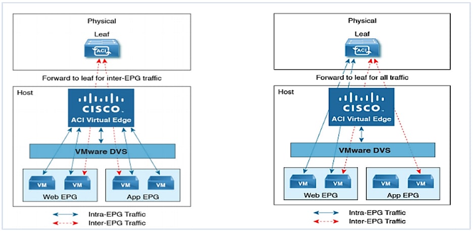
If Local switching mode is used, either a range of VLANs or a single infra-VLAN must be specified when using VLAN and VXLAN encapsulations respectively. The specified VLAN(s) have local scope as they are only significant to the layer 2 segment between Cisco AVE and ACI Leaf switch.
As stated earlier, Cisco AVE leverages the VMware vDS to operate and the VDS is configured for private VLAN (PVLAN) mode. When a Cisco AVE based VMM domain is created on Cisco APIC, they must associate the domain with a range of VLANs to be used for PVLAN pair association of port groups on the DVS. Server administrators do not need to associate PVLANs to port groups on vCenter because Cisco APIC automatically associates PVLAN pairs with the corresponding ACI EPGs.
Also, Cisco AVE can be deployed using local or remote storage – local storage is recommended. Cisco AVE virtual machine configuration can be lost if the ESXi host or Cisco AVE VM is removed or moved from vCenter.
Virtual Networking Design
This section describes the virtual networking design used in this solution.
Virtual Networking Using VMware vSphere vSwitch
The Cisco HyperFlex Installer deploys a default virtual networking on each ESXi host in the HyperFlex cluster show in - using VMware vSphere virtual switches (vSwitch). To support multiple virtual switches on a host, the Installer configures each HyperFlex host with multiple virtual NIC (vNIC) interfaces which are then used as uplinks for the different vSphere vSwitches. The vNICs are created using service profiles from Cisco UCS Manager. The VLANs for management, storage, vMotion, and application traffic are then enabled on the corresponding vNIC interfaces.
Figure 38 shows the default virtual networking deployed by the HyperFlex Installer on ESXi hosts in a cluster.
Virtual Networking Using VMware vSphere vDS
The default virtual networking deployed on Cisco HyperFlex systems can be converted to use a VMware vDS instead of the default VMware virtual switches deployed by the HyperFlex installer. Cisco ACI can manage the virtual networking using an APIC controlled VMware vSphere Distributed Switch (vDS) or Cisco ACI Virtual Edge (AVE). The VM networks in both Management and Application clusters were migrated to use an APIC controlled VMware vDS in this solution. The virtual networking deployed on ESXi hosts in the Management cluster is shown in Figure 39.

The virtual networking deployed on ESXi hosts in the Applications cluster is shown in Figure 40.
Note that the infrastructure networks remain on the default VMware vSwitch(s) in order to maximize availability and ensure access to management, storage and vMotion networks that are critical for the health of the cluster.
Validated Design – Virtual Networking on HyperFlex Nodes
The virtual networking on Cisco HyperFlex systems attached to a Cisco ACI Fabric can be converted to use either a VMware vDS or Cisco AVE instead of the default VMware virtual switches deployed by the HyperFlex installer. In this design, the virtual machines using VM networks are migrated from the VM network vSwitch to either a VMware vDS (Management cluster) or an APIC-controlled Cisco AVE switch (Application cluster). However, the default HyperFlex infrastructure networks, management, storage data and vMotion will remain on the default virtual switches created by the HyperFlex installer. The resulting ESXi networking design is therefore a combination of 3 virtual switches and a fourth virtual switch for application traffic that is migrated to either a VMware vDS or an APIC-Controlled Cisco AVE switch.
Table 2 and Table 3 lists the ESXi networking deployed by the HX Installer on the HX nodes in the Management and Application clusters respectively.
Table 2 Virtual Networking on HyperFlex Nodes in Management Cluster

Table 3 Virtual Networking on HyperFlex Nodes in Applications Cluster

Any port-groups for application virtual machines on the vswitch-hx-vm-network vSwitch and the uplinks will be migrated to Cisco AVE (Application cluster) or VMware vDS (Management cluster) using VMM integration. If Cisco AVE is used, infrastructure VLAN (v4093) is required for VxLAN tunneling. This VLAN must be added to the ACI Leaf switches and Cisco UCS Fabric Interconnects before the APIC can create the Cisco AVE switch in the vSphere environment.
HyperFlex Stretched Cluster Recommendations
For the latest HyperFlex stretched cluster recommendations, please review the following white paper: Operating Cisco HyperFlex Data Platform Stretched Clusters
vSphere High Availability Recommendations
The VMware vSphere high availability setup is critical for the operation of a HyperFlex stretched cluster. HyperFlex installation configures many VMware features that a stretched cluster requires such as vSphere high availability, DRS, virtual machine and datastore host-groups, site-affinity, and so on. In addition, customers should also enable the following vSphere high availability settings in VMware vCenter:
· vSphere Availability: vSphere high availability should be enabled but keep Proactive high availability disabled
· Failure Conditions and responses:
- Enable Host Monitoring
- For Host Failure Response, select Restart VMs
- For Response for Host Isolation, select Power off and restart VMs
- For Datastore with PDL, select Power off and restart VMs
- For Datastore with PDL, select Power off and restart VMs (conservative)
- For VM Monitoring: Customer can enable this if they prefer. It is typically disabled.
· Admission Control: select Cluster resource percentage for Define host failover capacity by
· Datastore Heartbeats: Select Use datastores only from the specified list and select HyperFlex datastores in each site
· Advanced Settings:
- select False for das.usedefaultisolationaddress
- select an IP address in Site A for das.isolationaddress0
- select an IP address in Site B for das.isolationaddress1
· For additional details, see Operating Cisco HyperFlex Data Platform Stretched Clusters white paper.
Validated Hardware and Software
Table 4 lists the hardware and software versions used during the solution validation. The versions used are in alignment with the recommended versions in the interoperability matrixes from Cisco and VMware.
Table 4 Hardware and Software Versions
Interoperability
Customers that would like to use other models of hardware or software versions in this design should verify interoperability and support using the following matrices. It is also important to review the latest release notes for the most up-to-date information on the product and software release.
· Cisco UCS and HyperFlex Hardware and Software Interoperability Tool
· Cisco ACI Recommended Release
· Cisco ACI Virtualization Compatibility Matrix
· Cisco APIC and ACI Virtual Edge Support Matrix
Solution Validation
The solution was validated in Cisco Labs to verify end-to-end functionality. The system was also validated for resiliency by failing various aspects of the system under load. Examples of the tests executed include:
· Failure and recovery of components and links within each Pod or data center site
· Failure and recovery of components and links between Pods or data center sites
· Failure events to trigger vSphere high availability between sites.
· Failure events to trigger vMotion between sites.
All tests were performed under load using load generation tools. Different IO profiles representative of customer deployments was used. VdBench with 64VMs were deployed across the 4+4 HyperFlex stretch cluster to generate load on the end-to-end solution.
The Cisco HyperFlex Stretched Cluster with Cisco ACI Multi-Pod Fabric solution for VMware vSphere deployments delivers an active-active data center architecture to protect against disasters and provide business continuity in the event of a data center-wide failure. The HyperFlex stretched cluster and the ACI Multi-Pod fabric used in the solution enables the virtual server infrastructure to be extended across different geographical sites to ensure availability to at least one data center at all times. In the event of a failure, the solution also provides quick recovery and failover with zero data-loss. The ACI Multi-Pod fabric provides the necessary Layer 2 and Layer 3 connectivity between the sites to enable the active-active data center and provide seamless connectivity for applications and services deployed in either data center. The ACI Multi-Pod fabric is centrally and uniformly managed using a single APIC cluster which greatly simplifies the administration of a multi-data center solution such as this. The APIC cluster is also distributed across both data center fabrics for higher availability. The solution was also validated in Cisco Labs to provide customers and partners with a reliable reference design to deploy their own active-active data center solutions.
Cisco HyperFlex
· Cisco HyperFlex 3.5 Stretched Cluster with Cisco ACI 4.0 Multi-Pod Fabric Design Guide: https://www.cisco.com/c/en/us/td/docs/unified_computing/ucs/UCS_CVDs/hx_35_vsi_aci_multipod_design.html
· Cisco HyperFlex 3.5 Stretched Cluster with Cisco ACI 4.0 Multi-Pod Fabric Deployment Guide: https://www.cisco.com/c/en/us/td/docs/unified_computing/ucs/UCS_CVDs/hx_35_vsi_aci_multipod.html
· Cisco HyperFlex Virtual Server Infrastructure 3.0 with Cisco ACI 3.2 and VMware vSphere 6.5: https://www.cisco.com/c/en/us/td/docs/unified_computing/ucs/UCS_CVDs/hx_30_vsi_aci_32.html
· Cisco HyperFlex 3.0 for Virtual Server Infrastructure with VMware ESXi: https://www.cisco.com/c/en/us/td/docs/unified_computing/ucs/UCS_CVDs/hyperflex_30_vsi_esxi.html
· Operating Cisco HyperFlex HX Data Platform Stretch Clusters:https://www.cisco.com/c/dam/en/us/products/collateral/hyperconverged-infrastructure/hyperflex-hx-series/operating-hyperflex.pdf
· Cisco HyperFlex Systems Stretched Cluster Guide, Release 3.5: https://www.cisco.com/c/en/us/td/docs/hyperconverged_systems/HyperFlex_HX_DataPlatformSoftware/HyperFlex_Stretched_Cluster/3_5/b_HyperFlex_Systems_Stretched_Cluster_Guide_3_5.html
· Comprehensive Documentation for Cisco HyperFlex: https://http://hyperflex.io
· Comprehensive Documentation Roadmap for Cisco HyperFlex: https://www.cisco.com/c/en/us/td/docs/hyperconverged_systems/HyperFlex_HX_DataPlatformSoftware/HX_Documentation_Roadmap/HX_Series_Doc_Roadmap.html
Cisco UCS
· Cisco Unified Computing System: http://www.cisco.com/en/US/products/ps10265/index.html
· Cisco UCS 6300 Series Fabric Interconnects: http://www.cisco.com/c/en/us/products/servers-unified-computing/ucs-6300-series-fabric-interconnects/index.html
· Cisco UCS 5100 Series Blade Server Chassis: http://www.cisco.com/en/US/products/ps10279/index.html
· Cisco UCS 2300 Series Fabric Extenders: https://www.cisco.com/c/en/us/products/collateral/servers-unified-computing/ucs-6300-series-fabric-interconnects/datasheet-c78-675243.html
· Cisco UCS 2200 Series Fabric Extenders: https://www.cisco.com/c/en/us/products/collateral/servers-unified-computing/ucs-6300-series-fabric-interconnects/data_sheet_c78-675243.html
· Cisco UCS B-Series Blade Servers: http://www.cisco.com/en/US/partner/products/ps10280/index.html
· Cisco UCS C-Series Rack Mount Servers: http://www.cisco.com/c/en/us/products/servers-unified-computing/ucs-c-series-rack-servers/index.html
· Cisco UCS VIC Adapters: http://www.cisco.com/en/US/products/ps10277/prod_module_series_home.html
· Cisco UCS Manager: http://www.cisco.com/en/US/products/ps10281/index.html
· Cisco UCS Manager Plug-in for VMware vSphere Web Client: http://www.cisco.com/c/en/us/td/docs/unified_computing/ucs/sw/vmware_tools/vCenter/vCenter_Plugin_Release_Notes/2_0/b_vCenter_RN_for_2x.html
Cisco ACI Fabric
· ACI Multi-Pod White Paper: https://www.cisco.com/c/en/us/solutions/collateral/data-center-virtualization/application-centric-infrastructure/white-paper-c11-737855.html
· Cisco ACI Multi-Pod Configuration Whitepaper: https://www.cisco.com/c/en/us/solutions/collateral/data-center-virtualization/application-centric-infrastructure/white-paper-c11-739714.html
· Verified Scalability Guide for Cisco APIC Release 4.2(4): https://www.cisco.com/c/en/us/td/docs/switches/datacenter/aci/apic/sw/4-x/verified-scalability/Cisco-ACI-Verified-Scalability-Guide-424.html
· Cisco Nexus 9000 Series Switches: http://www.cisco.com/c/en/us/products/switches/nexus-9000-series-switches/index.html
· Transceiver Compatibility Matrix for Cisco Switches: https://tmgmatrix.cisco.com/
· Cisco Application Centric Infrastructure – Data center and Virtualization: https://www.cisco.com/c/en_au/solutions/data-center-virtualization/aci.html
· Cisco Application Centric Infrastructure – Cisco Data center: https://www.cisco.com/go/aci
· Cisco ACI Fundamentals: https://www.cisco.com/c/en/us/td/docs/switches/data center/aci/apic/sw/1-x/aci-fundamentals/b_ACI-Fundamentals.html
· Cisco ACI Infrastructure Release 2.3 Design Guide: https://www.cisco.com/c/en/us/solutions/collateral/data-center-virtualization/application-centric-infrastructure/white-paper-c11-737909.pdf
· Cisco ACI Infrastructure Best Practices Guide: https://www.cisco.com/c/en/us/td/docs/switches/data center/aci/apic/sw/1-x/ACI_Best_Practices/b_ACI_Best_Practices.html
Virtualization Layer
· VMware vCenter Server: http://www.vmware.com/products/vcenter-server/overview.html
· VMware vSphere: https://www.vmware.com/products/vsphere
Security
· Integrating Cisco Umbrella to Cisco HyperFlex and Cisco UCS Solutions: https://www.cisco.com/c/dam/en/us/products/collateral/hyperconverged-infrastructure/hyperflex-hx-series/whitepaper-c11-741088.pdf
Interoperability Matrixes
· Cisco UCS and HyperFlex Hardware Compatibility Matrix: https://ucshcltool.cloudapps.cisco.com/public/
· Cisco ACI Recommended APIC and Cisco Nexus 9000 Series ACI-Mode Switches Releases: https://www.cisco.com/c/en/us/td/docs/switches/data center/aci/apic/sw/recommended-release/b_Recommended_Cisco_ACI_Releases.html
· Cisco ACI Virtualization Compatibility Matrix: https://www.cisco.com/c/dam/en/us/td/docs/Website/data center/aci/virtualization/matrix/virtmatrix.html
· Cisco APIC and ACI Virtual Edge Support Matrix: https://www.cisco.com/c/dam/en/us/td/docs/Website/data center/aveavsmatrix/index.html
· VMware Compatibility Guide: http://www.vmware.com/resources/compatibility
Archana Sharma, Technical Leader, Cisco UCS Data Center Solutions, Cisco Systems Inc.
Archana Sharma is Technical Marketing Engineer with over 20 years of experience at Cisco on a range of technologies that span Data Center, Desktop Virtualization, Collaboration, and other Layer2 and Layer3 technologies. Archana is focused on systems and solutions for Enterprise and Provider deployments, including delivery of Cisco Validated designs for over 10 years. Archana is currently working on designing and integrating Cisco UCS-based Converged Infrastructure solutions. Archana holds a CCIE (#3080) in Routing and Switching and a bachelor’s degree in Electrical Engineering from North Carolina State University.