Cisco HyperFlex 4.0 Stretched Cluster with Cisco ACI 4.2 Multi-Pod Fabric
Available Languages
Bias-Free Language
The documentation set for this product strives to use bias-free language. For the purposes of this documentation set, bias-free is defined as language that does not imply discrimination based on age, disability, gender, racial identity, ethnic identity, sexual orientation, socioeconomic status, and intersectionality. Exceptions may be present in the documentation due to language that is hardcoded in the user interfaces of the product software, language used based on RFP documentation, or language that is used by a referenced third-party product. Learn more about how Cisco is using Inclusive Language.
- US/Canada 800-553-2447
- Worldwide Support Phone Numbers
- All Tools
 Feedback
 Feedback

Cisco HyperFlex 4.0 Stretched Cluster with Cisco ACI 4.2 Multi-Pod Fabric
Deployment Guide for Cisco HyperFlex 4.0 Stretched Cluster with Cisco ACI 4.2 Multi-Pod Fabric and VMware vSphere 6.7U3
Published: July 2020
About the Cisco Validated Design Program
The Cisco Validated Design (CVD) program consists of systems and solutions designed, tested, and documented to facilitate faster, more reliable, and more predictable customer deployments. For more information, go to:
http://www.cisco.com/go/designzone.
ALL DESIGNS, SPECIFICATIONS, STATEMENTS, INFORMATION, AND RECOMMENDATIONS (COLLECTIVELY, "DESIGNS") IN THIS MANUAL ARE PRESENTED "AS IS," WITH ALL FAULTS. CISCO AND ITS SUPPLIERS DISCLAIM ALL WARRANTIES, INCLUDING, WITHOUT LIMITATION, THE WARRANTY OF MERCHANTABILITY, FITNESS FOR A PARTICULAR PURPOSE AND NONINFRINGEMENT OR ARISING FROM A COURSE OF DEALING, USAGE, OR TRADE PRACTICE. IN NO EVENT SHALL CISCO OR ITS SUPPLIERS BE LIABLE FOR ANY INDIRECT, SPECIAL, CONSEQUENTIAL, OR INCIDENTAL DAMAGES, INCLUDING, WITHOUT LIMITATION, LOST PROFITS OR LOSS OR DAMAGE TO DATA ARISING OUT OF THE USE OR INABILITY TO USE THE DESIGNS, EVEN IF CISCO OR ITS SUPPLIERS HAVE BEEN ADVISED OF THE POSSIBILITY OF SUCH DAMAGES.
THE DESIGNS ARE SUBJECT TO CHANGE WITHOUT NOTICE. USERS ARE SOLELY RESPONSIBLE FOR THEIR APPLICATION OF THE DESIGNS. THE DESIGNS DO NOT CONSTITUTE THE TECHNICAL OR OTHER PROFESSIONAL ADVICE OF CISCO, ITS SUPPLIERS OR PARTNERS. USERS SHOULD CONSULT THEIR OWN TECHNICAL ADVISORS BEFORE IMPLEMENTING THE DESIGNS. RESULTS MAY VARY DEPENDING ON FACTORS NOT TESTED BY CISCO.
CCDE, CCENT, Cisco Eos, Cisco Lumin, Cisco Nexus, Cisco StadiumVision, Cisco TelePresence, Cisco WebEx, the Cisco logo, DCE, and Welcome to the Human Network are trademarks; Changing the Way We Work, Live, Play, and Learn and Cisco Store are service marks; and Access Registrar, Aironet, AsyncOS, Bringing the Meeting To You, Catalyst, CCDA, CCDP, CCIE, CCIP, CCNA, CCNP, CCSP, CCVP, Cisco, the Cisco Certified Internetwork Expert logo, Cisco IOS, Cisco Press, Cisco Systems, Cisco Systems Capital, the Cisco Systems logo, Cisco Unified Computing System (Cisco UCS), Cisco UCS B-Series Blade Servers, Cisco UCS C-Series Rack Servers, Cisco UCS S-Series Storage Servers, Cisco UCS Manager, Cisco UCS Management Software, Cisco Unified Fabric, Cisco Application Centric Infrastructure, Cisco Nexus 9000 Series, Cisco Nexus 7000 Series. Cisco Prime Data Center Network Manager, Cisco NX-OS Software, Cisco MDS Series, Cisco Unity, Collaboration Without Limitation, EtherFast, EtherSwitch, Event Center, Fast Step, Follow Me Browsing, FormShare, GigaDrive, HomeLink, Internet Quotient, IOS, iPhone, iQuick Study, LightStream, Linksys, MediaTone, MeetingPlace, MeetingPlace Chime Sound, MGX, Networkers, Networking Academy, Network Registrar, PCNow, PIX, PowerPanels, ProConnect, ScriptShare, SenderBase, SMARTnet, Spectrum Expert, StackWise, The Fastest Way to Increase Your Internet Quotient, TransPath, WebEx, and the WebEx logo are registered trademarks of Cisco Systems, Inc. and/or its affiliates in the United States and certain other countries.
All other trademarks mentioned in this document or website are the property of their respective owners. The use of the word partner does not imply a partnership relationship between Cisco and any other company. (0809R)
© 2020 Cisco Systems, Inc. All rights reserved.
Table of Contents
Solution Deployment – ACI Fabric (Single Pod)
Initial Setup of APIC(s) in Pod-1
Deploy Spine and Leaf switches in Pod-1
Configure Pod Policies for Pod-1
Enable/Review ACI Fabric Settings
Pre-configure Access Layer Policies
Initial Setup of APIC(s) in Pod-1
Deploy Spine and Leaf Switches in Pod-1
Add Leaf Switches to the ACI Fabric
Upgrade Firmware on Leaf Switches in Pod-1 (Optional)
Add Spine Switches to the ACI Fabric
Verify Spine and Leaf Switches are Added to the ACI Fabric
Upgrade Firmware on Spine Switches in Pod-1 (Optional)
Configure Out-of-Band and In-Band Management for Switches in Pod-1
Configure Pod Policies for Pod-1
Update BGP Route Reflector Policy for Pod-1
Update Pod Profile to Apply Pod Policies
Enable/Review ACI Fabric Settings
COS Preservation (Fabric Wide Setting)
Enforce Subnet Check for Endpoint Learning (Fabric Wide Setting)
Limit IP Learning to Subnet (Bridge-domain, Optional)
IP Aging (Fabric Wide Setting)
Pre-configure Access Layer Policies
Solution Deployment – ACI Fabric (to Outside Networks from Pod-1)
Create VLAN Pool for Shared L3Out
Configure Domain Type for L3Out
Create Attachable Access Entity Profile for L3Out
Configure Tenant Networking for Shared L3Out
Configure OSPF Interface Policy for L3Out in Pod-1
Create Contracts for Shared L3Out in Pod-1
Provide Contracts for Shared L3Out in Pod-1
Configure L3Out Connectivity for Pod-1
Configure External Gateways in the Outside Network
Solution Deployment – ACI Fabric (Multi-Pod)
Deploy Inter-Pod Network (IPN)
Setup ACI Fabric for Multi-Pod
Setup Pod-2 Spine Switches, Leaf Switches, and APICs
Configure IPN Devices in Pod-1
Configure IPN Devices in Pod-2
Enable Connectivity to IPN from Pod-1
Deploy Spine and Leaf Switches in Pod-2
Update BGP Route Reflector Policy for Pod-2
Update Pod Profile to Apply Pod Policies
Enable Connectivity to IPN from Pod-2
Configure DHCP Relay on IPN Devices
Verify Pod-2 APIC is Part of the APIC Cluster
Add Pod-2 APIC as DHCP Relay Destination
Verify ACI Multi-Pod Fabric Setup
Verify OSPF Status on Spine Switches
Verify MP-BGP EVPN Status on Spine Switches
Verify COOP Status on Spine Switches
Solution Deployment – ACI Fabric (To Outside Networks from Pod-2)
Create VLAN Pool for Shared L3Out
Configure Domain Type for L3Out
Create Attachable Access Entity Profile for L3Out
Configure Tenant Networking for Shared L3Out
Configure OSPF Interface Policy for L3Out in Pod-2
Create Contracts for Shared L3Out in Pod-2
Provide Contracts for Shared L3Out in Pod-2
Configure L3Out Connectivity for Pod-2
Configure External Gateways in the Outside Network
Solution Deployment – ACI Fabric (to Cisco UCS Domains)
Deploy New Leaf Switches for Connectivity to Cisco UCS Domains
ACI Fabric Discovery of Leaf Switches
Add Nexus 9000 Series Leaf Switches to the ACI Fabric
Setup Out-of-Band and In-Band Management for New Leaf Switches
Enable Access Layer Connectivity to Cisco UCS Domains
Enable 40Gbps on Links to Cisco UCS Domain
Enable Access Layer Configuration to Cisco UCS Domain
Solution Deployment – Setup Cisco UCS Domains
Bring Up Cisco UCS Domain with Fabric Interconnects
Initial Setup of Cisco UCS Domain
Upgrade Cisco UCS Manager Software to Version 4.0(1c)
Configure Cisco UCS Call Home and Anonymous Reporting (Optional)
Configure Uplink Ports on Each FI – To Nexus Leaf Switches in ACI Fabric
Bundle Uplink Ports on each FI – To Nexus Leaf Switches in ACI Fabric
Configuration of Server Ports – To HyperFlex Servers
Auto-Discovery of Server Ports (Option 1)
Manual Configuration of Server Ports (Option 2)
Modify Chassis Discovery Policy – For Blade Servers Only (Optional)
Enable Cisco Intersight Cloud-Based Management
Solution Deployment – Foundational Infrastructure for Cisco HyperFlex
Create Foundation Tenant and VRF
Configure ACI Fabric for HyperFlex In-Band Management
Create Bridge Domain for In-Band Management
Configure Subnet Gateway for In-Band Management
Create Application Profile for In-Band Management
Create EPG for In-Band Management
Add Contract to Access Outside Networks and Services
Configure ACI Fabric for HyperFlex vMotion Traffic
Create Bridge Domain for HyperFlex vMotion Traffic
Configure Subnet Gateway for HyperFlex vMotion Traffic
Create Application Profile for HyperFlex vMotion Traffic
Create EPG for HyperFlex vMotion Traffic
Add Contract to Access Outside Networks and Services (Optional)
Solution Deployment – HyperFlex Management Cluster
Setup ACI Fabric for HyperFlex Standard Cluster
Create Static Binding for In-Band Management to HyperFlex Standard Cluster
Create Static Binding for vMotion to HyperFlex Standard Cluster
Configure ACI Fabric for Storage Data Traffic on HyperFlex Standard Cluster
Install HyperFlex Cluster (Management) using Cisco Intersight
Migrate Virtual Networking to VMware vDS on HyperFlex Management Cluster
Deploy Virtual Machines – Infrastructure Management
Configure ACI Fabric for Infrastructure Management
Deploy HX Installer Virtual Machine in the HyperFlex Management Cluster
Solution Deployment – HyperFlex Application Cluster
Setup Cisco UCS Domain for HyperFlex Stretched Cluster
Setup ACI Fabric for HyperFlex Stretched Cluster
Create Static Binding for In-Band Management to HyperFlex Stretched Cluster
Create Static Binding for vMotion to HyperFlex Stretched Cluster
Configure ACI Fabric for Storage Data Traffic on HyperFlex Stretched Cluster
Install HyperFlex Stretched Cluster (Applications) using HyperFlex Installer VM
Migrate Virtual Networking to VMware vDS on HyperFlex Application Cluster
Solution Deployment – Onboarding Multi-Tier Applications
Configure ACI constructs for Application Traffic
Create Tenant and VRF for Application
Verify Virtual Networking for the Application EPGs
Web-Tier to Shared L3Out Contract
Validated Hardware and Software
Cisco ACI Application Centric Infrastructure (ACI)
Cisco Validated Designs (CVDs) are systems and solutions that are designed, tested, and documented to facilitate and accelerate customer deployments. CVDs incorporate a wide range of technologies, products, and best-practices into a portfolio of solutions that address the business needs of our customers. CVDs based on Cisco HyperFlex deliver infrastructure and application solutions using a hyperconverged, software-defined infrastructure. For a complete portfolio of HyperFlex solutions, see: https://www.cisco.com/c/en/us/solutions/design-zone/data-center-design-guides/data-center-hyperconverged-infrastructure.html
The Virtual Server Infrastructure (VSI) solutions based on Cisco HyperFlex combine software-defined computing using Cisco UCS servers, software defined storage using Cisco HyperFlex HX Data Platform, and software-defined networking using Cisco Unified Fabric to deliver a foundational, hyperconverged infrastructure platform for Enterprise data centers. When combined with a Cisco Application Centric Infrastructure (Cisco ACI) fabric, it extends the software-defined paradigm into the data center network to deliver a comprehensive, scalable, application-centric infrastructure for Enterprise data centers.
The Cisco HyperFlex Stretched Cluster with Cisco ACI Multi-Pod Fabric solution discussed in this document, is a validated reference architecture for building an active-active data center to provide business continuity and disaster avoidance. The solution extends compute, storage, and networking across two data center locations to enable the active-active data centers. Workloads can be placed in either data center with seamless mobility between data centers. In this design, a Cisco HyperFlex stretched cluster is extended across the active-active data centers to provide the hyperconverged virtual server infrastructure in each data center. The nodes in the cluster are distributed evenly across both data centers and connect to Cisco Unified Fabric or Cisco UCS Fabric Interconnects to a Cisco ACI fabric in each location. The solution uses a Cisco ACI Multi-Pod fabric as the end-to-end data center fabric for interconnecting the data centers and to provide connectivity within each data center location. The fabric also provides Layer 2 extension and Layer 3 forwarding between data centers to enable the seamless workload mobility and connectivity between data centers. The data centers can be in geographically separate sites such as a metropolitan area or they can be in the same campus or building. The HyperFlex stretched clusters serves as an Applications cluster in this design. The solution also includes an optional HyperFlex standard cluster as a Management cluster for hosting management and other shared services directly from within the ACI fabric.
To simplify day-2 operations, the solution uses Cisco Intersight to centrally manage all virtual server infrastructure in the solution. This includes the Applications cluster, the Management cluster, and the Cisco Unified Fabrics in both locations. Cisco Intersight can also be used to manage other data center infrastructure that Enterprises have. Cisco Intersight is also used to deploy the Management cluster in the solution. Cisco Intersight is a centralized, cloud-based, software-as-a-service (SAAS) platform that simplifies operations by providing pro-active, actionable intelligence to manage and operate Enterprise data centers. Cisco Intersight provides capabilities such as Cisco Technical Assistance Center (TAC) integration for support and Cisco Hardware Compatibility List (HCL) integration for compliance that Enterprises can leverage for their Cisco HyperFlex and UCS systems in all locations. Enterprises can also quickly adopt the new features that are continuously being rolled out in Cisco Intersight. The solution also uses Cisco Network Assurance Engine (Cisco NAE), Cisco Network Insights – Advisor (Cisco NIA), and Cisco Network Insights- Resources (Cisco NIR) to further simplify operations through pro-active monitoring of the ACI Multi-Pod fabric. The three tools can comprehensively monitor the fabric, leveraging analytics and cisco expertise in the networking arena to provide assurance the network is working as intended, and to identify issues pro-actively with in-depth analysis and guidance for resolving the issues.
To ease the deployment of virtualized workloads, the solution leverages the VMM integration that ACI provides, the VMM being VMware vCenter in this case, to dynamically orchestrate and manage the virtual networking using either a VMware virtual Distributed Switch (vDS) or Cisco ACI Virtualization Edge (AVE) switch. Cisco AVE is a virtual Leaf that brings the advanced capabilities of an ACI fabric (for example, application policies, micro-segmentation, security) to the virtualization layer. In this release of the solution, VMware vDS is used in both HyperFlex standard and stretch clusters.
The Cisco HyperFlex Stretched Cluster with Cisco ACI Multi-Pod Fabric CVD consists of the following documents:
· Design Guide: Cisco HyperFlex 4.0 Stretched Cluster with Cisco ACI 4.2 Multi-Pod Fabric Design Guide
· Deployment Guide: Cisco HyperFlex 4.0 Stretched Cluster with Cisco ACI 4.2 Multi-Pod Fabric
This document is the deployment guide for the solution. The solution was built and validated using Cisco HyperFlex 4.0, Cisco Unified Computing System 4.0, Cisco ACI 4.2 Multi-Pod fabric running on Cisco Nexus family of switches and VMware vSphere 6.7U3. The design guide for the solution is available here.
Introduction
Audience
Purpose of this Document
What’s New in this Release?
· Cisco HyperFlex 4.0(2b), Cisco UCS Manager 4.0(4h), Cisco Intersight
· Cisco ACI 4.2(4i), VMware vDS 6.6.0 and VMware vSphere 6.7U3
For Cisco Intersight, since it is a SaaS platform where new features are being continuously added, a number of new capabilities and integrations have been added since the last release of this solution that customers can leverage as needed. The latest features and capabilities added to the platform are available here.
To further simplify day-2 operations through pro-active intelligence and monitoring, this release also adds the following operational tools to the solution. The Cisco Network Insights are hosted on a 3-node Cisco Application Services Engine cluster connected to the in-band management network of the ACI fabric. To support these tools, Precision Time Protocol (PTP) was also enabled in the ACI Fabric.
· Cisco Network Insights – Advisor (NIA)
· Cisco Network Insights – Resources (NIR)
· Cisco Network Assurance Engine (NAE)
Solution Summary
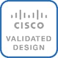
The end-to-end design for the active-active data centers in the Cisco HyperFlex Stretched Cluster with Cisco ACI Multi-Pod Fabric solution is shown in Figure 1.
As stated earlier, the active-active data centers in the solution uses a HyperFlex stretched cluster to extend the hyperconverged infrastructure across two data centers. The two data centers can be in the same site such as different buildings in a campus location or in different geographical locations. In this design, the two data centers are assumed to be in different geographical sites, separated by a distance of 75km as shown in the above figure. Cisco ACI Multi-Pod fabric provides the network fabric in each site and the connectivity between them using an Inter-Pod Network (IPN). The ACI fabric provides both layer 2 extension and layer 3 connectivity between sites that enable seamless workload placement and mobility between data centers. The fabric in each site is referred to as a Pod in the ACI Multi-Pod architecture, where each Pod is deployed as a standard Spine-Leaf architecture. The fabric is managed using a 3-node APIC cluster with two APICs in the first site and a third APIC in the second site. The physical connectivity is based on 40GbE within the Pod, and 10GbE or 40GbE to connect to IPN, outside networks and access layer devices (APICs, UCS Fabric Interconnects). A highly-resilient design is used within each Pod to ensure availability to networks and services in the event of a failure.
Each Pod also has a dedicated Layer 3 connection to outside networks to enable direct access from each data center location. As a result, a failure in the remote Pod or an IPN failure will not impact the local Pod’s reachability to/from external networks (for example, Internet or cloud) or internal networks (for example, non-ACI infrastructure or a campus network) outside the ACI fabric. The Layer 3 outside connection can be used to access services hosted outside the fabric or it can be used to host services within the ACI fabric that users outside the fabric access. In this design, all endpoints connected to the ACI fabric will share the same Layer 3 connection(s). ACI refers to this type of connection as a Shared L3Out. Shared L3Out connections are typically defined in the ACI system-defined common Tenant but it can also be in a user-defined tenant. Alternatively, a dedicated L3Out can also be defined for each tenant. In this design, two Shared L3Out connections are defined in the common Tenant - one for each Pod. The leaf switches that connect to outside networks are referred to as Border Leaf switches in the ACI architecture. A routing protocol (or static routes) is enabled on the border leaf switches and on external gateways outside the fabric to exchange routing information between ACI and outside networks. In this design, OSPF is used as the routing protocol and the border leaf switches in ACI connect to Nexus 7000 series gateways in the outside network.
The solution uses ACI multi-tenancy to provide isolate and manage the connectivity requirements. In addition to the system-defined common Tenant, the design uses the following user-defined ACI tenants to provide connectivity to HyperFlex clusters and to the workloads hosted on the clusters. Enterprises can define as many tenants as needed to meet the needs of their environment. The two user-defined tenants in this design are:
· HXV-Foundation: This tenant provides infrastructure connectivity between nodes in a HyperFlex cluster. The connectivity provided by this tenant is critical to the health and operation of the HyperFlex clusters. In this design, the infrastructure connectivity for all HyperFlex clusters in the active-active data center is enabled using this tenant.
· HXV-App-A: This tenant provides connectivity to applications, services and any other workload hosted on the HyperFlex clusters.
The solution uses two types of HyperFlex clusters – a HyperFlex standard cluster for Management (optional) and a HyperFlex stretched cluster for Applications. Both clusters connect to the ACI fabric through Cisco UCS Fabric Interconnects which in turn connects to leaf switches in the ACI fabric. Though a pair of Cisco UCS Fabric Interconnects can support several HyperFlex clusters, the HyperFlex clusters in this design connect using dedicated pairs of Fabric Interconnects and ACI leaf switches, one for each cluster. The HyperFlex stretch cluster that spans two data center locations use two pairs of Cisco UCS Fabric Interconnects and ACI leaf switches, one in each site, to connect to the ACI fabric.
For higher bandwidth and resiliency, each Fabric Interconnect pair(s) use multiple 10GbE or 40GbE links in a Port-channel (PC) configuration to connect to the upstream ACI leaf switches. In this design, the optional HyperFlex Management cluster use 10GbE links and the HyperFlex Applications cluster use 40GbE links for connecting to the ACI fabric. The downstream connectivity from Fabric Interconnects to HyperFlex nodes in the Management cluster and Applications cluster also use 10GbE and 40GbE links respectively.
ACI manages the virtual networking on both HyperFlex clusters by integrating with VMware vCenter that manages the clusters. Cisco APIC deploys a distributed virtual switch and creates port-groups as necessary to manage the virtual networking. In this release of the solution, an APIC-controlled VMware vDS is used in both the Management and Applications clusters.
The HyperFlex and Cisco UCS infrastructure in the solution are also managed from the cloud using Cisco Intersight. Cisco Intersight offers centralized management of virtualized infrastructure in any location with capabilities such as integration with Cisco TAC, proactive monitoring and analytics, integration with Cisco Hardware Compatibility List (HCL) for compliance checks, and so on.
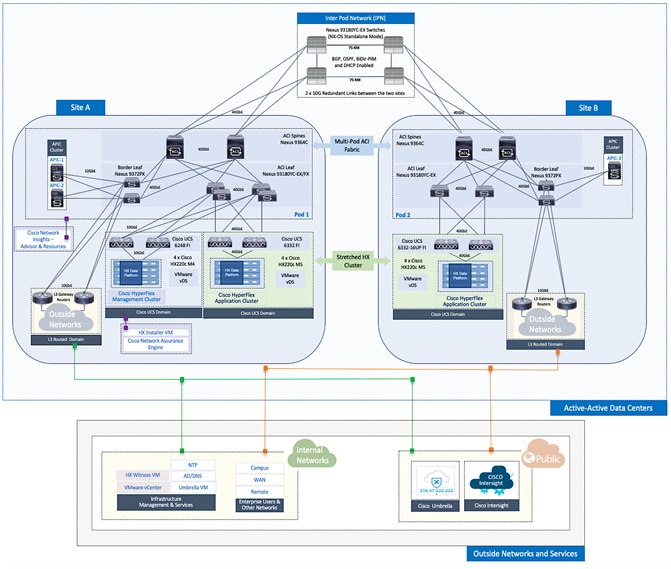
The solution was validated in Cisco Labs using the component models shown in Table 1 . Other models are supported, provided the software and hardware combinations are supported per Cisco and VMware’s hardware compatibility lists. See Solution Validation section of this document for additional details on the testing.
A high-level summary of the implementation steps for deploying the active-active data center solution is provided below. Upcoming sections will provide the detailed procedures for each implementation step.
· Deploy ACI fabric in Pod-1 where the first data center will be located. Though this is an ACI Multi-Pod fabric, the configuration at this stage is the same as that of a single-site ACI fabric.
· Enable connectivity from ACI fabric in Pod-1 to outside networks. These are networks outside the ACI fabric, either internal or external to the Enterprise. In this design, this connection provides reachability to critical functions such as VMware vCenter, HyperFlex Witness and Cisco Intersight.
· Deploy ACI Multi-Pod fabric. This involves enabling the Inter-Pod network and deploying the ACI fabric in the second data center location or Pod-2. It also includes configuration that enables Layer 2 extension and Layer 3 forwarding between Pods or data centers.
· Enable connectivity from ACI fabric in Pod-2 to outside networks. As in Pod-1, this connection provides Pod-2 with reachability to critical functions such as VMware vCenter, HyperFlex Witness and Cisco Intersight.
· Configure Foundation Tenant to enable infrastructure connectivity for Cisco HyperFlex clusters. The tenant will provide reachability between nodes in a cluster. These are networks that are required to standup the cluster such as the HyperFlex in-band management and storage-data networks. This tenant is not used for applications workloads hosted on the cluster, but it is used by management and other infrastructure VMs such as the HyperFlex Installer virtual machine used for deploying the HyperFlex stretch cluster.
· Enable access-layer connectivity from the ACI fabric in each Pod to Cisco UCS domains that connect to Cisco HyperFlex clusters. This includes connectivity to the UCS domains in Pod-1 for the optional Management cluster, and in Pod-1 and Pod-2 for the HyperFlex stretch cluster.
· Setup Cisco UCS domain for deploying Cisco HyperFlex clusters. Three UCS domains are used in this design – two for the HyperFlex stretch cluster and one for the optional Management cluster.
· Deploy and setup the HyperFlex Management Cluster (optional). This is a HyperFlex standard cluster in Pod-1 and it is deployed from the cloud using Cisco Intersight in this solution. It can also be deployed using an on-premise HyperFlex Installer VM.
· Deploy and setup the HyperFlex Applications Cluster. This is a HyperFlex stretch cluster extended across Pod-1 and Pod-2. It is deployed using the HyperFlex Installer VM hosted on the Management cluster The cluster is also enabled for Cisco Intersight management.
· On-board multi-tier applications. A separate application tenant is defined in the ACI fabric to meet the connectivity needs of the applications. Virtual networking for these workloads is automatically deployed by the APIC through integration with VMware vCenter.
![]() For this CVD, the solution setup from an earlier release of this CVD was updated to the versions and configurations needed for this release. For this reason, any initial deployment screenshots in this document are from the earlier CVD release - all other screenshots are from this release. The solution was then validated to verify the end-to-end functionality and tested for various failure scenarios to ensure the accuracy of the implementation. The deployment guide for the previously-built solution is available here.
For this CVD, the solution setup from an earlier release of this CVD was updated to the versions and configurations needed for this release. For this reason, any initial deployment screenshots in this document are from the earlier CVD release - all other screenshots are from this release. The solution was then validated to verify the end-to-end functionality and tested for various failure scenarios to ensure the accuracy of the implementation. The deployment guide for the previously-built solution is available here.
Solution Deployment – ACI Fabric (Single Pod)
This section provides detailed procedures for deploying a new Cisco ACI fabric. This fabric will serve as the first Pod or site (Pod 1 or Site A in Figure 1) in the ACI Multi-Pod fabric. The fabric will provide network connectivity for Cisco UCS domains and Cisco HyperFlex clusters that connect to it. In this solution, half the nodes in the stretched cluster and all nodes in the optional Management cluster will connect to Pod-1.
![]() The procedures in this section are the same as that for deploying a single-site ACI fabric.
The procedures in this section are the same as that for deploying a single-site ACI fabric.
Deployment Overview
A high-level overview of the steps involved in deploying a single-site ACI fabric is summarized below:
Physical Connectivity
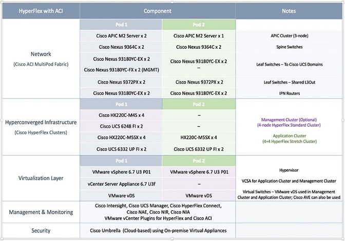
· Complete the physical cabling required to bring up an ACI fabric in Pod-1. An ACI fabric should have a minimum of two Spine switches, two Leaf switches, and a 3-node APIC cluster. In this design, a pair of spine switches and three pairs of leaf switches are deployed in Pod-1. In this section, only the leaf switches that the APICs connect to are deployed in Pod-1. The other leaf switch pairs will be deployed at a later time. Each APIC is dual-homed to a leaf switch pair to provide both switch and link-level redundancy. For APIC high-availability, a 3-node APIC cluster is used with nodes distributed across different Pods in the ACI Multi-Pod fabric. In this design, two APICs are deployed in Pod-1 and one in Pod-2. Pod-2 APIC will be deployed and added to the cluster later in the deployment – in the Deploy APIC(s) in Pod-2 section.
· Complete all out-of-band and in-band management connectivity for Pod-1. The solution uses out-of-band management to access all switches. In this CVD release, in-band management access is also added, primarily to support Cisco Network Insights tools hosted on a dedicated Cisco Application Services Engine cluster.
· Initial setup of the APICs requires access to the keyboard, video, and mouse (KVM) console through the Cisco Integrated Management Controller (CIMC) port on the APIC. Enable CIMC connectivity to APICs in Pod-1.
Initial Setup of APIC(s) in Pod-1
Complete the initial setup of the APICs in Pod-1. In Cisco ACI, all configuration is centralized and managed from the APIC - the spine and leaf switches in the fabric are not individually configured. APIC uses Link Layer Discovery Protocol (LLDP) to discover ACI capable Nexus 9000 series switches in the infrastructure (and other APICs) in the fabric. The newly discovered switches are then added, provisioned, and managed from the APIC web GUI. The initial setup establishes key parameters for the fabric such as Fabric ID, Pod ID, and address pools.
Deploy Spine and Leaf switches in Pod-1
Add spine and leaf switches in Pod-1 to the ACI fabric. APICs discover the switches in the fabric through LLDP. APICs can now add the switches to the fabric and manage them. In this step, only the APIC leaf switches are added to the fabric though the physical connectivity is in place for all
Configure Global Policies
Configure fabric-level policies such as Timezone and DNS policies.
Configure Pod Policies for Pod-1
Configure pod-level policies such as NTP, BGP Route Reflector function, Fabric Profiles and Access Policies for Pod-1.
Enable/Review ACI Fabric Settings
Review or enable settings that impact the flow of traffic between endpoints. These policies apply to all endpoints in the ACI Multi-Pod fabric.
Pre-configure Access Layer Policies
Configure common policies for access layer connection to endpoints, gateways or other devices that connect to the fabric. These policies can be re-used across all access layer connections in the ACI Multi-Pod fabric.
Physical Connectivity
Complete the physical cabling necessary to bring up an ACI Fabric in Pod-1 as shown in Figure 2. Out-of-Band (OOB) management and In-Band management connectivity for all devices and CIMC management for the APICs should also be completed – not shown in the figure.
Initial Setup of APIC(s) in Pod-1
Follow the procedures outlined in this section to do an initial setup of the APIC(s) in Pod-1.
![]() The screenshots in this section are from a previous release of this CVD. For this CVD, the previous testbed environment was upgraded and re-configured. Therefore, any screenshots showing the initial setup of the APIC cluster are based on a previous release of this CVD.
The screenshots in this section are from a previous release of this CVD. For this CVD, the previous testbed environment was upgraded and re-configured. Therefore, any screenshots showing the initial setup of the APIC cluster are based on a previous release of this CVD.
Prerequisites
KVM Console access is necessary to do an initial setup and configuration of new APIC(s). KVM access is available through CIMC and therefore access to the CIMC Management interface on each APIC is required. The following CIMC information is also needed:
· CIMC Management IP Address for the APIC(s) being setup
· CIMC log in credentials for the APIC(s) being setup
Setup Information
The parameters required for the initial setup of the APICs in Pod-1 are shown in Table 2 .
Table 2 Setup Parameters for APICs in Pod-1
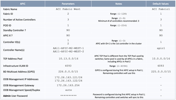
![]() TEP Address Pool specified above are specifically for the APICs and include the APICs in Pod-2. This pool is also used by the ACI fabric switches in Pod-1. The Pod-2 fabric switches use a different TEP pool though the APIC in Pod-2 will still use the above pool.
TEP Address Pool specified above are specifically for the APICs and include the APICs in Pod-2. This pool is also used by the ACI fabric switches in Pod-1. The Pod-2 fabric switches use a different TEP pool though the APIC in Pod-2 will still use the above pool.
Deployment Steps
To do an initial setup of the new APICs in Pod-1, follow these steps:
1. Use a browser to navigate to the CIMC IP address of the new APIC. Log in using admin account.
2. From the top menu, click Launch KVM. Select HTML based KVM from the drop-down list.
3. When the KVM Application launches, the initial APIC setup screen should be visible. Press any key to start the Setup Utility.
![]() If the APIC was previously configured, reset to factory defaults, and wipe it clean before proceeding.
If the APIC was previously configured, reset to factory defaults, and wipe it clean before proceeding.
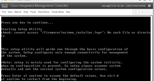
4. Use the Setup information provided above to step through the initial APIC configuration as shown below.

5. Press Enter after the last question (password for admin).
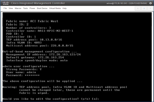
6. Review the configured information. Click y if necessary to go back and make changes, otherwise press Enter to accept the configuration.
7. Repeat steps 1-6 for the next APIC in Pod-1.
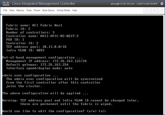
8. Review the configured information. Click y if necessary to go back and make changes, otherwise press Enter to accept the configuration.
![]() The third APIC in Pod-2 will be setup at a later time, after Inter-Pod connectivity is established between Pods.
The third APIC in Pod-2 will be setup at a later time, after Inter-Pod connectivity is established between Pods.
The APICs can now be used to configure and manage the ACI fabric by navigating to the Management IP address of any APIC in the cluster. The configuration done from one APIC will be synced to other APICs in the cluster, ensuring a consistent view of the fabric.
Deploy Spine and Leaf Switches in Pod-1
Once an APIC is up and running in Pod-1, it will discover connected spine and leaf switches in Pod-1 through LLDP. Follow the procedures outlined in this section to setup and deploy spine and leaf switches in Pod-1. The leaf switches that connect to Cisco UCS domains are added later.
![]() All screenshots in this section are from a previous release of this CVD. The previous testbed environment was upgraded and re-configured for this CVD. Therefore, any screenshots showing the initial install and setup of the fabric is from the prior CVD release.
All screenshots in this section are from a previous release of this CVD. The previous testbed environment was upgraded and re-configured for this CVD. Therefore, any screenshots showing the initial install and setup of the fabric is from the prior CVD release.
Setup Information
The setup information for deploying Spine and Leaf switches in Pod-1 are shown in the tables below.
Table 3 Setup Information - Leaf Switches
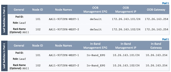
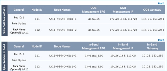
Table 4 Setup Information - Spine Switches
Add Leaf Switches to the ACI Fabric
To add the discovered Leaf and Spine switches in Pod-1 to the ACI Fabric, follow these steps:
1. Use a browser to navigate to the APIC GUI. Log in using admin account.
2. From the top menu, select Fabric > Inventory.
3. From the left navigation pane, navigate to Fabric Membership.
4. In the right navigation pane, go to the Nodes Pending Registration tab.
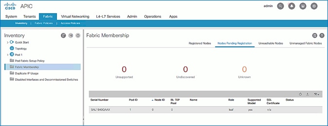
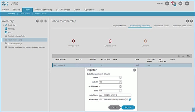
5. The newly discovered Leaf Switches will be listed with a Node ID of ‘0’. You should see at least one of the Leaf switches – the APIC is dual-homed to a pair of Leaf switches. Note that the switch’s Role is leaf.
6. Use the serial numbers to identify the new Leaf switch. Collect the setup information for this switch.
7. In the right windowpane, select the switch. Right-click and select Register.
8. In the Register pop-up window, specify the Pod ID (for example, 1), Node Id (for example, 101), Node Name for example, AA11-9372PX-WEST-1) and Rack Name (for example, AA11).
9. Click Register.
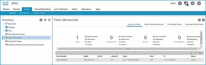
10. Switch to the Registered Nodes tab. The newly configured leaf switch should show up as Active after a few minutes.
11. In the right navigation pane, go to the Nodes Pending Registration tab.
12. Select the second (-2) Leaf switch using the serial number. Right-click and select Register.
13. In the Register pop-up window, specify the Pod ID (for example, 1), Node Id (for example, 102), Node Name for example, AA11-9372PX-WEST-2) and Rack Name (for example, AA11).
14. Click Register.
15. You should now see the Leaf switches under the Registered Nodes tab.
16. Repeat steps 1-14 to add additional leaf switch pairs to the fabric.
Upgrade Firmware on Leaf Switches in Pod-1 (Optional)
To upgrade the firmware on leaf switches in Pod-1, follow these steps:
1. Use a browser to navigate to the APIC GUI. Log in using admin account.
2. From the top menu, navigate to Admin > Firmware.
3. Select the tabs for Infrastructure > Nodes.
4. Check the Current Firmware version column for the newly deployed Leaf switches to verify they are at the desired version and that it is compatible with the APIC version running.
5. If an upgrade is not required, proceed to the next section but if an upgrade is required, use the product documentation to upgrade the switches.
Add Spine Switches to the ACI Fabric
![]() The screenshots in this section are from a previous release of the CVD available here.
The screenshots in this section are from a previous release of the CVD available here.
To add spine switches to the ACI fabric, follow these steps:
1. Use a browser to navigate to the APIC GUI. Log in using admin account.
2. From the top menu, select Fabric > Inventory.
3. From the left navigation pane, navigate to Fabric Membership.
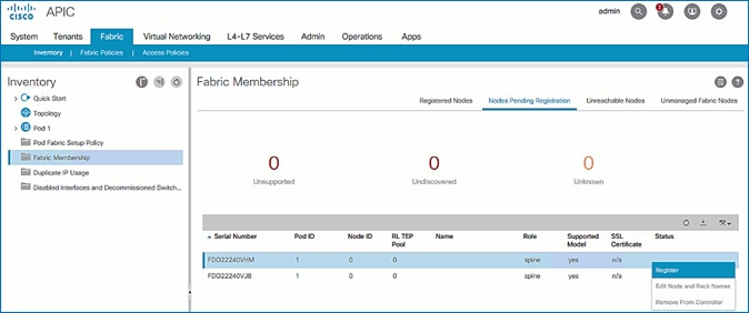
4. In the right navigation pane, go to the Nodes Pending Registration tab.
5. The newly discovered spine switches will be listed with a Node ID of ‘0’, with Role as spine.
6. Use the serial numbers to identify the spine switch pair. Collect the information for each switch.
7. Select the first (-1) spine switch using the serial number. Right-click and select Register.
8. In the Register pop-up window, specify the Pod ID (for example, 1), Node Id (for example, 111), Node Name (for example, AA11-9364C-WEST-1) and Rack Name (for example, AA11).
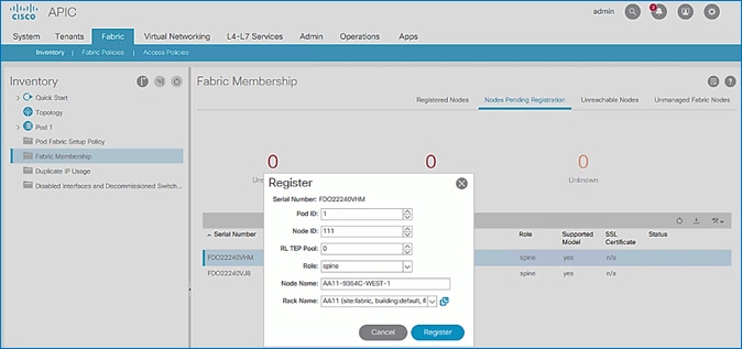
9. Click Register.
10. Select the second (-2) spine switch using the serial number. Right-click and select Register.
11. In the Register pop-up window, specify the Pod ID (for example, 1), Node Id (for example, 112), Node Name (for example, AA11-9364C-WEST-2) and Rack Name (for example, AA11).
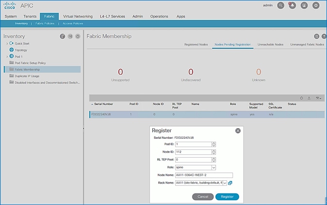
12. Click Register.
13. Repeat steps 1-12 to add additional spine switch pairs to the fabric.
Verify Spine and Leaf Switches are Added to the ACI Fabric
To verify that the spine and leaf switches have been added to the ACI fabric, follow these steps:
1. Use a browser to navigate to the APIC GUI. Log in using admin account.
2. From the top menu, select Fabric > Inventory.
3. From the left navigation pane, navigate to Fabric Membership.
4. In the right navigation pane, go to the Registered Nodes tab.
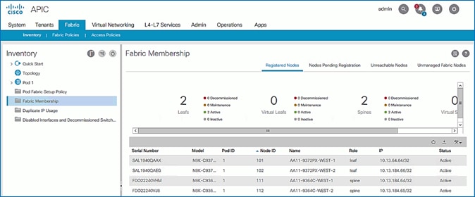
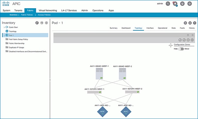
5. All Spine and Leaf switches are configured and added to the fabric. Note that the APIC has allocated IP addresses from the TEP Pool for Pod-1.
6. From the left navigation pane, select Topology to view the fabric topology after all devices have been added to the fabric.
Upgrade Firmware on Spine Switches in Pod-1 (Optional)
To upgrade the firmware on the spine switches in Pod-1, follow these steps:
1. From the top menu, navigate to Admin > Firmware.
2. Select the tabs for Infrastructure > Nodes.
3. Check the Current Firmware version column for the newly deployed Spine switches to verify they are compatible with the APIC version running.
4. If an upgrade is not required, proceed to the next section but if an upgrade is required, use the product documentation to upgrade the switches.
Configure Out-of-Band and In-Band Management for Switches in Pod-1
To configure Out-of-Band (OOB) and In-Band Management for Pod-1 Spine and Leaf switches, follow these steps using the setup information provided in Table 3 and Table 4 :
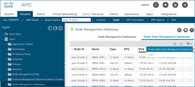
1. Use a browser to navigate to the APIC GUI. Log in using admin account.
2. From the top menu, select Tenants > mgmt.
3. From the left navigation pane, expand and select mgmt > Node Management Addresses.
4. In the right windowpane, select the tab for Static Node Management Addresses.
5. Click the arrow next to the Tools icon and select Create Static Node Management Addresses.
6. In the Create Static Node Management Addresses pop-up window, specify a Node Range (for example, 101-102), for Config: select the check-boxes for Out-of-Band Addresses and In-Band Addresses.
7. In the Out-of-Band Addresses section of the window, for the Out-of-Band Management EPG, select default from the drop-down list.
8. Specify the Out-of-Band Management IPv4 Address for the first node in the specified node range.
9. Specify the Out-of-Band Management IPv4 Gateway.
10. In the In-Band IP Addresses section of the window, for the In-Band Management EPG, select an EPG, for e.g. In-Band_EPG or select Create In-Band Management EPG from the drop-down list to create a new EPG.
11. Specify the In-Band Management IPv4 Address for the first node in the specified node range.
12. Specify the In-Band Management IPv4 Gateway.
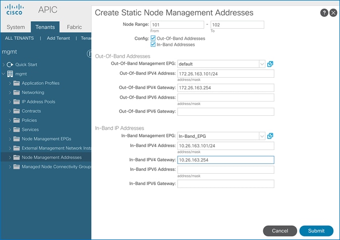
13. Click Submit to complete.
14. Click Yes in the Confirm pop-up window to assign the IP address to the range of nodes specified.
15. Repeat steps 1-14 for the remaining switches in Pod-1.
16. The switches can now be accessed directly using SSH.
![]() You can deploy contracts to limit access to the Out-of-Band Management network – see the APIC Configuration Guide for more details. Contracts were not deployed in this setup. You may also need to re-add the APIC Out-of-Band Management IP addresses under Node Management Addresses though it was configured during the initial setup of the APIC. Node IDs for APICs typically start from ‘1’.
You can deploy contracts to limit access to the Out-of-Band Management network – see the APIC Configuration Guide for more details. Contracts were not deployed in this setup. You may also need to re-add the APIC Out-of-Band Management IP addresses under Node Management Addresses though it was configured during the initial setup of the APIC. Node IDs for APICs typically start from ‘1’.
Configure Global Policies
Follow the procedures outlined in this section to configure fabric-wide policies.
Configure Time Zone Policy
To configure Time Zone for the ACI fabric, follow these steps:
1. Use a browser to navigate to APIC’s Web GUI. Log in using the admin account.
2. From the top menu, select System > System Settings.
3. In the left navigation pane, expand System Settings and select Date and Time.
4. In the right windowpane, select Policy tab. For the Time Zone, select the time zone for the deployment from the drop-down list and verify that Offset State is enabled.
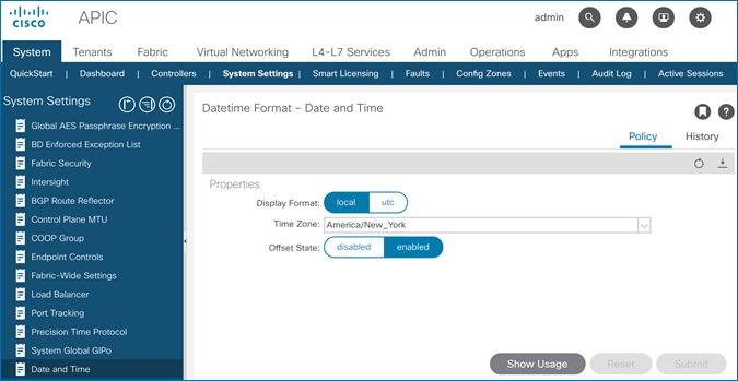
5. Click Submit.
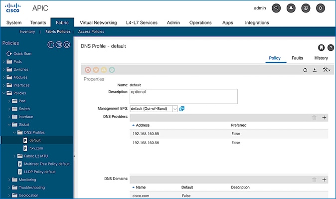
Configure DNS Policy
To configure Domain Name Server (DNS) for the ACI fabric, follow these steps:
1. Use a browser to navigate to APIC’s Web GUI. Log in using the admin account.
2. From the top menu, select Fabric > Fabric Policies.
3. In the left navigation pane, expand and select Policies > Global > DNS Profiles > default.
4. For the Management EPG, select the default (Out-of-Band) from the drop-down list if the DNS servers are reachable through the out of band management subnet.
5. Use the [+] signs to the right of DNS Providers and DNS Domains to add DNS servers and domains as needed.
Configure Pod Policies for Pod-1
To configure policies specific to a Pod in Pod-1, complete the procedures outlined in this section.
Configure NTP for Pod-1
To configure NTP for Pod-1, follow these steps using the setup information provided below:
· NTP Policy Name: Pod1-West-NTP_Policy
· NTP Server: 172.26.163.254
· Management EPG: default(Out-of-Band)
1. Use a browser to navigate to the APIC GUI. Log in using admin account.
2. From the top menu, select Fabric > Fabric Policies.
3. From the left navigation pane, navigate to Policies > Pod > Date and Time.
4. Right-click and select Create Date and Time Policy.
5. In the Create Date and Time Policy pop-up window, specify a Name for Pod-1’s NTP Policy. The Administrative State should be enabled.
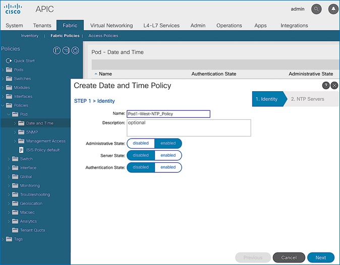
6. Click Next.
7. In Step 2 > NTP Servers, add NTP server(s) for Pod-1 using the [+] to the right of the list of servers.
8. In the Create Providers pop-up window, specify the Hostname/IP of the NTP server in the Name field. If multiple NTP Providers are being created for Pod-1, select the checkbox for Preferred when creating the preferred provider. For the Management EPG, select default (Out-of-Band) from the drop-down list.
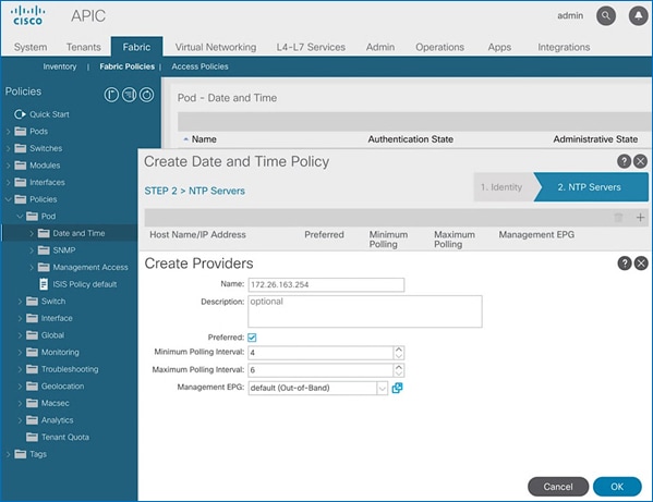
9. Click OK.
10. Click Finish.
![]() NTP policy is not in effect until it is applied using a Pod Profile in an upcoming section.
NTP policy is not in effect until it is applied using a Pod Profile in an upcoming section.
Update BGP Route Reflector Policy for Pod-1
In an ACI fabric with multiple Spine switches, a pair of spine switches are selected as BGP Route Reflectors (RR) to redistribute routes from external domains into the fabric. In a Multi-Pod ACI fabric, each Pod has a pair of RR nodes. The procedures in this section will enable RR functionality on Pod-1 spine switches.
Setup Information
· BGP Route-Reflector Policy Name: default
· Pod-1 Spine Nodes: AA11-9364C-WEST-1, AA11-9364C-WEST-2
Deployment Steps
To enable BGP Route Reflector functionality on spine switches in Pod-1, follow these steps:
1. Use a browser to navigate to the APIC GUI. Log in using admin account.
2. From the top menu, select System > System Settings.
3. From the left navigation pane, navigate to BGP Route Reflector.
4. In the right windowpane, select the Policy tab and in the Route Reflector Nodes section, click the [+] on the right to create route reflector nodes.
5. In the Create Route Reflector Node pop-up window, for the Spine Node, select the node name for the first RR spine in Pod-1.
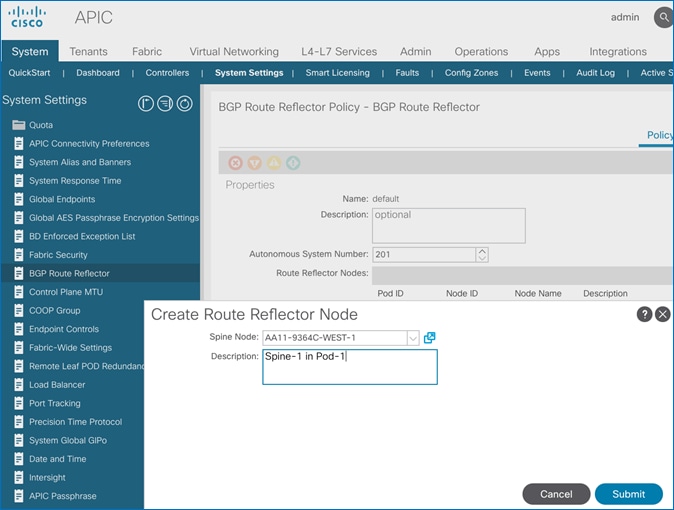
6. Click Submit.
7. Repeat steps 1-6 to add the second RR spine in Pod-1.
8. You should now see two spine switches as Route Reflectors Nodes in Pod-1.
Update Pod Profile to Apply Pod Policies
In ACI, Pod policies (for example, NTP and BGP policies) are applied through a Pod Profile. A Pod Policy Group is used to first group the policies in each Pod before they are applied using a Pod Profile. Pod-1 and Pod-2 policies are applied using the same Pod Profile. The procedures in this section will apply Pod Policies for Pod-1.
Setup Information
· Pod Policy Group Name for Pod-1: Pod1-West_PPG
· Pod Selector Name for Pod-1: Pod1-West
· Pod Profile: default
· ID for Pod-1: 1
· Pod policy names to be applied: Pod1-West-NTP_Policy, default
Deployment Steps
To apply Pod policies for Pod-1, follow these steps:
1. Use a browser to navigate to the APIC GUI. Log in using admin account.
2. From the top menu, select Fabric > Fabric Policies.
3. From the left navigation pane, navigate to Pods > Policy Groups. Right-click and select Create Pod Policy Group to create a policy group.
4. In the Create Pod Policy Group pop-up window, for Name, specify a Pod Policy Group Name. For the Date Time Policy, select the previously created NTP policy for Pod-1. Select default for the remaining policies.
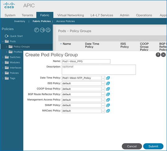
5. Click Submit.
6. From the left navigation pane, navigate to Pods > Profiles > Pod Profile default .
7. In the right windowpane, select the Policy tab and in the Pod Selectors section, click the [+] icon to add a Pod Selector.
8. In the newly created row, specify a Name. For Type, select Range. For Blocks, specify the Pod Id for Pod-1. For Policy Group, select the previously created Policy Group Name for Pod1.
9. Click Update and then Submit to apply the Pod Policies for Pod-1.
Enable/Review ACI Fabric Settings
Customers should evaluate the ACI fabric settings discussed in this section and apply it only if it is appropriate for their environment. Some settings are recommended and required, while others are recommended but optional. The procedures discussed in this section will apply the following fabric settings.
· COS Preservation (Fabric Wide)
· Enforce Subnet Check (Fabric Wide, Optional)
· Limit IP Learning to Subnet (Bridge Domain Level, Optional)
· IP Aging (Fabric Wide, Optional)
· Endpoint Learning Features
- Endpoint Dataplane Learning (Bridge Domain Level, Enabled by default)
- Layer 2 Unknown Unicast (Bridge Domain Level)
- Clear Remote MAC Entries (Bridge Domain Level, Optional)
- Unicast Routing (Bridge Domain Level)
- ARP Flooding (Bridge Domain Level)
- GARP Based Detection for EP Move Detection Mode (Bridge Domain Level)
· Jumbo Frames and MTU
Not all features will be available on first generation ACI leaf switches, but they are available on second generation switches. Models of first and second-generation leaf switches are provided below - see the Cisco Product documentation for a complete list.
· First-generation Cisco ACI leaf switches models: Nexus 9332PQ, Nexus 9372 (PX, PX-E, TX, TX-E), Nexus 9396 (PX, TX), 93120TX, 93128TX switches
· Second-generation Cisco ACI leaf switches models: Nexus 9300-EX and 9300-FX Series, Nexus 9348GC-FXP, Nexus 9336C-FX2, Nexus 93240YC-FX2 switches.
COS Preservation (Fabric Wide Setting)
Class Of Service (COS) Preservation feature in ACI preserves the COS setting in the traffic received from the endpoints. This feature should be enabled in all HyperFlex deployments to preserve the COS end-to-end across an ACI fabric, including an ACI Multi-Pod fabric. This policy has fabric-wide impact.
To enable COS Preservation, follow these steps:
1. Use a browser to navigate to APIC’s Web GUI. Log in using the admin account.
1. From the top menu, select Fabric > Access Policies.
2. In the left navigation pane, select and expand Policies > Policies > Global.
3. In the right window plane, select the QOS Class tab. For Preserve QOS, enable the checkbox for Dot1p Preserve is selected.
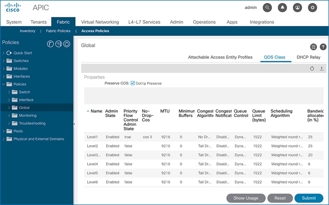
4. Click Submit and then Submit Changes in the pop-up window.
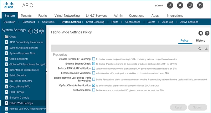
Enforce Subnet Check for Endpoint Learning (Fabric Wide Setting)
This feature limits both local and remote IP endpoint learning in a VRF to only those addresses that belong to one of the bridge domain subnets defined for that VRF. This a fabric wide policy that impacts data plane learning on all VRFs. Note that for local learning, the source IP address must also be in the same bridge domain subnet but for remote learning, the source IP just needs to match one of the bridge domain subnets for the VRF.
For subnets outside the VRF, enabling this feature will prevent all (mac, IP) address learning for local endpoints, and IP addresses for remote endpoints. This feature provides a better check than the Limit IP Learning to Subnet feature discussed in the next section, which only applies to IP addresses but not for MAC addresses. Also, it does the check only for local endpoint learning and not for remote endpoints. However the Limit IP Learning to Subnet feature is more granular in scope as it does the subnet-check on a per bridge domain basis while the Enforce Subnet Check does a check against all subnets at the VRF level and is enabled/disabled at the fabric level so it applies to all VRFs in the fabric. Limiting endpoint learning will reduce ACI fabric resource usage and therefore it is recommended but optional. This feature is disabled by default.
Some guidelines regarding this feature are provided below:
· This feature is available only on second-generation leaf switches. In a mixed environment with first and second-generation leaf switches, the first-generation switches will ignore this feature.
· Enabling this feature will enable it fabric-wide, across all VRFs though the subnet-check is for the subnets in the VRF.
· Available in APIC Releases 2.2(2q) and higher 2.2 releases and in 3.0(2h) and higher. It is not available in 2.3 or 3.0(1x) releases.
· The feature can be enabled/disabled under Fabric > Access Policies > Global Policies > Fabric Wide Setting Policy in earlier releases.
To enable the Enforce Subnet Check feature, follow these steps:
1. Use a browser to navigate to APIC’s Web GUI. Log in using the admin account.
2. From the top menu, select System > System Settings.
3. In the left navigation pane, select Fabric-Wide Settings.
4. In the right windowpane, enable check box for Enforce Subnet Check.

5. Click Submit.
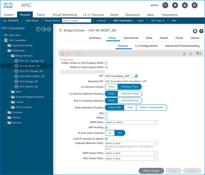
Limit IP Learning to Subnet (Bridge-domain, Optional)
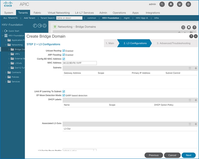
This is a bridge-domain level setting. It is superseded by the Enforced Subnet Check feature in the previous section. This feature changes the default endpoint “IP” address learning behavior of the ACI fabric. Enabling this feature will disable IP address learning on subnets that are not part of the bridge domain subnets and only learn if the source IP address belongs to one of the configured subnets for that bridge domain. A bridge domain can have multiple IP subnets and enabling this feature will limit the IP address learning to the bridge-domain subnets but will not learn addresses for subnets outside the bridge-domain. This feature will also reduce ACI fabric resource usage and therefore it is recommended but optional.
This feature is available as of APIC release 1.1(1j) and enabled by default as of APIC releases 2.3(1e) and 3.0(1k). This feature can be enabled for HyperFlex deployments as shown in the figure below.
Some guidelines regarding this feature are provided below:
· Available on first and second-generations of ACI leaf switches
· If Enforce Subnet Checking is also enabled, it supersedes this feature.
· This feature should be used when subnet-check is for a specific bridge domain (as opposed to all VRF subnets) or when you have an environment with first-generation leaf switches.
· Prior to APIC release 3.0(1k), toggling this feature with Unicast Routing enabled could result in an impact of 120s. In prior releases, ACI flushed all endpoints addresses and suspended learning on the bridge domain for 120s. The behavior in 3.0(1k) and later releases is to only flush endpoint IP addresses that are not part of the bridge domain subnets and there is no suspension of address learning.
IP Aging (Fabric Wide Setting)
IP Aging tracks and ages endpoint IP addresses that the fabric has learned, to age out stale entries. This is a fabric wide setting. This feature will also reduce ACI fabric resource usage and therefore it is recommended but optional. This feature has fabric-wide impact.
To enable IP aging, follow these steps:
1. Use a browser to navigate to APIC’s Web GUI. Log in using the admin account.
2. From the top menu, select System > System Settings.
3. In the left navigation pane, select Endpoint Controls.
4. In the right windowpane, select IP Aging tab and then Policy tab. For Administrative State, click Enabled.
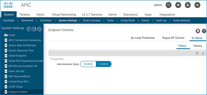
5. Click Submit.
Endpoint Learning
Endpoint learning in ACI is primarily done in hardware from data-plane traffic by examining the incoming traffic, specifically the source MAC and IP address fields in the received traffic. ACI can learn the address (MAC, IP) and location of any endpoint that sends traffic to the fabric. ACI provides several configuration settings (mostly at the bridge-domain level) that impact endpoint learning behavior.
IP vs. MAC Learning
By default, ACI learns the MAC address of all endpoints but for any “IP” learning to occur, Unicast Routing must be enabled at the bridge-domain level. Unicast Routing enables both Layer 3 forwarding and IP learning in an ACI fabric. The Endpoint Dataplane Learning feature is available at the bridge-domain level – see next section.
Silent Hosts
ACI typically learns from data-plane traffic but for silent endpoints that do not send any traffic to the fabric, ACI can also use control plane protocols such as ARP and GARP to do endpoint learning. The behaviour varies depending on whether the Bridge Domain is doing Layer 2 forwarding (Unicast Routing disabled) or Layer 3 forwarding (Unicast Routing enabled).
For bridge-domains doing Layer 2 forwarding (Unicast Routing disabled), ARP flooding can be used to learn the location of silent endpoints. ARP Flooding enables ACI to learn from the data-plane ARP traffic exchanged between the endpoints. In this scenario, the L2 Unknown Unicast option should also be set to “Flood” to prevent ACI from dropping unicast traffic destined to endpoints that it hasn’t learned of yet.
![]() APIC GUI automatically enables ARP Flooding if L2 Unknown Unicast is set to “Flood”. However, regardless of the GUI setting, APR Flooding is always enabled in hardware when Unicast Routing is disabled.
APIC GUI automatically enables ARP Flooding if L2 Unknown Unicast is set to “Flood”. However, regardless of the GUI setting, APR Flooding is always enabled in hardware when Unicast Routing is disabled.
For bridge-domains doing Layer 3 forwarding (Unicast Routing enabled), ACI can learn the location of silent or unknown hosts either by generating an ARP request or from data-plane ARP traffic. If IP subnet(s) are configured for the bridge-domain, ACI can generate an ARP request and learn the location of the unknown endpoint from its ARP response (also known as ARP gleaning). If Unicast Routing is enabled without configuring bridge-domain subnets (not recommended), ACI cannot initiate ARP requests. However, ACI can still learn their location from the data-plane ARP traffic. Though ARP Flooding is not necessary in first scenario, it should be enabled so that if the endpoint moves, ACI can learn the new location quickly rather than waiting for ACI to age out the entry for the endpoint. ACI can also detect endpoint moves using GARP by enabling the GARP-based endpoint move detection feature.
![]() ARP Flooding must be enabled for GARP-based endpoint move detection feature.
ARP Flooding must be enabled for GARP-based endpoint move detection feature.
Local vs. Remote Endpoints
Endpoint learning in ACI also depends on whether the endpoints are local or remote endpoints. For a given leaf switch, local endpoints are local to that leaf switch while remote endpoints connect to other leaf switches. Local and remote endpoints are also learned from data-plane traffic. However, unlike local endpoints, ACI typically learns either the MAC or IP address of remote endpoints but not both. The local endpoints information is sent to the Spine switches that maintain the endpoint database, but remote endpoints are maintained on the leaf switches. Remote entries are also aged out sooner than local endpoints by default.
As stated earlier, ACI provides several options that impact endpoint learning. These settings are covered in more detail in the upcoming sections.
IP Dataplane Learning
IP Dataplane Learning is bridge-domain level setting that enables/disables “IP” learning in the data-plane. This feature was referred to as Endpoint Dataplane Learning in earlier releases. The feature is available as of APIC release 2.0(1m) and it is enabled by default as shown in the figure below:
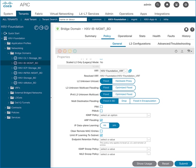
L2 Unknown Unicast
L2 Unknown Unicast is a bridge-domain level setting that specifies how unknown Layer 2 unicast frames should be forwarded within the fabric. This field can be set to “Flood” or “Hardware Proxy” (default) mode. In “Flood mode”, the unknown Layer 2 unicast frames are flooded across all ports in the bridge-domain using the bridge-domain specific multicast tree. In “Hardware Proxy” mode, the unknown unicast frames are sent to the spine switch to do a lookup in the endpoint mapping database. However, if the spine has not learned the address of that endpoint, the unicast traffic will be dropped by the fabric. For this reason, if a Layer 2 bridge-domain has silent endpoints, the L2 Unknown Unicast field should always be set to “Flood”.
The default setting for L2 Unknown Unicast is “Hardware-Proxy” but in this design, this field is set to “Flood” for deployments that may have silent hosts. This feature can be enabled as shown in the figure below:
This feature requires ARP Flooding to be enabled on the bridge-domain. Customers may also want to enable the Clear Remote MAC Entries setting. See upcoming sections for additional information on these two settings.
Clear Remote MAC Entries
This is a bridge-domain level setting that clears the remote Layer 2 MAC addresses on other switches when the corresponding MAC addresses (learnt on a vPC) are deleted from a local switch. The entries are cleared on all remote switches if it is deleted on a local switch. The setting is visible in the GUI when L2 Unknown Unicast is set to “Flood”. This feature is optional but recommended for deployments that may have silent hosts.
Unicast Routing
Unicast Routing setting on the bridge-domain enables both Layer 3 forwarding and “IP” learning in an ACI fabric. The IP endpoint learning is primarily done from the data plane traffic but ACI can also initiate ARP requests to do endpoint learning in the control plane. ACI can originate ARP requests for unknown endpoints if both Unicast Routing and bridge-domain subnet is configured. However, ACI cannot generate ARP requests if a subnet is not configured for the bridge-domain, but it can still learn their location from the data-plane ARP traffic if ARP Flooding is enabled. In this design, Unicast Routing is enabled on HyperFlex bridge-domains except for the storage-data bridge-domain.
ARP Flooding
ARP Flooding is used for both Layer 2 (Unicast Routing disabled) and Layer 3 bridge-domains (Unicast Routing enabled). By default, ACI fabric will treat ARP requests as unicast packets if Unicast Routing is enabled and forward them using the target IP address in the ARP packets. It will not flood the ARP traffic to all the leaf nodes in the bridge domain. However, the ARP Flooding setting provides the ability to change this default behavior and flood the ARP traffic fabric-wide to all the leaf nodes in a given bridge domain. See Endpoint Learning section above for other scenarios that require ARP Flooding. This feature can be enabled as shown in the figure below.
ARP Flooding is also required in environments that use Gratuitous ARP (GARP) to indicate an endpoint move. If an endpoint move occurs on the same EPG interface, GARP feature must be enabled in ACI to detect the endpoint move – see GARP based Detection section for more details. This feature is disabled by default but it is enabled in this design for deployments that may have silent hosts or require GARP.
GARP-based Detection
Gratuitous ARP (GARP) based detection setting enables ACI to detect an endpoint IP move from one MAC address to another when the new MAC is on the same EPG interface as the old MAC. ACI can detect all other endpoint IP address moves such as moves between ports, switches, EPGs or bridge-domains but not when it occurs on the same EPG interface. With this feature, ACI can use GARP to learn of an endpoint IP move on the same EPG interface. This is a bridge-domain level setting that can be enabled as shown in the figure below.
Note that ARP Flooding must be enabled to use this feature. GARP-based detection setting will not be visible on the GUI until ARP Flooding is enabled on the bridge domain.
Jumbo Frames and MTU
Traditional switching fabrics typically us a 1500B MTU and must be configured to support Jumbo frames. However, the ACI fabric, by default uses an MTU of 9150B on core facing ports of leaf and spine switches and 9000B on access ports of leaf switches. Therefore, no configuration is necessary to support Jumbo frames on an ACI fabric.
Pre-configure Access Layer Policies
Fabric Access Policies are policies that are applied to access layer connections, typically on leaf switches. The access layer connections can be to a physical domain or a virtual domain managed by a Virtual Machine Manager (VMM). The physical domains in this design include vPC connections to Cisco UCS/HyperFlex domain and Layer 3 connections to external networks. Cisco recommends configuring all policies explicitly even when the policies match the defaults to avoid issues in the future as defaults can change in newer releases. Policies can be re-used across the fabric to configure any number of access layer. The procedures in this section will pre-configure policies that will be used in later stages of the deployment.
Setup Information
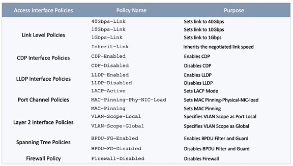
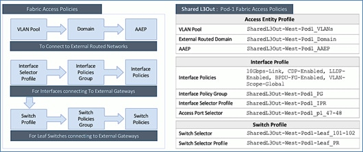
The pre-configured policies used in this design are summarized in Table 5 .
Table 5 Fabric Access Policies
Deployment Steps
To configure all policies from the following location in the GUI, follow these steps:
1. Use a browser to navigate to the APIC GUI. Log in using the admin account.
2. From the top navigation menu, select Fabric > Access Policies.
3. From the left navigation pane, select and expand Policies > Policies > Interface.
4. Create all the policies in Table 5 by following the steps in the next sections.
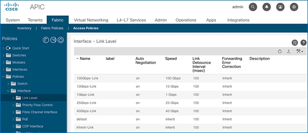
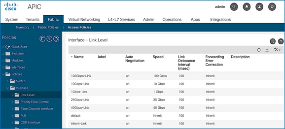
Create Link Level Policies
To create the link level policies to specify link speeds of 1/10/40-Gbps and other link policies, follow these steps:
1. From the left navigation pane, select Link Level. Right-click and select Create Link Level Policy.
2. In the Create Link Level Policy pop-up window, specify the policy Name. For the Speed, select 1Gbps from the drop-down list.
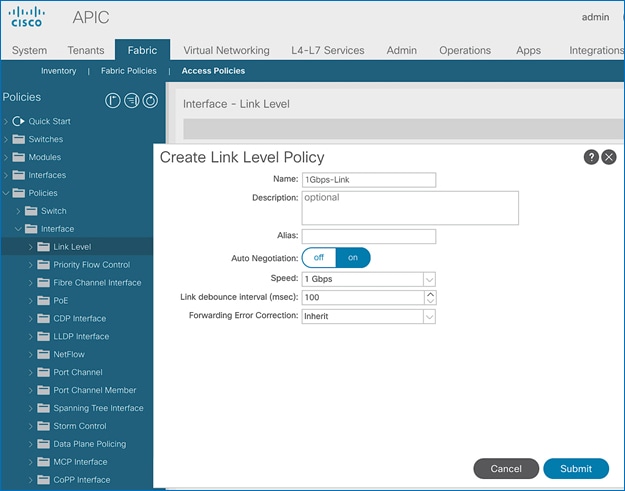
3. Click Submit to complete creating the policy.
4. Repeat steps 1-3 to create a link policies for 10Gbps, 40Gbps and for any other speeds as needed. Also create an inherit link policy as shown below.
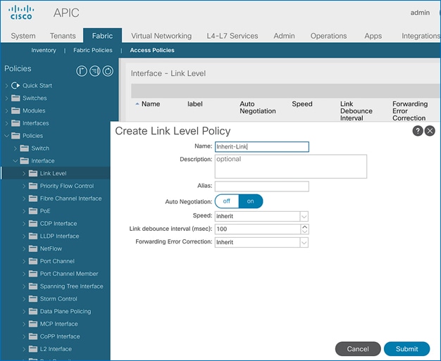
5. Click Submit to complete. You should now have the following Link policies in place:
Create CDP Interface Policies
To create CDP interface policies, follow these steps:
1. From the left navigation pane, select CDP Interface. Right-click and select Create CDP Interface Policy.
2. In the Create CDP Interface Policy pop-up window, specify the policy Name. For Admin State, click Enabled.
3. Click Submit to complete creating the policy.
4. Repeat steps 1-3 to create a policy to disable CDP. The Admin State for this policy should be Disabled.
Create LLDP Interface Policies
To create LLDP interface policies, follow these steps:
1. From the left navigation pane, select LLDP Interface. Right-click and select Create LLDP Interface Policy.
2. In the pop-up window, specify a Name. For Receive and Transmit State, click Enabled.
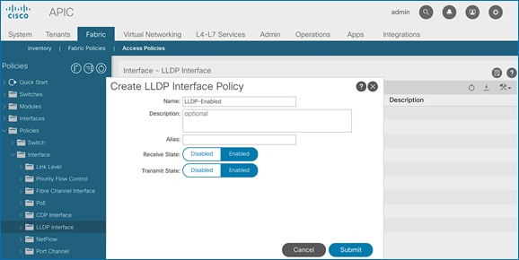
3. Click Submit to complete creating the policy.
4. Repeat steps 1-3 to create a policy to disable LLDP. The Receive and Transmit states for this policy should be Disabled.
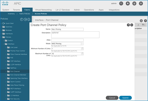
Create Port Channel Policies
To create port channel policies, follow these steps:
1. From the left navigation pane, select Port Channel. Right-click and select Create Port Channel Policy.
2. In the Create Port Channel Policy pop-up window, specify a Name for the policy. For the Mode, select LACP-Active from the drop-down list. Leave everything else as-is.
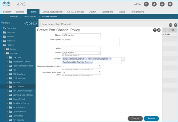
3. Click Submit to complete creating the policy.
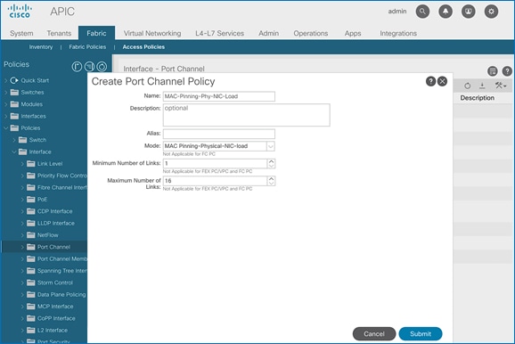
4. Repeat steps 1-3 to create a port-channel policy for mac-pinning as shown below.
5. Click Submit to complete creating the policy.
6. Repeat steps 1-3 to create a policy for mac-pinning based on physical NIC load as shown below.
Create L2 Interface (VLAN Scope) Policies
To create L2 interface policies, follow these steps:
1. From the left navigation pane, select L2 Interface. Right-click and select Create L2 Interface Policy.
2. In the Create L2 Interface Policy pop-up window, specify a name for the policy. For VLAN Scope, select Port Local scope.
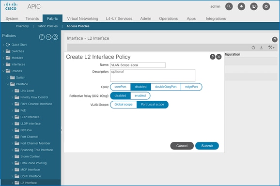
3. Click Submit to complete creating the policy.
4. Repeat steps 1-3 to create a L2 Interface policy for VLAN scope global. The VLAN Scope for this policy should be Global scope.
Create Spanning Tree Interface Policies
To create spanning tree interface policies, follow these steps:
1. From the left navigation pane, select Spanning Tree Interface. Right-click and select Create Spanning Tree Interface Policy.
2. In the Create Spanning Tree Interface Policy pop-up window, specify a policy Name. For Interface Controls, select the checkbox for BPDU Filter enabled and BPDU Guard enabled.
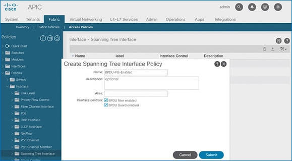
3. Click Submit to complete creating the policy.
4. Repeat steps 1-3 to create a policy to disable BPDU Filter and Guard. The Interface Controls for this policy should leave both BPDU filter enabled and BPDU Guard enabled unchecked.
Create Firewall Policy
To create a firewall policy, follow these steps:
1. From the left navigation pane, select Firewall. Right-click and select Create Firewall Policy.
2. In the Create Firewall Policy pop-up window, specify a policy name. For Mode, select Disabled.
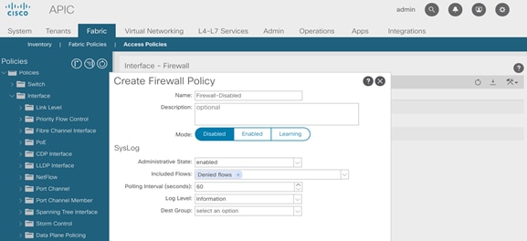
3. Click Submit to complete creating the policy.
The procedures outlined in this section will deploy a shared Layer 3 outside (Shared L3Out) connection in Pod-1 for reachability to networks outside the ACI fabric.
Deployment Overview
In this design, the Shared L3Out connection is established in the system-defined common Tenant so that it can be used by all tenants in the ACI fabric. Tenants must not use overlapping addresses when connecting to the outside networks using a shared L3Out connection. The connectivity is between border leaf switches in Pod-1 and pair of Nexus 7000 switches in the same location. The Nexus 7000 routers serve as external gateways to networks outside the fabric. OSPF is utilized as the routing protocol to exchange routes between the two networks. Some additional details of this connectivity are provided below:
· A pair of Nexus 7000 routers are connected to a pair of border leaf switches using four 10GbE interfaces – for a total of 4 links. The border leaf switches were deployed earlier. Each link is a separate routed link.
· VLANs are used for connectivity across the 4 links – for a total of 4 VLANs. VLANs are configured on separate sub-interfaces.
· A dedicated VRF common-SharedL3Out_VRF is configured in Tenant common for this connectivity.
· Fabric Access Policies are configured on the ACI border leaf switches to connect to the external routed domain or Layer 3 Outside (L3Out) domain (via Nexus 7000s) using VLAN pool (vlans: 311-314).
· The shared Layer 3 Out created in common Tenant “provides” an external connectivity contract that can be “consumed” by any tenant.
· The Nexus 7000s are configured to originate and send a default route to the Nexus 9000 leaf switches using OSPF.
· ACI leaf switches in Pod-1 advertise tenant subnets to Nexus 7000 switches in Pod-1.
· Host Routing - In ACI 4.0 release and later, an ACI fabric can also advertise host routes if it is enabled at the bridge-domain level. In this design, host routing is critical for advertising reachability to HyperFlex stretched cluster endpoints from outside the fabric since the nodes are located in different sites but in the same IP subnet. In this design, host-routing enables VMware vCenter and HyperFlex Witness in a third location (outside the ACI fabric) to reach the HyperFlex stretch cluster nodes are in the same subnet but in different subnets. This feature is critical to the operation of the HyperFlex stretch cluster in this design.
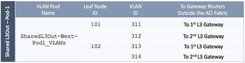
Create VLAN Pool for Shared L3Out
In this section, a VLAN pool is created to enable connectivity to networks outside the ACI fabric. The VLANs in the pool are for the individual routed links that connect the ACI border leaf switches to the gateway routers outside the fabric in Pod-1.
Setup Information
Table 6 VLAN Pool for Shared L3Out in Pod-1
Deployment Steps
To configure a VLAN pool to connect to external gateways in Pod-1, follow these steps:
1. Use a browser to navigate to the APIC GUI. Log in using the admin account.
2. From the top navigation menu, select Fabric > Access Policies.
3. From the left navigation pane, expand and select Pools > VLAN.
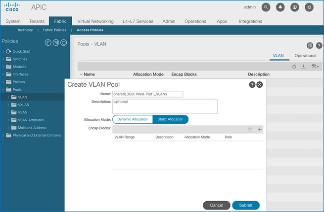
4. Right-click and select Create VLAN Pool.
5. In the Create VLAN Pool pop-up window, specify a Name and for Allocation Mode, select Static Allocation. For Encap Blocks, click on the [+] icon on the right to add VLANs to the VLAN Pool.
6. In the Create Ranges pop-up window, configure the VLANs for the border leaf switches that connect to external gateways outside the ACI fabric. Leave the remaining parameters as is.
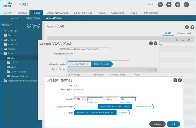
7. Click OK. Use the same VLAN ranges on the external gateway routers that connect to the ACI Fabric.
8. Click Submit to complete.
Configure Domain Type for L3Out
Follow the procedures outlined in this section to configure a domain type for the L3Out in Pod-1.
Setup Information
Table 7 Domain Type for Shared L3Out in Pod-1
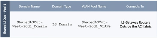
Deployment Steps
To specify the domain type for the L3Out in Pod-1, follow these steps:
1. Use a browser to navigate to the APIC GUI. Log in using the admin account.
2. From the top navigation menu, select Fabric > Access Policies.
3. From the left navigation pane, expand and select Physical and External Domains > L3 Domains.
4. Right-click on L3 Domains and select Create L3 Domain.
5. In the Create L3 Domain pop-up window, specify a Name. For the VLAN Pool, select the previously created VLAN pool from the drop-down list.
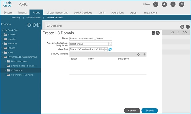
6. Click Submit to complete.
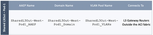
Create Attachable Access Entity Profile for L3Out
To configure an Attachable Access Entity Profile (AAEP) for the L3Out in Pod-1, follow the procedures outlined in this section.
Setup Information
Table 8 AAEP for Shared L3Out in Pod-1
Deployment Steps
To create an AAEP for the L3Out in Pod-1, follow these steps:
1. Use a browser to navigate to the APIC GUI. Log in using the admin account.
2. From the top navigation menu, select Fabric > Access Policies.
3. From the left navigation pane, expand and select Policies > Global > Attachable Access Entity Profiles.
4. Right-click and select Create Attachable Access Entity Profile.
5. In the Create Attachable Access Entity Profile pop-up window, specify a Name. Under Domains, click on the [+] icon on the right-side of the window and select the previously created domain for the Domain Profile.
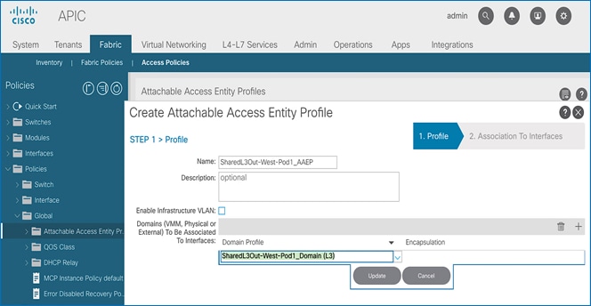
6. Click Update. You should now see the selected domain and the associated VLAN Pool.
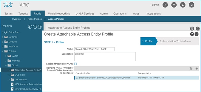
7. Click Next. This profile is not associated with interfaces at this time.
8. Click Finish to complete.
Configure Interfaces to L3Out
Follow the procedures outlined in this section to configure interfaces to the external routed domain in Pod-1.
Setup Information
Border leaf switches (Node ID: 101,102) in Pod-1 connect to external gateways using 10Gbps links, on ports 1/47 and 1/48. The access layer setup information for this connection is provided below.
Create Interface Policy Group for L3Out Interfaces
To create an interface policy group for the L3Out in Pod-1, follow these steps:
1. Use a browser to navigate to the APIC GUI. Log in using the admin account.
2. From the top navigation menu, select Fabric > Access Policies.
3. From the left navigation pane, expand and select Interfaces > Leaf Interfaces > Policy Groups > Leaf Access Port. Right-click and select Create Leaf Access Port Policy Group.
4. In the Create Leaf Access Port Policy Group pop-up window, specify a Name and select the applicable interface policies from the drop-down list for each field.
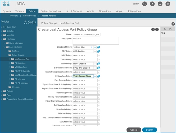
5. For the Attached Entity Profile, select the previously created AAEP to external routed domain.
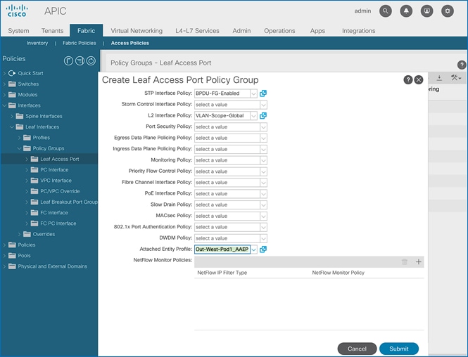
6. Click Submit to complete.
Create Interface Profile for L3Out Interfaces
To create an interface profile for the L3Out in Pod-1, follow these steps:
1. Use a browser to navigate to the APIC GUI. Log in using the admin account.
2. From the top navigation menu, select Fabric > Access Policies.
3. From the left navigation menu, expand and select Interfaces > Leaf Interfaces > Profiles. Right-click and select Create Leaf Interface Profile.
4. In the Create Leaf Interface Profile pop-up window, specify a Name. For Interface Selectors, click on the [+] icon to select access ports to apply interface policies to. In this case, the interfaces are access ports that connect Border leaf switches to gateways outside ACI.
5. In the Create Access Port Selector pop-up window, specify a selector Name. For the Interface IDs, specify the access ports connecting to the two external gateways. For the Interface Policy Group, select the previously created Policy Group from the drop-down list.
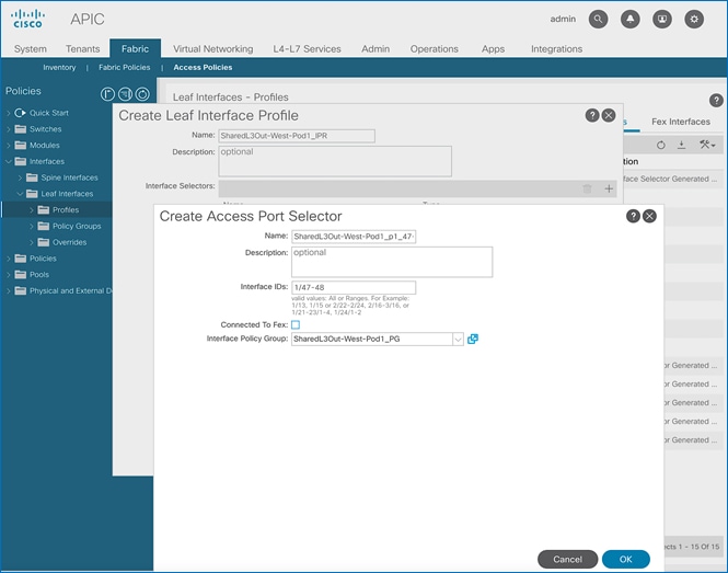
6. Click OK to close the Create Access Port Selector pop-up window.
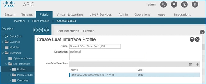
7. Click Submit to complete.
Create Leaf Switch Profile for L3Out
To create a leaf switch profile for the L3Out in Pod-1, follow these steps:
1. Use a browser to navigate to the APIC GUI. Log in using the admin account.
2. From the top navigation menu, select Fabric > Access Policies.
3. From the left navigation menu, expand and select Switches > Leaf Switches > Profiles.
4. Right-click and select Create Leaf Profile.
5. In the Create Leaf Profile pop-up window, specify a profile Name. For Leaf Selectors, click the [+] to select the Leaf switches to apply the policies to. In this case, the Leaf switches are the border leaf switches that connect to the gateways outside ACI.
6. Under Leaf Selectors, specify a Name. For the Interface IDs, specify the access ports connecting to the two external gateways. For Blocks, select the Node IDs of the border leaf switches from the drop-down list.
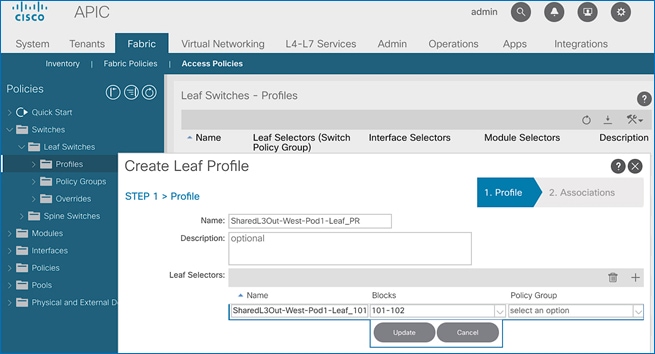
7. Click Update.
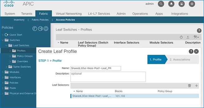
8. Click Next.
9. In the Associations window, select the previously created Interface Selector Profiles from the list.
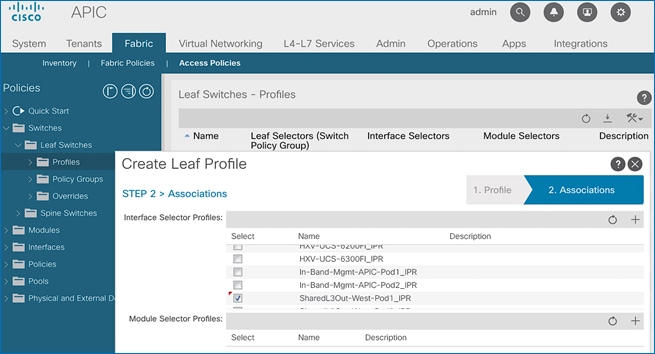
10. Click Finish to complete.
Configure Tenant Networking for Shared L3Out
The procedures in this section will configure the tenant networking to connect to networks outside the ACI fabric.
Setup Information

Deployment Steps
To configure tenant networking for the L3Out in Pod-1, follow these steps:
1. Use a browser to navigate to the APIC GUI. Log in using the admin account.
2. From the top navigation menu, select Tenants > common.
3. From the left navigation pane, select and expand Tenant common > Networking > VRFs.
4. Right-click and select Create VRF.
5. In the Create VRF pop-up window, STEP 1 > VRF, specify a Name (for example, common-SharedL3Out_VRF). Disable the check-box for Create a Bridge Domain.
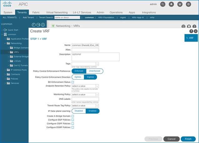
6. Click Finish to complete.
Configure OSPF Interface Policy for L3Out in Pod-1
The procedures in this section will configure OSPF interface policy for L3Out connectivity for Pod-1.
Setup Information
Table 9 OSPF Interface Policy for L3Out – Pod-1
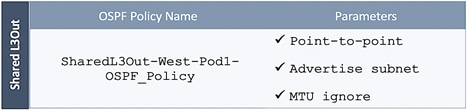
Deployment Steps
To configure OSPF interface policy for L3Out in Pod-1, follow these steps:
1. Use a browser to navigate to the APIC GUI. Log in using the admin account.
2. From the top navigation menu, select Tenants > common.
3. In the left navigation pane, select and expand common > Policies > Protocol > OSPF > OSPF Interface. Right-click and select Create OSPF Interface Policy.
4. In the Create OSPF Interface Policy pop-up window, specify a Name. For Network Type, select Point-to-Point. For Interface Controls, select the checkboxes for Advertise subnet and MTU ignore.
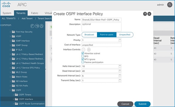
5. Click Submit.
Create Contracts for Shared L3Out in Pod-1
The procedures in this section will create contracts that provide access to external or outside networks.
Setup Information
Table 10 Shared L3Out Contract
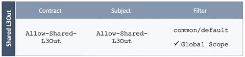
Deployment Steps
To create contracts for L3Out in Tenant common, follow these steps:
1. Use a browser to navigate to the APIC GUI. Log in using the admin account.
2. From the top navigation menu, select Tenants > common.
3. In the left navigation pane, select and expand Tenant common > Contracts.
4. Right-click Contracts and select Create Contract.
5. In the Create Contract pop-up window, specify a Name. For Scope, select Global from the drop-down list to enable the contract to be consumed by all tenants.
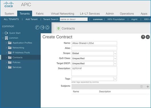
6. For Subjects, click [+] on the right side to add a contract subject.
7. In the Create Contract Subject pop-up window, specify a Name.
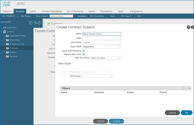
8. For Filters, click [+] on the right side to add a filter.
9. Under Filters, for Name, select default (common) from the drop-down list to use the default filter.

10. Click Update.
11. Click OK to complete creating the contract subject.
12. Click Submit to complete creating the contract.
Provide Contracts for Shared L3Out in Pod-1
The procedures in this section will provide the contract to access external or outside networks from Pod-1.
Setup Information
· L3Out in Pod-1: SharedL3Out-West-Pod1_RO
· External EPG in Pod-1: Default-Route
· Contract Name: Allow-Shared-L3Out (in common Tenant )
Deployment Steps
To provide contracts for external routed networks from Pod-1, follow these steps:
1. Use a browser to navigate to the APIC GUI. Log in using the admin account.
2. From the top navigation menu, select Tenants > common.
3. In the left navigation pane, select and expand common > Networking > L3Outs.
4. Select and expand the recently created L3Out for Pod-1.
5. Select and expand External EPGs.
6. Select the recently created L3Out EPG for Pod-1.
7. In the right windowpane, select the tab for Policy and then Contracts.
8. In the Provided Contracts tab, click on the [+] icon on the right to add a Provided Contract.
9. For Name, select the previously created contract from the drop-down list.
10. Click Update.
11. Other Tenants can now ‘consume’ this contract to route traffic outside the ACI fabric. This deployment uses a default filter to allow all traffic.
![]() Customers can modify this contract as needed to meet the needs of their environment.
Customers can modify this contract as needed to meet the needs of their environment.
Configure L3Out Connectivity for Pod-1
The procedures in this section will configure L3Out connectivity for Pod-1.
Setup Information
Table 11 L3Out Connectivity– Pod-1
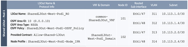
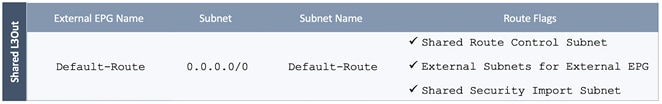
Deployment Steps
To configure L3Out connectivity to outside networks in Pod-1, follow these steps:
1. Use a browser to navigate to the APIC GUI. Log in using the admin account.
2. From the top navigation menu, select Tenants > common.
3. In the left navigation pane, select and expand common > Networking > L3Outs. Right-click and select Create L3Out.
4. In the Create L3Out pop-up window, specify a Name. Select the check box for OSPF. Specify the OSPF Area ID (should match the external gateway configuration). For VRF, select the previously created VRF from the drop-down list. For L3 Domain, select the previously created domain for Pod-1 from the drop-down list.
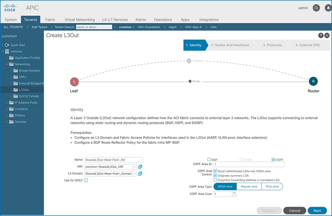
5. Click Next.
6. In the Nodes and Interfaces window, uncheck the box for Use Defaults and specify a Node Profile Name(optional). For the Interface Types, select Routed Sub. Under Nodes, for the Node ID, select the first border gateway node from the drop-down list. Then configure the interfaces on this border gateway that connects to the external gateways using the setup information provided earlier. Click on the [+] icon to right of the first interface to add the second interface.
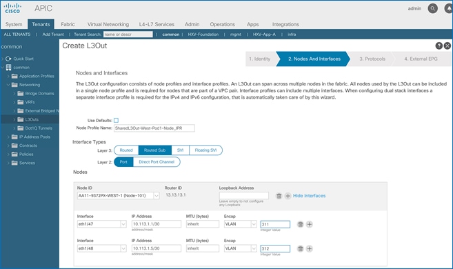
7. Click on the [+] icon to right of the first node to add the second node and click on the [+] icon to right of the first interface to add the second interface on this node.
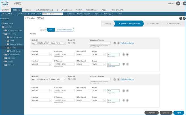
8. Click Next.
9. In the Protocols window, select the previously created OSPF interface policy from the drop-down list.
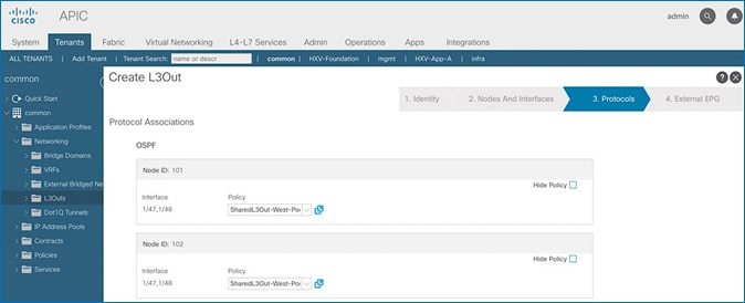
10. Click Next.
11. In the External EPG window, specify a Name (for example, Default-Route). For the Provided Contract, select the previously created contract from the drop-down list. Disable the check-box for Default EPG for all external networks.
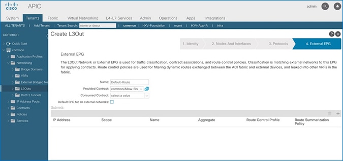
12. In the Subnets section of the window, click on the [+] icon on the right side of the window to add an external network.
13. In the Create Subnet pop-up window, for the IP Address, enter a route (for example, 0.0.0.0/0). Specify a Name (for example, Default-Route). Select the checkboxes for Shared Route Control Subnet, External Subnets for External EPG, and Shared Security Import Subnet.
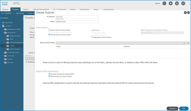
14. Click OK to complete creating the subnet.
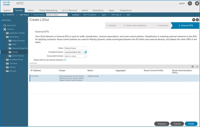
15. Click Finish to complete the L3Out connectivity in Pod-1.
Configure External Gateways in the Outside Network
This section provides a sample configuration from the external Layer 3 Gateways routers that connect to Pod-1. The gateways are in the external network and peer using OSPF to two ACI border leaf switches in Pod-1. Nexus 7000 routers are used as External gateway routers in this design, but other Cisco models can also be used.
![]() The gateway configuration provided in this section is not the complete configuration – only the relevant portions are included below.
The gateway configuration provided in this section is not the complete configuration – only the relevant portions are included below.
Enable Protocols
The protocols used between the ACI border leaf switches and external gateways have to be explicitly enabled on Nexus platforms used as external gateways in this design. The configuration to enable these protocols are provided below.
Table 12 Protocols Enabled
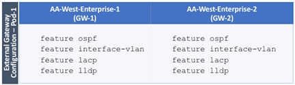
Configure OSPF
OSPF is used between the external gateways and ACI border leaf switches to exchange routing between the two domains. The global configuration for OSPF is provided below. Loopback is used as the router IDs for OSPF. Note that interfaces between ACI border leaf switches will be in OSPF Area 10.
Table 13 Routing Protocol Configuration on External Gateways
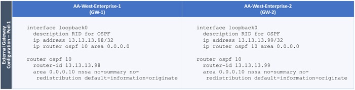
Configure Interfaces
The interface level configuration for connectivity between external gateways and ACI border leaf switches in Pod-1 is provided below. Note that interfaces to ACI are in OSPF Area 10 while the loopbacks and port-channels between the gateways are in OSPF Area 0.
Table 14 Interface Configuration – To ACI Border Leaf Switches
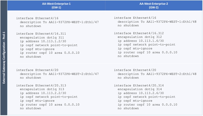
The configuration on the port-channel with 2x10GbE links that provide direct connectivity between the external gateways is provided below.
Table 15 Interface Configuration – Between External Gateways
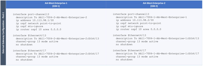
The active-active data centers leverage a Cisco Multi-Pod ACI fabric design to extend the ACI fabric and the stretched cluster across two data centers to provide business continuity in the event of a disaster. The ACI Pods can be in the same data center location or in different geographical sites. This design assumes the two Pods are in two different geographical locations that was validated in the Cisco labs using a 75km fiber spool to interconnect the data centers.
This section provides detailed procedures for setting up a Cisco ACI Multi-Pod Fabric. An Inter-Pod network is first deployed to provide connectivity between data centers, followed by an ACI fabric to provide network connectivity within the second data center. The ACI fabric deployed in this section will serve as the second Pod or site (Pod-2 or Site B in Figure 1) in the ACI Multi-Pod fabric. The two data centers will connect to the Inter-Pod network through the ACI fabric in each Pod, specifically the spine switches in Pod-1 and Pod-2. This will provide end-to-end reachability between the endpoints in the two data centers. The nodes in the HyperFlex stretched cluster that are located in both Pods will now have reachability through the Inter-Pod network.
The deployment procedures in this section assumes that the first Pod or site (single-site ACI fabric) is already running and operational. This section will focus on the second Pod or site and the inter-pod network that interconnects them.
Prerequisites
Before an ACI Multi-Pod fabric can be deployed, the ACI fabric in Pod-1 should be fully functional and running with spine switches, leaf switches and APICs.
Topology
The figure below shows the Inter-Pod network (IPN) and the connectivity from each Pod to the IPN.
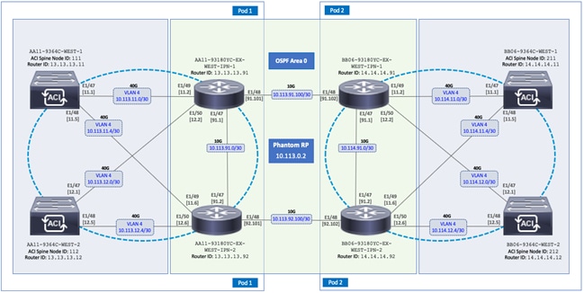
The connectivity between IPN switches use 10GbE links and 40GbE links from spine switches to the IPN in each Pod. Multiple nodes and links are used from each Pod to IPN and between IPNs to provide multiple redundant paths between Pods for load-balancing and redundancy.
Deployment Overview
A high-level overview of the steps involved in deploying an ACI Multi-Pod fabric is summarized below.
Physical Connectivity
· Complete the physical connectivity within the Inter-Pod Network (IPN) to provide connectivity between Pods or sites.
· Deploy Spine switches, Leaf switches and APIC(s) in the second ACI Pod. In this design, the third node in the 3-node APIC cluster is deployed in Pod-2. For discovery and auto-provisioning of the fabric in a new Pod, a Spine switch must have at least one link up to a Leaf switch. Spine switches will learn that a Leaf switch is connected through LLDP, which is enabled by default.
· Complete the physical connectivity to connect Spine switches to the IPN in each Pod. It is not necessary to connect all Spines in a Pod to the IPN. For redundancy, at least two Spines in each Pod should be connected to the IPN. The connected Spine switches will be seen as equal cost paths to that Pod’s TEP addresses so connecting more Spine switches to the IPN should increase the number of Equal-Cost Multi-Paths (ECMP) routes for a greater distribution of traffic load.
Deploy Inter-Pod Network (IPN)
· (Optional) Configure a VRF for ACI Multi-Pod traffic on all IPN devices and put the relevant interfaces in the VRF. This isolates the ACI Multi-Pod traffic, IP underlay and the VXLAN overlay network between the data centers. The IPN can be thought of as an extension of the ACI underlay infrastructure in each Pod. The underlay is necessary for establishing VXLAN tunnels between leaf switches and spine switches in each Pod. VXLAN tunnels enable seamless forwarding of Layer 2 and Layer 3 data plane traffic between Pods. The VXLAN overlay is essential for ensuring that the interconnected Pods function as a single ACI fabric.
· Configure Layer 2 encapsulation, Layer 2 protocols (LLDP, CDP), MTU (Jumbo) and IP addressing on relevant interfaces of the IPN devices that provide connectivity within the IPN, and between the IPN and Spines in each Pod. The Spine switches will tag all traffic towards the IPN using VLAN 4. Therefore, IPN devices must be configured for trunking using VLAN 4 on the interfaces connecting to the Spine. Enabling LLDP (preferred) or CDP on IPN interfaces is recommended for determining which ports connect to which devices. Encapsulating traffic in VXLAN adds 50 Bytes of overhead so the IPN must set to an MTU that is at least 50 Bytes higher than the MTU of the traffic being transported across VXLAN in order to prevent fragmentation. For traffic such as HyperFlex storage and vMotion traffic that use jumbo (9000 Byte) MTU, the MTU on the IPN should be the jumbo MTU plus 50 Bytes. MTU used in validation is 9216B as it is a commonly used value for jumbo MTU on many Cisco platforms.
· Enable routing within the IPN and on the connections to Spines to advertise TEP pools between Pods. Each Pod uses a unique TEP pool that must be advertised to the other Pod in order to establish VXLAN Tunnels from one Pod to the other. The Spines in each Pod that connect to the IPN also use Proxy TEP addressing that are also advertised to the other Pods. The proxy TEP addressing enables each Spine to advertise equal cost routes for the Pod subnets to the IPN routers. IPN will use the ECMP to the Spines to distribute traffic to the Pod subnets. Loopback interfaces are used on IPN nodes are used as the router-id for the routing protocol. Currently, OSPFv2 is the only routing protocol supported. Note that underlay infrastructure in an ACI Pod uses ISIS and not OSPF. If the IPN is an extensive L3 network that is already using another routing protocol, it is not necessary to use OSPF everywhere in the IPN – it is only necessary between the Spine switches and IPN devices.
· Enable IP Multicast routing using Bidirectional PIM (BIDIR-PIM) to forward Broadcast, Unknown Unicast and Multicast (BUM) traffic between Pods. This is necessary when endpoints in the same Bridge Domain are distributed across both Pods, to enable seamless East-West communication between endpoints for multi-destination or non-unicast traffic. BUM traffic is encapsulated in a VXLAN multicast frame to transport it within or between Pods. In an ACI fabric, a multicast traffic within each Bridge Domain is sent to a unique IP multicast group address. The multicast address for the bridge domain is assigned when the bridge domain is first defined in ACI. The address is allocated from a pool of multicast addresses, known as Global IP Outside (GIPo) in ACI. To forward BUM traffic between Pods, the IPN needs to support IP multicast, specifically BIDIR-PIM. In ACI Multi-Pod, when a Bridge Domain is activated within a Pod, an IGMP Join is forwarded to the IPN to receive BUM traffic from remote endpoints in the same Pod. The multicast address pool used for BUM traffic for bridge domains that span the IPN can be the same as the infrastructure GIPo range used within a Pod or different pool can be allocated for this. BIDIR-PIM requires a Rendezvous Point (RP) to be defined. For RP resiliency, a phantom RP can be used. For distributing the RP load,
· Configure DHCP Relay on IPN devices to enable auto-discovery and auto-configuration of Spines and APICs in Pod-2 from Pod-1.
Setup ACI Fabric for Multi-Pod
The following are the steps involved to set up the ACI fabric for Multi-Pod:
· Configure IP connectivity to connect Spine Interfaces to IPN devices in Pod-1.
· Configure Routing Protocols (OSPF, BGP) on the Spine Switches. OSPF will provide IP reachability between Pods, specifically between TEP address pools in each Pod. ACI Fabric will redistribute routes from IS-IS used within each Pod to OSPF and vice-versa. This effectively extends the underlay network (VRF overlay-1 in ACI Fabric) to the IPN. BGP will be used to advertise learned MAC and IP addresses of endpoints and their locations. The endpoint information is maintained on separate Counsel of Oracle Protocol (COOP) database on Spine switches on each Pod. Endpoints learned on each local Pod is advertised across the BGP-EVPN peering between Pods. The peering is directly between Spine switches in the Pods. When multiple Pods are connected across the IPN, BGP route-reflectors can be deployed in the IPN rather than direct peering between Pods.
· Configure External TEP Addresses for establishing VXLAN tunnels between data centers (across the IPN).
· Add a second Pod to the ACI fabric.
Setup Pod-2 Spine Switches, Leaf Switches, and APICs
The high-level steps involved in setting up Pod-2 spine switches, leaf switches, and APIC(s) are:
· Configure ACI Fabric access policies to enable connectivity from Pod-1 Spines switches to the IPN.
· Configure ACI Fabric Access Policies to enable connectivity from Pod-2 Spines switches to the IPN.
· Configure newly discovered Spine and Leaf switches in Pod-2 from the first Pod.
· Deploy a third APIC in Pod-2 to form a 3-node APIC cluster to manage the ACI Multi-Pod fabric.
For additional information on a Cisco ACI Multi-Pod fabric, see References section of this document and ACI product documentation.
Deployment Guidelines
The following are the deployment guidelines:
· IPN must support an MTU of 50 Bytes higher than the MTU used by the endpoints in the deployment. In this design, the HyperFlex stretched cluster that connects to the ACI Multi-Pod Fabric uses an MTU of 9000 Bytes or Jumbo frames for Storage and vMotion traffic. It is also possible for other (for example, Management, Applications) traffic in the HyperFlex cluster to use Jumbo frames. In this design, the IPN MTU is set to 9216 Bytes to keep it consistent with the Jumbo MTU on other Cisco platforms.
· ACI Multi-Pod Fabric uses a VLAN ID of 4 for connectivity between Spine Switches and IPN devices in each Pod. This is system defined and cannot be changed – the IPN devices connecting to the Spines must therefore be configured to use VLAN 4.
· IPN device must support a BIDIR-PIM range of at least /15. First generation Nexus 9000 series switches cannot be used as IPN devices as the ASICS used on these support a max BIDIR-PIM range of /24.
· For auto-discovery and auto-configuration of newly added Spine switches to work, at least one Leaf switch must be online and connected to the Spine switch in the remote Pod. The Spine switch should be able to see the Leaf switch via LLDP.
· A Multi-Pod ACI fabric deployment requires the 239.255.255.240 (System GIPo) to be configured as a BIDIR-PIM range on the IPN devices. This configuration is not required when using the Infra GIPo as System GIPo feature. The APIC and switches must be running releases that support this feature.
· Spine switches from each Pod cannot be directly connected to each other – they must go through at least one IPN router/switch.
· It is not necessary to connect all Spines switches in a Pod to the IPN. If possible, connect at least two Spine switches from each Pod to the IPN to provide node redundancy in the event of a Spine switch failure. Traffic is distributed across all the spine switches that are connected to the IPN so more spine switches can be connected to distribute the load even further.
Deploy Inter-Pod Network
This section provides the configuration for deploying the switches in the Inter-Pod network that provide connectivity between data centers. The IPN is not managed by the APIC. IPN can be thought of as an extension of the ACI fabric underlay. IPN devices must be enabled for L3 forwarding with VRF Lite (recommended), OSPF, DHCP Relay and BIDIR-PIM. LACP is also required when link bundling is deployed. LLDP is optional but recommended to verify connectivity to peers and ports used for the connection.
Deployment Overview
The high-level steps involved in the setting up the Inter-Pod Network is as follows:
· Complete the physical connectivity to connect IPN devices to Spine switches in each Pod and to remote IPN devices in the other Pod.
· Identify and collect the information required to setup the IPN.
· Configure IPN Devices in Pod-1.
· Configure IPN Devices in Pod-2.
Physical Connectivity
Figure 11 illustrates the IPN connectivity between IPN devices and to Spine switches in each Pod. The connectivity between IPN devices uses 10GbE and 40GbE to Spine switches.
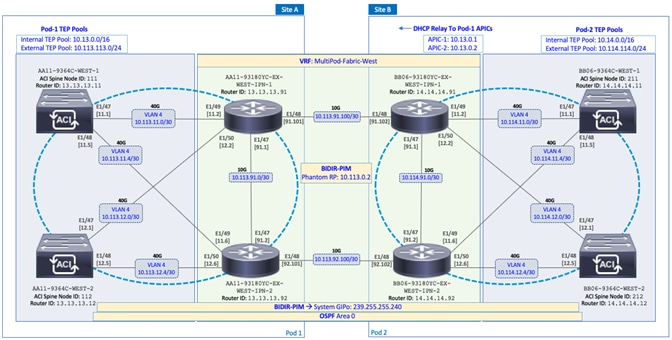
Configure IPN Devices in Pod-1
Table 16 Pod-1 IPN Configuration
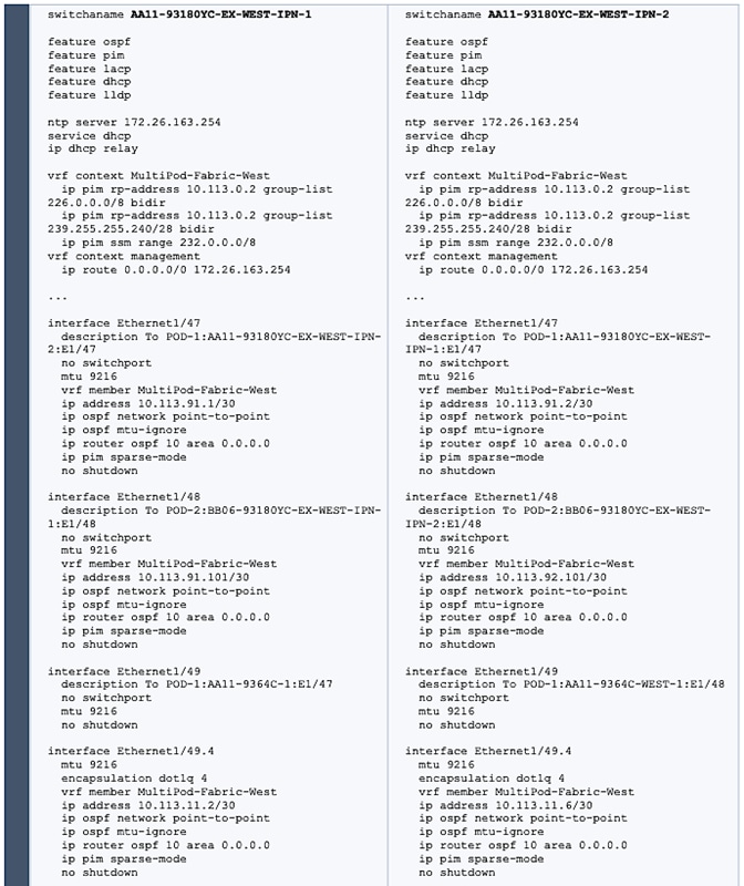
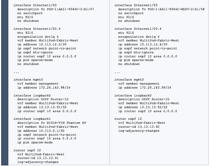
Configure IPN Devices in Pod-2
Table 17 Pod-2 IPN Configuration
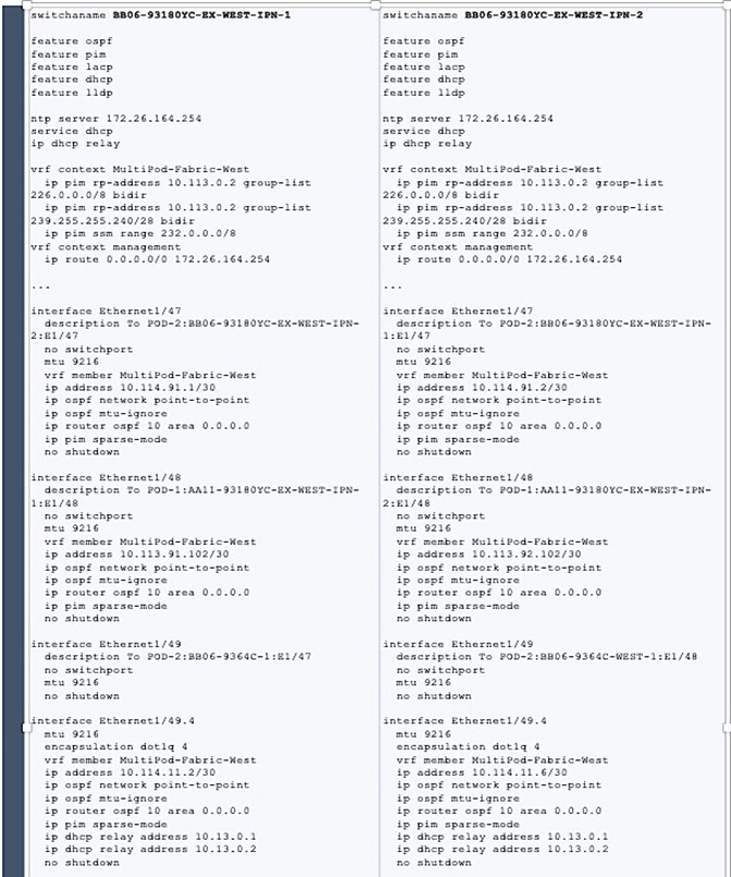
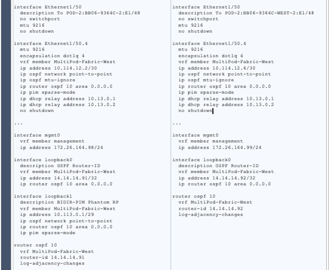
Enable Connectivity to IPN from Pod-1
The procedures in this section will enable connectivity to the inter-pod network from ACI fabric in Pod-1. In APIC Release 4.0(1) and higher, ACI provides an Add Pod configuration wizard to enable connectivity from ACI fabric (Pod-1 and Pod-2) to the inter-pod network. The wizard has changed since its initial release and the procedures outlined below is based on ACI 4.2 release.
Prerequisites
The Inter-Pod network should be setup before the ACI fabric connectivity to the inter-pod network is configured using the wizard.
Deployment Overview
The high-level steps for establishing ACI Multi-Pod fabric connectivity across the IPN is shown in the figure below. This figure is taken from the Overview section of wizard.
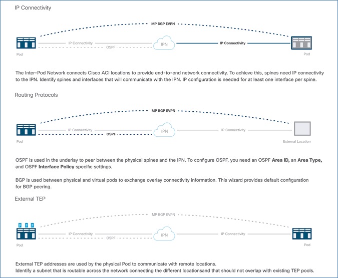
The configuration wizard is executed for each Pod in the ACI Multi-Pod fabric to enable connectivity from that Pod to the IPN. For each Pod, the wizard configures the following:
· IP Connectivity from spine switches in the Pod to the Inter-Pod network. APIC will take the information provided through the wizard to configure the necessary fabric access policies on the relevant spine switch interfaces. The access policies will include all the interface and switch policies and profiles necessary for enabling IP connectivity to the IPN.
· Routing Protocols to enable IP routing on spine switches in the Pod that connect to the IPN. This includes OSPF-based underlay network for exchanging routes between the Pods and MP-BGP based overlay network for exchanging endpoint (IP, MAC) location information using MP-BGP EVPN address families. The OSPF interface policies for the spine interfaces must be configured ahead of time.
· External TEP addressing for the Pod – this pool will be used to establish VXLAN tunnels between Pods. This pool is separate from the TEP pool used within a Pod though one can configure it to use the same pool. In this design, separate pools are used. The VXLAN tunnels enable L2 and Layer 3 forwarding between the active-active data centers.
Setup Information
This section provides the setup information for Pod-1 that the configuration wizard will use to enable connectivity to the inter-pod network from Pod-1.
IP Connectivity
The wizard configures IP connectivity on the spine switches in Pod-1 that connect to the inter-pod network. The parameters for this configuration are provided in Table 18 .
Table 18 IP Connectivity Information for Pod-1
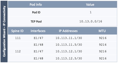
Routing Protocols
The Routing Protocols section of the wizard provides the routing protocol (OSPF, BGP) configuration on the Spine switches in Pod-1 that connect to IPN to enable the OSPF based underlay network and MP-BGP based overlay. The configuration parameters for enabling routing in Pod-1 are provided in Table 19 and Table 20 .
Table 19 OSPF Interface Policy for ACI Fabric to IPN Connectivity
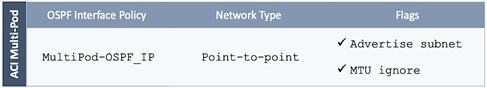
Table 20 Routing Protocols Information for Pod-1
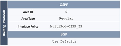
External TEP
The External TEP section of the wizard provides the address pools that Pod-1 can use for establishing VXLAN tunnels between Pods. The necessary configuration parameters for Pod-1 is provided in Table 21 .
Table 21 External TEP Information for Pod-1
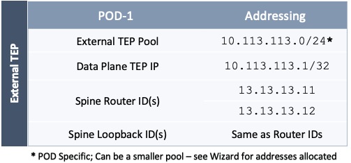
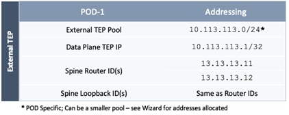
Deployment Steps
To enable IPN connectivity from Pod-1, follow these steps using the configuration wizard:
1. Use a browser to navigate to the APIC GUI. Log in using admin account.
2. From the top navigation menu, select Fabric > Inventory.
3. From the left navigation pane, expand and select Quick Start > Add Pod.
4. From the right window, click on Add Pod to run the configuration wizard.
5. In the Step 1 > Overview section of the wizard, review the provided information, collect the Setup Information from the previous section and click Get Started.
6. In the Step 2 > IP Connectivity section of the wizard, specify the Pod ID and Pod TEP Pool for Pod-1. Then for each Spine switch in Pod-1 that connects to the inter-pod network, specify the Spine ID and the interface(s) on that switch that connect to the IPN. For each interface, specify the IP Address and MTU – the MTU specified must match the MTU on the IPN switch that it connects to. To add more interfaces, click on the [+] icon to the right of the MTU field. To add more spine switches, click on the [+] icon to the right of the Spine ID.
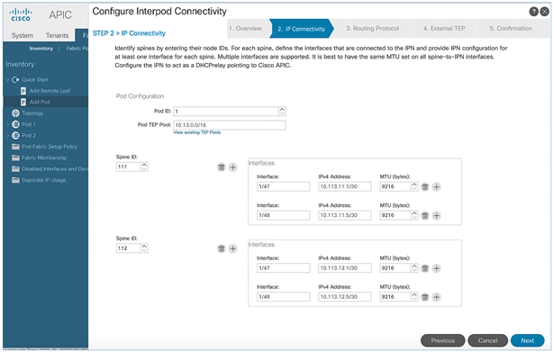
7. Click Next.
8. In the Step 3 > Routing Protocol section of the wizard, for OSPF, leave the checkbox for Use Defaults enabled and specify the Area ID, Area Type, and Interface policy. For the Interface Policy, select Create OSPF Interface Policy from the drop-down list.
9. In the Create OSPF Interface Policy pop-up window, specify a Name for the interface policy. Specify the OSPF Network Type and for interface Controls, select the checkboxes for Advertise subnet and MTU ignore.
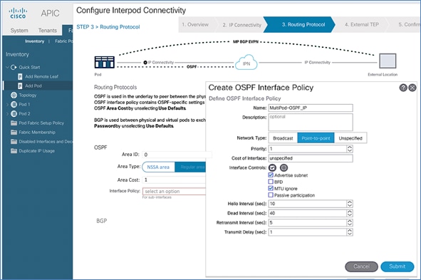
10. Click Submit to close the window.
11. For BGP, leave the Use Defaults checkbox enabled.
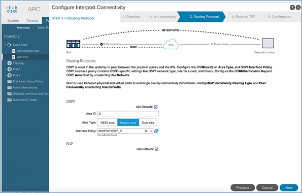
12. Click Next.
13. In Step 4 > External TEP section of the wizard, leave the checkbox Use Defaults enabled. Specify the External TEP Pool, Data Plane TEP IP and Router IDs for the spine switches in Pod-1 that connect to the IPN.
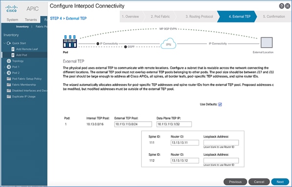
14. Click Next. In Step 5 > Confirmation section of the wizard, review the policies created by the wizard.
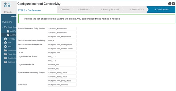
15. You will need this information for troubleshooting and to make changes if needed. For the policies and profiles that the wizard will create, you also have the option to change the naming scheme at this point.
16. Click Finish to complete the Inter-Pod connectivity for spine switches in Pod-1.
Deploy ACI Fabric in Pod-2
This section provides detailed procedures for deploying a second Pod (Pod-2) in the Cisco ACI Multi-Pod fabric. At this stage of the deployment, the first ACI fabric (Pod-1), the Inter-Pod network (non-ACI portion) and the connectivity from Pod-1 to the IPN has been deployed. In this solution, one of the APICs and half of the stretched cluster nodes connect to Pod-2.
Deployment Overview
A high-level overview of the steps involved in deploying the second ACI fabric (Pod-2) is summarized below:
· Complete the physical connectivity to connect all the devices in Pod-2. The fabric in Pod-2 should have a minimum of two Spine switches and two Leaf switches. In this design, a third APIC is also deployed in Pod-2 which will be setup at a later stage. All cabling for Pod-2, including APIC should be done at this time.
· Complete all out-of-band management connectivity for Pod-2. CIMC management connectivity to the 3rd APIC in Pod-2 should also be in place. The solution uses out-of-band management as backup though in-band management is used in this CVD release to manage the switches and APICs in the ACI fabric, and to support the Cisco Network Insights tools deployed on a Cisco Application Services Engine cluster. Only one method is needed though both are used in this solution.
· Deploy spine and leaf switches in Pod-2. The leaf switches are also border leaf switches that enable connectivity to networks outside the ACI fabric from Pod-2.
· Enable NTP, BGP Route Reflector, Pod policies, and other features necessary to bring this Pod online.
Physical Connectivity
Complete the physical cabling to bring up an ACI Fabric in Pod-1 as shown in Figure 13. The OOB management for the devices and CIMC management for the 3rd APIC (not shown below) should also be completed.
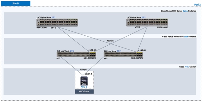
Deploy Spine and Leaf Switches in Pod-2
Once Inter-Pod connectivity is in place, Pod-2 spine and leaf switches should discoverable by the APIC(s) in the Pod-1. Once discovered, the APICs in Pod-1 will add the Pod-2 spine and leaf switches to the ACI Fabric. Follow the procedures outlined in this section to setup and deploy spine and leaf switches in Pod-2.
![]() All screenshots in this section are from a previous release of this CVD. The previous testbed environment was upgraded and re-configured for this CVD. Therefore, any screenshots showing the initial install and setup of the fabric are from the prior CVD release.
All screenshots in this section are from a previous release of this CVD. The previous testbed environment was upgraded and re-configured for this CVD. Therefore, any screenshots showing the initial install and setup of the fabric are from the prior CVD release.
Prerequisites
The prerequisites for deploying the spine and leaf switches in Pod-2 are:
· All spine and leaf switches should be running software that is compatible with the release running on the APICs. Failure to do so can impact the discovery and addition of these switches to the Fabric.
· Spine switches must be connected to at least one Leaf switch before it can be discovered. The spine switch must be able to see the leaf switch via LLDP.
· Inter-Pod network and connectivity to Pod-1 must be in place.
Deployment Overview
The high-level steps for deploying Pod-2 switches to the ACI Fabric are summarized below:
· Discover and add spine switches in Pod-2
· Discover and add leaf switches in Pod-2
· Configure Out-of-band and In-Band Management for Pod-2 switches
· Configure NTP for Pod-2 using Out-of-Band Management
· Update BGP Route Reflector Policy with Pod-2 Spine Switches
Setup Information
The setup information for deploying Spine and Leaf switches in Pod-2 are provided in the table below.
Table 22 Leaf Switches in Pod-2
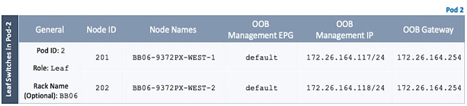
Table 23 Spine Switches in Pod-2
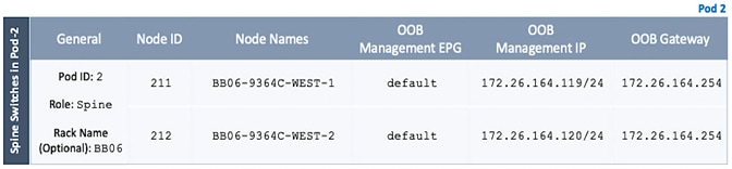
Add Pod-2 Spine Switches to the ACI Multi-Pod fabric
To discover and add Pod-2 spine switches to the ACI Multi-Pod Fabric, follow these steps:
1. Use a browser to navigate to the APIC GUI. Log in using admin account.
2. From the top menu, select Fabric > Inventory.
3. From the left navigation pane, navigate to Fabric Membership.
4. In the right navigation pane, go to the Nodes Pending Registration tab.
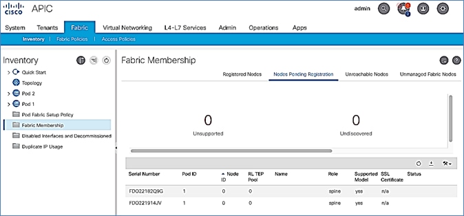
5. The newly discovered spine switches in Pod-2 will be listed with a Node ID of ‘0’. Verify that you see the two spines switches that connect to the IPN.
6. Use the serial numbers to identify the new spine switches . Collect the setup information for this switch.
7. Select the switch from the list. Right-click and select Register.
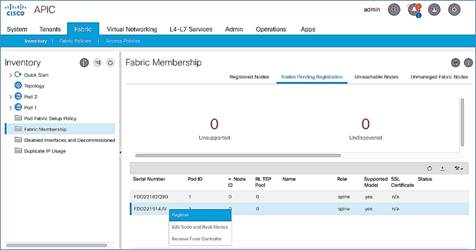
8. In the Register pop-up window, specify the Pod ID (for example, 2), Node Id (for example, 211), Node Name for example, BB06-9364C-WEST-1) and Rack Name (for example, BB06).
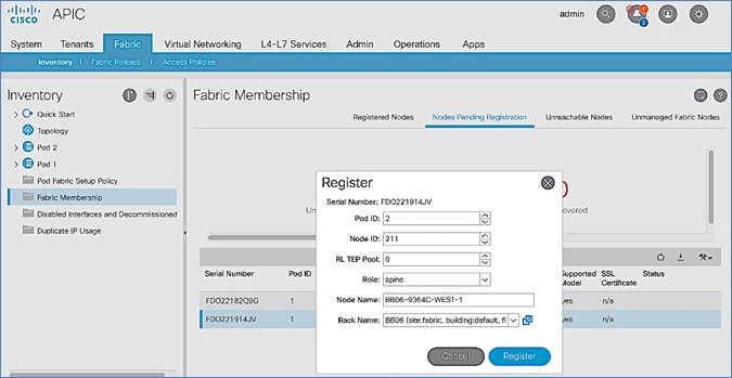
9. Click Register.
10. Switch to the Registered Nodes tab.
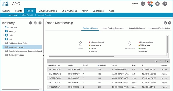
11. The newly spine switch should be in the registered list. It should transition to Active status after a few minutes.
12. In the right navigation pane, go to the Nodes Pending Registration tab.
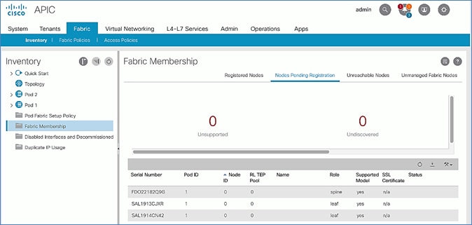
13. Select the next spine switch and repeat the above steps to register the switch. Note that you may start seeing the newly discovered leaf switches in Pod-2 – these will be added after the spine switches .
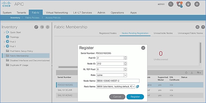
14. Both Pod-2 Spine switches will now show up under the Registered Nodes tab.
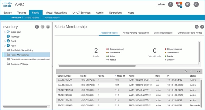
15. In the Nodes Pending Registration tab, you should now see all the leaf switches that were discovered as a result of registering the Spine switches that they connect to.
Upgrade Firmware on Spine Switches in Pod-2 (Optional)
To upgrade the firmware on the spine switches in Pod-2, follow these steps:
1. From the top menu, navigate to Admin > Firmware.
2. Select the tabs for Infrastructure > Nodes.
3. Check the Current Firmware version column for the newly deployed Spine switches to verify they are compatible with the APIC version running.
4. If an upgrade is not required, proceed to the next section but if an upgrade is required, use the product documentation to upgrade the switches.
Add Pod-2 Leaf Switches to the ACI Multi-Pod fabric
To discover and add the leaf switches in Pod-2, follow these steps:
1. Use a browser to navigate to the APIC GUI. Log in using admin account.
2. From the top menu, select Fabric > Inventory.
3. From the left navigation pane, navigate to Fabric Membership.
4. In the right navigation pane, go to the Nodes Pending Registration tab.
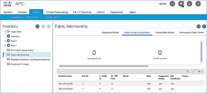
5. The newly discovered Leaf Switches will be listed with a Node ID of ‘0’. Note that the switch’s Role is leaf.
6. Use the serial numbers to identify the new Leaf switch. Collect the setup information for this switch.
7. Select the first leaf switch in the list. Right-click and select Register.
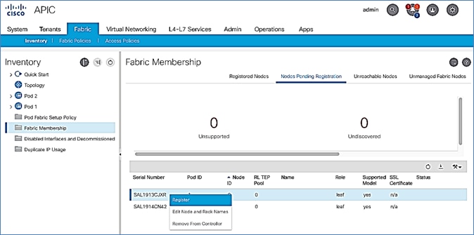
8. In the Register pop-up window, specify the Pod ID (for example, 2), Node Id (for example, 201), Node Name for example, BB06-9372PX-WEST-1) and Rack Name (for example, BB06).
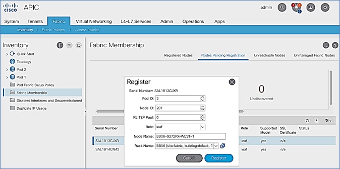
9. Click Register.
10. Switch to the Registered Nodes tab and the newly configured leaf switch should now show up in the registered list. It will transition to Active after a few minutes.
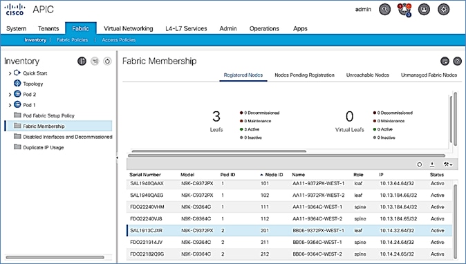
11. In the right navigation pane, click the Nodes Pending Registration tab.
12. Select the next leaf switch in the list and repeat steps 1-10 to register the switch.
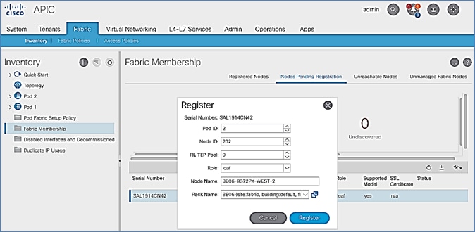
13. All registered Leaf switches will show up under the Registered Nodes tab.
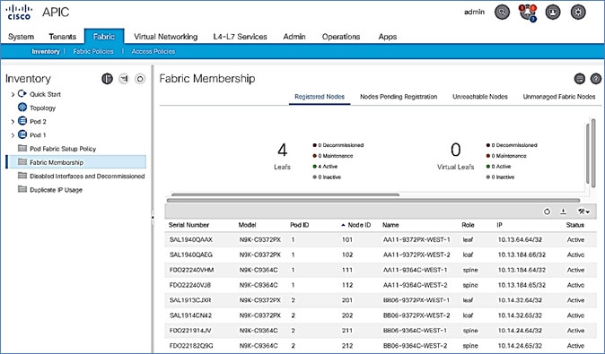
Upgrade Firmware on Leaf Switches in Pod-2 (Optional)
To upgrade the firmware on the leaf switches in Pod-2, follow these steps:
1. From the top menu, navigate to Admin > Firmware.
2. Select the tabs for Infrastructure > Nodes.
3. Check the Current Firmware version column for the newly deployed Leaf switches to verify they are compatible with the APIC version running.
4. If an upgrade is not required, proceed to the next section but if an upgrade is required, use the product documentation to upgrade the switches.
Configure Out-of-Band and In-Band Management for Pod-2 Switches
To configure out-of-band and in-band management for Pod-2 Spine and Leaf switches, follow these steps using the setup information in Table 22 and Table 23 :
1. Use a browser to navigate to the APIC GUI. Log in using admin account.
2. From the top menu, select Tenants > mgmt.
3. From the left navigation pane, expand and select Tenant mgmt > Node Management Addresses > Static Node Management Addresses.
4. Right-click and select Create Static Node Management Addresses.
5. In the Create Static Node Management Addresses pop-up window, specify a Node Range (for example, 211-212), for Config: select the box for Out-of-Band Addresses and In-Band Addresses.
6. In the Out-of-Band Addresses section of the window, for the Out-of-Band Management EPG, select default from the drop-down list.
7. Specify the Out-of-Band Management IPv4 Address for the first node in the specified node range.
8. Specify the Out-of-Band Management IPv4 Gateway.
9. In the In-Band IP Addresses section of the window, for the In-Band Management EPG, select an EPG, for e.g. In-Band_EPG or select Create In-Band Management EPG from the drop-down list to create a new EPG.
10. Specify the In-Band Management IPv4 Address for the first node in the specified node range.
11. Specify the In-Band Management IPv4 Gateway.
12. Click Submit to complete.
13. Click Yes in the Confirm pop-up window to assign the IP address to the range of nodes specified.
14. Repeat steps 1-13 for the leaf switches in Pod-2.
15. The switches can now be accessed directly using SSH.
Configure NTP for Pod-2
To configure NTP for Pod-2, follow these steps using the setup information provided below:
· NTP Policy Name: Pod2-West-NTP_Policy
· NTP Server: 172.26.164.254
· Management EPG: default (Out-of-Band)
1. Use a browser to navigate to the APIC GUI. Log in using admin account.
2. From the top menu, select Fabric > Fabric Policies.
3. From the left navigation pane, navigate to Policies > Pod > Date and Time.
4. Right-click and select Create Date and Time Policy.
5. In the Create Date and Time Policy pop-up window, specify a Name for Pod-2’s NTP Policy. Verify that the Administrative State is enabled.
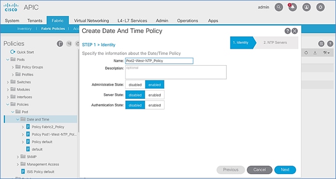
6. Click Next.
7. In Step 2 > NTP Servers, add NTP server(s) for Pod-2 using the [+] to the right of the list of servers.
8. In the Create Providers pop-up window, specify the Hostname/IP of the NTP server in the Name field. If multiple NTP Providers are being created for Pod-2, select the checkbox for Preferred when creating the preferred provider. For the Management EPG, select default (Out-of-Band) from the drop-down list.
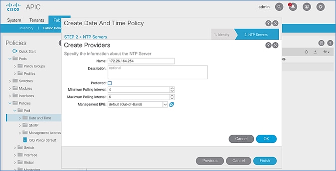
9. Click OK.
10. Click Finish.
![]() The NTP policy is not in effect until it is applied using a Pod Profile.
The NTP policy is not in effect until it is applied using a Pod Profile.
Update BGP Route Reflector Policy for Pod-2
In an ACI fabric with multiple Spine switches, a pair of Spine switches are configured as Route Reflectors (RR) to redistribute routes from external domains into the fabric. In a Multi-Pod ACI fabric, each Pod has a pair of RR nodes. This section provides enabling the RR functionality on Spine switches in Pod-2.
To enable BGP Route Reflector functionality on Spine switches in Pod-2, follow these steps using the setup information provided below:
· BGP Route-Reflector Policy Name: default
· Pod-2 Spine ID: 211,212
1. Use a browser to navigate to the APIC GUI. Log in using admin account.
2. From the top menu, select System > System Settings.
3. From the left navigation pane, navigate to BGP Route Reflector.
4. In the right windowpane, in the Route Reflector Nodes section, click the [+] on the right to Create Route Reflector Node.
5. In the Create Route Reflector Node pop-up window, for Spine Node, specify the Node ID (for example, 211) for the first Spine in Pod-2.
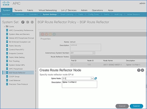
6. Click Submit.
7. Repeat steps 1-6 to add second Spine in Pod-2.
8. You should now see two Spines as Route Reflectors for each Pod in the deployment.
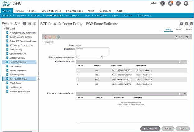
Update Pod Profile to Apply Pod Policies
In ACI, Pod Policies (for example, BGP Route Reflector policy from previous section) are applied through a Pod Profile. A separate Pod Policy Group is used to group policies for each Pod and then they are applied using the Pod Profile. In this design, different NTP servers are used in each Pod. This policy is applied to Pod-2 policy group and then applied to the Pod Profile. A single Pod Profile is used to apply Pod policies for both Pod-1 and Pod-2. This section explains how to apply Pod Policies to Pod-2.
Setup Information
· Pod Policy Group for Pod-2: Pod2-West_PPG
· Pod Selector Name for Pod-2: Pod2-West
· Pod Profile: default
· ID for Pod-2: 2
· Names of Pod Policies to be applied: Pod2-West-NTP_Policy
Deployment Steps
To apply Pod policies on Spine switches in Pod-2, follow these steps:
1. Use a browser to navigate to the APIC GUI. Log in using admin account.
2. From the top menu, select Fabric > Fabric Policies.
3. From the left navigation pane, navigate to Pods > Policy Groups.
4. Right-click and select Create Pod Policy Group, click the [+] on the right to Create Route Reflector Node.
5. In the Create Pod Policy Group pop-up window, for the Name, specify a Pod Policy Name (for example, Pod2-West_PPG). For the Date Time Policy, select the previously created NTP policy for Pod-2 (for example, Pod2-West-NTP_Policy). For the different policies, select the default policy from the drop-down list, including the BGP Route Reflector Policy that was configured in the previous section.
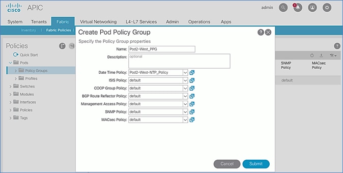
6. Click Submit.
7. From the left navigation pane, navigate to Pods > Profiles > Pod Profile default .
8. In the right windowpane, in the Pod Selectors section, click the [+] to add a Pod Selector.
9. In the newly created row, specify a Name (for example, Pod2-West). For Type, select Range. For Blocks, specify the Pod Id for Pod-2 (for example, 2). For Policy Group, select the previously created Policy Group for Pod2 (for example, Pod2-West_PPG).
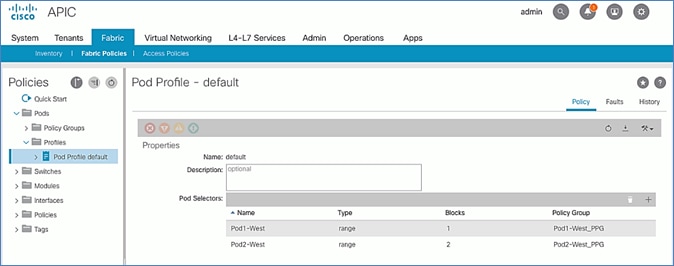
10. Click Submit to apply the Fabric Policies to Pod-2.
Enable Connectivity to IPN from Pod-2
The procedures in this section will enable connectivity to the inter-pod network from ACI fabric in Pod-2.
Setup Information
This section provides the setup information for Pod-2 that the configuration wizard will use to enable connectivity to the inter-pod network from Pod-2.
IP Connectivity
The Pod Fabric section of the wizard configures IP connectivity on the spine switches in Pod-2 that connect to the inter-pod network. The configuration parameters for enabling the IP connectivity is provided in Table 24 .
Table 24 IP Connectivity Information for Pod-2
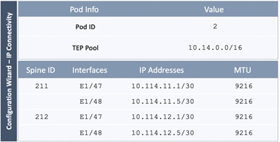
Routing Protocols
The Routing Protocols section of the wizard provides the routing protocol (OSPF, BGP) configuration on the Spine switches in Pod-2 that connect to IPN to enable the OSPF based underlay network and MP-BGP based overlay. The configuration parameters for enabling routing in Pod-2 is provided in Table 25 .
Table 25 Routing Protocols Information for Pod-2
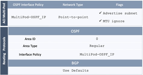
External TEP
The External TEP section of the wizard provides the address pools that Pod-2 can use for establishing VXLAN tunnels between Pods. The necessary configuration parameters for Pod-2 is provided in Table 26 .
Table 26 External TEP Information for Pod-2
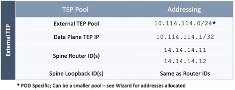
Deployment Steps
To enable IPN connectivity from Pod-2, follow these steps using the configuration wizard:
1. Use a browser to navigate to the APIC GUI. Log in using admin account.
2. From the top navigation menu, select Fabric > Inventory.
3. From the left navigation pane, expand and select Quick Start > Add Pod.
4. From the right window, click on Add Pod to run the configuration wizard.
5. In the Step 1 > Overview section of the wizard, review the provided information, collect the Setup Information from the previous section and click Get Started.
6. In the Step 2 > Pod Fabric section of the wizard, specify the Pod ID and Pod TEP Pool for Pod-2. Then for each Spine switch in Pod-2 that connects to the inter-pod network, specify the Spine ID and the interface(s) on that spine switch that connect to the IPN. For each interface, specify the IP Address and MTU that should be used. The MTU specified must match the MTU on the IPN switch that it connects to. To add more interfaces, click on the [+] icon to the right of the MTU field. To add more spine switches, click on the [+] icon to the right of the Spine ID.
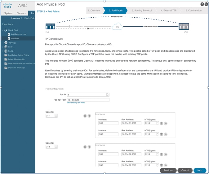
7. Click Next.
8. In the Step 3 > Routing Protocol section of the wizard, for OSPF, leave the checkbox for Use Defaults enabled and specify the Area ID, Area Type, and Interface policy. For Interface Policy, select the previously created OSPF interface policy from the drop-down list.
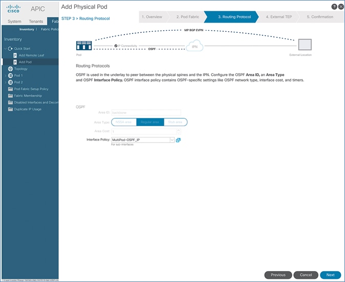
9. Click Next.
10. In Step 4 > External TEP section of the wizard, leave the checkbox Use Defaults enabled. Specify the External TEP Pool, Data Plane TEP IP and Router IDs for the spine switches in Pod-2 that connect to the IPN.
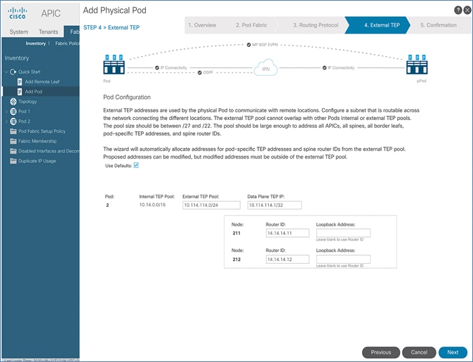
11. Click Next.
12. In Step 5 > Confirmation section of the wizard, review the policies that will be created as a result of running the wizard. You will need this information for troubleshooting and to make changes if needed. For the policies and profiles that the wizard will create, you also have the option to change the naming scheme at this point.
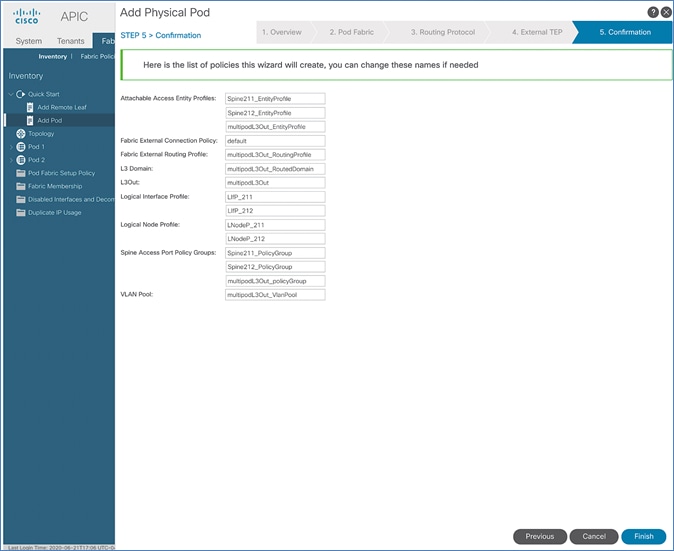
13. Click Finish to complete the Inter-Pod connectivity for spine switches in Pod-2.
Configure DHCP Relay on IPN Devices
Per the recommendations from the Configuration Wizard Summary page in previous section, add DHCP relay statements on Pod-2 IPN devices. DHCP should be relayed to Pod-1 TEP IP Addresses and should match the addresses listed on the Configuration Wizard Summary page. The configuration should be added to the Spine-facing interfaces on Pod-2 IPN devices.
This was completed in the Deploy Inter-Pod Network section but verify the APIC IP addresses and the interfaces to which it is applied.
Deploy APICs in Pod-2
This section explains the procedures for deploying an APIC (Pod-2) to the existing APIC (Pod-1) cluster. The new APIC is connected to Pod-2 Leaf switches .
![]() All screenshots in this section are from a previous release of this CVD. The previous testbed environment was upgraded and re-configured for this CVD. Therefore, any screenshots showing the initial install and setup of the APIC cluster are from the prior CVD release.
All screenshots in this section are from a previous release of this CVD. The previous testbed environment was upgraded and re-configured for this CVD. Therefore, any screenshots showing the initial install and setup of the APIC cluster are from the prior CVD release.
Prerequisites
The following are the prerequisites to deploy APICs in Pod-2:
· All Spine and Leaf switches in Pod-2 should be part of the ACI Fabric and in Active state. APIC should be redundantly connected to an Active Leaf switch pair.
· Pod-2 APIC should run a compatible server firmware version – see APIC release notes for the recommended server firmware. The server firmware version can be seen from the CIMC GUI. See the Interoperability Matrixes section for the versions used in this CVD.
· APIC in Pod-2 should run the same version of software as other APICs in the cluster APIC cluster. APIC can be upgraded after joining the cluster, but to join the cluster, the software must still be a compatible version.
Deployment Overview
The high-level steps for deploying an APIC in Pod-2 are provided below:
· Complete the initial setup of Pod-2 APIC.
· Verify that the new APIC is part of the APIC cluster
· Add Pod-2 APIC as a destination for DHCP relay on Pod-1 IPN devices.
Initial Setup of Pod-2 APIC
The procedures outlined in this section will do an initial setup and configuration of the third APIC in the APIC cluster. In this design, two APICs are deployed in Pod-1 and a third APIC in Pod-2.
Prerequisites
KVM Console access is necessary to do an initial setup and configuration of a new APIC. KVM access is available through CIMC Management and therefore access to CIMC Management on the APIC server is required.
Setup Information
The initial setup of APIC in Pod-2 requires the information provided in this section.
· CIMC Management IP Addresses
· CIMC login credentials for the APIC being setup
![]() TEP Address Pool is the APIC TEP pool and should be the same for all APICs in a cluster regardless of which Pod or site they are located in.
TEP Address Pool is the APIC TEP pool and should be the same for all APICs in a cluster regardless of which Pod or site they are located in.
![]() BD Multicast Address (GIPO) is configured only once, during the initial setup of APIC-1. APIC-1 refers to the first controller in the cluster. Remaining controllers and switches sync to the configuration on APIC-1.
BD Multicast Address (GIPO) is configured only once, during the initial setup of APIC-1. APIC-1 refers to the first controller in the cluster. Remaining controllers and switches sync to the configuration on APIC-1.
![]() APIC username and password is configured only once, during the initial setup of APIC-1 or the first controller in the cluster. Remaining controllers and switches sync to the configuration on APIC-1.
APIC username and password is configured only once, during the initial setup of APIC-1 or the first controller in the cluster. Remaining controllers and switches sync to the configuration on APIC-1.
Table 27 Setup Parameters for Pod-2 APIC
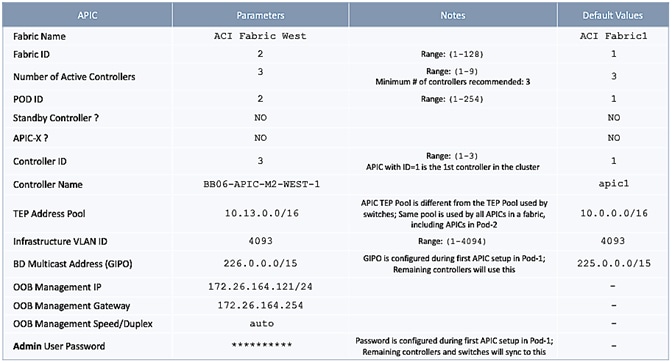
Deployment Steps
To setup a new APIC in Pod-2, follow these steps:
1. Use a browser to navigate to the CIMC IP address of the new APIC. Log in using admin account.
2. From the top menu, click Launch KVM. Select HTML based KVM from the drop-down list.
3. When the KVM Application launches, the initial APIC setup screen should be visible. Press any key to start the Setup Utility. Use the Setup information provided above to step through the initial APIC configuration below.
![]() If the APIC was previously configured, reset to factory defaults, and wipe it clean before proceeding.
If the APIC was previously configured, reset to factory defaults, and wipe it clean before proceeding.
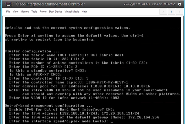
4. Press Enter to accept [auto] as the default for the last question. Review the configured information.
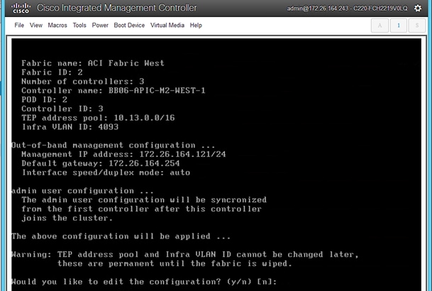
5. Click y if necessary to go back and make changes, otherwise press Enter to accept the configuration.
Verify Pod-2 APIC is Part of the APIC Cluster
To confirm that the Pod-2 APIC was successfully added to the APIC cluster, follow these steps:
1. Use a browser to navigate to the APIC GUI. Log in using admin account.
2. From the top menu, select System > Controllers.
3. From the left navigation pane, navigate to Controllers.
4. From the left navigation pane, select and expand one of the Pod-1 APICs. Navigate to Cluster as Seen by Node.
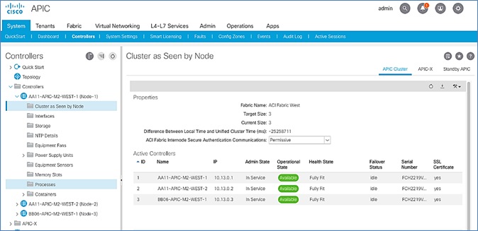
5. Verify that the newly deployed Pod-2 APIC is In Service, Available and Fully Fit as shown above.
6. Note the TEP IP Address of the newly deployed APIC (for example, 10.13.0.3). This address will be used to configure DHCP Relay on Pod-1 IPN routers to point to the new APIC. For Pod-1 APICs, DHCP relay was configured as a part of the initial IPN configuration.
Add Pod-2 APIC as DHCP Relay Destination
In this section, DHCP Relay is configured on Pod-1 IPN routers to point to the newly deployed APIC in Pod-2. DHCP Relay statements should be configured on the Spine-facing interfaces of Pod-1 IPN routers.
Setup Information
· Pod-2 APIC TEP IP Address: 10.13.0.3
Use the above information to configure DHCP relay on Pod-1 IPN routers to point to the newly deployed APIC in Pod-2.
Configure DHCP Relay for Pod-2 APIC on IPN Devices in Pod-1
| POD-1: IPN Router#1 |
POD-1: IPN Router#2 |
|
...
interface Ethernet1/49 description To POD-1:AA11-9364C-1:E1/47 no switchport mtu 9216 no shutdown
interface Ethernet1/49.4 mtu 9216 encapsulation dot1q 4 vrf member MultiPod-Fabric-West ip address 10.113.11.2/30 ip ospf network point-to-point ip ospf mtu-ignore ip router ospf 10 area 0.0.0.0 ip pim sparse-mode ip dhcp relay address 10.13.0.3 no shutdown
interface Ethernet1/50 description To POD-1:AA11-9364C-2:E1/47 no switchport mtu 9216 no shutdown
interface Ethernet1/50.4 mtu 9216 encapsulation dot1q 4 vrf member MultiPod-Fabric-West ip address 10.113.12.2/30 ip ospf network point-to-point ip ospf mtu-ignore ip router ospf 10 area 0.0.0.0 ip pim sparse-mode ip dhcp relay address 10.13.0.3 no shutdown |
...
interface Ethernet1/49 description To POD-1:AA11-9364C-WEST-1:E1/48 no switchport mtu 9216 no shutdown
interface Ethernet1/49.4 mtu 9216 encapsulation dot1q 4 vrf member MultiPod-Fabric-West ip address 10.113.11.6/30 ip ospf network point-to-point ip ospf mtu-ignore ip router ospf 10 area 0.0.0.0 ip pim sparse-mode ip dhcp relay address 10.13.0.3 no shutdown
interface Ethernet1/50 description To POD-1:AA11-9364C-WEST-2:E1/48 no switchport mtu 9216 no shutdown
interface Ethernet1/50.4 mtu 9216 encapsulation dot1q 4 vrf member MultiPod-Fabric-West ip address 10.113.12.6/30 ip ospf network point-to-point ip ospf mtu-ignore ip router ospf 10 area 0.0.0.0 ip pim sparse-mode ip dhcp relay address 10.13.0.3 no shutdown
|
Verify ACI Multi-Pod Fabric Setup
This section provides a few GUI and CLI commands that can be used to verify that the protocols are working correctly before proceeding to the next stage of the deployment.
![]() All screenshots in this section are from a previous release of this CVD. The previous testbed environment was upgraded and re-configured for this CVD.
All screenshots in this section are from a previous release of this CVD. The previous testbed environment was upgraded and re-configured for this CVD.
Verify OSPF Status on Spine Switches
OSPF is running between Spine switches and IPN devices in each Pod. To verify that OSPF is setup and working correctly between Pods, follow these steps:
1. Use a browser to navigate to the APIC GUI. Log in using admin account.
2. From the top menu, select Fabric > Inventory.
3. From the left navigation pane, select and expand Inventory > Pod 1 > (Name_of_Spine_switch_in_Pod_1) > Protocols > OSPF > OSPF for VRF-overlay-1.
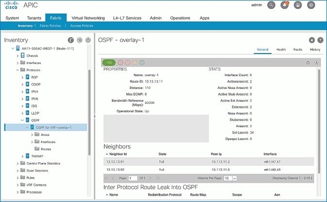
4. In the right windowpane, under the General tab, the top left icon indicates the Health for OSPF in VRF overlay-1. Confirm that the OSPF health is at 100 indicating there are no faults or errors for OSPF. Navigate to the Neighbors section and confirm for each IPN neighbor in the same Pod, neighbor state is Up and the OSPF State is Full.
5. Repeat steps 1-4 to verify OSPF on other Spine switches in the Pod that connect to the IPN.
6. You can also verify that OSPF is setup correctly by executing the following commands from CLI. SSH into the Spine switches and log in using the admin account.
- show ip ospf neighbors vrf overlay-1
- show ip ospf route vrf overlay-1
- show ip route vrf overlay-1
Verify MP-BGP EVPN Status on Spine Switches
MP-BGP sessions run between Spine switches in each Pod that connect to the IPN. To verify that MP-BGP EVPN is setup and working correctly between Pods, follow these steps:
1. Use a browser to navigate to the APIC GUI. Log in using admin account.
2. From the top menu, select Fabric > Inventory.
3. From the left navigation pane, select and expand Inventory > Pod 1 > (Name_of_Spine_switch_in_Pod_1) > Protocols > BGP > BGP for VRF-overlay-1 > Neighbors.
4. In the right windowpane, select and expand the router ID (for example, 14.14.14.11) for the peer Spines in Pod-2.
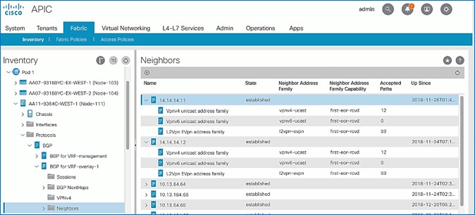
5. Verify that the State is Established and for L2Vpn EVpn address family, paths are being learned. Also confirm that the BGP health is at 100 indicating there are no faults or errors for BGP in VRF overlay-1 by navigating back to BGP for VRF-overlay-1 in the left navigation pane.
6. Repeat steps 1-5 to verify BGP on other Spine switches in the Pod that connect to the IPN.
7. You can also verify that MP-BGP EVPN is setup correctly by executing the following commands from CLI. SSH into the Spine switches and log in using the admin account.
- show bgp l2vpn evpn summary vrf overlay-1
Verify COOP Status on Spine Switches
Council of Oracles Protocol (COOP) database maintained on Spines in each Pod, is a database of all endpoints learned. This includes endpoints learned from within the Pod as well as the addresses learned through the tunnel between spine switches in different pods. The ETEP used by MP-BGP EVPN will be used by COOP to identify a remote pod's set of anycast addresses.
To verify that COOP database is learning addresses from the remote Pod, follow these steps:
1. Use a browser to navigate to the APIC GUI. Log in using admin account.
2. From the top menu, select Fabric > Inventory.
3. From the left navigation pane, select and expand Inventory > Pod 1 > (Name_of_Spine_switch_in_Pod_1) > Protocols > COOP > COOP for VRF-overlay-1.
4. In the right windowpane, under the General tab, the top left icon indicates the Health for COOP in VRF overlay-1. Confirm that the COOP health is at 100 indicating there are no faults or errors.
5. From the left navigation pane, select and expand Inventory > Pod 1 > (Name_of_Spine_switch_in_Pod_1) > Protocols > COOP > COOP for VRF-overlay-1 > Endpoint Database.
6. In the right windowpane, verify that endpoints from Pod-2 are being learned (for example, 10.1.167.168).
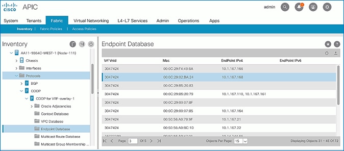
7. Double-click one endpoint to get additional details. Note that the Publisher ID is the ETEP address (for example, 10.114.114.1) of a Spine in Pod-2.
8. Repeat steps 1-7 to verify COOP on other Spine switches in the Pod that connect to the IPN.
9. You can also verify that COOP is functioning correctly by executing the following commands from CLI. SSH into the Spine switches and log in using the admin account.
- show coop internal info ip-db
The procedures outlined in this section will deploy a shared Layer 3 outside (Shared L3Out) connection in Pod-2 for reachability to networks outside the ACI fabric.
Deployment Overview
As stated earlier, the shared L3Out connection is established in the system-defined common Tenant as a common resource that can be shared by multiple tenants in the ACI fabric. Tenants must not use overlapping addresses when connecting to the outside networks using the same shared L3Out connection. The shared L3out design in Pod-2 and Pod-1 are very similar. For details on Pod-1’s L3Out design, see Solution Deployment - ACI Fabric (To Outside Networks from Pod-1) section of this document. The design and connectivity details for Pod-2 are summarized below:
· A pair of border Leaf switches in Pod-2 connect to a pair of Nexus 7000 routers outside the ACI fabric using 4 x 10GbE links. Nexus 7000 routers serve as a gateway to the networks outside the fabric.
· OSPF is used as the routing protocol to exchange routes between the ACI fabric and networks outside ACI.
· VLAN tagging is used for connectivity across the 4 links – a total of 4 VLANs for the 4 x 10GbE links. VLANs are configured on separate sub-interfaces. Each sub-interface is a separate routed link.
· Fabric Access Policies are configured on ACI Leaf switches to connect to the external routed domain or Layer 3 Outside (L3Out) using VLAN pool (vlans: 315-318).
· Pod-2 uses the same Tenant (common) and VRF (common-SharedL3Out_VRF) as Pod-1 for L3Out.
· The shared L3Out created in common Tenant “provides” an external connectivity contract that can be “consumed” from any tenant.
· The Nexus 7000s connected to Pod-2 are configured to originate and send a default route via OSPF to the border leaf switches in Pod-2.
· ACI leaf switches in Pod-2 advertise tenant subnets to Nexus 7000 switches in Pod-2.
· Host Routing – As of ACI 4.0 release and later, the ACI fabric can be enabled at the bridge-domain level to advertise host routes. In this design, host routing is used to advertise reachability to the management network for the HyperFlex stretched cluster nodes that are distributed across both Pods, but in the same IP subnet. In this solution, this enables VMware vCenter and HyperFlex Witness in a third location (outside the ACI fabric) to learn the specific Pod that a given HyperFlex node in the stretch cluster is in. This feature is critical for the operation of a HyperFlex stretch cluster in this design.
Create VLAN Pool for Shared L3Out
In this section, a VLAN pool is created to enable connectivity to networks outside the ACI fabric. The VLANs in the pool are for the individual routed links that connect the ACI border leaf switches in Pod-2 to the gateway routers outside the fabric.
Setup Information
Table 28 VLAN Pool for Shared L3Out in Pod-2
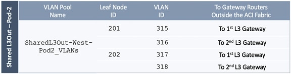
Deployment Steps
To configure a VLAN pool to connect to external gateways in Pod-2, follow these steps:
1. Use a browser to navigate to the APIC GUI. Log in using the admin account.
2. From the top navigation menu, select Fabric > Access Policies.
3. From the left navigation pane, expand and select Pools > VLAN. Right-click and select Create VLAN Pool.
4. In the Create VLAN Pool pop-up window, specify a Name and for Allocation Mode, select Static Allocation. For Encap Blocks, click on the [+] icon on the right to add VLANs to the VLAN Pool.
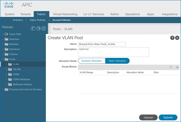
5. In the Create Ranges pop-up window, configure the VLANs for the border leaf switches that connect to external gateways outside the ACI fabric. Leave the remaining parameters as is.
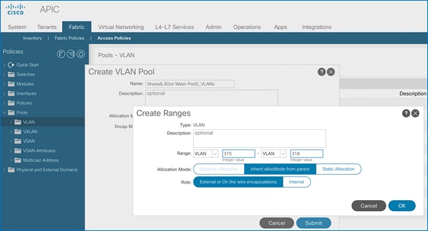
6. Click OK. Use the same VLAN ranges on the external gateway routers that connect to the ACI Fabric.
7. Click Submit to complete.
Configure Domain Type for L3Out
Follow the procedures outlined in this section to configure a domain type for the L3Out in Pod-2.
Setup Information
Table 29 Domain Type for Shared L3Out in Pod-2
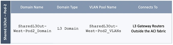
Deployment Steps
To specify the domain type for the L3Out in Pod-2, follow these steps:
1. Use a browser to navigate to the APIC GUI. Log in using the admin account.
2. From the top navigation menu, select Fabric > Access Policies.
3. From the left navigation pane, expand and select Physical and External Domains > L3 Domains.
4. Right-click on L3 Domains and select Create Layer 3 Domain.
5. In the Create Layer 3 Domain pop-up window, specify a Name for the domain. For the VLAN Pool, select the previously created VLAN pool from the drop-down list.
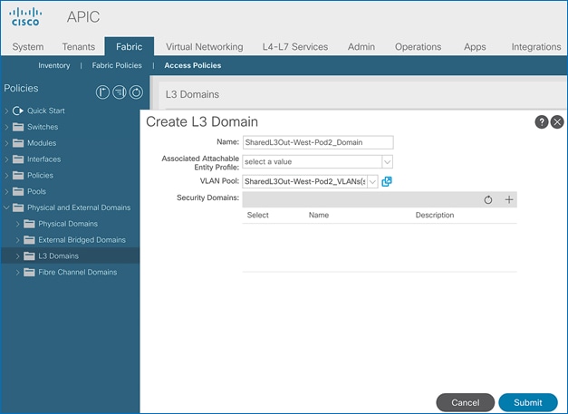
6. Click Submit to complete.
Create Attachable Access Entity Profile for L3Out
To configure an Attachable Access Entity Profile (AAEP) for the L3Out in Pod-2, follow the procedures outlined in this section.
Setup Information
Table 30 AAEP for Shared L3Out in Pod-2
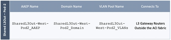
Deployment Steps
To create an AAEP for the L3Out in Pod-2, follow these steps:
1. Use a browser to navigate to the APIC GUI. Log in using the admin account.
2. From the top navigation menu, select Fabric > Access Policies.
3. From the left navigation pane, expand and select Policies > Global > Attachable Access Entity Profiles.
4. Right-click and select Create Attachable Access Entity Profile.
5. In the Create Attachable Access Entity Profile pop-up window, specify a Name. For the Domains, click on the [+] icon on the right-side of the window and select the previously created domain for the Domain Profile.
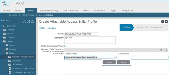
6. Click Update. You should now see the selected domain and the associated VLAN Pool.
7. Click Next. This profile is not associated with interfaces at this time.
8. Click Finish to complete.
Configure Interfaces to L3Out
Follow the procedures outlined in this section to configure interfaces to the external routed domain in Pod-2.
Setup Information
Border leaf switches (Node ID: 201,202) in Pod-2 connect to external gateways using 10Gbps links, on ports 1/47 and 1/48. The access layer setup information for this connection is provided below.
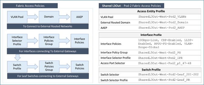
Create Interface Policy Group for L3Out Interfaces
To create an interface policy group for the L3Out in Pod-2, follow these steps:
1. Use a browser to navigate to the APIC GUI. Log in using the admin account.
2. From the top navigation menu, select Fabric > Access Policies.
3. From the left navigation pane, expand and select Interfaces > Leaf Interfaces > Policy Groups > Leaf Access Port. Right-click and select Create Leaf Access Port Policy Group.
4. In the Create Leaf Access Port Policy Group pop-up window, specify a Name and select the applicable interface policies from the drop-down list for each field.
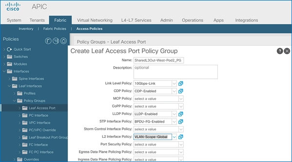
5. For the Attached Entity Profile, select the previously created AAEP to external routed domain.
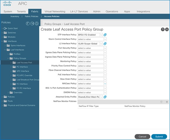
6. Click Submit to complete. You should now see the policy groups for both Pods.
Create Interface Profile for Interfaces to L3Out
To create an interface profile for the L3Out in Pod-2, follow these steps:
1. Use a browser to navigate to the APIC GUI. Log in using the admin account.
2. From the top navigation menu, select Fabric > Access Policies.
3. From the left navigation menu, expand and select Interfaces > Leaf Interfaces > Profiles. Right-click and select Create Leaf Interface Profile.
4. In the Create Leaf Interface Profile pop-up window, specify a Name. For Interface Selectors, click on the [+] icon to select access ports to apply interface policies to. In this case, the interfaces are access ports that connect Border leaf switches to gateways outside ACI.
5. In the Create Access Port Selector pop-up window, specify a selector Name. For the Interface IDs, specify the access ports connecting to the two external gateways. For the Interface Policy Group, select the previously created Policy Group from the drop-down list.
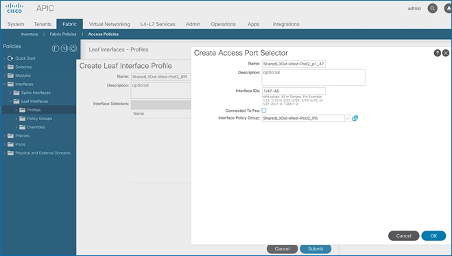
6. Click OK to complete and close the Create Access Port Selector pop-up window.
7. Click Submit to complete and close the Create Leaf Interface Profile pop-up window. You should now see the Interface profiles for both Pods.
Create Leaf Switch Profile to L3Out
To create a leaf switch profile for the L3Out in Pod-2, follow these steps:
1. Use a browser to navigate to the APIC GUI. Log in using the admin account.
2. From the top navigation menu, select Fabric > Access Policies.
3. From the left navigation menu, expand and select Switches > Leaf Switches > Profiles.
4. Right-click and select Create Leaf Profile.
5. In the Create Leaf Profile pop-up window, specify a profile Name. For Leaf Selectors, click the [+] to select the Leaf switches to apply the policies to. In this case, the Leaf switches are the border leaf switches that connect to the gateways outside ACI.
6. Under Leaf Selectors, specify a Name. For the Interface IDs, specify the access ports connecting to the two external gateways. For Blocks, select the Node IDs of the border leaf switches from the drop-down list.
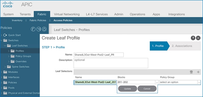
7. Click Update. Click Next.
8. In the Associations window, select the previously created Interface Selector Profiles from the list.
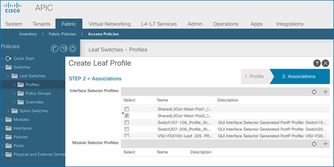
9. Click Finish to complete. You should now see the profiles for both Pods.
Configure Tenant Networking for Shared L3Out
The shared L3Out for Pod-2 is defined in the same Tenant and VRF as Pod-1. No additional configuration is therefore necessary to enable tenant Networking in Pod-2. The table below shows the tenant networking that was configured during the shared L3Out setup in Pod-1.
Table 31 Tenant Networking for Shared L3Out
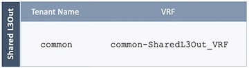
Configure OSPF Interface Policy for L3Out in Pod-2
The procedures in this section will configure OSPF interface policy for L3Out connectivity for Pod-2.
Setup Information
Table 32 OSPF Interface Policy for L3Out – Pod-2
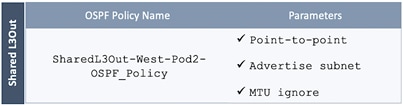
Deployment Steps
To configure OSPF interface policy for L3Out in Pod-2, follow these steps:
1. Use a browser to navigate to the APIC GUI. Log in using the admin account.
2. From the top navigation menu, select Tenants > common.
3. In the left navigation pane, select and expand common > Policies > Protocol > OSPF > OSPF Interface. Right-click and select Create OSPF Interface Policy.
4. In the Create OSPF Interface Policy pop-up window, specify a Name. For the Network Type, select Point-to-Point. For Interface Controls, select the checkboxes for Advertise subnet and MTU ignore.
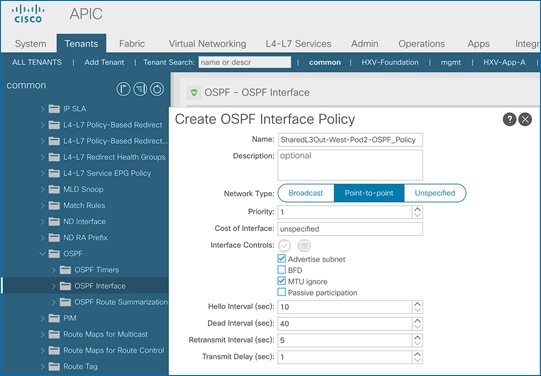
5. Click Submit.
Create Contracts for Shared L3Out in Pod-2
The contract for accessing the shared L3Out connection in Pod-2 is same as the one created for Pod-1. Therefore, a separate contract for Pod-2 does not need to be created here unless a different contract is being applied to Pod-2. The contract used for Pod-1 and Pod-2 is shown below.
Table 33 Shared L3Out Contract
Provide Contracts for Shared L3Out in Pod-2
The procedures in this section will provide the contract to access external or outside networks from Pod-2.
Setup Information
· L3Out in Pod-2: SharedL3Out-West-Pod2_RO
· External EPG in Pod-2: Default-Route
· Contract Name: Allow-Shared-L3Out (in common Tenant )
Deployment Steps
To provide contracts for accessing outside networks from Pod-2, follow these steps:
1. Use a browser to navigate to the APIC GUI. Log in using the admin account.
2. From the top navigation menu, select Tenants > common.
3. In the left navigation pane, select and expand common > Networking > L3Outs.
4. Select and expand the recently created L3Out for Pod-2.
5. Select and expand External EPGs.
6. Select the recently created L3Out EPG for Pod-2.
7. In the right windowpane, select the tab for Policy and then Contracts.
8. Under the Provided Contracts tab, click on the [+] icon on the right to add a Provided Contract.
9. For Name, select the previously created contract from the drop-down list.
10. Click Update.
11. Other Tenants can now ‘consume’ this contract to route traffic outside the ACI fabric. This deployment uses a default filter to allow all traffic.
12. Customers can modify this contract as needed to meet the needs of their environment.
Configure L3Out Connectivity for Pod-2
The procedures in this section will configure L3Out connectivity for Pod-2.
Setup Information
Table 34 L3Out Connectivity – Pod-2
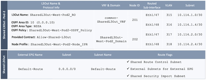
Deployment Steps
To configure L3Out connectivity to outside networks in Pod-2, follow these steps:
1. Use a browser to navigate to the APIC GUI. Log in using the admin account.
2. From the top navigation menu, select Tenants > common.
3. In the left navigation pane, select and expand common > Networking > L3Outs. Right-click and select Create L3Out.
4. In the Create L3Out pop-up window, specify a Name. Select the check box next to OSPF. Specify the OSPF Area ID (should match the external gateway configuration). For VRF, select the previously created VRF from the drop-down list. For L3 Domain, select the previously created domain for Pod-2 from the drop-down list.

5. Click Next.
6. In the Nodes and Interfaces window, uncheck the box for Use Defaults and specify a Node Profile Name(optional). For the Interface Types, select Routed Sub. Under Nodes, for the Node ID, select the first border gateway node from the drop-down list. Then configure the interfaces on this border gateway that connects to the external gateways using the setup information provided earlier. Click on the [+] icon to right of the first interface to add the second interface.
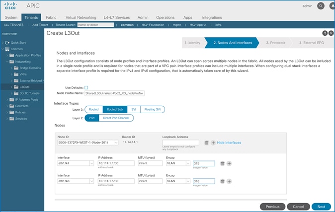
7. Click on the [+] icon to right of the first node to add the second node and click on the [+] icon to right of the first interface to add the second interface on this node.
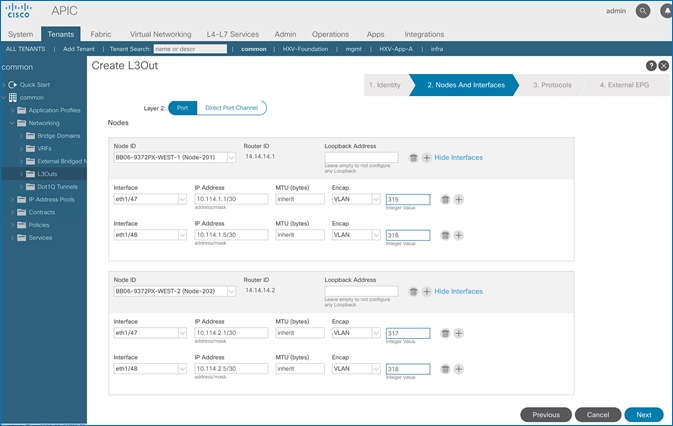
8. Click Next.
9. In the Protocols window, select the previously created OSPF interface policy from the drop-down list.
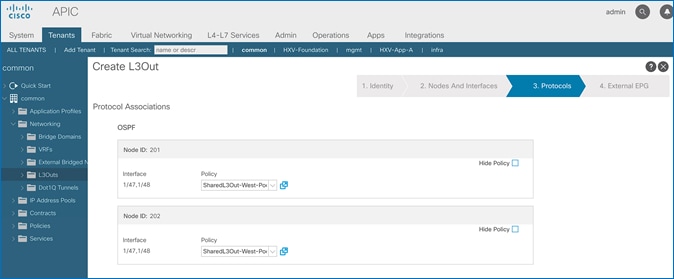
10. Click Next.
11. In the External EPG window, specify a Name (for example, Default-Route). For the Provided Contract, select the previously created contract from the drop-down list. Disable the check-box for Default EPG for all external networks.
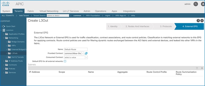
12. In the Subnets section of the window, click on the [+] icon on the right side of the window to add an external network.
13. In the Create Subnet pop-up window, for the IP Address, enter a route (for example, 0.0.0.0/0). Specify a Name (for example, Default-Route). Select the checkboxes for Shared Route Control Subnet, External Subnets for External EPG, and Shared Security Import Subnet.
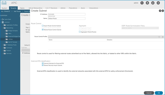
14. Click OK to complete creating the subnet.
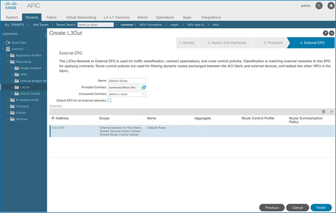
15. Click Finish to complete the L3Out connectivity in Pod-2.
Configure External Gateways in the Outside Network
This section provides a sample configuration from the Nexus switches that serve as external Layer 3 Gateways for Pod-2. The gateways are in the external network and peer with ACI border leaf switches in Pod-2 using OSPF. The gateway configuration shown below shows only the relevant portion of the configuration – it is not the complete configuration .
Enable Protocols
The protocols used between the ACI border leaf switches and external gateways have to be explicitly enabled on Nexus platforms used as external gateways in this design. The configuration to enable these protocols are provided below.
Table 35 External Gateways for Pod-2 – Protocols
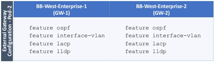
Configure OSPF
OSPF is used between the external gateways and ACI border leaf switches to exchange routing between the two domains. The global configuration for OSPF is provided below. Loopback is used as the router IDs for OSPF. Note that interfaces between ACI border leaf switches will be in OSPF Area 10.
Table 36 External Gateways for Pod-2 – Protocols
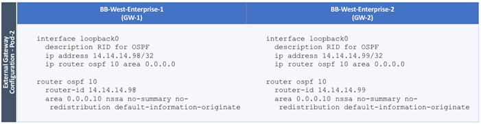
Configure Interfaces
The interface level configuration for connectivity between external gateways and ACI border leaf switches is provided below. Note that interfaces between ACI border leaf switches are in OSPF Area 10 while the loopbacks and port-channel links between the gateways are in OSPF Area 0.
Table 37 Interface Configuration – To ACI Border Leaf Switches
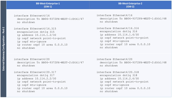
The configuration on the port-channel with 2x10GbE links that provide direct connectivity between the external gateways is provided below.
Table 38 Interface Configuration – Between External Gateways
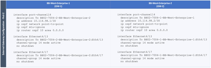
This section provides detailed procedures for configuring the ACI fabric to enable network connectivity to Cisco UCS domains in the access layer. The access layer setup will also enable connectivity for Cisco HyperFlex clusters that connect to the Cisco UCS domains in either data center (or Pod), and to the virtual machines hosted on the HyperFlex clusters.
The procedures outlined in this section are the same as that of a single-site ACI fabric except that the access layer policies apply to leaf switch pairs in either Pod. For instance, the Applications cluster (HyperFlex stretch cluster) that has nodes distributed across both data centers will connect to different leaf switch pairs but will use the same policies. ACI policies that enable access-layer connectivity are re-used when possible – customers can also define separate policies for each Cisco UCS domain but that is not the preferred option.
Deploy New Leaf Switches for Connectivity to Cisco UCS Domains
In this design, dedicated leaf switch pairs are used to connect the three Cisco UCS domains (two in Pod-1, one in Pod-2) to the ACI fabric. These leaf switches are separate from the leaf switch pair used for the shared L3Out connectivity to outside networks in each Pod.
In this section, the procedure for discovering and provisioning new leaf switch pairs in each Pod for connecting to a Cisco HyperFlex stretch cluster discussed. The leaf switches for the HyperFlex standard cluster in Pod-1 can use the same procedure.
![]() All screenshots in this section are from a previous release of this CVD. The previous testbed environment was upgraded and re-configured for this CVD. Therefore, any screenshots showing the initial install and setup of the fabric are from the prior CVD release.
All screenshots in this section are from a previous release of this CVD. The previous testbed environment was upgraded and re-configured for this CVD. Therefore, any screenshots showing the initial install and setup of the fabric are from the prior CVD release.
Topology
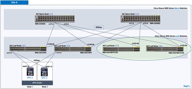
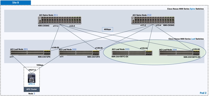
Setup Information
Table 39 Pod-1 Leaf Switches - For Connectivity to Cisco UCS and HyperFlex Domains
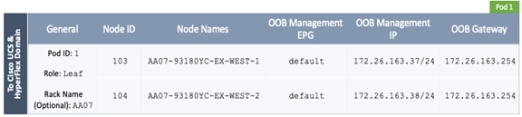
Table 40 Pod-2 Leaf Switches - For Connectivity to Cisco UCS and HyperFlex Domains
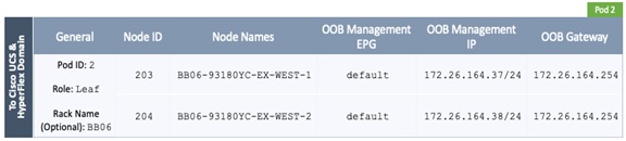
ACI Fabric Discovery of Leaf Switches
ACI automatically discovers new switches (running ACI software) connected to the ACI fabric through LLDP. To verify that the ACI fabric has discovered leaf switch pairs deployed in Pod-1 that connect to the Cisco UCS domains for HyperFlex clusters, follow these steps:
1. Use a browser to navigate to the APIC GUI. Log in using the admin account.
2. From the top menu, select Fabric > Inventory.
3. In the left navigation pane, select Fabric Membership.
4. In the right windowpane, select the Nodes Pending Registration tab. The newly discovered Leaf Switches will be listed with a Node ID of ‘0’.
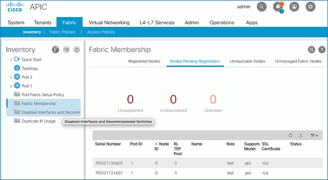
5. Note the serial numbers of the newly discovered leaf switches.
6. Determine which node will be the -1 and -2 switches in the new leaf switch pair.
7. Repeat steps 1-6 for other leaf switch pairs in Pod-1 and for Pod-2 leaf switches.
Add Nexus 9000 Series Leaf Switches to the ACI Fabric
To add the newly discovered Nexus leaf switches from the previous step, follow these steps:
1. Identify the -1 and -2 switches in the new leaf switch pair based on their physical connectivity into the fabric.
2. Determine the serial numbers corresponding to the -1 and -2 switches to map it to the ones collected in the previous step. To find the serial number for a given leaf switch, access its serial console, log in using admin account (no password) and run the command: show inventory.
3. Use a browser to navigate to the APIC GUI. Log in using the admin account.
4. From the top menu, select Fabric > Inventory.
5. In the left navigation pane, select Fabric Membership.
6. In the right windowpane, select the Nodes Pending Registration tab. From the list of switches, select the serial number corresponding to the -1 leaf. Right-click and select Register from the menu.
7. In the Register pop-up window, enter the Pod ID, Node ID, and a Node Name for the selected Leaf switch.
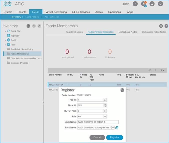
8. Click Register to complete.
9. Repeat above steps to add the second or -2 Leaf switch to the fabric.
10. Select the tab for Registered Nodes. After a few minutes, the newly added switches should transition to a Status of Active.
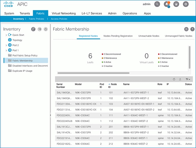
11. From the left navigation menu, navigate to the Pod (Pod 1) that the Nexus switches were added to.
12. From the right-window pane, select the Topology tab to confirm the newly added switches are part of the Pod topology.
![]()
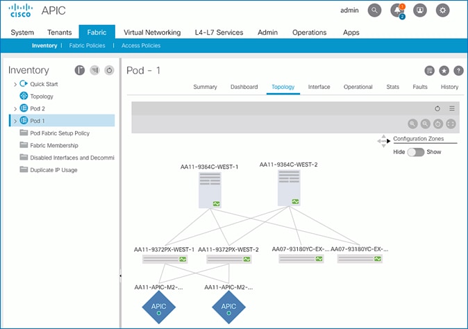
13. Repeat steps 1-12 using setup information for Pod-2 leaf switches. The same procedure can be used to discover additional leaf switch pairs in either Pod.
Setup Out-of-Band and In-Band Management for New Leaf Switches
To configure out-of-band and in-band management for the new leaf switches, follow these steps:
1. Use a browser to navigate to the APIC GUI. Log in using admin account.
2. From the top menu, select Tenants > mgmt.
3. From the left navigation pane, expand and select Tenant mgmt > Node Management Addresses > Static Node Management Addresses.
4. Right-click and select Create Static Node Management Addresses.
5. In the Create Static Node Management Addresses pop-up window, specify the Node ID Range for the switches(for example, 103-104), for Config: select the checkboxes for Out-of-Band Addresses and In-Band Addresses.
6. In the Out-of-Band Addresses section of the window, for the Out-of-Band Management EPG, select default from the drop-down list. Specify the Out-of-Band Management IPv4 Address for the first node in the specified node range. Specify the address for the Out-of-Band Management IPv4 Gateway.
7. In the In-Band IP Addresses section of the window, for the In-Band Management EPG, select an EPG, for e.g. In-Band_EPG or select Create In-Band Management EPG from the drop-down list to create a new EPG. Specify the In-Band Management IPv4 Address for the first node in the specified node range. Specify the address for the In-Band Management IPv4 Gateway.
![]() ACI will use the IP address of the first node to assign consecutive IP addresses for other nodes
ACI will use the IP address of the first node to assign consecutive IP addresses for other nodes
8. Click Submit to complete and then click Yes in the Confirm pop-up window to assign the IP address to the range of nodes specified.
9. Repeat steps 1-9 for other leaf switch pairs in Pod-1 and for the leaf switches in Pod-2.
10. The switches can now be accessed directly using SSH.
Enable Access Layer Connectivity to Cisco UCS Domains
To use the compute and storage resources provided by a Cisco HyperFlex cluster, the HyperFlex cluster must first be formed using the Cisco HyperFlex servers that are dual-homed to a pair of Cisco UCS Fabric Interconnects. The Cisco HyperFlex cluster can be deployed either:
· From the Cloud using Cisco Intersight or
· Using a HyperFlex installer virtual machine deployed in an existing virtualization environment
However, before a HyperFlex cluster can be deployed, the ACI fabric must provide connectivity from the HyperFlex installer (Intersight or Installer VM) to the HyperFlex nodes connected to Cisco UCS Fabric Interconnects in the Cisco UCS domain. ACI must also provide connectivity to any other networks and services that are required to complete the installation. To enable this connectivity, the ACI requires:
· Physical connectivity to the Cisco UCS domain, consisting of a pair of Cisco UCS Fabric Interconnects. The HyperFlex servers are dual-homed to a pair of Fabric Interconnects. A single UCS domain can support multiple HyperFlex clusters. In this design, a separate Cisco UCS domain is used for each HyperFlex cluster, and two for the HyperFlex stretched cluster. The leaf switch pairs deployed in the previous section will be used to connect the Cisco UCS domains in the solution.
· Access layer configuration or ACI Fabric Access Policies to configure the leaf switch interfaces that connect to the Cisco UCS domain.
The procedures in this section will configure the ACI fabric to connect to the Cisco UCS domains deployed in this solution. Once the physical connectivity is established between leaf switches and Cisco UCS Fabric Interconnects in the Cisco UCS domain, the links will be configured for 40GbE (for HyperFlex stretch cluster) and 10GbE (for the HyperFlex standard cluster) connectivity. Two virtual Port Channels (vPCs) will also be established from each leaf switch pair to the Cisco UCS Fabric Interconnect pair (FI-A, FI-B) in the Cisco UCS domain where the HyperFlex cluster resides. Additional policies will also be applied to the access links as needed. The corresponding UCS domain configuration is covered in an upcoming section.
Topology
The access layer connectivity from the ACI fabric to the Cisco UCS domain in Pod-1 for the HyperFlex stretched cluster is shown in Figure 17.
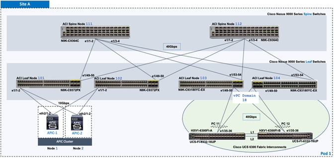
The access layer connectivity from the ACI fabric to the Cisco UCS domain in Pod-2 for the HyperFlex stretched cluster is shown in Figure 18.
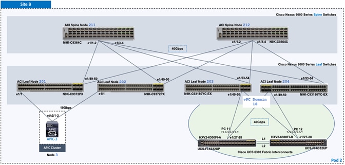
The ACI Fabric topology to connect to the Cisco UCS domain in Pod-1 for the HyperFlex standard cluster is shown in Figure 19.
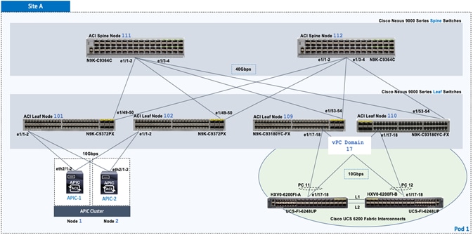
Enable 40Gbps on Links to Cisco UCS Domain
In this design, the Cisco UCS domains for the HyperFlex stretch cluster consists of a pair of Cisco UCS 6300 Series Fabric Interconnects that connect to the ACI leaf switches using 40Gbps links. 10Gbps links can also be used if needed. By default, the 40Gbps ports on the Nexus leaf switch model used in this design are Uplink ports. To re-configure these ports as Downlink ports, follow these steps:
![]() The ACI leaf switches must be reloaded for the changes in this section to take effect.
The ACI leaf switches must be reloaded for the changes in this section to take effect.
1. Use a browser to navigate to the APIC GUI. Log in using the admin account.
2. From the top navigation menu, select Fabric > Inventory.
3. From the left navigation pane, select the Pod and the first Leaf switch that connects to the UCS Domain (FI-A, FI-B).
4. In the right windowpane, select the Interface tab.
5. Under Mode, select Configuration from the drop-down list.
6. Select the port that connects to the first Fabric Interconnect (FI-A).
7. From the menu above the ports, select Downlink.
8. In the Configure Uplink/Downlink Interface pop-up window, click Submit.
9. Repeat the above steps for the port that connects to the second Fabric Interconnect (FI-B).
10. In the Configure Uplink/Downlink Interface pop-up window, click Submit and Reload Switch to reload the switch so that the changes to take effect.
11. Repeat steps 1-10 for the second Leaf switch that connects to the Cisco UCS domain (FI-A, FI-B).
12. Repeat steps 1-11 for the leaf switches that connect to UCS domain for HyperFlex stretch cluster in Pod-2.
Enable Access Layer Configuration to Cisco UCS Domain
The ACI fabric uses Fabric Access Policies (and Profiles) to configure the access layer interfaces that connect to endpoints or edge devices such as the Cisco UCS fabric interconnects in this design. The deployment workflow for configuring Fabric Access Policies on the leaf switches that connect to the Cisco UCS domains is shown in Figure 19 .
Deployment Workflow
The workflow in Figure 19 will configure the access ports on a leaf switch pair and create the vPCs to the Cisco UCS Domain (FI-A, FI-B).
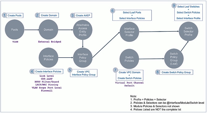
This workflow is used in the next few sections to step through the configuration required to deploy the access layer configuration on ACI leaf switches that connect to the Cisco UCS domains in this solution.
Create VLAN Pool for Cisco UCS Domain
The VLAN Pool defines all the VLANs that will be used in the Cisco UCS domain. In the ACI Fabric, the VLAN pool is created and associated with the access layer connection to the UCS domain for the HyperFlex cluster. When traffic is received from the VLANs in the pool, ACI fabric will use the VLAN tag to map it to an EPG for further forwarding decisions for traffic received on that VLAN. A single Cisco UCS domain can support multiple Cisco UCS servers and HyperFlex clusters; the VLAN pool should include the VLANs for all servers reachable through the access ports to Cisco UCS fabric Interconnects being configured.
The VLANs used in this design for the HyperFlex stretch cluster are listed in Table 41 . The corresponding VLAN names in the Cisco UCS and HyperFlex domain are also provided. The VLAN names are not used in the ACI fabric. The listed VLANs are the HyperFlex infrastructure VLANs and not VLANs for VMs hosted on the cluster - reachability to infrastructure networks are necessary for the initial setup and deployment of the HyperFlex cluster. Application VM networks are not added at this point in the configuration since the focus is on bringing up the cluster first.
Table 41 VLAN Pool – To Cisco UCS Domain and HyperFlex Cluster
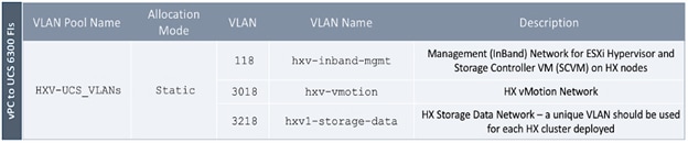
![]() In this design, the HyperFlex clusters use unique vlans for storage-data but share the management and vMotion VLANs.
In this design, the HyperFlex clusters use unique vlans for storage-data but share the management and vMotion VLANs.
To configure VLAN pools for the Cisco UCS domain and the corresponding HyperFlex cluster, follow these steps:
1. Use a browser to navigate to the APIC GUI. Log in using the admin account.
2. From the top navigation menu, select Fabric > Access Policies.
3. From the left navigation pane, expand and select Pools > VLAN. Right-click and select Create VLAN Pool.
4. In the Create VLAN Pool pop-up window, specify a Name. For Allocation Mode, select Static Allocation. For Encap Blocks, use the [+] button on the right to add VLANs to the VLAN Pool. In the Create Ranges pop-up window, configure the VLANs that need to be trunked from the Cisco UCS FIs to the ACI Fabric. Leave the remaining parameters as is. Additional VLANs can be added later as needed.
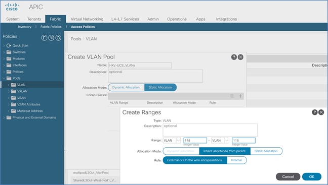
5. Repeat steps 1-4 for the remaining VLANs that need to be added to the VLAN Pool for the UCS Domain. The same VLANs need to be added to the corresponding Cisco UCS FIs in the UCS domain, on the uplinks from the FIs to the ACI fabric. For HyperFlex environment, the installation process will take care of adding this.
![]() The HX storage data VLANs should be unique (recommended) to each HyperFlex cluster. However, they should still be trunked on the uplinks to the ACI Fabric to handle failure situations where different hosts are forwarding on different Cisco UCS fabrics (FI-A, FI-B).
The HX storage data VLANs should be unique (recommended) to each HyperFlex cluster. However, they should still be trunked on the uplinks to the ACI Fabric to handle failure situations where different hosts are forwarding on different Cisco UCS fabrics (FI-A, FI-B).
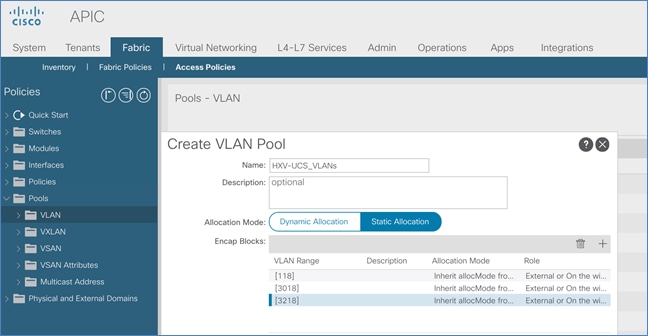
6. Click Submit to complete.
7. Repeat steps 1-6 to add the storage-data vlan (VLAN 3118) for the HyperFlex standard cluster to the same VLAN pool.
Create Domain Type for Cisco UCS Domain
Table 42 External Domain – To Cisco UCS Domain and HyperFlex Cluster
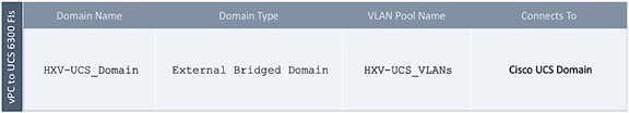
To configure the domain type for the access layer connection to the Cisco UCS domain where the HyperFlex Cluster is deployed, follow these steps:
1. Use a browser to navigate to the APIC GUI. Log in using the admin account.
2. From the top navigation menu, select Fabric > Access Policies.
3. From the left navigation pane, expand and select Physical and External Domains > External Bridged Domains.
4. Right-click External Bridged Domains and select Create Layer 2 Domain.
5. In the Create Layer 2 Domain pop-up window, specify a Name and select the previously created VLAN Pool from the drop-down list.
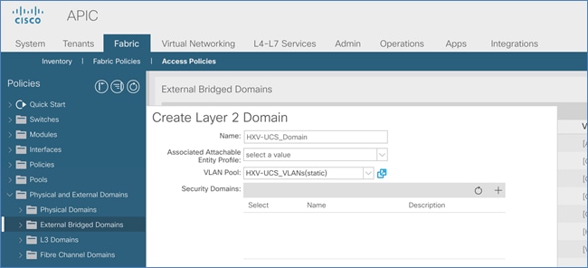
6. Click Submit to complete.
![]() In this design, the same Layer 2 domain is used for all HyperFlex UCS domains.
In this design, the same Layer 2 domain is used for all HyperFlex UCS domains.
Create Attachable Access Entity Profile for Cisco UCS Domain
Table 43 Attachable Access Entity Profile – To Cisco UCS Domain and HyperFlex Cluster
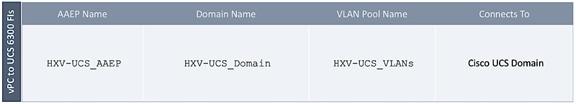
To create an Attachable Access Entity Profile (AAEP) for the access layer connection to the Cisco UCS domain where the HyperFlex cluster is deployed, follow these steps:
1. Use a browser to navigate to the APIC GUI. Log in using the admin account.
2. From the top navigation menu, select Fabric > Access Policies.
3. From the left navigation pane, expand and select Policies > Global > Attachable Access Entity Profiles.
4. Right-click and select Create Attachable Access Entity Profile.
5. In the Create Attachable Access Entity Profile pop-up window, specify a Name.
6. For the Domains, click the [+] on the right-side of the window to add a domain. For the Domain Profile, select the previously created domain from the drop-down list.
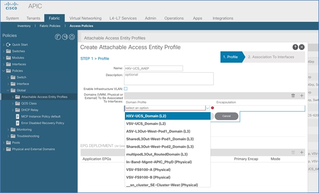
7. Click Update. Click Next. Association to interfaces will be done in a later step. Click Finish.
Create Interface Policies for the vPC Interfaces to Cisco UCS Domain
Interface policies are features or protocols that can be applied to the interfaces that connect to the UCS domain. The policies used here were pre-configured during the deployment of the ACI fabric in Pod-1. The pre-configured policies can be used for any access layer connections by grouping the policies into a policy group and applying it to the relevant interfaces. Proceed to next section to create a policy group for the UCS domain.
Table 44 Interface Policies – To Cisco UCS Domain for HyperFlex Stretched Cluster
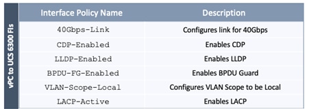
Table 45 Interface Policies – To Cisco UCS Domain for HyperFlex Standard Cluster
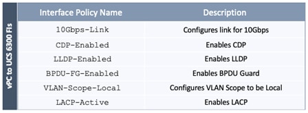
Create Interface Policy Group for the vPC Interfaces to Cisco UCS Domain
Table 46 Interface Policy Group – To Cisco UCS Domain for HyperFlex Stretched Cluster
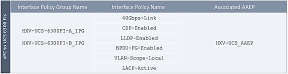
Table 47 Interface Policy Group – To Cisco UCS Domain for HyperFlex Standard Cluster
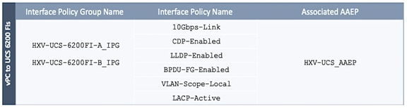
![]() Two Interface Policy Groups are necessary to create the separate vPCs to each FI in the UCS domain though interfaces to all Fabric Interconnects use the same policies in this design.
Two Interface Policy Groups are necessary to create the separate vPCs to each FI in the UCS domain though interfaces to all Fabric Interconnects use the same policies in this design.
To create an interface policy group to apply policies to the access ports that connect to the Cisco UCS domain where the HyperFlex cluster resides, follow these steps:
1. Use a browser to navigate to the APIC GUI. Log in using the admin account.
2. From the top navigation menu, select Fabric > Access Policies.
3. From the left navigation pane, expand and select Interfaces > Leaf Interfaces > Policy Groups > VPC Interface. Right-click and select Create VPC Interface Policy Group.
4. In the Create VPC Interface Policy Group pop-up window, specify a Name and select the relevant pre-configured policies for the UCS domain from the drop-down list for each field. For the Attached Entity Profile, select the previously created AAEP to Cisco UCS Domain.
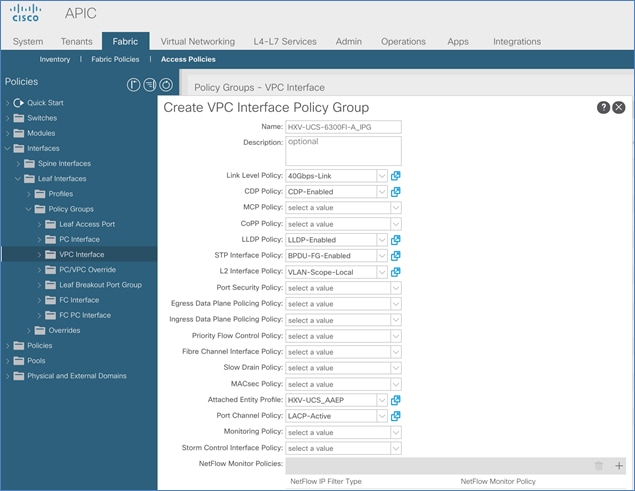
5. Click Submit to complete.
6. Repeat steps 1-5 for the vPC interface to the second Fabric Interconnect in the pair.
7. Repeat steps 1-6 for the vPCs to UCS domain (FI-A, FI-B) for HyperFlex standard cluster.
Create Leaf Interface Profile for the vPC Interfaces to Cisco UCS Domain
Table 48 Interface Profile – To Cisco UCS Domain for HyperFlex Stretched Cluster
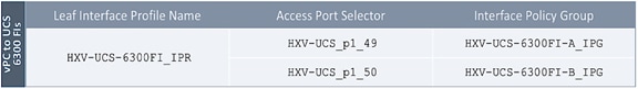
Table 49 Interface Profile – To Cisco UCS Domain for HyperFlex Standard Cluster
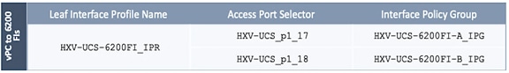
![]() Two Access Port Selectors and Interface Policy Groups are necessary to create the separate vPCs to each Fabric Interconnect in the UCS domain though the interfaces use the same interface policies in this design.
Two Access Port Selectors and Interface Policy Groups are necessary to create the separate vPCs to each Fabric Interconnect in the UCS domain though the interfaces use the same interface policies in this design.
To create a leaf interface profile to configure the access ports that connect to the Cisco UCS domain where the HyperFlex Cluster is deployed, follow these steps:
1. Use a browser to navigate to the APIC GUI. Login using the admin account.
2. From the top navigation menu, select Fabric > Access Policies.
3. From the left navigation pane, expand and select Interfaces > Leaf Interfaces > Profiles. Right-click and select Create Leaf Interface Profile.
4. In the Create Leaf Interface Profile pop-up window, specify a profile Name and for Interface Selectors, click the [+] to select access ports connecting the Leaf switches to the UCS domain. In the Create Access Port Selector pop-up window, specify a selector Name, for the Interface IDs, select the access port going from the leaf switch to the first Fabric Interconnect. For the Interface Policy Group, select the previously configured policy group from the drop-down list for the first Fabric Interconnect.

5. Click OK.
6. Repeat steps 1-5 to create a second Access Port Selector for the vPC to the second Fabric Interconnect in the Cisco UCS domain by clicking the [+] to add more Interface Selectors for the same Interface Profile.
7. Verify that all vPC interfaces to UCS have been added and are listed in the Interface Selectors section.
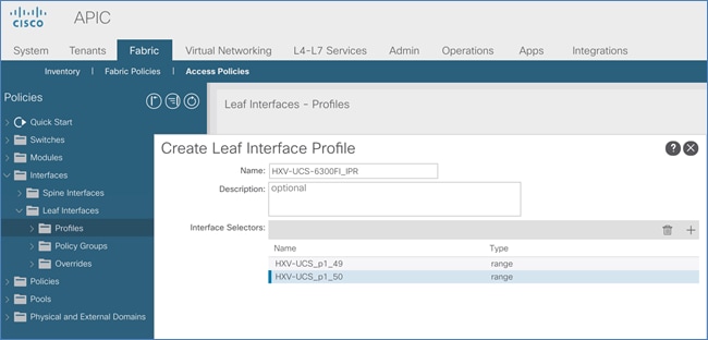
8. Click Submit to complete.
9. Repeat steps 1-8 for the interfaces going to the UCS domain for the HyperFlex standard cluster.
Create Switch Policies for the vPC Interfaces to Cisco UCS Domain
Table 50 Switch Policies – vPC to Cisco UCS Domain for HyperFlex Stretched Cluster in Pod-1
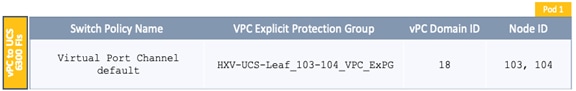
Table 51 Switch Policies – vPC to Cisco UCS Domain for HyperFlex Stretched Cluster in Pod-2
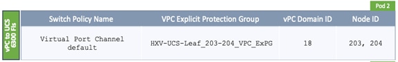
Table 52 Switch Policies – vPC to Cisco UCS Domain for HyperFlex Standard Cluster in Pod-1
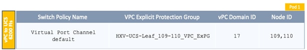
To create leaf switch policies to apply to the vPC interfaces that connect to the Cisco UCS domain where the HyperFlex Cluster is deployed, follow these steps:
1. Use a browser to navigate to the APIC GUI. Log in using the admin account.
2. From the top navigation menu, select Fabric > Access Policies.
3. From the left navigation pane, expand and select Policies > Switch > Virtual Port Channel default.
4. Right-click and select Create VPC Explicit Protection Group.
5. In the Create VPC Explicit Protection Group pop-up window, specify a Name and for the ID, provide the vPC Domain ID for the Leaf pair. For Switch 1 and Switch 2, select the Node IDs of the leaf pair from the list.
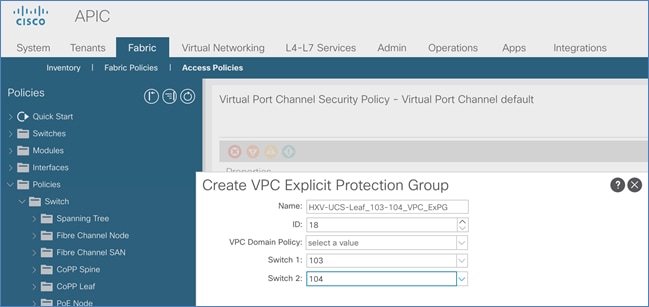
6. Click Submit to complete.
7. Repeat steps 1-6 for the leaf switches that connect to the UCS domain for the HyperFlex stretched cluster in Pod-2.
8. Repeat steps 1-6 for the leaf switches that connect to the UCS domain for the HyperFlex standard cluster in Pod-1.
Create Leaf Switch Profile
Table 53 Switch Profile – To Cisco UCS Domain for HyperFlex Stretched Cluster in Pod-1
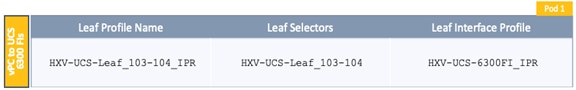
Table 54 Switch Profile – To Cisco UCS Domain for HyperFlex Stretched Cluster in Pod-2
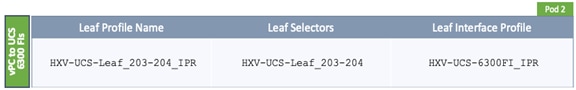
Table 55 Switch Profile – To Cisco UCS Domain for HyperFlex Standard Cluster in Pod-1
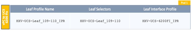
To create a switch profile to configure the leaf switches that connect to the Cisco UCS domain where the HyperFlex Cluster is deployed, follow these steps:
1. Use a browser to navigate to the APIC GUI. Log in using the admin account.
2. From the top navigation menu, select Fabric > Access Policies.
3. From the left navigation pane, expand and select Switches > Leaf Switches > Profiles. Right-click and select Create Leaf Profile.
4. In the Create Leaf Profile pop-up window, specify a profile Name. For Leaf Selectors, click the [+] on the right to select the leaf switches to apply the policies to. For Name, specify a name for the Leaf Switch Pair. For Blocks, select Node IDs for the Leaf Switch pair that connects to the Cisco UCS Domain.
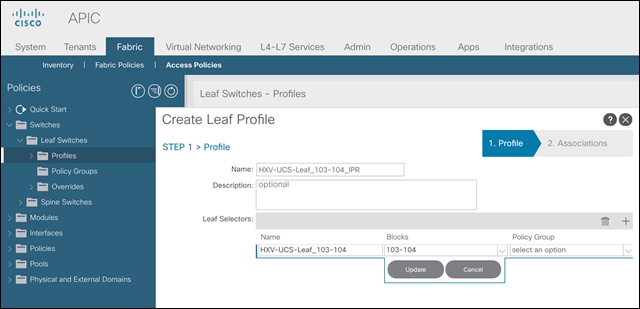
5. Click Update and then click Next.
6. In the STEP 2 > Associations window, for Interface Selector Profiles, select the previously created profile from the list.
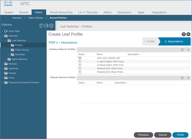
7. Click Finish to complete.
8. Repeat steps 1-7 for the leaf switches that connect to the UCS domain for the HyperFlex stretched cluster in Pod-2.
9. Repeat steps 1-7 for the leaf switches that connect to the UCS domain for the HyperFlex standard cluster in Pod-1.
Solution Deployment – Setup Cisco UCS Domains
This section covers the setup of a new Cisco UCS domain for connecting HyperFlex clusters. In this design, multiple UCS domains are used, two for the HyperFlex stretched cluster (for Applications) and one for the HyperFlex standard cluster (for Management). The same procedures are used for bringing up all three UCS domains in this design. This section also provides detailed procedures for connecting each UCS domain to Cisco Intersight.
![]() Repeat the procedures in this section for each UCS domain in the solution using the setup information provided below.
Repeat the procedures in this section for each UCS domain in the solution using the setup information provided below.
Setup Information
This section provides the setup information for deploying the three UCS domains in this solution.
Table 56 UCS Domain Setup Information
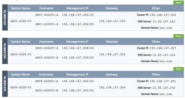
Bring Up Cisco UCS Domain with Fabric Interconnects
This section explains the setup of a new Cisco Unified Computing System (Cisco UCS) domain for use in a HyperFlex environment. The process does an initial setup of a new pair of Cisco UCS Fabric Interconnects that will be used to connect and deploy HyperFlex systems. Use the setup information to deploy the UCS domain.
Cisco UCS Fabric Interconnect A (FI-A)
To start the configuration of the FI-A, connect to the console of the fabric interconnect and step through the Basic System Configuration Dialogue:
Cisco UCS Fabric Interconnect B (FI-B)
Continue the configuration of Fabric Interconnect B (FI-B) from the console.
Initial Setup of Cisco UCS Domain
Log into Cisco UCS Manager
To log into the Cisco Unified Computing System (UCS) environment, follow these steps:
1. Use a browser to navigate to the Cluster IP of the Cisco UCS Fabric Interconnects.
2. Click the Launch UCS Manager to launch Cisco UCS Manager.
3. Click Login to log in to Cisco UCS Manager using the admin account.
4. If prompted to accept security certificates, accept as necessary.
Upgrade Cisco UCS Manager Software to Version 4.0(1c)
This document is based on Cisco UCS 4.0(1c) release of software for Cisco UCS infrastructure and HyperFlex nodes. To upgrade the Cisco UCS Manager software, the Cisco UCS Fabric Interconnect firmware and the server firmware bundles to version 4.0(1c) refer to the following Cisco UCS Manager Firmware Management Guide: https://www.cisco.com/c/en/us/td/docs/unified_computing/ucs/ucs-manager/GUI-User-Guides/Firmware-Mgmt/4-0/b_UCSM_GUI_Firmware_Management_Guide_4-0.pdf.
Configure Cisco UCS Call Home and Anonymous Reporting (Optional)
It is highly recommended by Cisco to configure Call Home in Cisco UCS Manager. Configuring Call Home will accelerate resolution of support cases. To configure Call Home, follow these steps:
To configure Call Home, follow these steps:
1. Use a browser to navigate to the UCS Manager GUI. Log in using the admin account.
2. From the left navigation pane, select the Admin icon.
3. Select All > Communication Management > Call Home.
4. In the General Tab, change the State to On.
5. Use the other tabs to set Call Home Policies and other preferences, including Anonymous Reporting which enables data to be sent to Cisco for implementing enhancements and improvements in future releases and products.
Configure NTP
To synchronize the Cisco UCS environment to the NTP servers in the Nexus switches, follow these steps:
1. Use a browser to navigate to the UCS Manager GUI. Log in using the admin account.
2. From the left navigation menu, select the Admin icon.
3. From the left navigation pane, expand and select All > Time Zone Management > Timezone.
4. In the right windowpane, for Time Zone, select the appropriate time zone from the drop-down list.
5. In the NTP Servers section, Click [+] Add to add NTP servers.
6. In the Add NTP Server pop-up window, specify the NTP server to use.
7. Click OK and Save Changes to accept.
Configure Uplink Ports on Each FI – To Nexus Leaf Switches in ACI Fabric
The Ethernet ports on Cisco UCS Fabric Interconnects can be configured in different modes depending on what is connected to them. The ports can be configured as Network Uplinks, Server ports, Appliance ports, and so on. By default, all ports are unconfigured.
To configure FI ports as network uplink ports to connect to the upstream network (in this case, ACI Fabric), follow these steps:
1. Use a browser to navigate to the Cisco UCS Manager GUI. Log in using the admin account.
2. From the left navigation menu, select the Equipment icon.
3. From the left navigation pane, expand and select All > Equipment > Fabric Interconnects > Fabric Interconnect A > Fixed Module (or Expansion Module as appropriate) > Ethernet Ports.
4. In the right windowpane, select the uplink port and right-click to select Enable to enable the port and then re-select to select Configure as Uplink Port.
5. Click Yes and OK to confirm.
6. Repeat above steps for the next uplink port that connects to the ACI fabric from the same FI.
7. Navigate to All > Equipment > Fabric Interconnects > Fabric Interconnect A > Fixed Module (or Expansion Module as appropriate) > Ethernet Ports.
8. In the right windowpane, select the uplink port and right-click to select Enable to enable the port and then re-select to select Configure as Uplink Port.
9. Click Yes and OK to confirm.
10. Repeat above steps for the next uplink port that connects to the ACI fabric from the same FI.
11. Verify that all ports are now Network ports with an Overall Status of Up.
Bundle Uplink Ports on each FI – To Nexus Leaf Switches in ACI Fabric
The uplink ports on each FI are bundled into a port-channel. The ports are connected to different Nexus Leaf switches in the ACI fabric. The leaf switches are part of a vPC domain, with a vPC to each FI – see Solution Deployment - ACI Fabric section of this document for the corresponding leaf switch configuration to this Fabric Interconnect pair.
To configure the uplink networks ports into a port-channel follow these steps on each FI:
1. Use a browser to navigate to the Cisco UCS Manager GUI. Log in using the admin account.
2. From the left navigation menu, select the LAN icon.
3. From the left navigation pane, expand and select All > LAN > LAN Cloud > Fabric A.
4. Right-click Fabric A and select Create Port Channel from the list.
5. In the Create Port Channel wizard, in the Set Port Channel Name section, for ID, specify a unique Port-Channel ID for this port-channel and for Name, specify a name for this port-channel. Click Next.
6. In the Add Ports section, select the uplink ports from the Ports table and use the >> to add them to the Ports in the port channel table to add them to port-channel. Click Finish and OK to complete.
7. Repeat steps 1-6 for Fabric B to create a port-channel to the Nexus Leaf switches, using the Fabric B uplink ports.
8. Verify the port channel is up and running on both Fabric Interconnects, with Active members.
Configuration of Server Ports – To HyperFlex Servers
The Ethernet ports on Cisco UCS Fabric Interconnects that connect to the rack-mount servers, or to the blade server chassis must be defined as server ports. When a server port comes online, a discovery process starts on the connected rack-mount server or chassis. During discovery, hardware inventories are collected, along with their current firmware revisions.
Rack-mount servers and blade chassis are automatically numbered in Cisco UCS Manager in the order which they are first discovered. For this reason, it is important to configure the server ports sequentially in the order you wish the physical servers and/or chassis to appear within Cisco UCS Manager.
Auto-Discovery of Server Ports (Option 1)
To enable servers to be discovered automatically when rack and blade servers are connected to server ports on the Cisco UCS Fabric Interconnects, follow these steps:
1. In Cisco UCS Manager, click the Equipment icon on left-navigation pane.
2. Navigate to All > Equipment. In the right windowpane, click the tab for Policies > Port Auto-Discovery Policy.
3. Under Properties, set the Auto Configure Server Port to Enabled.
4. Click Save Changes and OK to complete.
Manual Configuration of Server Ports (Option 2)
To manually define the server ports and have control over the numbering of the servers, follow these steps:
1. In Cisco UCS Manager, from the left navigation menu, click the Equipment icon.
2. Navigate to All > Equipment > Fabric Interconnects > Fabric Interconnect A > Fixed Module (or Expansion Module as appropriate) > Ethernet Ports.
3. In the right-window pane, select the first port. Right-click and select Configure as Server Port.
4. Click Yes and OK to confirm.
5. Navigate to All > Equipment > Fabric Interconnects > Fabric Interconnect A > Fixed Module (or Expansion Module as appropriate) > Ethernet Ports.
6. In the right-window pane, select the matching port from Fabric Interconnect A. Right-click and select Configure as Server Port.
7. Click Yes and OK to confirm.
8. Repeat the above steps for the remaining ports that connect to servers.
9. Verify that all ports connected to chassis, Cisco FEX and rack servers are configured as Server Ports.
Modify Chassis Discovery Policy – For Blade Servers Only (Optional)
If the Cisco HyperFlex system uses Cisco UCS server blades in a Cisco UCS 5108 blade server chassis as compute-only nodes in an extended HyperFlex cluster design, then chassis discovery policy must be configured. The Chassis Discovery policy defines the number of links between the Fabric Interconnect and the Cisco UCS Fabric Extenders on the blade server chassis. These links determine the uplink bandwidth from the chassis to FI and must be connected and active before the chassis will be discovered. The Link Grouping Preference setting specifies if the links will operate independently, or if Cisco UCS Manager will automatically combine them into port-channels. The number of links and the port types available on the Fabric Extender and Fabric Interconnect models will determine the uplink bandwidth. Cisco best practices recommends using link grouping (port-channeling). For 10 GbE connections Cisco recommends 4 links per side, and for 40 GbE connections Cisco recommends 2 links per side.
To modify the chassis discovery policy when using a Cisco UCS B-series chassis with HyperFlex, follow these steps:
1. Use a browser to navigate to the UCS Manager GUI. Log in using the admin account.
2. From the left navigation menu, select the Equipment icon.
3. From the left navigation pane, select All > Equipment.
4. In the right windowpane, click-on the Policies tab.
5. Under the Global Policies tab, set the Chassis/FEX Discovery Policy (for Action) to match the minimum number of uplink ports that are cabled between the fabric extenders on the chassis and the fabric interconnects.
6. Set the Link Grouping Preference to Port Channel.
7. Click Save Changes and OK to complete.
Enable Cisco Intersight Cloud-Based Management
Cisco Intersight can be used to centrally manage all UCS domains and servers regardless of their physical location. Cisco Intersight can also be used to install a new HyperFlex cluster connected to Fabric Interconnects in a Cisco UCS domain. However, Cisco Intersight currently does not support the install of HyperFlex stretched clusters. Therefore, in this design, all Cisco UCS domains and HyperFlex systems are managed from Cisco Intersight but only the management HyperFlex cluster is installed using Cisco Intersight.
In this section, you will connect a Cisco UCS domain to Cisco Intersight to enable cloud-based management of the environment. This procedure is followed for all Cisco UCS domains in the design. The installation of a standard HyperFlex cluster using Cisco Intersight is covered in the next section.
Prerequisites
The prerequisites for setting up access to Cisco Intersight are as follows.
· An account on cisco.com.
· A valid Cisco Intersight account. This can be created by navigating to https://intersight.com and following the instructions for creating an account. The account creation requires at least one device to be registered in Intersight and requires Device ID and Claim ID information from the device. See Collecting Information From Cisco UCS Domain for an example of how to get Device ID and Claim ID from Cisco UCS Fabric Interconnect devices.
· Valid License on Cisco Intersight – see Cisco Intersight Licensing section below for more information.
· Cisco UCS Fabric Interconnects must have access to Cisco Intersight. In this design, the reachability is through an out-of-band network in the existing infrastructure, and not through the Cisco ACI Multi-Pod fabric.
· Cisco UCS Fabric Interconnects must be able to do a DNS lookup to access Cisco Intersight.
· Device Connectors on Fabric Interconnects must be able to resolve svc.ucs-connect.com.
· Allow outbound HTTPS connections (port 443) initiated from the Device Connectors on Fabric Interconnects to Cisco Intersight. HTTP Proxy is supported.
Cisco Intersight Licensing
Cisco Intersight is offered in two editions:
· Base license which is free to use, and offers a large variety of monitoring, inventory, and reporting features.
· Essentials license, at an added cost but provides advanced monitoring, server policy and profile configuration, firmware management, virtual KVM features, and more. A 90-day trial of the Essentials license is available for use as an evaluation period.
New features and capabilities will be added to the different licensing tiers over time.
Setup Information
To setup access to Cisco Intersight, the following information must be collected from the Cisco UCS Domain. The deployment steps below will show how to collect this information.
· Device ID
· Claim Code
Deployment Steps
To setup access to Cisco Intersight from a Cisco UCS domain, follow these steps:
Connect to Cisco Intersight
To connect and access Cisco Intersight, follow these steps:
1. Use a web browser to navigate to Cisco Intersight at https://intersight.com/.
2. Log in with a valid cisco.com account or single sign-on using your corporate authentication.
Collect Information from Cisco UCS Domain
To collect information from Cisco UCS Fabric Interconnects to setup access to Cisco Intersight, follow these steps:
1. Use a web browser to navigate to the Cisco UCS Manager GUI. Log in using the admin account.
2. From the left navigation menu, select the Admin icon.
3. From the left navigation pane, select All > Device Connector.
4. In the right windowpane, for Intersight Management, click Enabled to enable Intersight management.
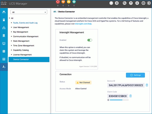
5. From the Connection section, copy the Device ID and Claim ID information. This information will be required to add this device to Cisco Intersight.
6. (Optional) Click Settings to change Access Mode and to configure HTTPS Proxy.
Add Cisco UCS Domain to Cisco Intersight
To add Cisco UCS Fabric Interconnects to Cisco Intersight to manage the UCS domain, follow these steps:
1. From Cisco Intersight, in the left navigation menu, select Devices.
2. Click the Claim a New Device button in the top right-hand corner.
3. In the Claim a New Device pop-up window, paste the Device ID and Claim Code collected in the previous section.
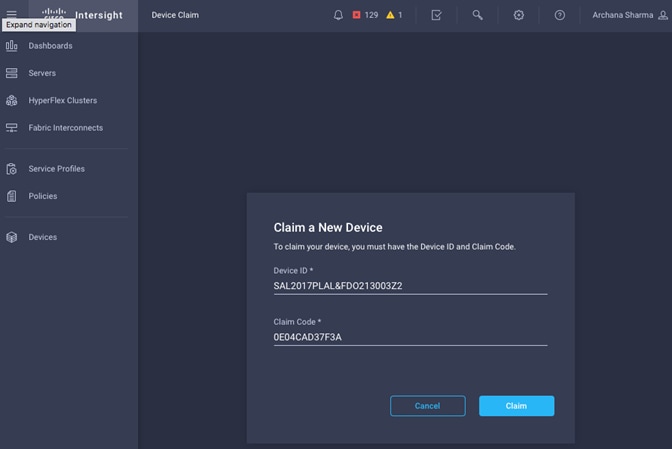
4. Click Claim.
5. On Cisco Intersight, the newly added UCS domain should now have a Status of Connected.
6. On Cisco UCS Manager, the Device Connector should now have a Status of Claimed.
Add Additional Cisco UCS Domains and Servers to Cisco Intersight
Repeat the procedures in the previous sub-sections to add more UCS domains and servers to Cisco Intersight. The UCS domains in this design that are managed by Cisco Intersight are shown below.
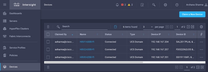
In this section, you will create the foundational infrastructure within ACI that will provide the necessary connectivity to the UCS domains and HyperFlex systems in each Pod. This connectivity must be in place before the initial install and deployment of a HyperFlex cluster. The foundation infrastructure provides the following:
· In-Band Management connectivity to all ESXi hosts and HyperFlex storage controller VMs in the cluster. This is required to manage the ESXi hosts in the cluster from VMware vCenter and for the overall management and operation of the cluster itself. This connectivity is also required for the initial install and deployment of the HyperFlex clusters.
· vMotion connectivity across the ACI fabric for HyperFlex clusters. vMotion is optional but it is foundational network and therefore it is configured along with other HyperFlex infrastructure networks
· Storage data connectivity for both HyperFlex clusters. This includes ESXi hosts accessing datastores on cluster but also for storage traffic between nodes in the cluster. This connectivity is configured in later section.
Create Foundation Tenant and VRF
To enable HyperFlex foundational infrastructure connectivity, follow the procedures outlined in this section to create a tenant and VRF as a container for handling all forwarding for this type of traffic through the ACI fabric. The same Tenant and VRF will be used by all HyperFlex clusters that connect to this ACI Multi-Pod fabric.
Setup Information
· Tenant: HXV-Foundation
· VRF: HXV-Foundation_VRF
Deployment Steps
1. Use a browser to navigate to the APIC GUI. Log in using the admin account.
2. From the top navigation menu, select Tenants > Add Tenant.
3. In the Create Tenant pop-up window, specify a Name for the tenant. For the VRF Name, enter a name for the only VRF in this Tenant Check the box for “Take me to this tenant when I click finish.” (Optional)
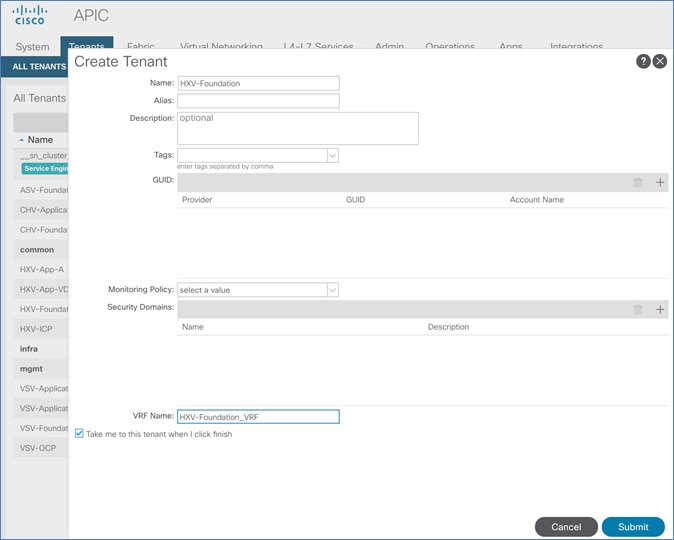
4. Click Submit to complete.
Configure ACI Fabric for HyperFlex In-Band Management
Follow the procedures outlined in this section to enable forwarding of HyperFlex in-band management traffic through the ACI fabric.
Create Bridge Domain for In-Band Management
To create a Bridge Domain for HyperFlex in-band management, follow these steps:
Setup Information
· Tenant: HXV-Foundation
· VRF: HXV-Foundation_VRF
· Bridge Domain: HXV-IB-MGMT_BD
Deployment Steps
1. Use a browser to navigate to the APIC GUI. Log in using the admin account.
2. From the top navigation menu, select Tenants > HXV-Foundation. If you do not see this tenant in the top navigation menu, select Tenants > ALL TENANTS and double-click on HXV-Foundation.
3. From the left navigation pane, expand and select Tenant HXV-Foundation > Networking > Bridge Domains. Right-click and select Create Bridge Domain.
4. In the Create Bridge Domain wizard, for Name, specify a name for the bridge domain. Enable the checkbox for Advertise Host Routes. For VRF, select the previously created VRF from the drop-down list. For Forwarding, select Custom from the drop-down list. For L2 Unknown Unicast, select Flood from the drop-down list. The checkbox for ARP Flooding should now show up and be enabled.
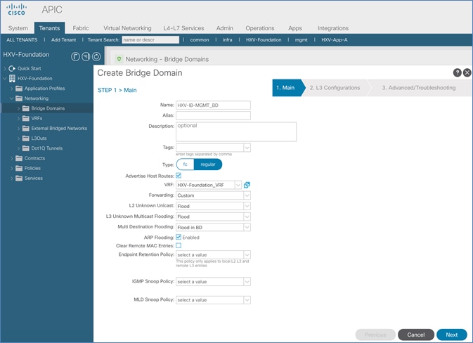
5. Click Next.
6. In the L3 Configurations section, for EP Move Detection Mode, select the checkbox to enable GARP based detection. See the Review/Enable ACI Fabric Settings section for more details. Leave other settings as is.

7. Click Next. Skip the Advanced/Troubleshooting section. Click Finish to complete.
Configure Subnet Gateway for In-Band Management
To configure a gateway for in-band management, follow these steps:
Setup Information
· Tenant: HXV-Foundation
· Bridge Domain: HXV-IB-MGMT_BD
· BD Subnet: 10.1.167.254
Deployment Steps
1. Use a browser to navigate to the APIC GUI. Log in using the admin account.
2. From the top navigation menu, select Tenants > HXV-Foundation. If you do not see this tenant in the top navigation menu, select Tenants > ALL TENANTS and double-click HXV-Foundation.
3. From the left navigation pane, select and expand Tenant HXV-Foundation > Networking > Bridge Domains > HXV-IB-MGMT_BD. Right-click and select Create Subnet.
4. In the Create Subnet pop-up window, specify the Default Gateway IP and for Scope, select Advertised Externally and Shared between VRFs. Leave everything else as is.
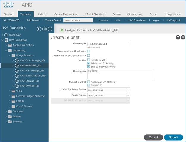
5. Click Submit.
Create Application Profile for In-Band Management
To create an application profile for in-band management, follow these steps:
Setup Information
· Tenant: HXV-Foundation
· Application Profile: HXV-IB-MGMT_AP
Deployment Steps
1. Use a browser to navigate to the APIC GUI. Log in using the admin account.
2. From the top navigation menu, select Tenants > HXV-Foundation. If you do not see this tenant in the top navigation menu, select Tenants > ALL TENANTS and double-click on HXV-Foundation.
3. From the left navigation pane, right-click Tenant HXV-Foundation and select Create Application Profile.
4. In the Create Application Profile pop-up window, specify a Name for the Application Profile.
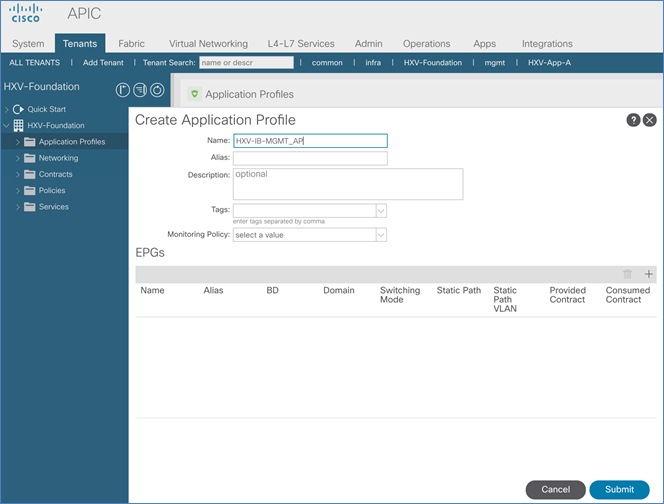
5. Click Submit to complete
Create EPG for In-Band Management
To create an EPG for in-band management, follow these steps:
Setup Information
· Tenant: HXV-Foundation
· Application Profile: HXV-IB-MGMT_AP
· Bridge Domain: HXV-IB-MGMT_BD
· EPG: HXV-IB-MGMT_EPG
Deployment Steps
1. Use a browser to navigate to the APIC GUI. Log in using the admin account.
2. From the top navigation menu, select Tenants > HXV-Foundation. If you do not see this tenant in the top navigation menu, select Tenants > ALL TENANTS and double-click on HXV-Foundation.
3. From the left navigation pane, select and expand Tenant HXV-Foundation > Application Profiles > HXV-IB-MGMT_AP. Right-click and select Create Application EPG.
4. In the Create Application EPG pop-up window, specify a Name for the EPG. For Bridge Domain, select the previously created Bridge Domain.
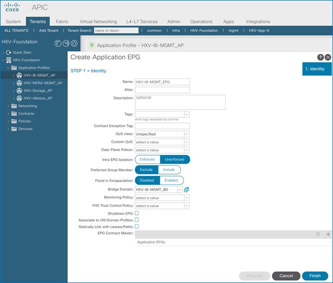
5. Click Finish.
Associate EPG with UCS Domain
To associate the In-Band Management EPG with UCS Domain, follow these steps using the setup information provided below:
Setup Information
· Tenant: HXV-Foundation
· Application Profile: HXV-IB-MGMT_AP
· Bridge Domain: HXV-IB-MGMT_BD
· EPG: HXV-IB-MGMT_EPG
· Domain: HXV-UCS_Domain
Deployment Steps
1. Use a browser to navigate to the APIC GUI. Log in using the admin account.
2. From the top navigation menu, select Tenants > HXV-Foundation. If you do not see this tenant in the top navigation menu, select Tenants > ALL TENANTS and double-click on HXV-Foundation.
3. From the left navigation pane, select and expand Tenant HXV-Foundation > Application Profiles > HXV-IB-MGMT_AP > Application EPGs > HXV-IB-MGMT_EPG. Right-click and select Add L2 External Domain Association.
4. In the Add L2 External Domain Association pop-up window, select the previously created domain.
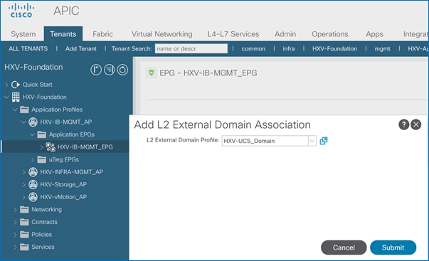
5. Click Submit.
Add Contract to Access Outside Networks and Services
To enable access to network and services outside the ACI fabric through the Shared L3Out in the common Tenant, follow these steps:
Setup Information
· Tenant: HXV-Foundation
· Application Profile: HXV-IB-MGMT_AP
· EPG: HXV-IB-MGMT_EPG
· Contract: Allow-Shared-L3Out
Deployment Steps
1. Use a browser to navigate to the APIC GUI. Log in using the admin account.
2. From the top navigation menu, select Tenants > HXV-Foundation. If you do not see this tenant in the top navigation menu, select Tenants > ALL TENANTS and double-click on HXV-Foundation.
3. From the left navigation pane, select and expand Tenant HXV-Foundation > Application Profiles > HXV-IB-MGMT_AP > Application EPGs > HXV-IB-MGMT_EPG. Right-click and select Add Consumed Contract.
4. In the Add Consumed Contract pop-up window, select the Allow-Shared-L3Out contract from the drop-down list.
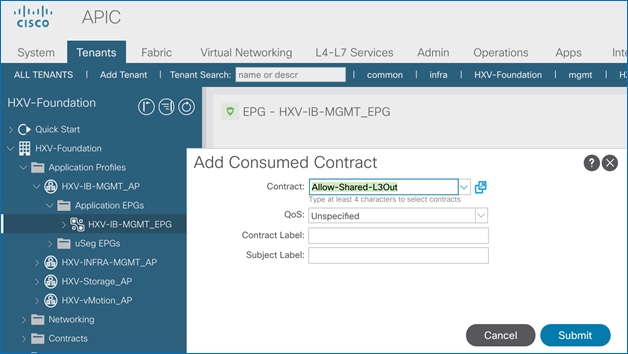
5. Click Submit.
Configure ACI Fabric for HyperFlex vMotion Traffic
Follow the procedures outlined in this section to enable forwarding of HyperFlex vMotion traffic through the fabric.
Create Bridge Domain for HyperFlex vMotion Traffic
To create a Bridge Domain for HyperFlex vMotion traffic, follow these steps:
Setup Information
· Tenant: HXV-Foundation
· VRF: HXV-Foundation_VRF
· Bridge Domain: HXV-vMotion_BD
Deployment Steps
1. Use a browser to navigate to the APIC GUI. Log in using the admin account.
2. From the top navigation menu, select Tenants > HXV-Foundation. If you do not see this tenant in the top navigation menu, select Tenants > ALL TENANTS and double-click on HXV-Foundation.
3. From the left navigation pane, expand and select Tenant HXV-Foundation > Networking > Bridge Domains. Right-click and select Create Bridge Domain.
4. In the Create Bridge Domain wizard, specify a Name for the bridge domain. For VRF, select the previously created VRF from the drop-down list. For Forwarding, select Custom from the drop-down list. For L2 Unknown Unicast, select Flood from the drop-down list. The checkbox for ARP Flooding should now show up as enabled.
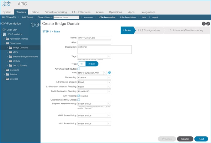
5. Click Next.
6. In the L3 Configurations section, for EP Move Detection Mode, select the checkbox to enable GARP based detection if needed. See Review/Enable ACI Fabric Settings section for more details on when to enable this feature. Leave all other settings as is.
7. Click Next. Skip the Advanced/Troubleshooting section. Click Finish to complete.
Configure Subnet Gateway for HyperFlex vMotion Traffic
To configure a gateway for the vMotion traffic, follow these steps:
Setup Information
· Tenant: HXV-Foundation
· Bridge Domain: HXV-vMotion_BD
· BD Subnet: 172.0.167.254
Deployment Steps
1. Use a browser to navigate to the APIC GUI. Log in using the admin account.
2. From the top navigation menu, select Tenants > HXV-Foundation. If you do not see this tenant in the top navigation menu, select Tenants > ALL TENANTS and double-click on HXV-Foundation.
3. From the left navigation pane, select and expand Tenant HXV-Foundation > Networking > Bridge Domains > HXV-vMotion_BD. Right-click and select Create Subnet.
4. In the Create Subnet pop-up window, specify the Default Gateway IP and for Scope, select Advertised Externally and Shared between VRFs. Leave everything else as is.
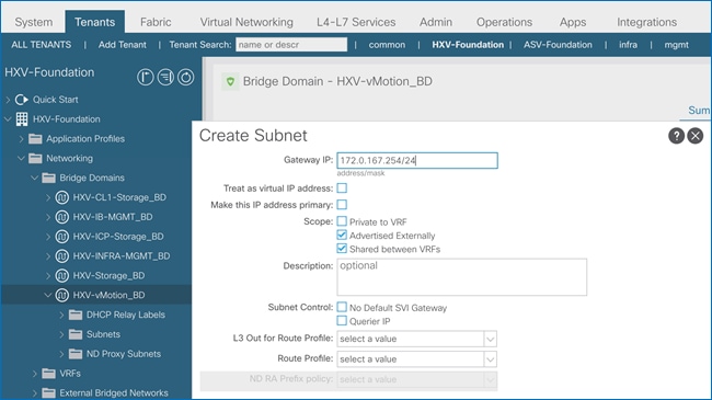
5. Click Submit.
Create Application Profile for HyperFlex vMotion Traffic
To create an application profile for HyperFlex vMotion traffic, follow these steps:
Setup Information
· Tenant: HXV-Foundation
· Application Profile: HXV-vMotion_AP
Deployment Steps
1. Use a browser to navigate to the APIC GUI. Log in using the admin account.
2. From the top navigation menu, select Tenants > HXV-Foundation. If you do not see this tenant in the top navigation menu, select Tenants > ALL TENANTS and double-click on HXV-Foundation.
3. From the left navigation pane, select Tenant HXV-Foundation. Right-click and select Create Application Profile.
4. In the Create Application Profile pop-up window, specify a Name the Application Profile.
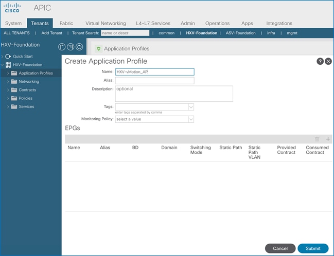
5. Click Submit to complete.
Create EPG for HyperFlex vMotion Traffic
To create an EPG for HyperFlex vMotion traffic, follow these steps:
Setup Information
· Tenant: HXV-Foundation
· Application Profile: HXV-vMotion_AP
· Bridge Domain: HXV-vMotion_BD
· EPG: HXV-vMotion_EPG
Deployment Steps
1. Use a browser to navigate to the APIC GUI. Log in using the admin account.
2. From the top navigation menu, select Tenants > HXV-Foundation. If you do not see this tenant in the top navigation menu, select Tenants > ALL TENANTS and double-click on HXV-Foundation.
3. From the left navigation pane, select and expand Tenant HXV-Foundation > Application Profiles > HXV-vMotion_AP. Right-click and select Create Application EPG.
4. In the Create Application EPG pop-up window, specify a Name for the EPG. For Bridge Domain, select the previously created Bridge Domain.

5. Click Finish.
Associate EPG with UCS Domain
To associate the HyperFlex vMotion EPG with UCS Domain, follow these steps:
Setup Information
· Tenant: HXV-Foundation
· Application Profile: HXV-vMotion_AP
· Bridge Domain: HXV-vMotion_BD
· EPG: HXV-vMotion_EPG
· Domain: HXV-UCS_Domain
Deployment Steps
1. Use a browser to navigate to the APIC GUI. Log in using the admin account.
2. From the top navigation menu, select Tenants > HXV-Foundation. If you do not see this tenant in the top navigation menu, select Tenants > ALL TENANTS and double-click on HXV-Foundation.
3. From the left navigation pane, select and expand Tenant HXV-Foundation > Application Profiles > HXV-vMotion_AP > Application EPGs > HXV-vMotion_EPG. Right-click and select Add L2 External Domain Association.
4. In the Add L2 External Domain Association pop-up window, select the previously created domain.
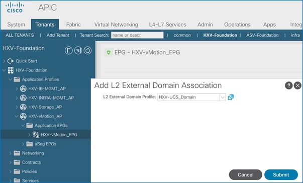
5. Click Submit.
Add Contract to Access Outside Networks and Services (Optional)
To enable access to network and services outside the ACI fabric through the Shared L3Out in the common Tenant, follow these steps:
Setup Information
· Tenant: HXV-Foundation
· Application Profile: HXV-vMotion_AP
· EPG: HXV-vMotion_EPG
· Contract: Allow-Shared-L3Out
Deployment Steps
1. Use a browser to navigate to the APIC GUI. Log in using the admin account.
2. From the top navigation menu, select Tenants > HXV-Foundation. If you do not see this tenant in the top navigation menu, select Tenants > ALL TENANTS and double-click on HXV-Foundation.
3. From the left navigation pane, select and expand Tenant HXV-Foundation > Application Profiles > HXV-vMotion_AP > Application EPGs > HXV-vMotion_EPG. Right-click HXV-vMotion_EPG and select Add Consumed Contract.
4. In the Add Consumed Contract pop-up window, select the Allow-Shared-L3Out contract from the drop-down list.
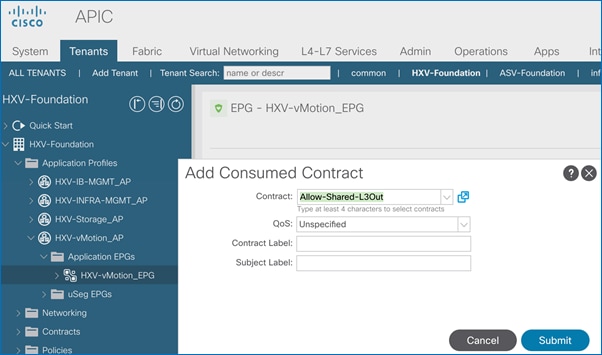
5. Click Submit.
This section provides the detailed procedures for deploying a 4-node standard HyperFlex cluster from the cloud using Cisco Intersight. The cluster can also be installed and deployed using an on-premise HyperFlex Installer virtual machine. This cluster will serve as an optional Management cluster in this design. In this design, this cluster will host virtual machines that provide management, infrastructure, and other services to other HyperFlex cluster and Cisco UCS systems that connect to the same ACI Multi-Pod fabric. It will also be used to hosting monitoring and other operational tools for managing the active-active data centers. VMware vCenter that manages the cluster and other infrastructure services such as Active Directory, DNS, and so on, are located outside the ACI fabric and reachable through the shared L3Out connection in each Pod.
Topology
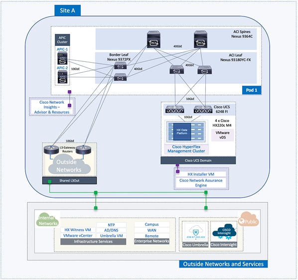
Setup ACI Fabric for HyperFlex Standard Cluster
To deploy a HyperFlex cluster in the ACI Fabric, the fabric must provide reachability to the following key infrastructure networks:
· In-Band management network for management connectivity to ESXi hosts and HyperFlex Storage Controller virtual machines (SCVM) in the HyperFlex cluster.
· Storage data network for storage connectivity to ESXi hosts and HyperFlex Storage Controller virtual machines in the HyperFlex cluster. Every HyperFlex cluster should use a dedicated storage data network.
· VMware vMotion network for virtual machine migration between ESXi hosts that connect to this network.
· Access to infrastructure, management, and other services. In this design, these services are deployed either in the Management HyperFlex cluster or outside the ACI fabric reachable through the shared L3Out.
In this design, all HyperFlex clusters share the same in-band management and vMotion networks but a dedicated storage data network is used for each HyperFlex cluster. Storage data for any HyperFlex should always be on a dedicated network.
The ACI constructs for in-band and vMotion networks were deployed in the previous section but there is additional configuration required which will be completed in this section. For the storage data network, only the Tenant and VRF configuration were done so all remaining configuration will be completed in this section. The configuration will enable traffic forwarding through the ACI fabric for HyperFlex endpoints connected to this network. These networks are critical for deploying and managing the HyperFlex cluster.
This section enables foundational infrastructure connectivity for the optional HyperFlex Management (standard) cluster in Pod-1.
Create Static Binding for In-Band Management to HyperFlex Standard Cluster
Follow the procedures outlined in this section to statically bind the in-band management EPG to the corresponding in-band management VLAN on the vPC interfaces going to HyperFlex UCS Domain.
Setup Information
· Tenant: HXV-Foundation
· Application Profile: HXV-IB-MGMT_AP
· EPG: HXV-IB-MGMT_EPG
· Static Paths: HXV-UCS_6200FI-A_IPG, HXV-UCS_6200FI-B_IPG
· VLAN: 118
Deployment Steps
1. Use a browser to navigate to the APIC GUI. Log in using the admin account.
2. From the top navigation menu, select Tenants > HXV-Foundation. If you do not see this tenant in the top navigation menu, select Tenants > ALL TENANTS and double-click on HXV-Foundation.
3. From the left navigation pane, select and expand Tenant HXV-Foundation > Application Profiles > HXV-IB-MGMT_AP > Application EPGs > HXV-IB-MGMT_EPG. Right-click and select Deploy Static EPG on PC, VPC or Interface.
4. In the Deploy Static EPG on PC, VPC or Interface pop-up window, for Path Type, select Virtual Port Channel. For the Path, select the vPC to the first Cisco UCS Fabric Interconnect from the drop-down list. For the Port Encap, specify the VLAN ID for the In-Band Management EPG. For the Deployment Immediacy, select Immediate.
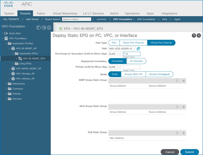
5. Click Submit.
6. Repeat steps 1-5 to bind the EPG to the VLAN on the second vPC going to the second Cisco UCS Fabric Interconnect in the same UCS domain. The resulting bindings are highlighted below.
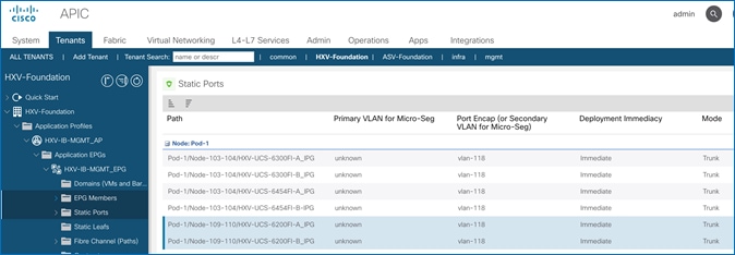
Create Static Binding for vMotion to HyperFlex Standard Cluster
Follow the procedures outlined in this section to statically bind the HyperFlex vMotion EPG and VLANs to vPC interfaces going to the UCS Domain.
Setup Information
· Tenant: HXV-Foundation
· Application Profile: HXV-vMotion_AP
· EPG: HXV-vMotion_EPG
· Static Paths: HXV-UCS_6200FI-A_IPG, HXV-UCS_6200FI-B_IPG
· VLAN: 3018
Deployment Steps
1. Use a browser to navigate to the APIC GUI. Log in using the admin account.
2. From the top navigation menu, select Tenants > HXV-Foundation. If you do not see this tenant in the top navigation menu, select Tenants > ALL TENANTS and double-click on HXV-Foundation.
3. From the left navigation pane, select and expand Tenant HXV-Foundation > Application Profiles > HXV-vMotion_AP > Application EPGs > HXV-vMotion_EPG. Right-click and select Deploy Static EPG on PC, VPC or Interface.
4. In the Deploy Static EPG on PC, VPC or Interface pop-up window, for Path Type, select Virtual Port Channel. For the Path, select the vPC to the first UCS Fabric Interconnect from the drop-down list. For the Port Encap, specify the VLAN ID for the vMotion EPG. For the Deployment Immediacy, select Immediate.
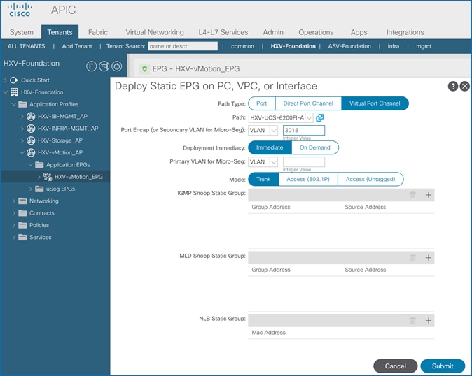
5. Click Submit.
6. Repeat steps 1-5 to bind the EPG to the second vPC going to the second UCS Fabric Interconnect in the same UCS domain.
Configure ACI Fabric for Storage Data Traffic on HyperFlex Standard Cluster
The configuration in this section will enable the forwarding of storage data traffic through the ACI fabric. The storage data network, in this case, will be used by nodes in the HyperFlex standard cluster. This network is also used by ESXi hosts to access the storage data services provided by the HyperFlex cluster.
For a HyperFlex standard cluster, this configuration is required so that ACI can forward traffic between Cisco UCS Fabric Interconnects in a UCS domain. A failure event can cause hosts to forward storage data traffic through different Cisco UCS Fabric Interconnects and traffic between Cisco UCS FIs will need to be forwarded by ACI.
Create Bridge Domain for HyperFlex Storage Data Traffic on HyperFlex Standard Cluster
To create a Bridge Domain for storage data traffic, follow these steps:
Setup Information
· Tenant: HXV-Foundation
· VRF: HXV-Foundation_VRF
· Bridge Domain: HXV-Storage_BD
Deployment Steps
1. Use a browser to navigate to the APIC GUI. Log in using the admin account.
2. From the top navigation menu, select Tenants > HXV-Foundation. If you do not see this tenant in the top navigation menu, select Tenants > ALL TENANTS and double-click HXV-Foundation.
3. From the left navigation pane, expand and select Tenant HXV-Foundation > Networking > Bridge Domains. Right-click and select Create Bridge Domain.
4. In the Create Bridge Domain wizard, for Name, specify a name for the bridge domain. For VRF, select the previously created VRF from the drop-down list. For Forwarding, select Custom from the drop-down list. For L2 Unknown Unicast, select Flood from the drop-down list. The checkbox for ARP Flooding should now show up and be enabled.
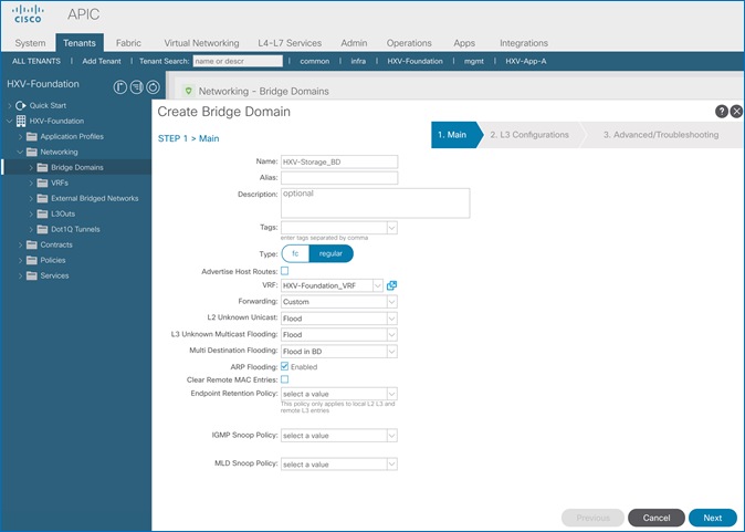
5. Click Next.
6. In the L3 Configurations section, disable Unicast Routing (optional). For EP Move Detection Mode, select the checkbox to enable GARP based detection. See Review/Enable ACI Fabric Settings section for more details.
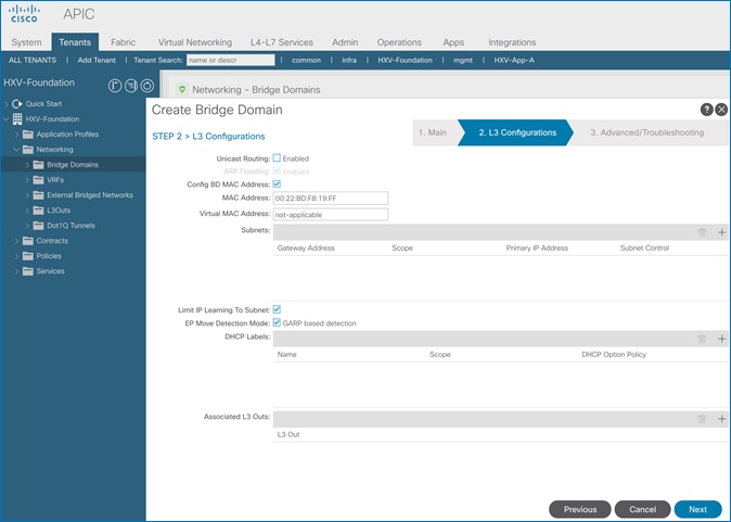
7. Click Next. Skip the Advanced/Troubleshooting section. Click Finish to complete.
Create Application Profile for HyperFlex Storage Data Traffic
To create an application profile for HyperFlex storage data traffic, follow these steps. The same Application profile will be used for storage data by all HyperFlex clusters that connect to the ACI Multi-Pod fabric.
Setup Information
· Tenant: HXV-Foundation
· Application Profile: HXV-Storage_AP
Deployment Steps
1. Use a browser to navigate to the APIC GUI. Log in using the admin account.
2. From the top navigation menu, select Tenants > HXV-Foundation. If you do not see this tenant in the top navigation menu, select Tenants > ALL TENANTS and double-click on HXV-Foundation.
3. From the left navigation pane, right-click Tenant HXV-Foundation and select Create Application Profile.
4. In the Create Application Profile pop-up window, specify a Name the Application Profile.
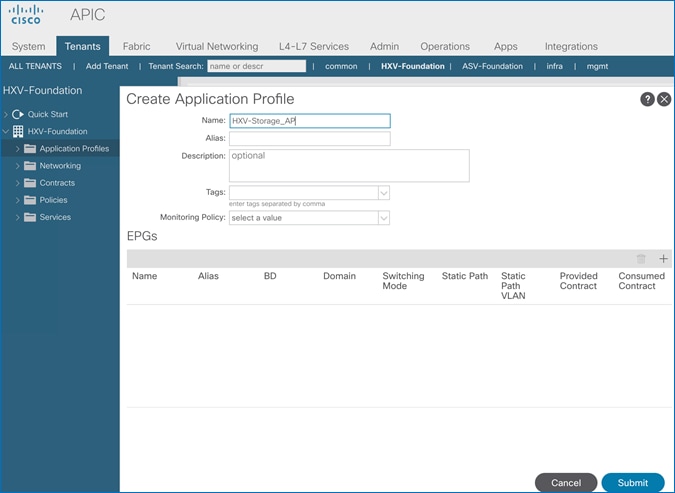
5. Click Submit to complete.
Create EPG for HyperFlex Storage on HyperFlex Standard Cluster
To create an EPG for HyperFlex storage data traffic, follow these steps:
Setup Information
· Tenant: HXV-Foundation
· Application Profile: HXV-Storage_AP
· Bridge Domain: HXV-Storage_BD
· EPG: HXV-CL0-StorData_EPG
Deployment Steps
1. Use a browser to navigate to the APIC GUI. Log in using the admin account.
2. From the top navigation menu, select Tenants > HXV-Foundation. If you do not see this tenant in the top navigation menu, select Tenants > ALL TENANTS and double-click on HXV-Foundation.
3. From the left navigation pane, select and expand Tenant HXV-Foundation > Application Profiles > HXV-Storage_AP. Right-click and select Create Application EPG.
4. In the Create Application EPG pop-up window, specify a Name for the EPG. For Bridge Domain, select the previously created Bridge Domain.
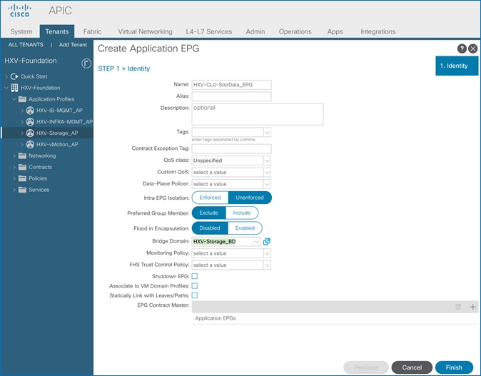
5. Click Finish.
Associate EPG for Storage Data Traffic with UCS Domain
To associate the HyperFlex Storage EPG with the UCS Domain, follow these steps:
Setup Information
· Tenant: HXV-Foundation
· Application Profile: HXV-Storage_AP
· Bridge Domain: HXV-Storage_BD
· EPG: HXV-CL0-StorData_EPG
· Domain: HXV-UCS_Domain
Deployment Steps
1. Use a browser to navigate to the APIC GUI. Log in using the admin account.
2. From the top navigation menu, select Tenants > HXV-Foundation. If you do not see this tenant in the top navigation menu, select Tenants > ALL TENANTS and double-click on HXV-Foundation.
3. From the left navigation pane, select and expand Tenant HXV-Foundation > Application Profiles > HXV-Storage_AP > Application EPGs > HXV-CL0-StorData_EPG. Right-click and select Add L2 External Domain Association.
4. In the Add L2 External Domain Association pop-up window, select the previously created domain.
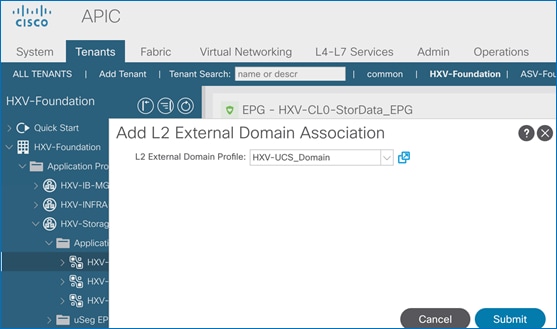
5. Click Submit.
Create Static Binding for Storage Data Traffic to HyperFlex Standard Cluster
To statically bind the HyperFlex Storage EPG and VLANs to vPC interfaces going to the UCS Domain that connect to the HyperFlex standard cluster, follow these steps:
Setup Information
· Tenant: HXV-Foundation
· Application Profile: HXV-Storage_AP
· EPG: HXV-CL0-StorData_EPG
· Static Paths: HXV-UCS_6200FI-A_IPG, HXV-UCS_6200FI-B_IPG
· VLAN: 3118
Deployment Steps
1. Use a browser to navigate to the APIC GUI. Log in using the admin account.
2. From the top navigation menu, select Tenants > HXV-Foundation. If you do not see this tenant in the top navigation menu, select Tenants > ALL TENANTS and double-click on HXV-Foundation.
3. From the left navigation pane, select and expand Tenant HXV-Foundation > Application Profiles > HXV-Storage_AP > Application EPGs > HXV-CL0-StorData_EPG. Right-click and select Deploy Static EPG on PC, VPC or Interface.
4. In the Deploy Static EPG on PC, VPC or Interface pop-up window, for Path Type, select Virtual Port Channel. For the Path, select the vPC to the first UCS Fabric Interconnect from the drop-down list. For the Port Encap, specify the VLAN ID for the storage data EPG. For the Deployment Immediacy, select Immediate.
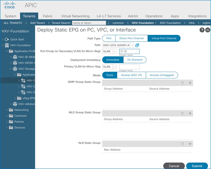
5. Click Submit.
6. Repeat steps 1-5 to bind the EPG to the second vPC going to the second Cisco UCS Fabric Interconnect in the same UCS domain. The resulting bindings are highlighted below.
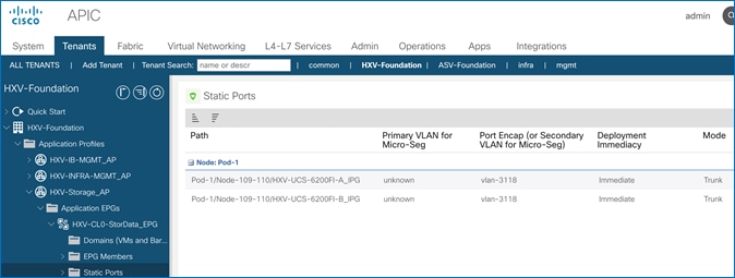
Install HyperFlex Cluster (Management) using Cisco Intersight
Cisco Intersight installation will configure Cisco UCS policies, templates, service profiles, and settings, as well as assigning IP addresses to the HX servers that come from the factory with ESXi hypervisor software preinstalled. The installer will deploy the HyperFlex controller virtual machines and software on the nodes, add the nodes to VMware vCenter managing the HX Cluster, and finally create the HyperFlex cluster and distributed filesystem. The above setup is done through a single workflow by providing the necessary information through an Installation wizard on Cisco Intersight.
![]() Screenshots in this section are from a previous release of this CVD. For this CVD, the testbed environment for the previous CVD release was upgraded and re-deployed. Any screenshots showing the initial install and setup of the cluster are therefore based on the previous CVD release.
Screenshots in this section are from a previous release of this CVD. For this CVD, the testbed environment for the previous CVD release was upgraded and re-deployed. Any screenshots showing the initial install and setup of the cluster are therefore based on the previous CVD release.
Prerequisites
The prerequisites for installing a HyperFlex system from Cisco Intersight are as follows:
1. Factory installed HX Controller VM with HX Data Platform version 2.5(1a) or later, must be present on the HX servers. Intersight deployment is not supported after cluster clean-up is completed. However, all NEW HX servers may be deployed as-is.
2. Device Connectors on Fabric Interconnects must be able to resolve svc.ucs-connect.com.
3. Allow outbound HTTPS connections (port 443) initiated from the Device Connectors on Fabric Interconnects. HTTP Proxy is supported.
4. Device Connectors (embedded in Fabric Interconnects) must be claimed and connected to Cisco Intersight – see Enable Cisco Intersight Cloud-based Management section.
5. Controller VM’s management interface must be able to resolve download.intersight.com.
6. Allow outbound HTTPS connections (port 443) initiated from Controller virtual machine’s management interface. HTTP Proxy is supported.
7. Reachability from Cisco Intersight to the out-of-band management interfaces on Fabric Interconnects that the HyperFlex system being deployed connects to.
8. Reachability from Cisco Intersight to the out-of-band management (CIMC) interfaces on the servers, reachable via the Fabric Interconnects’ management interfaces. This network (ext-mgmt) should be in the same subnet as the Fabric Interconnect management interfaces.
9. Reachability from Cisco Intersight to the ESXi in-band management interface of the hosts in the HyperFlex cluster being installed.
10. Reachability from Cisco Intersight to the VMware vCenter Server that will manage the HyperFlex cluster(s) being deployed. Note: The VMware vCenter Virtual Machine must be hosted on a separate virtualization environment and should not be on the HyperFlex cluster being deployed.
11. Reachability from Cisco Intersight to the DNS server(s) for use by the HyperFlex cluster being installed.
12. Reachability from Cisco Intersight to the NTP server(s) for use by the HyperFlex cluster being installed.
13. ACI Multi-Pod Fabric setup to enable connectivity to HyperFlex cluster networks - ESXi and Storage Controller management, ESXi and Storage Data networks, vMotion and Application VM networks.
14. Reachability from VMware vCenter to ESXi and Storage Controller Management networks.
15. Enable the necessary ports to install HyperFlex from Cisco Intersight. For more information, see Networking Ports section in Appendix A of the HyperFlex Hardening Guide: https://www.cisco.com/c/dam/en/us/support/docs/hyperconverged-infrastructure/hyperflex-hx-data-platform/HX-Hardening_Guide_v3_5_v12.pdf
16. Review the Pre-installation Checklist for Cisco HX Data Platform: https://www.cisco.com/c/en/us/td/docs/hyperconverged_systems/HyperFlex_HX_DataPlatformSoftware/HyperFlex_Preinstall_Checklist/b_HX_Data_Platform_Preinstall_Checklist.html
Setup Information
The setup information used in this design to install a standard HyperFlex cluster from Cisco Intersight is provided below.
Table 57 Cluster Configuration – General
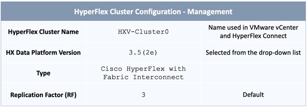
Table 58 Cluster Configuration - Security
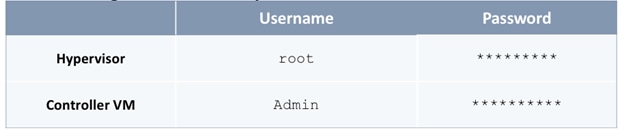
Table 59 Cluster Configuration – DNS, NTP and Timezone
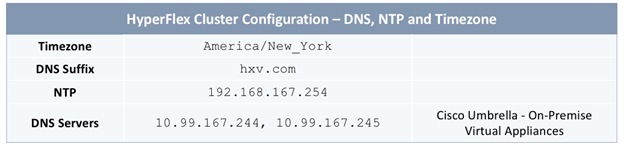
Table 60 Cluster Configuration – vCenter
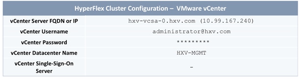
Table 61 Cluster Configuration – Storage Configuration
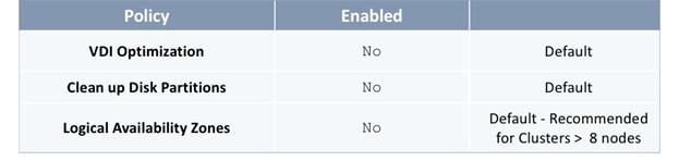
Table 62 Cluster Configuration – IP and Hostname
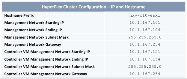
Table 63 Cluster Configuration – Cisco UCS Manager Configuration
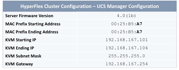
Table 64 Cluster Configuration – Network Configuration
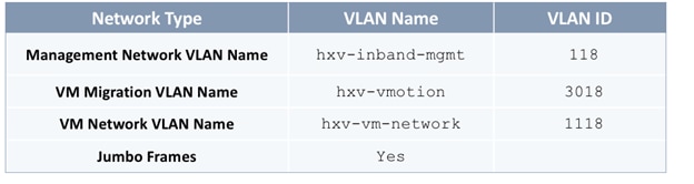
Table 65 Cluster Configuration – HyperFlex Storage Network
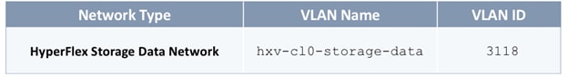
Deployment Steps
To install and deploy a HyperFlex standard cluster for Management from Cisco Intersight, complete the steps outlined in this section.
Verify Server Status before HyperFlex Install
Before starting the HyperFlex installation process that will create the service profiles and associate them with the servers, follow these steps to verify that the servers in the Cisco UCS domain have finished their discovery process and are in the correct state.
1. Use a browser to navigate to the UCS Manager GUI. Log in using the admin account.
2. From the left navigation pane, click the Equipment icon.
3. Navigate to All > Equipment. In the In the right windowpane, click-on the Servers tab.
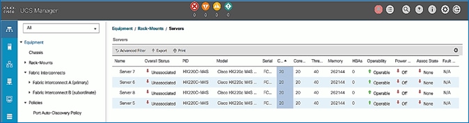
4. For the Overall Status, the servers should be in an Unassociated state. The servers should also be in an Operable state, powered Off and have no alerts with no faults or errors.
5. The servers are now ready for installing the HyperFlex Data Platform Software.
Connect to Cisco Intersight
To connect to Cisco Intersight, follow these steps:
1. Use a web browser to navigate to Cisco Intersight at https://intersight.com/.
2. Log in using a valid cisco.com account or single sign-on with your corporate authentication.
Deploy HyperFlex Cluster using Installation Wizard
To deploy the HyperFlex cluster using the wizard, follow these steps:
1. From Cisco Intersight, use the left navigation menu to select the Service Profiles icon.
2. In the right windowpane, click the Create HyperFlex Cluster Profile button on the top right to open the HyperFlex cluster creation wizard.
3. In the General section of the Create HyperFlex Cluster Profile wizard, specify a Name for the HyperFlex cluster. The same name will used for the HyperFlex Data Platform cluster and in VMware vCenter. For HyperFlex Data Platform Version, select the version from the drop-down list. For Type, select Cisco HyperFlex with Fabric Interconnect. For Replication Factor, select 3 (default) or 2.
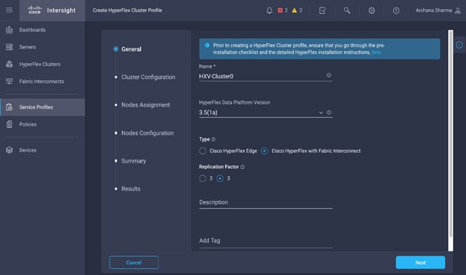
4. Click Next.
5. In the Cluster Configuration section of the Create HyperFlex Cluster Profile wizard, select and expand Security. Specify passwords for Hypervisor and Control VM Admin user (root).
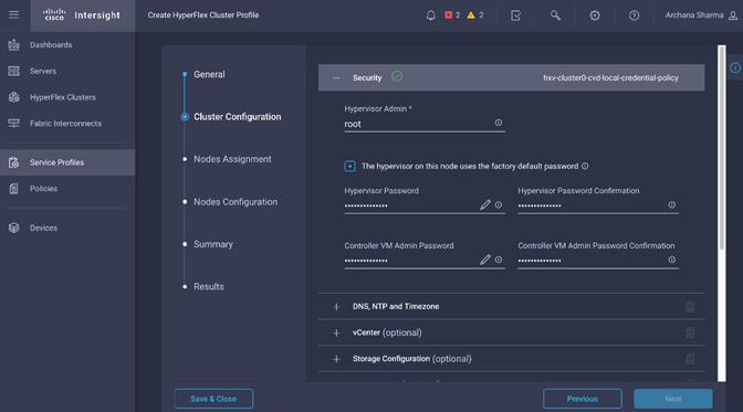
![]() Note the green check
Note the green check ![]() icon next to Security; this indicates that valid parameters were entered and that a policy was created (name on the top right). The policy is saved under Policies in the left navigation menu and can be individually accessed and edited.
icon next to Security; this indicates that valid parameters were entered and that a policy was created (name on the top right). The policy is saved under Policies in the left navigation menu and can be individually accessed and edited.
6. In the Cluster Configuration section of the Create HyperFlex Cluster Profile wizard, select and expand DNS, NTP and Timezone. For Timezone, select the appropriate Timezone from the drop-down list. For DNS Suffix, specify the Domain name for the cluster. For DNS Servers, specify the Domain Name Servers for the environment – use the [+] to add multiple servers. For NTP Servers, specify an NTP Server for the cluster – use the [+] to add multiple servers.
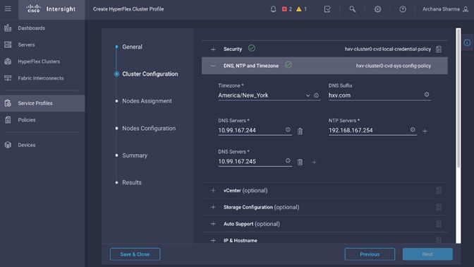
7. In the Cluster Configuration section of the Create HyperFlex Cluster Profile wizard, select and expand vCenter. Specify the information for the VMware vCenter managing the HX cluster in this section.
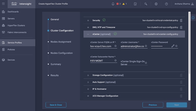
8. (Optional) In the Cluster Configuration section of the Create HyperFlex Cluster Profile wizard, select and expand Storage Configuration to specify storage policies such as VDI Optimization, Logical Availability Zones and so on.
9. (Optional) In the Cluster Configuration section of the Create HyperFlex Cluster Profile wizard, select and expand Auto Support to specify the email account to send support ticket notifications to.
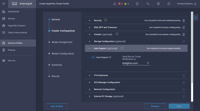
10. In the Cluster Configuration section of the Create HyperFlex Cluster Profile wizard, select and expand IP & Hostname. For the Hostname Prefix, specify a name for the ESXi hosts. For the Management Network, specify a starting and ending IP address, subnet mask and gateway for each ESXi host in the cluster. For the Controller VM Management Network, specify a starting and ending Management IP address, subnet mask and gateway for the controller virtual machine deployed on each host in the cluster.
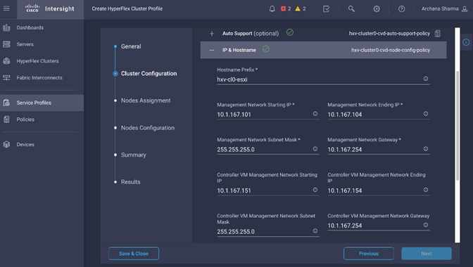
11. In the Cluster Configuration section of the Create HyperFlex Cluster Profile wizard, select and expand UCS Manager Configuration. For the Server Firmware Version, specify the Cisco UCS Manager version running on the Fabric Interconnects. For the MAC Prefix, specify a starting and ending MAC Prefix range for the HX nodes. For KVM management, specify a starting and ending IP address, subnet mask and gateway for out-of-band management of each HX node in the cluster.
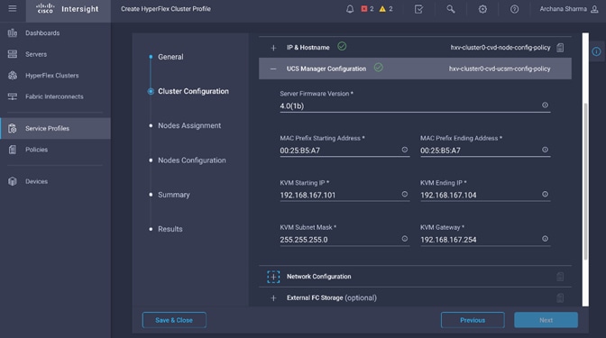
12. In the Cluster Configuration section of the Create HyperFlex Cluster Profile wizard, select and expand Network Configuration. For the Management Network VLAN, specify the VLAN Name and ID used for in-band ESXi management of HX nodes. For the VM Migration VLAN, specify the VLAN Name and VLAN ID used for vMotion. For the VM Network VLAN, specify the VLAN Name and VLAN ID used for virtual machines hosted on the HX cluster. For Jumbo Frames, enable it.
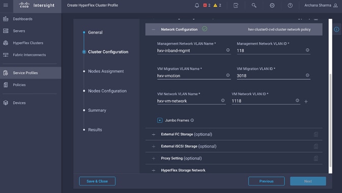
13. (Optional) In the Cluster Configuration section of the Create HyperFlex Cluster Profile wizard, select and expand External FC Storage if external FC storage is used.
14. (Optional) In the Cluster Configuration section of the Create HyperFlex Cluster Profile wizard, select and expand External iSCSI Storage if external FC storage is used.
15. (Optional) In the Cluster Configuration section of the Create HyperFlex Cluster Profile wizard, select and expand Proxy Setting if proxies are used.
16. In the Cluster Configuration section of the Create HyperFlex Cluster Profile wizard, select and expand HyperFlex Storage Network. For the Storage Network VLAN, specify the VLAN Name and ID used for the storage data network. This network will be accessed by ESXi hosts and Controller virtual machines.
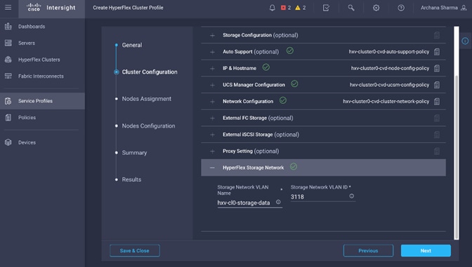
17. Review the Cluster Configuration section of the Create HyperFlex Cluster Profile wizard.
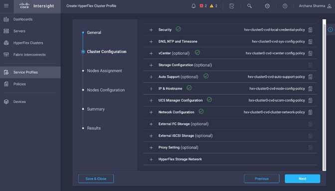
18. Click Next.
19. In the Nodes Assignment section of the Create HyperFlex Cluster Profile wizard, click Assign Nodes and select the nodes that should be added to the HX cluster.
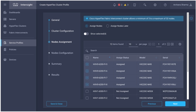
20. Click Next.
21. In the Nodes Configuration section of the Create HyperFlex Cluster Profile wizard, specify the Cluster Management Address.
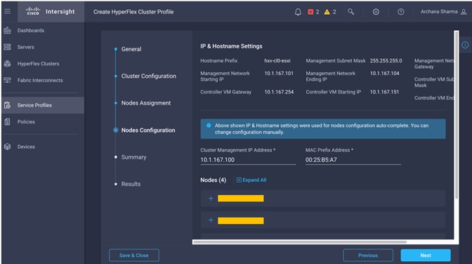
22. Click Next.
23. In the Summary section of the Create HyperFlex Cluster Profile wizard, review the configuration done so far. Click Validate to validate the configuration before deploying it.
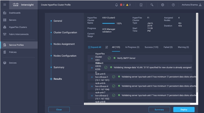
24. When the validation completes, click Deploy to install and configure the HX system.
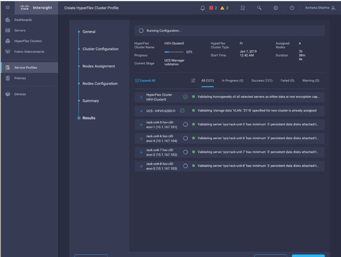
25. When in the install is complete, proceed to the next section to verify the cluster setup and proceed to the post-installation steps to complete the deployment.
Verify HyperFlex Cluster Installation
To verify that the install was successful from Cisco Intersight, follow these steps:
1. From Cisco Intersight, use the left navigation menu to select the HyperFlex Cluster icon.
2. In the right windowpane, review the information for the newly deployed HyperFlex cluster.
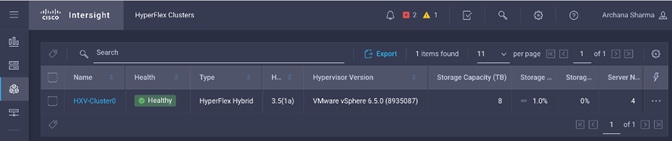
3. From the left navigation menu, select the Service Profiles icon.
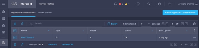
4. In the right windowpane, select the Service Profile for the newly deployed HX cluster and double-click the Service Profile to review the information in the General tab.
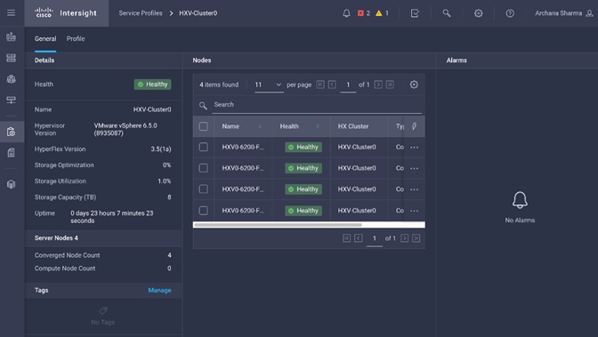
5. Select the Profile tab to review additional information about the newly deployed HX cluster.
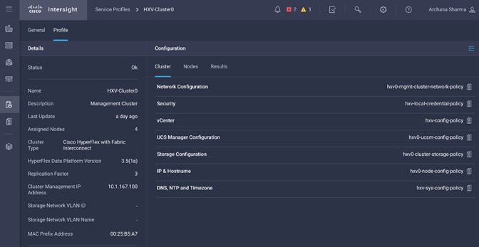
6. In the Configuration section on the right side of the window, under the Cluster tab, the individual policies are listed. Click the ![]() icon on the top right to see the details of each policy.
icon on the top right to see the details of each policy.
7. Navigate to the Nodes tab and Results tab for more details on the newly deployed HX cluster.
Complete Post-Installation Tasks
When the installation is complete, additional best-practices and configuration can be implemented using a Cisco provided post-installation script. The script should be run before deploying virtual machine workloads on the cluster. The script is executed from the HyperFlex Controller virtual machine and can do the following:
· License the hosts in VMware vCenter
· Enable HA/DRS on the cluster in VMware vCenter
· Suppress SSH/Shell warnings in VMware vCenter
· Configure vMotion in VMware vCenter
· Enables configuration of additional guest VLANs/port-groups
· Send test Auto Support (ASUP) email if enabled during the install process
· Perform HyperFlex Health check
To run the post-install script to do the above configuration, follow these steps:
1. SSH into a HX Controller VM. Log in using the admin/root account.
2. From the Controller VM, run the following command to execute the post-install script: /usr/share/springpath/storfs-misc/hx-scripts/post_install.py
3. Follow the on-screen prompts to complete the post-install configuration.
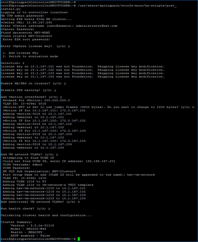
![]() Any VLANs created on the HyperFlex cluster and UCSM will need corresponding configuration in the ACI fabric to enable forwarding for that VLAN within the ACI Fabric.
Any VLANs created on the HyperFlex cluster and UCSM will need corresponding configuration in the ACI fabric to enable forwarding for that VLAN within the ACI Fabric.
Enable Smart Licensing
HyperFlex 2.5 and later utilizes Cisco Smart Licensing, which communicates with a Cisco Smart Account to validate and check out HyperFlex licenses to the nodes, from the pool of available licenses in the account. At the beginning, Smart Licensing is enabled but the HX storage cluster is unregistered and in a 90-day evaluation period or EVAL MODE. For the HX storage cluster to start reporting license consumption, it must be registered with the Cisco Smart Software Manager (SSM) through a valid Cisco Smart Account. Before beginning, verify that you have a Cisco Smart account, and valid HyperFlex licenses are available to be checked out by your HX cluster.
To create a Smart Account, see Cisco Software Central > Request a Smart Account: https://webapps.cisco.com/software/company/smartaccounts/home?route=module/accountcreation.
To activate and configure smart licensing, follow these steps:
1. SSH into a HX Controller VM. Log in using the admin/root account.
2. Confirm that your HX storage cluster is in Smart Licensing mode.
# stcli license show status
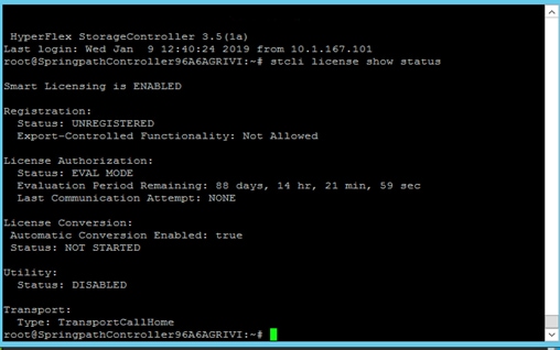
3. Feedback will show Smart Licensing is ENABLED, Status: UNREGISTERED, and the amount of time left during the 90-day evaluation period (in days, hours, minutes, and seconds).
4. Navigate to Cisco Software Central (https://software.cisco.com/) and log in to your Smart Account.
5. From Cisco Smart Software Manager, generate a registration token.
6. In the License pane, click Smart Software Licensing to open Cisco Smart Software Manager.
7. Click Inventory.
8. From the virtual account where you want to register your HX storage cluster, click General, and then click New Token.
9. In the Create Registration Token dialog box, add a short Description for the token, enter the number of days you want the token to be active and available to use on other products, and check Allow export controlled functionality on the products registered with this token.
10. Click Create Token.
11. From the New ID Token row, click the Actions drop-down list, and click Copy.
12. Log into the controller VM.
13. Register your HX storage cluster, where idtoken-string is the New ID Token from Cisco Smart Software Manager.
# stcli license register --idtoken idtoken-string 12.
14. Confirm that your HX storage cluster is registered.
# stcli license show summary
15. The cluster is now licensed and ready for production deployment.
Enable Syslog
To prevent the loss of diagnostic information when a host fails, ESXi logs should be sent to a central location. Logs can be sent to the VMware vCenter server or to a separate syslog server.
To configure syslog on ESXi hosts, follow these steps:
![]() You can also use a multi-exec tool such as MobaXterm or iTerm2 to simultaneously execute the same command on all servers in the cluster.
You can also use a multi-exec tool such as MobaXterm or iTerm2 to simultaneously execute the same command on all servers in the cluster.
1. Log into the ESXi host via SSH as the root user.
2. Enter the following commands, replacing the IP address in the first command with the IP address of the vCenter or the syslog server that will receive the syslog logs.
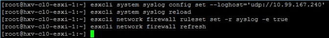
3. Repeat steps 1 and 2 for each HX ESXi host.
Manage Cluster using Cisco Intersight
Cisco Intersight provides a centralized dashboard with a single view of all Cisco UCS Domains, HyperFlex clusters and servers regardless of their location. The dashboard elements can be drilled down to get an overview of their health statuses, storage utilization, port counts, and more. For a standard HyperFlex cluster, Cisco Intersight can be used to do the initial install of a cluster as well. New features and capabilities are continually being added over time. Please see the Cisco Intersight website for the latest information.
Follow the steps outlined in the Enable Cisco Intersight Cloud-Based Management section to manage the HyperFlex Cluster from Cisco Intersight.
Manage Cluster using HyperFlex Connect
HyperFlex Connect is an easy to use, powerful primary management tool for managing HyperFlex clusters. HyperFlex Connect is a HTML5 web-based GUI tool that is accessible via the cluster management IP address. It runs on all HX nodes in the cluster for high availability. HyperFlex Connect can be accessed using either pre-defined Local accounts or Role-Based access (RBAC) by integrating authentication with VMware vCenter managing the HyperFlex cluster. With RBAC, you can use VMware credentials either local (for example, administrator@vsphere.local) or Single Sign-On (SSO) credential such as an Active Directory(AD) users defined on vCenter through AD integration.
To manage HyperFlex cluster using HyperFlex Connect, follow these steps:
1. Open a web browser and navigate to the IP address of the HX cluster (for example, https://10.1.167.100). Log in using the admin account. Log in using the admin account. Password should be same as the one specified for the Storage Controller VM during the installation process.
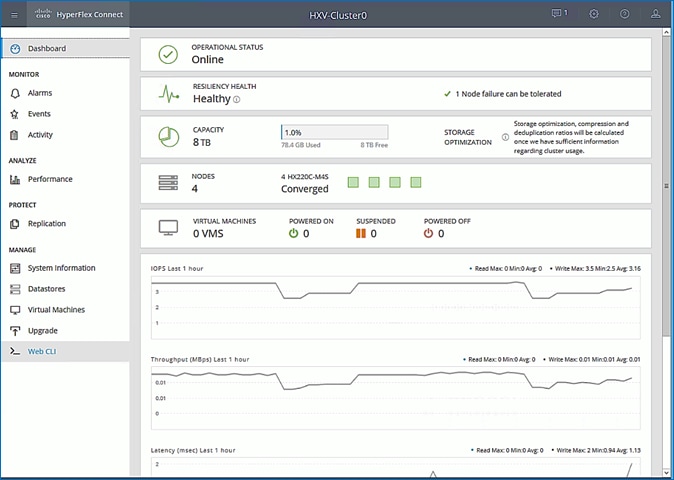
2. The Dashboard provides general information about the cluster’s operational status, health, Node failure tolerance, Storage Performance and Capacity Details and Cluster Size and individual Node health.
(Optional) Manage Cluster using VMware vCenter (via Plugin)
The Cisco HyperFlex vCenter Web Client Plugin can be deployed as a secondary tool to monitor and configure the HyperFlex cluster. The plugin is installed on the specified vCenter server by the HyperFlex installer. The plugin is accessible from vCenter Flash Web Client.
![]() This plugin is not supported in the HTML5 based VMware vSphere Client for vCenter.
This plugin is not supported in the HTML5 based VMware vSphere Client for vCenter.
To manage the HyperFlex cluster using the vCenter Web Client Plugin for vCenter 6.5, follow these steps:
1. Use a browser to navigate and VMware vCenter Web Client. Log in using an administrator account.
2. Navigate to the Home screen and click Global Inventory Lists.
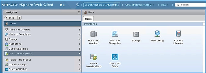
3. In the left navigation pane, click Cisco HX Data Platform.
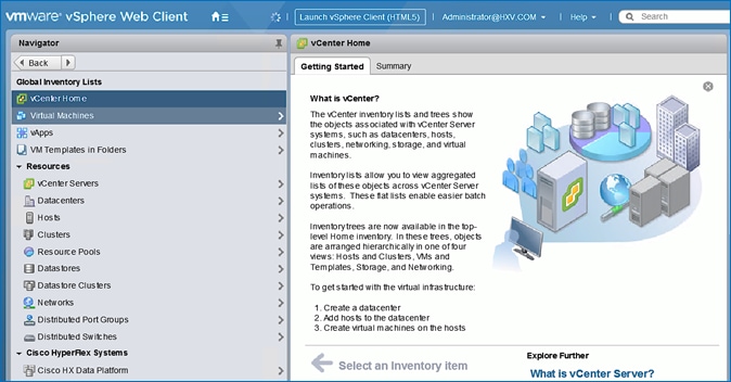
4. In the left navigation pane, click the newly deployed HX cluster (HXV-Cluster0) to manage.
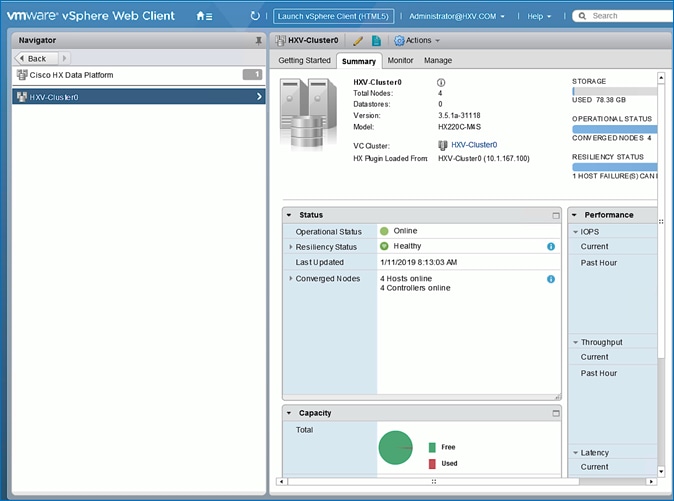
5. Use the Summary, Monitor or Manage tabs in the right-window pane to monitor and manage the cluster status, storage performance and capacity status, create datastores, upgrade cluster and more.
Enable/Disable Auto-Support and Notifications
Auto-Support is enabled if specified during the HyperFlex installation. Auto-Support enables Call Home to automatically send support information to Cisco TAC, and notifications of tickets to the email address specified. If the settings need to be modified, they can be changed in the HyperFlex Connect HTML management webpage.
To change Auto-Support settings, follow these steps:
1. Use a browser to navigate to HyperFlex Connect using the Management IP of the HX Cluster.
2. Log in using the admin account.
3. Click the gear shaped icon in the upper right-hand corner and click Auto-Support Settings.
4. Enable or Disable Auto-Support as needed. Enter the email address to receive notifications for Auto-Support events.
5. Enable or Disable Remote Support as needed. Remote support allows Cisco TAC to connect to the HX cluster and accelerate troubleshooting efforts.
6. If a web proxy is used, specify the settings for web proxy. Click OK.
7. To enable Email Notifications, click the gear shaped icon in top right corner, and click Notifications Settings. Enter the outgoing Mail Server Address information, the From Address and the Recipient List. Click OK.
Create Datastores for Virtual Machines
This task can be completed by using the vSphere Web Client HX plugin, or by using the HyperFlex Connect HTML management webpage.
To configure a new datastore from HyperFlex Connect, follow these steps:
1. Use a browser to navigate to HyperFlex Connect using the Management IP of the HX Cluster.
2. Enter Login credentials, either a local credential, or a vCenter RBAC credential with administrative rights. Click Login.
3. From the left navigation menu, select Manage > Datastores. Click the Create Datastore icon at the top.
4. In the Create Datastore pop-up window, specify a Name and Size for the datastore.
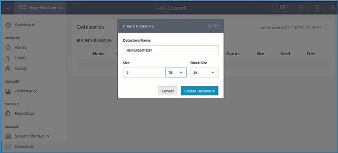
5. Click Create Datastore.
Migrate Virtual Networking to VMware vDS on HyperFlex Management Cluster
This section deploys the virtual networking for the virtual machines hosted on the Management cluster. APIC manages the virtual networking on this cluster through integration with VMware vCenter that manages the cluster. In this design, the Management cluster uses VMware vDS as the virtual switch for the VM networks. A Cisco AVE can also be used. The HyperFlex infrastructure networks (in-band management, storage data and vMotion networks) in the Management HyperFlex cluster will remain on the VMware vSwitch as deployed by the HyperFlex Installer. VMware vCenter that manages the Management HyperFlex cluster is located in a third location outside the ACI Multi-Pod fabric, and reachable through the Shared L3Out from each Pod.
Setup Information
The setup information for migrating the default virtual networking from VMware vSwitch to VMware vDS is provided below.
· VLAN Name: HXV0-VMM_VLANs
· VLAN Pool: 1018-1028
· Virtual Switch Name: HXV0-vDS
· Associated Attachable Entity Profile: HXV-UCS_AAEP
· VMware vCenter Credentials: <Username/Password> for the vCenter managing this cluster
· VMware vCenter Credentials – Profile Name: Administrator
· VMware vCenter Managing the VMM Domain: hxv-vcsa-0.hxv.com (10.99.167.240)
· DVS Version: vCenter Default
· VMware vCenter Datacenter: HXV-MGMT
· Default vSwitch for virtual machine networks: vswitch-hx-vm-network
· Uplinks on Default vSwitch for virtual machine Networks: vmnic2, vmnic6
Deployment Steps
To enable APIC-controlled virtual networking for the Management cluster, follow the procedures outlined in this section.
Create VLAN Pool for VMM Domain
To configure VLAN pools for use by VMs hosted on the Management cluster, follow these steps:
1. Use a browser to navigate to the APIC GUI. Log in using the admin account.
2. From the top navigation menu, select Fabric > Access Policies.
3. From the left navigation pane, expand and select Pools > VLAN. Right-click and select Create VLAN Pool.
4. In the Create VLAN Pool pop-up window, specify a Name for the pool to use for port-groups on VMware vDS. For Allocation Mode, select Dynamic Allocation. For Encap Blocks, click on the [+] icon on the right side to specify a VLAN range.
5. In the Create Ranges pop-up window, specify a VLAN range for the pool. Leave the other parameters as is.
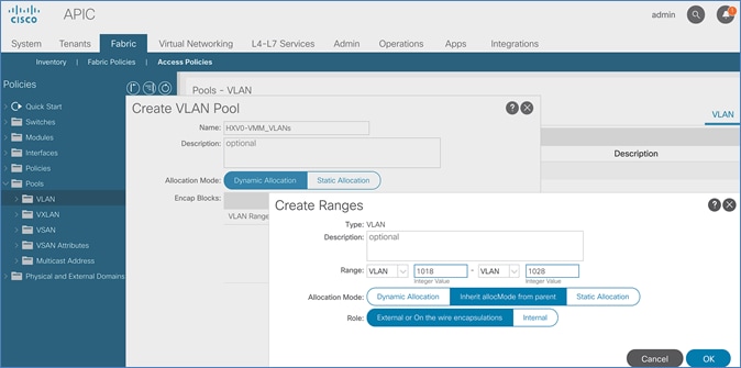
6. Click OK and then click Submit to complete.
Enable VMM Integration for HyperFlex Management Cluster
To enable VMM integration for the Management HyperFlex cluster, follow these steps:
1. Use a browser to navigate to the APIC GUI. Log in using the admin account.
2. From the top navigation menu, select Virtual Networking.
3. From the left navigation pane, select Quick Start.
4. From the right-window pane, select (VMware hypervisor) Create a vCenter Domain Profile.
5. In the Create vCenter Domain pop-up window, specify a Virtual Switch Name. For Virtual Switch, leave VMware vSphere Distributed Switch selected. For Associated Attachable Entity Profile, select the AAEP for the UCS domain that the VMM domain is hosted on. For VLAN Pool, select the previously created pool associated with this VMM domain from the drop-down list. Leave the other settings as is. For vCenter Credentials, click the [+] icon on the right.
6. In the Create vCenter Domain pop-up window, specify a Name (for example, Administrator) for the account and specify the vCenter credentials (Username, Password).
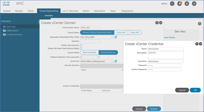
7. Click OK and in the Create vCenter Domain window, for vCenter, click the [+] icon on the right.
8. In the Add vCenter Controller pop-up window, enter a Name for the vCenter. For Host Name, specify the vCenter IP address or hostname. For DVS Version, leave it as vCenter Default. For Stats Collection, select Enabled. For Datacenter, enter the exact vCenter Datacenter name. For Associated Credential, select the vCenter credentials created in the last step (Administrator).
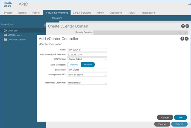
9. Click OK. In the Create vCenter Domain Window, select the MAC Pinning-Physical-NIC-load as the Port Channel Mode. Select CDP for vSwitch Policy.
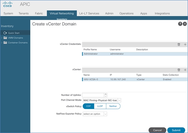
10. Click Submit to create the APIC managed vDS in VMware vCenter for the HyperFlex Management cluster
11. Use a browser to navigate to the VMware vCenter server managing the HyperFlex Management cluster. Select the vSphere Web Client of your choice. Log in using an Administrator account. Navigate to the data center for Management and select the Networking tab from the left navigation window. Select Networks > Distributed Switches in the right windowpane to verify that the vDS switch was created and setup correctly.
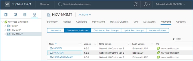
Add HyperFlex ESXi Hosts to VMware vSphere vDS
![]() The screenshots in this section are from the previous release of this CVD using VMware vSphere and VMware vCenter 6.5. However, the procedures for migrating VM networking to vDS from vSwitch are the same in the vSphere 6.7 environment used for this release. The vSphere environment was upgraded from 6.5 to 6.7 for this release of the CVD.
The screenshots in this section are from the previous release of this CVD using VMware vSphere and VMware vCenter 6.5. However, the procedures for migrating VM networking to vDS from vSwitch are the same in the vSphere 6.7 environment used for this release. The vSphere environment was upgraded from 6.5 to 6.7 for this release of the CVD.
To add the HyperFlex ESXi Hosts to the newly created vDS, follow these steps:
1. Use a browser to log into the VMware vCenter server managing the HyperFlex Management cluster. Select the vSphere Web Client of your choice. Log in using an Administrator account.
2. Navigate to the Home screen, select Networking in the Inventories section.
3. In the left navigation pane, expand the Datacenter with the newly deployed vDS. Open the vDS folder and select the vDS deployed by the APIC. Right-click and select Add and manage hosts.
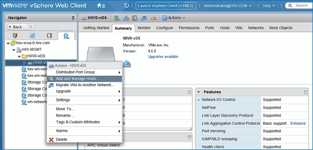
4. In the Add and Manage Hosts pop-up window, select the Add hosts option. Click Next.
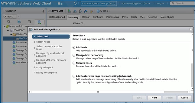
5. In the Select Hosts window, click [+ New host…] icon at the top to add new host.
6. In the Select new hosts pop-up window, select all hosts in the HX cluster.
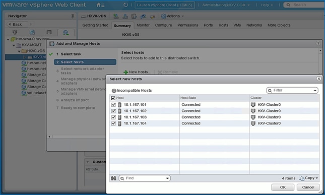
7. Click OK.
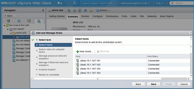
8. Click Next. Leave Manage physical adapters selected and de-select the other options.
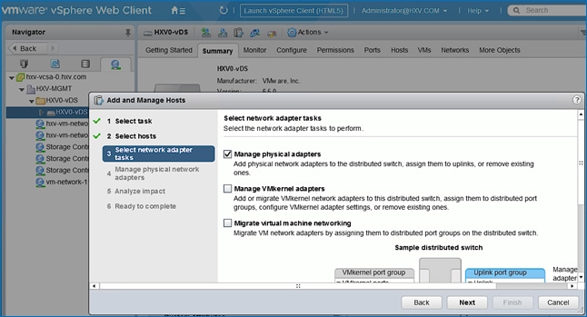
9. Click Next.
10. In the Manage physical network adapters window, for the first host, from the Host/Physical Network Adapters column, select the first vmnic (for example, vmnic2) that currently belongs to the HX VM Network vSwitch (for example, vswitch-hx-vm-network). Click the Assign uplink icon from the menu.
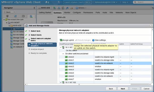
11. In the Select an Uplink for vmnic pop-up window, leave uplink 1 selected.
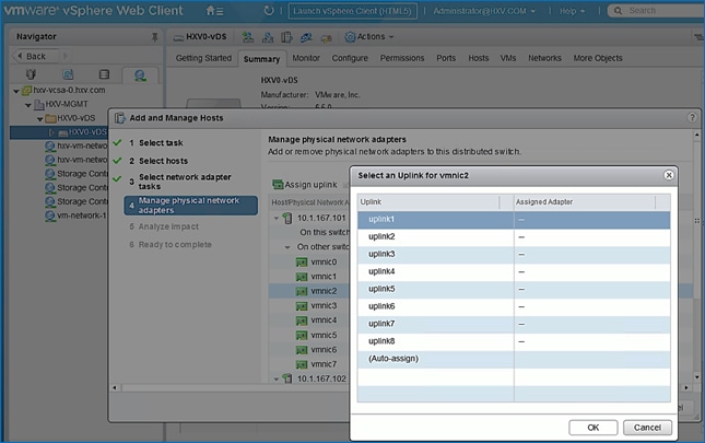
12. Click OK.
13. Repeat steps 1-14 for the second vmnic (for example, vmnic6) that currently belongs to the HX VM Network vSwitch (for example, vswitch-hx-vm-network) – assign it to uplink2.
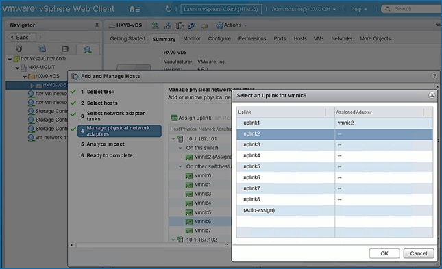
14. Click OK.
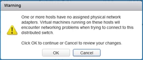
15. Click OK to accept the Warning.
16. Repeat steps 1-17 to move uplinks from vSwitch to vDS for all hosts in the cluster. If a server shows no physical adapter available for migration to vDS, exit the wizard. Select the host from left navigation pane and navigate to Configure > virtual Switches (under Networking) and select the vSwitch for vm-network (for example, vswitch-hx-vm-network) and remove the physical adapters. Once released from the vswitch, the physical adapters for that host can be added to the vDS from the wizard.
17. Click Next.
18. In the Analyze impact window, click Next.
19. Review the settings and click Finish to apply.
The management HyperFlex cluster is now ready for deploying virtual machines and as EPGs are deployed in the ACI fabric, the virtual networking will also be setup.
Deploy Virtual Machines – Infrastructure Management
In this design, the Management HyperFlex cluster hosts the infrastructure management virtual machines to manage other virtual server infrastructure on the same ACI Multi-Pod fabric. The HyperFlex Installer virtual machine for installing other HyperFlex clusters in the ACI Fabric is one of the infrastructure services hosted on the Management cluster. The HyperFlex Installer VM will deploy the HyperFlex stretched cluster in this solution.
The high-level steps for deploying the virtual machines on a HyperFlex cluster connected to a Cisco ACI Multi-Pod fabric are as follows:
· Add VLAN(s) to ACI Fabric for Infrastructure Management Virtual Machines – this is done by adding the VLANs to the VLAN Pool associated with the access layer connection to the Infrastructure Management virtual machines. Ideally, a pool of VLANs should be pre-defined for use by different types of infrastructure and management services rather than adding VLANs one at a time. In this design, VMM integration is enabled between the APIC and the vCenter managing the cluster to dynamically allocate and configure the virtual networking for infrastructure and management virtual machines. The VLAN Pool for use by VMM domain was completed in the Migrate Virtual Networking on HyperFlex Management Cluster to VMware vDS section. Additional VLANs can be added to the VMM VLAN Pool as needed.
· Define ACI Constructs for Infrastructure Management – this includes specifying the Tenant, VRF, Bridge Domain, Application Profile, EPGs, and Contracts so infrastructure virtual machines can be added to the ACI fabric. VMware vCenter and HX Installer virtual machines will be part of the existing Foundation Tenant and VRF but a new Application Profile, Bridge Domain and EPG will be created for the HyperFlex Installer and VMware vCenter virtual machines – they can also be deployed in separate EPGs as well. To host additional services such as AD/DNS, Umbrella Virtual Appliances, Monitoring tools etc. new EPGs and Tenants can also be provisioned as needed in the Management cluster.
· Enable contracts to allow communication between Infrastructure EPGs and other components in the network. For example, the Installer virtual machine will need out-of-band management access to Fabric Interconnects and in-band ESXi management access to the HX nodes.
· Deploy the infrastructure virtual machines in the HyperFlex Management cluster.
Configure ACI Fabric for Infrastructure Management
This section explains the ACI fabric setup for deploying infrastructure management virtual machines in the Management HyperFlex cluster. The same procedure can be used to bring up other virtual machines on the same cluster.
In this setup, the existing Foundation Tenant and VRF used for HyperFlex infrastructure will also be used to host the infrastructure and management virtual machines hosted on the Management cluster. For new Tenants, follow the steps for the Foundation Tenant and VRF before doing the configuration in this section.
Create Bridge Domain for Infrastructure Management
To create a Bridge Domain for Infrastructure Management virtual machines in the HyperFlex Management cluster, follow these steps using the setup information provided below:
· Tenant: HXV-Foundation
· VRF: HXV-Foundation_VRF
· Bridge Domain: HXV-INFRA-MGMT_BD
1. Use a browser to navigate to the APIC GUI. Log in using the admin account.
2. From the top navigation menu, select Tenants > HXV-Foundation.
3. From the left navigation pane, expand and select Tenant HXV-Foundation > Networking > Bridge Domains.
4. Right-click Bridge Domains and select Create Bridge Domain.
5. In the Create Bridge Domain wizard, for Name, specify a name (HXV-INFRA-MGMT_BD) for the bridge domain. For VRF, select the previously created VRF (HXV-Foundation_VRF) from the drop-down list. For Forwarding, select Custom from the drop-down list. For L2 Unknown Unicast, select Flood from the drop-down list. The checkbox for ARP Flooding should now show up as enabled.
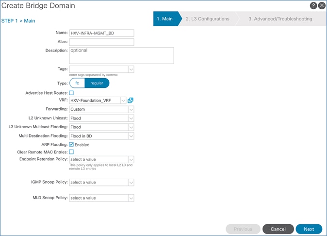
6. Click Next.
7. In the L3 Configurations section, for EP Move Detection Mode, select the checkbox to enable GARP based detection if needed. See Review/Enable ACI Fabric Settings section for details on when to enable this feature.
8. Click Next. Skip the Advanced/Troubleshooting section. Click Finish to complete.
Configure Subnet Gateway for Infrastructure Management
To configure a gateway for Infrastructure Management virtual machines, follow these steps using the setup information provided below:
· Tenant: HXV-Foundation
· Bridge Domain: HXV-INFRA-MGMT_BD
· BD Subnet: 10.10.167.254/24
1. Use a browser to navigate to the APIC GUI. Log in using the admin account.
2. From the top navigation menu, select Tenants > HXV-Foundation.
3. From the left navigation pane, select and expand Tenant HXV-Foundation > Networking > Bridge Domains > HXV-INFRA-MGMT_BD. Right-click and select Create Subnet.
4. In the Create Subnet pop-up window, for the Gateway IP, specify the IP address and mask for the gateway. For Scope, select Advertised Externally and Shared between VRFs. Leave everything else as is.
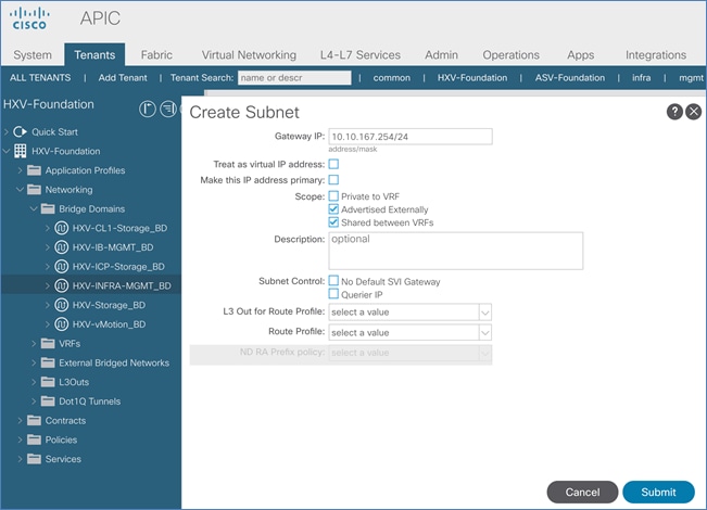
5. Click Submit.
Create Application Profile for In-Band Management
To create an application profile for Infrastructure Management virtual machines in the HyperFlex Management cluster, follow these steps using the setup information provided below:
· Tenant: HXV-Foundation
· Application Profile: HXV-INFRA-MGMT_AP
1. Use a browser to navigate to the APIC GUI. Log in using the admin account.
2. From the top navigation menu, select Tenants > HXV-Foundation.
3. From the left navigation pane, select Tenant HXV-Foundation. Right-click and select Create Application Profile.
4. In the Create Application Profile pop-up window, specify a Name for the Application Profile.
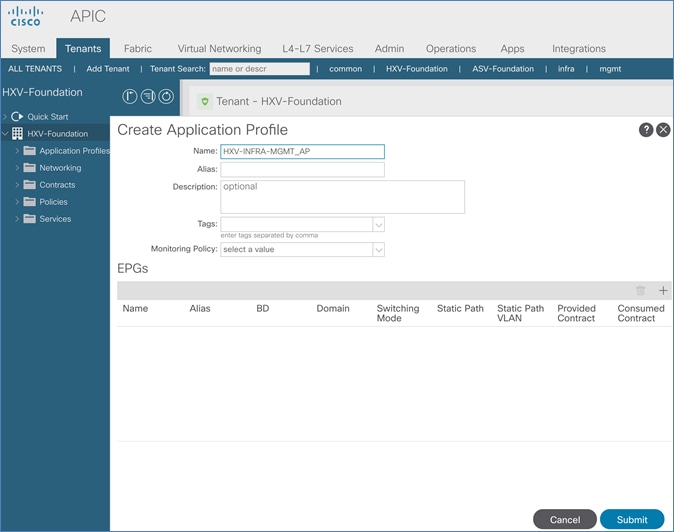
5. Click Submit to complete
Create EPG for Infrastructure Management and Associate with Bridge Domain
To create an EPG for Infrastructure Management virtual machines in the HyperFlex Management cluster, follow these steps using the setup information provided below:
· Tenant: HXV-Foundation
· Application Profile: HXV-INFRA-MGMT_AP
· Bridge Domain: HXV-INFRA-MGMT_BD
· EPG: HXV-INFRA-MGMT_EPG
1. Use a browser to navigate to the APIC GUI. Log in using the admin account.
2. From the top navigation menu, select Tenants > HXV-Foundation.
3. From the left navigation pane, select and expand Tenant HXV-Foundation > Application Profiles > HXV-INFRA-MGMT_AP. Right-click and select Create Application EPG.
4. In the Create Application EPG pop-up window, specify a Name(HXV-INFRA-MGMT_EPG) for the EPG. For Bridge Domain, select the previously created Bridge Domain (HXV-INFRA-MGMT_BD).
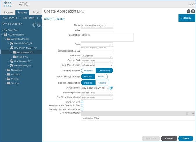
5. Click Finish.
Associate EPG with VMM Domain – Dynamic Binding
To associate the Infrastructure Management EPG with the VMM Domain, follow these steps:
· Tenant: HXV-Foundation
· Application Profile: HXV-INFRA-MGMT_AP
· EPG: HXV-INFRA-MGMT_EPG
· Domain: HXV0-vDS
1. Use a browser to navigate to the APIC GUI. Log in using the admin account.
2. From the top navigation menu, select Tenants > HXV-Foundation.
3. From the left navigation pane, select and expand Tenant HXV-Foundation > Application Profiles > HXV-INFRA-MGMT_AP > Application EPGs > HXV-INFRA-MGMT_EPG. Right-click and select Add VMM Domain Association.
4. In the Add VMM Domain Association pop-up window, for VMM Domain Profile, select the previously created VMM Domain from the list. For Deploy Immediacy and for Resolution Immediacy, select Immediate.
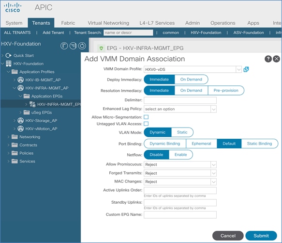
5. Click Submit.
Enable Contract to Access Outside Networks via Shared L3Out
To access networks outside the ACI fabric using the L3Out connection in each Pod, follow these steps:
· Tenant: HXV-Foundation
· Application Profile: HXV-INFRA-MGMT_AP
· EPG: HXV-INFRA-MGMT_EPG
· Consumed Contract: Allow-Shared-L3Out
1. Use a browser to navigate to the APIC GUI. Log in using the admin account.
2. From the top navigation menu, select Tenants > HXV-Foundation.
3. From the left navigation pane, select and expand Tenant HXV-Foundation > Application Profiles > HXV-INFRA-MGMT_AP > Application EPGs > HXV-INFRA-MGMT_EPG. Right-click and select Add Consumed Contract.
4. In the Add Consumed Contract pop-up window, select the L3Out contract from the drop-down list.
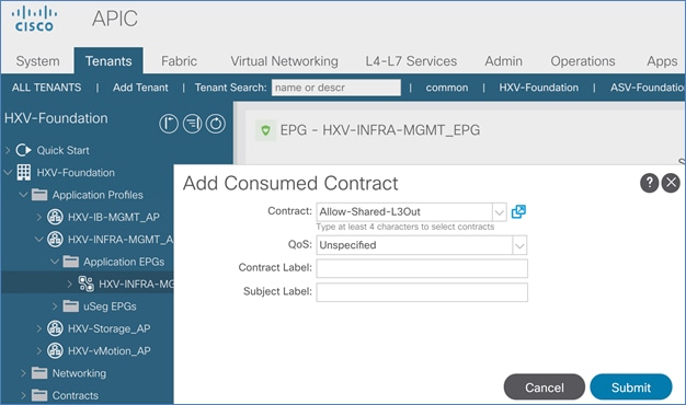
5. Click Submit.
Create Contract to Enable Access to Infrastructure Management
To access the infrastructure and management services hosted in the Management Cluster, follow these steps using the setup information provided below:
· Tenant: HXV-Foundation
· Application Profile: HXV-INFRA-MGMT_AP
· EPG: HXV-INFRA-MGMT_EPG
· Provided Contract: Allow-Infra-Mgmt
1. Use a browser to navigate to the APIC GUI. Log in using the admin account.
2. From the top navigation menu, select Tenants > HXV-Foundation.
3. From the left navigation pane, select and expand Tenant HXV-Foundation > Application Profiles > HXV-INFRA-MGMT_AP > Application EPGs > HXV-INFRA-MGMT_EPG. Right-click and select Add Provided Contract.
4. In the Add Provided Contract pop-up window, select Create Contract from the end of the drop-down list.
5. In the Create Contract pop-up window, specify a Name( Allow-Infra-Mgmt) for the Contract.
6. For Scope, select Tenant from the drop-down list.
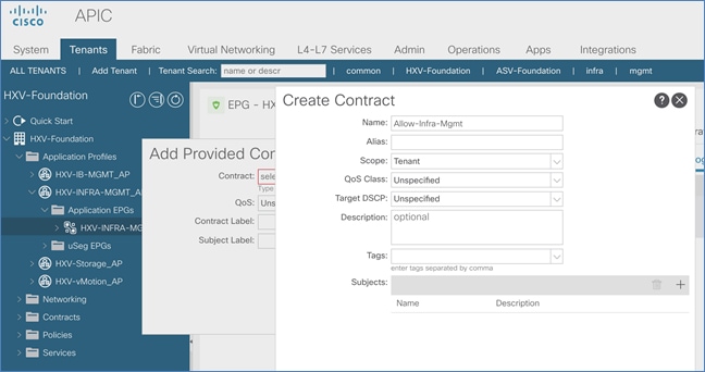
7. For Subjects, click [+] on the right to add a Contract Subject.
8. In the Create Contract Subject pop-up window, specify a Name (Allow-Infra-Mgmt_Subject) for the subject.
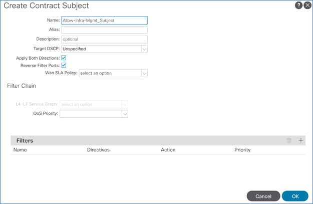
9. Under Filters, click [+] on the right to add a Contract Filter.
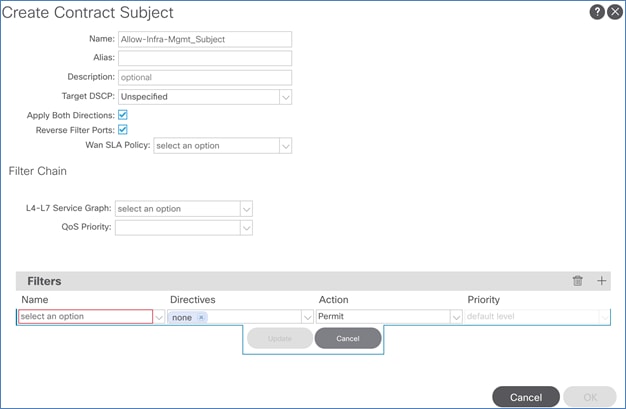
10. For Name, click the down-arrow to see the drop-down list. Click [+] to create a Filter.
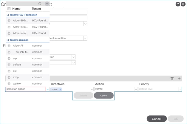
11. In the Create Filter pop-up window, specify a Name (Allow-Infra-Mgmt_Filter) for the filter. For Entries, click [+] to add an Entry. Enter a Name (Allow-All) for the Entry. For the EtherType, select IP from the drop-down list.
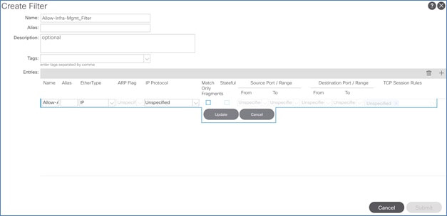
12. Click Update.
13. Click Submit.
14. In the Create Contract Subject pop-up window, click Update.
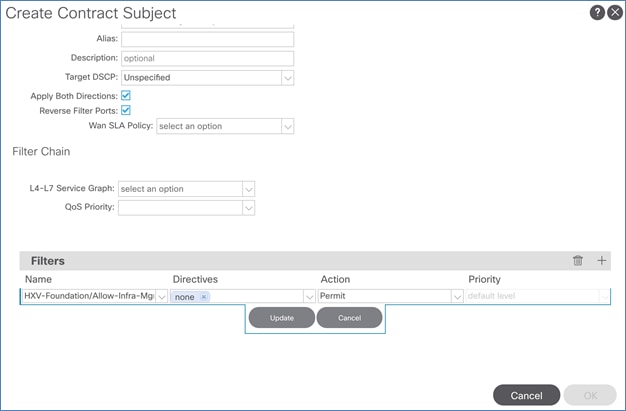
15. Click OK to finish creating the Contract Subject and close the window.
16. In the Create Contract pop-up window, click Submit to complete creating the Contract.
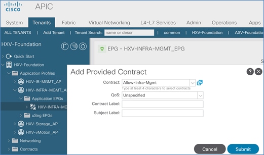
17. Click Submit to complete adding the Provided Contract. The contract can now be consumed by other EPGs that need reachability to the virtual machines in this EPG.
Enable Access to Infrastructure Management from Foundation Tenant EPGs
To enable connectivity between HyperFlex Installer VM (or other VMs in the HXV-INFRA-MGMT_EPG) and the endpoints in the HyperFlex infrastructure networks, follow these steps:
· Tenant: HXV-Foundation
· Application Profile: HXV-IB-MGMT_AP, HXV-Storage_AP, HXV-vMotion_AP
· EPG: HXV-IB-MGMT_EPG, HXV-CL0-StorData_EPG, HXV-CL0-StorData_EPG, HXV-vMotion_EPG
· Consumed Contract: Allow-Infra-Mgmt
1. Use a browser to navigate to the APIC GUI. Log in using the admin account.
2. From the top navigation menu, select Tenants > HXV-Foundation.
3. From the left navigation pane, select and expand Tenant HXV-Foundation > Application Profiles > HXV-IB-MGMT_AP > Application EPGs > HXV-IB-MGMT_EPG. Right-click and select Add Consumed Contract.
4. In the Add Consumed Contract pop-up window, select the contract from the drop-down list.
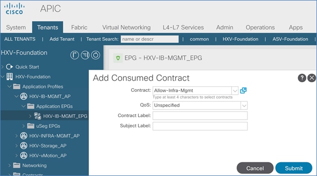
5. Click Submit. Endpoints in the in-band management EPG/network will now be able to access the virtual machines in the infrastructure management EPG/network.
6. Repeat steps 1-5 for the other HyperFlex infrastructure networks or EPGs that need access to management infrastructure virtual machines.
Deploy HX Installer Virtual Machine in the HyperFlex Management Cluster
This section explains the deployment of HyperFlex Installer virtual machine on the Management HyperFlex cluster.
The Management HyperFlex Cluster is managed by a VMware vCenter hosted outside the ACI Multi-Pod Fabric, reachable through the Shared L3Out setup between the ACI fabric and the existing (non-ACI) network. The HyperFlex Installer, once deployed, can be used to deploy any number of HyperFlex clusters. In this design, the HyperFlex Installer will be used in this design to deploy the HyperFlex stretched cluster for hosting Applications. See the Install HyperFlex Stretched Cluster section for more details.
Table 66 Setup Information
| VMware vCenter IP Address |
10.99.167.240 |
| Installer Virtual Machine |
|
| IP Address |
10.10.167.248/24 |
| Gateway |
10.10.167.254 (in the ACI Multi-Pod Fabric) |
| Network |
VLAN is dynamically allocated by APIC-managed VMware vDS Port-Group: HXV-Foundation|HXV-INFRA-MGMT_AP|HXV-INFRA-MGMT_EPG |
| DNS |
10.99.167.244, 10.99.167.245 |
| NTP |
192.168.167.254 |
To deploy the HyperFlex installer in the Management HyperFlex Cluster, follow these steps:
1. Use a browser to navigate to the VMware vCenter Server managing the Management cluster. Click the vSphere web client of your choice and log in using an Administrator account.
2. From the vSphere Web Client, navigate to Home > Hosts and Clusters.
3. From the left navigation pane, select the Datacenter > Cluster. Right-click to select Deploy OVF Template….
4. In the Deploy OVF Template wizard, for Select Template, select Local file and click the Browse button to locate and open the Cisco-HX-Data-Platform-Installer OVA file.
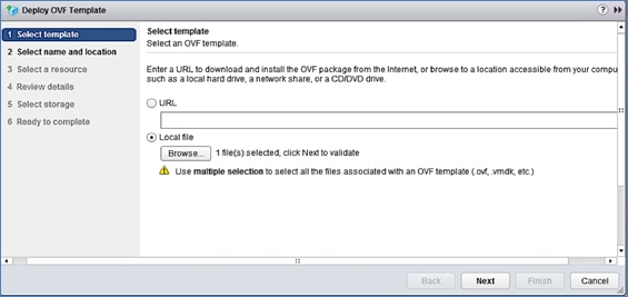
5. Click Next.
6. For Select name and location, specify a name for the virtual machine and select a folder location. Click Next.
7. For Select a resource, select a host or cluster or resource pool to locate the virtual machine. Click Next.
8. Review the details. Click Next.
9. For Select storage, select a datastore and Thin provision virtual disk format for the VM. Click Next.
10. For Select networks, use the drop-down list in the Destination Networks column to specify the network (HXV-Foundation|HXV-INFRA-MGMT_AP|HXV-INFRA-MGMT_EPG) the installer VM will communicate on. Click Next.
11. For Customize template, provide the IP Address, Mask, Gateway, DNS and NTP server info. Click Next.
12. Review the settings. Click Finish. Power on the virtual machine.
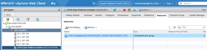
13. From VMware vCenter, console into the installer VM to verify setup. If the HyperFlex installer was deployed using DHCP, the leased IP address can be verified from the console. Login using the default username (root) and password (Cisco123).
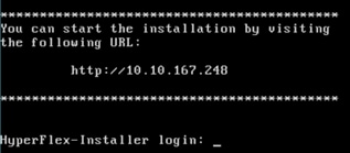
14. Verify the IP address, NTP status, DNS configuration and change the default password as shown below.
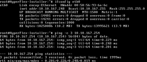
The Installer virtual machine is now ready for installing HyperFlex clusters.
This section provides the detailed procedures for deploying an 8-node HyperFlex stretched cluster using an on-premise HyperFlex Installer virtual machine. This cluster will serve as an Application cluster in this design for hosting application virtual machines. The Installer VM to install the cluster will be hosted on the Management Cluster. Other infrastructure services such as Active Directory, DNS, VMware vCenter and HyperFlex Witness are located outside the ACI fabric and accessed through the shared L3Out connection from each Pod.
![]() Cisco Intersight currently does not support the install of HyperFlex stretched clusters.
Cisco Intersight currently does not support the install of HyperFlex stretched clusters.
Topology
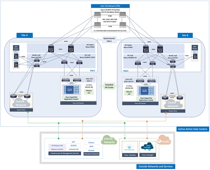
Deployment Overview
The high-level steps for deploying an Application HyperFlex cluster in a Cisco ACI Multi-Pod fabric are as follows:
· Setup Cisco UCS domains for HyperFlex stretched cluster - one in each Pod.
· Setup ACI fabric to enable HyperFlex infrastructure connectivity necessary for installing and operating the Cisco HyperFlex stretch cluster. This requires ACI constructs (Tenant, VRF, Bridge Domain and Application Profile) to be defined in the fabric. This connectivity must be in place before the stretch cluster can be installed across the ACI Multi-Pod fabric.
· Install HyperFlex stretched cluster using the HyperFlex Installer VM hosted on the Management cluster.
· Create contracts to enable communication between different tiers of the applications. Contracts are also necessary to allow users to access the Application, and to access outside networks and services using the shared L3Out in each Pod.
· Deploy application virtual machines on the Application HyperFlex cluster.
· Add virtual machines to the port-group corresponding to the EPG in VMware vCenter.
Setup Cisco UCS Domain for HyperFlex Stretched Cluster
Follow the procedures outlined in the Setup Cisco UCS Domains section to deploy and setup the two Cisco UCS domains that the HyperFlex stretched cluster nodes in Pod-1 and Pod-2 will connect to.
Setup ACI Fabric for HyperFlex Stretched Cluster
To deploy a HyperFlex cluster in the ACI Fabric, the fabric must provide reachability to the following key infrastructure networks:
· In-Band management network for management connectivity to ESXi hosts and HyperFlex Storage Controller virtual machines (SCVM) in the HyperFlex cluster.
· Storage data network for storage connectivity to ESXi hosts and HyperFlex Storage Controller virtual machines in the HyperFlex cluster. Every HyperFlex cluster should use a dedicated storage data network.
· VMware vMotion network for virtual machine migration between ESXi hosts that connect to this network.
· Access to infrastructure, management, and other services. In this design, these services are deployed either in the Management HyperFlex cluster or outside the ACI fabric reachable through the shared L3Out in each Pod.
In this design, all HyperFlex clusters share the same in-band management and vMotion networks but a dedicated storage data network is used for each HyperFlex cluster. Storage data for any HyperFlex should always be on a dedicated network.
The ACI constructs for in-band and vMotion networks were deployed in the previous section but there is additional configuration required which will be completed in this section. For the storage data network, only the Tenant and VRF configuration were done so all remaining configuration will be completed in this section. The configuration will enable traffic forwarding through the ACI fabric for HyperFlex endpoints connected to this network. These networks are critical for deploying and managing the HyperFlex cluster.
This section enables foundational infrastructure connectivity for the HyperFlex Applications (stretch) cluster stretched across UCS domains in Pod-1 and Pod-2.
Create Static Binding for In-Band Management to HyperFlex Stretched Cluster
Follow the procedures outlined in this section to statically bind the in-band management EPG to the corresponding in-band management VLAN on the vPC interfaces going to the UCS Domains in the HyperFlex stretched cluster.
Setup Information
· Tenant: HXV-Foundation
· Application Profile: HXV-IB-MGMT_AP
· EPG: HXV-IB-MGMT_EPG
· Static Paths: HXV-UCS_6300FI-A_IPG, HXV-UCS_6300FI-B_IPG
· VLAN: 118
Deployment Steps
1. Use a browser to navigate to the APIC GUI. Log in using the admin account.
2. From the top navigation menu, select Tenants > HXV-Foundation. If you do not see this tenant in the top navigation menu, select Tenants > ALL TENANTS and double-click HXV-Foundation.
3. From the left navigation pane, select and expand Tenant HXV-Foundation > Application Profiles > HXV-IB-MGMT_AP > Application EPGs > HXV-IB-MGMT_EPG. Right-click and select Deploy Static EPG on PC, VPC or Interface.
4. In the Deploy Static EPG on PC, VPC or Interface pop-up window, for Path Type, select Virtual Port Channel. For the Path, select the vPC to the first UCS Fabric Interconnect from the drop-down list. For the Port Encap, specify the VLAN ID for the In-Band Management EPG. For the Deployment Immediacy, select Immediate.
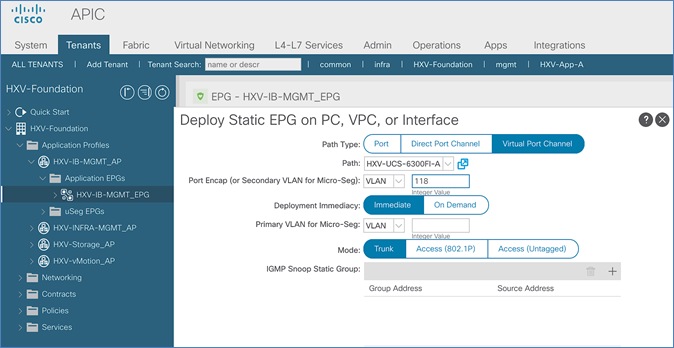
5. Click Submit.
6. Repeat steps 1-5 to bind the EPG to the VLAN on the second vPC going to the second UCS Fabric Interconnect in the same UCS domain.
7. Repeat steps 1-5 for the second UCS domain in the HyperFlex stretched cluster. The resulting bindings for this network are as shown below.
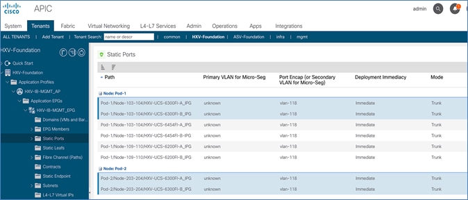
Create Static Binding for vMotion to HyperFlex Stretched Cluster
Follow the procedures outlined in this section to statically bind the vMotion EPG to the corresponding vMotion VLAN on the vPC interfaces going to the UCS Domains in the HyperFlex stretched cluster.
Setup Information
· Tenant: HXV-Foundation
· Application Profile: HXV-vMotion_AP
· EPG: HXV-vMotion_EPG
· Static Paths: HXV-UCS_6300FI-A_IPG, HXV-UCS_6300FI-B_IPG
· VLAN: 3018
Deployment Steps
1. Use a browser to navigate to the APIC GUI. Log in using the admin account.
2. From the top navigation menu, select Tenants > HXV-Foundation. If you do not see this tenant in the top navigation menu, select Tenants > ALL TENANTS and double-click on HXV-Foundation.
3. From the left navigation pane, select and expand Tenant HXV-Foundation > Application Profiles > HXV-vMotion_AP > Application EPGs > HXV-vMotion_EPG. Right-click and select Deploy Static EPG on PC, VPC or Interface.
4. In the Deploy Static EPG on PC, VPC or Interface pop-up window, for Path Type, select Virtual Port Channel. For the Path, select the vPC to the first UCS Fabric Interconnect from the drop-down list. For the Port Encap, specify the VLAN ID for the vMotion EPG. For the Deployment Immediacy, select Immediate.
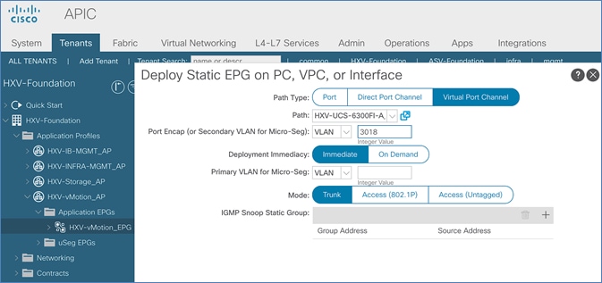
5. Click Submit.
6. Repeat steps1-5 to bind the EPG to the vPC going to the second UCS Fabric Interconnect in the same UCS domain.
7. Repeat steps1-5 for the second UCS domain in the HyperFlex stretched cluster. The resulting bindings for this network are as shown below.
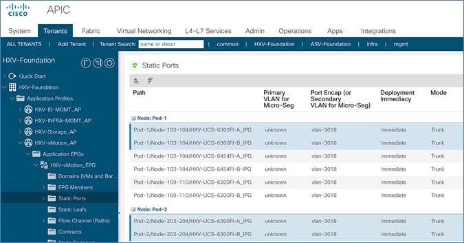
Configure ACI Fabric for Storage Data Traffic on HyperFlex Stretched Cluster
The configuration in this section will provide connectivity for storage data traffic through the ACI fabric. This storage data network will be used by the nodes in the HyperFlex stretch cluster that are distributed across the ACI Multi-Pod fabric. ESXi hosts also use this network to access storage data provided by the HyperFlex cluster.
Create Bridge Domain for Storage Data Traffic on HyperFlex Stretched Cluster
To create a Bridge Domain for storage data traffic, follow these steps:
Setup Information
· Tenant: HXV-Foundation
· VRF: HXV-Foundation_VRF
· Bridge Domain: HXV-CL1-Storage_BD
Deployment Steps
1. Use a browser to navigate to the APIC GUI. Log in using the admin account.
2. From the top navigation menu, select Tenants > HXV-Foundation. If you do not see this tenant in the top navigation menu, select Tenants > ALL TENANTS and double-click on HXV-Foundation.
3. From the left navigation pane, expand and select Tenant HXV-Foundation > Networking > Bridge Domains. Right-click and select Create Bridge Domain.
4. In the Create Bridge Domain wizard, specify a Name for the bridge domain. For VRF, select the previously created VRF from the drop-down list. For Forwarding, select Custom from the drop-down list. For L2 Unknown Unicast, select Flood from the drop-down list. ARP Flooding should now show up as enabled.
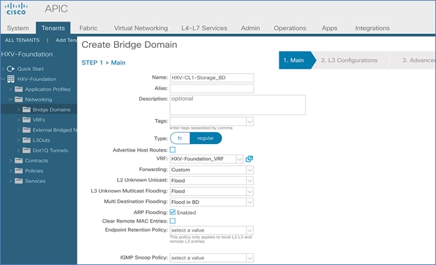
5. Click Next.
6. In the L3 Configurations section, disable Unicast Routing (optional), for EP Move Detection Mode, select the checkbox to enable GARP based detection. See Review/Enable ACI Fabric Settings section for more details.
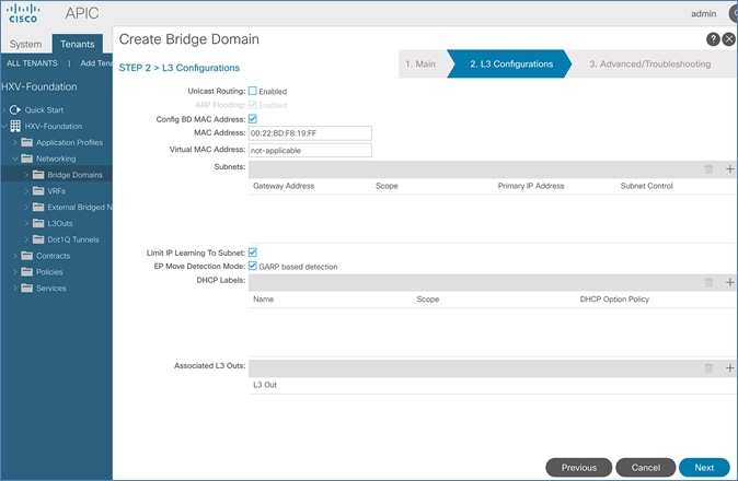
7. Click Next. Skip the Advanced/Troubleshooting section. Click Finish to complete.
Create Application Profile for Storage Data Traffic on HyperFlex Stretched Cluster
The application profile for HyperFlex storage data traffic is the same for all HyperFlex clusters in this design. Therefore, the HyperFlex stretched Cluster will use the same profile (HXV-Storage_AP) that was created for the HyperFlex Management cluster in the previous section.
Create EPG for Storage Data Traffic on HyperFlex Stretched Cluster
To create an EPG for storage data traffic on HyperFlex stretched cluster, follow these steps:
Setup Information
· Tenant: HXV-Foundation
· Application Profile: HXV-Storage_AP
· Bridge Domain: HXV-CL1-Storage_BD
· EPG: HXV-CL1-StorData_EPG
Deployment Steps
1. Use a browser to navigate to the APIC GUI. Log in using the admin account.
2. From the top navigation menu, select Tenants > HXV-Foundation. If you do not see this tenant in the top navigation menu, select Tenants > ALL TENANTS and double-click on HXV-Foundation.
3. From the left navigation pane, select and expand Tenant HXV-Foundation > Application Profiles > HXV-Storage_AP. Right-click and select Create Application EPG.
4. In the Create Application EPG pop-up window, specify a Name for the EPG. For Bridge Domain, select the previously created Bridge Domain.

5. Click Finish.
Associate EPG for Storage Data Traffic with Cisco UCS Domain
To associate the HyperFlex Storage EPG with UCS Domain, follow these steps:
Setup Information
· Tenant: HXV-Foundation
· Application Profile: HXV-Storage_AP
· EPG: HXV-CL1-StorData_EPG
· Domain: HXV-UCS_Domain
Deployment Steps
1. Use a browser to navigate to the APIC GUI. Log in using the admin account.
2. From the top navigation menu, select Tenants > HXV-Foundation. If you do not see this tenant in the top navigation menu, select Tenants > ALL TENANTS and double-click HXV-Foundation.
3. From the left navigation pane, select and expand Tenant HXV-Foundation > Application Profiles > HXV-Storage_AP > Application EPGs > HXV-CL1-StorData_EPG. Right-click and select Add L2 External Domain Association.
4. In the Add L2 External Domain Association pop-up window, select the previously created domain.
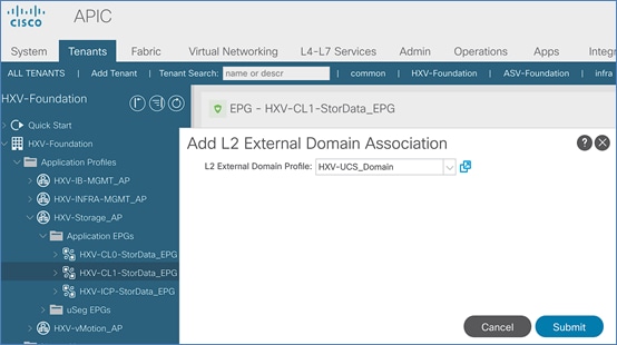
5. Click Submit.
Create Static Binding for Storage Data Traffic to UCS Domain for HyperFlex Stretched Cluster
Follow the procedures outlined in this section to statically bind the HyperFlex storage data EPG to the corresponding storage data VLAN on the vPC interfaces going to the UCS Domains in the HyperFlex stretched cluster.
Setup Information
· Tenant: HXV-Foundation
· Application Profile: HXV-Storage_AP
· EPG: HXV-CL1-StorData_EPG
· Static Paths: HXV-UCS_6300FI-A_IPG, HXV-UCS_6300FI-B_IPG
· VLAN: 3218
Deployment Steps
1. Use a browser to navigate to the APIC GUI. Log in using the admin account.
2. From the top navigation menu, select Tenants > HXV-Foundation. If you do not see this tenant in the top navigation menu, select Tenants > ALL TENANTS and double-click HXV-Foundation.
3. From the left navigation pane, select and expand Tenant HXV-Foundation > Application Profiles > HXV-Storage_AP > Application EPGs > HXV-CL1-StorData_EPG. Right-click and select Deploy Static EPG on PC, VPC or Interface.
4. In the Deploy Static EPG on PC, VPC or Interface pop-up window, for Path Type, select Virtual Port Channel. For the Path, select the vPC to the first UCS Fabric Interconnect from the drop-down list. For the Port Encap, specify the VLAN ID for the storage data EPG. For the Deployment Immediacy, select Immediate.
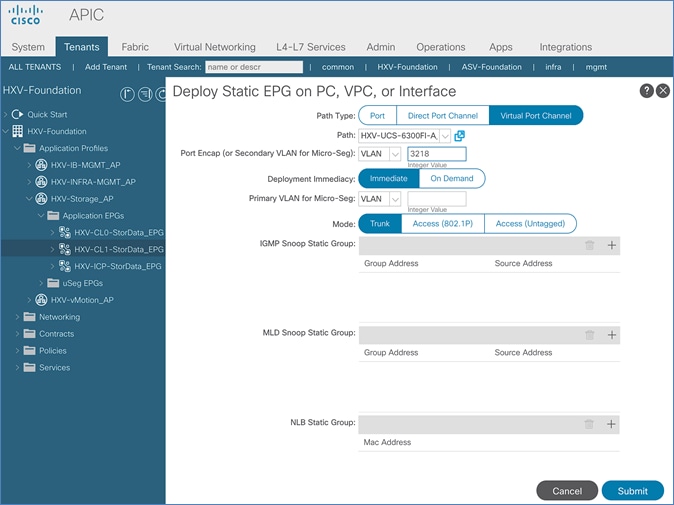
5. Click Submit.
6. Repeat steps 1-5 to bind the EPG to the vPC going to the 2nd UCS Fabric Interconnect in the same UCS domain.
7. Repeat steps 1-5 for the second UCS domain in the HyperFlex stretched cluster. The resulting bindings for this network are as shown below.
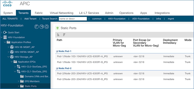
Install HyperFlex Stretched Cluster (Applications) using HyperFlex Installer VM
In this section, the installation of a (4+4) node HyperFlex stretched cluster is explained. This cluster is deployed using an on-premise installer. A HyperFlex standard cluster for Management, covered in an earlier section, was installed using Cisco Intersight.
![]() Screenshots in this section are from a previous release of this CVD. For this CVD, the testbed environment for the older CVD was upgraded and re-deployed. Therefore, any screenshots showing the initial install and setup of the fabric or the cluster are based on the previous CVD release.
Screenshots in this section are from a previous release of this CVD. For this CVD, the testbed environment for the older CVD was upgraded and re-deployed. Therefore, any screenshots showing the initial install and setup of the fabric or the cluster are based on the previous CVD release.
![]() Cisco Intersight currently does not support the installation of HyperFlex stretched clusters.
Cisco Intersight currently does not support the installation of HyperFlex stretched clusters.
The HyperFlex stretched cluster in this design is intended for application virtual machines and will be referred to as the Applications Cluster. The Management cluster on the other hand is intended for virtual machines that provide management and other infrastructure services to Application clusters and other HyperFlex clusters attached to the same ACI Multi-Pod fabric.
Similar to Cisco Intersight installation, the HyperFlex installer virtual machine will configure Cisco UCS policies, templates, service profiles, and settings, as well as assigning IP addresses to the HX servers that come from the factory with ESXi hypervisor software preinstalled. The installer will deploy the HyperFlex controller virtual machines and software on the nodes, add the nodes to VMware vCenter managing the HX Cluster, and finally create the HyperFlex cluster and distributed filesystem. The setup is done through a deployment wizard by providing the necessary information.
The deployment of a HyperFlex stretched cluster explained in this section consists of the following high-level steps.
· Configure Site 1 (Wizard)
· Configure Site 2 (Wizard)
· Deploy Witness Virtual Machine in a third Site (OVA)
· Create Cluster (Wizard)
· Verify Setup
Prerequisites
The prerequisites necessary for installing a HyperFlex stretched cluster from Cisco Intersight is as follows:
1. Reachability from HyperFlex Installer to the out-of-band management interfaces on Fabric Interconnects that the HyperFlex system being deployed connects to. This provides the installer access to Cisco UCS Manager.
2. Reachability from HyperFlex Installer to the out-of-band management (CIMC) interfaces on the servers, reachable via the Fabric Interconnects’ management interfaces. This network (ext-mgmt) should be in the same subnet as the Fabric Interconnect management interfaces.
3. ACI Multi-Pod Fabric setup to enable connectivity between HyperFlex Installer and infrastructure services necessary for deploying a HyperFlex stretched cluster. This includes access to NTP, AD/DNS, VMware vCenter and Witness Virtual machines. In this design, these services are either in the Management HyperFlex cluster connected to the same ACI Multi-Pod fabric or in an existing non-ACI network that is accessible through the Shared L3Out setup between ACI Multi-Pod fabric and the existing network
4. Reachability from HyperFlex Installer to the ESXi in-band management interface of the hosts in the HyperFlex cluster being installed.
5. Reachability from HyperFlex Installer to the VMware vCenter Server that will manage the HyperFlex cluster(s) being deployed.
![]() The VMware vCenter Virtual Machine must be hosted on a separate virtualization environment and should not be on the HyperFlex cluster being deployed.
The VMware vCenter Virtual Machine must be hosted on a separate virtualization environment and should not be on the HyperFlex cluster being deployed.
6. Reachability from HyperFlex Installer to the DNS server(s) for use by the HyperFlex cluster being installed.
7. Reachability from HyperFlex Installer to the NTP server(s) for use by the HyperFlex cluster being installed.
8. ACI Multi-Pod Fabric setup to enable connectivity to HyperFlex cluster networks - ESXi and Storage Controller management, ESXi and Storage Data networks, vMotion and Application VM networks.
9. Reachability from VMware vCenter to ESXi and Storage Controller Management networks.
10. Enable the necessary ports to install HyperFlex. For more information, see Networking Ports section in Appendix A of the HyperFlex Hardening Guide: https://www.cisco.com/c/dam/en/us/support/docs/hyperconverged-infrastructure/hyperflex-hx-data-platform/HX-Hardening_Guide_v3_5_v12.pdf
11. Review the Pre-installation Checklist for Cisco HX Data Platform: https://www.cisco.com/c/en/us/td/docs/hyperconverged_systems/HyperFlex_HX_DataPlatformSoftware/HyperFlex_Preinstall_Checklist/b_HX_Data_Platform_Preinstall_Checklist.html
Setup Information
The setup information used in this design to install a HyperFlex stretched cluster is provided below.
The following are the services in the Management HyperFlex Cluster:
· Installer VM IP Address: 10.10.167.248
The following are the services in the Existing non-ACI Network:
· VMware vCenter VM IP Address: 10.99.167.240
· Witness VM IP Address: 10.99.167.248
Site 1 Information
Table 67 Site 1 – Credentials
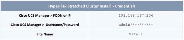
Table 68 Site 1 – UCSM Configuration
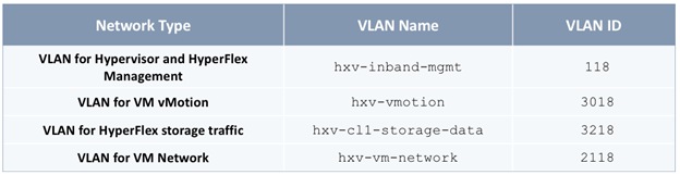
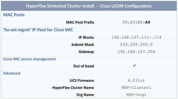
Table 69 Site 1 – Hypervisor Configuration
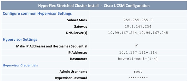
Site 2 Information
Table 70 Site 2 – Credentials
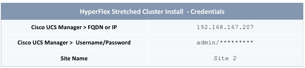
Table 71 Site 2 – UCSM Configuration
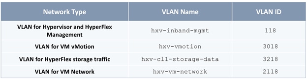
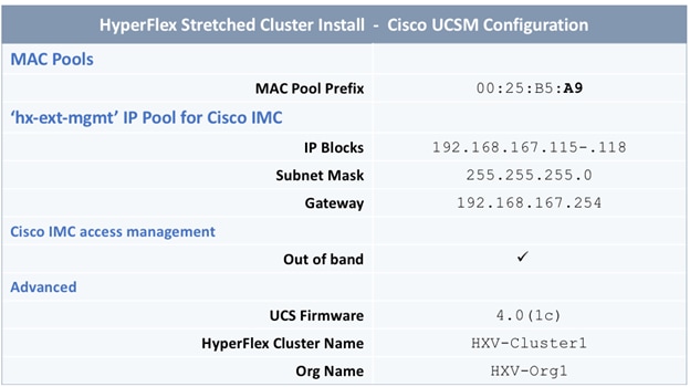
Table 72 Site 2 – Hypervisor Configuration
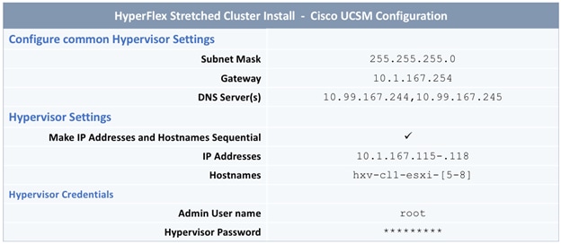
Cluster Information
Table 73 Cluster – Credentials
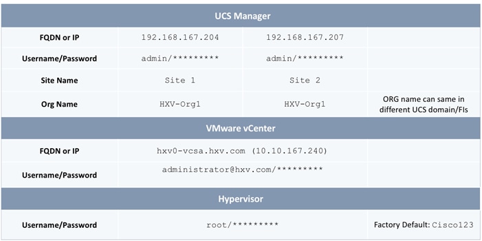
Table 74 Cluster – IP Addresses
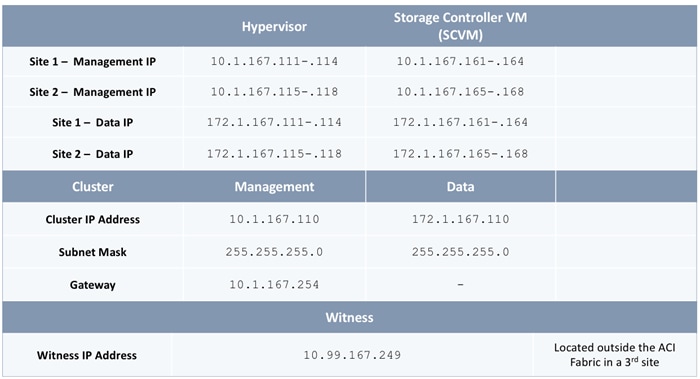
Table 75 Cluster Configuration
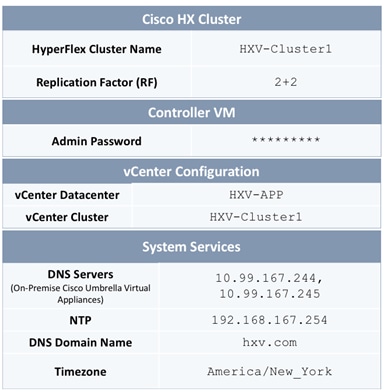
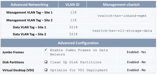
Deployment Steps
To deploy a HyperFlex stretched cluster across two sites interconnected by an ACI Multi-Pod fabric, complete the steps outlined in this section. The HyperFlex servers are connected to a separate pair of Cisco UCS Fabric Interconnects in each site.
Verify Server Status in Site 1 and Site 2 Before HyperFlex Installation
Before starting the HyperFlex installation process that will create the service profiles and associate them with the servers, you must verify that the servers in both Cisco UCS domains have finished their discovery process and are in the correct state.
To verify the server status in Site 1 and Site 2, follow these steps:
1. Use a browser to navigate to the Cisco UCS Manager in the first HyperFlex stretched cluster site (Site 1). Log in using the admin account.
2. From the left navigation pane, click the Equipment icon.
3. Navigate to All > Equipment. In the In the right windowpane, click the Servers tab.
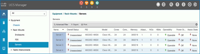
4. For the Overall Status, the servers should be in an Unassociated state. The servers should also be in an Operable state, powered Off and have no alerts with no faults or errors.
5. Repeat steps 1-4 for the Hyperflex nodes and Cisco UCS Manager in the second HyperFlex stretched cluster site (Site 2).
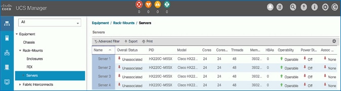
6. The servers in both sites are now ready for installing the HyperFlex Data Platform Software.
Access the HyperFlex Installer
To access the HyperFlex installer virtual machine, follow these steps:
1. Use a web browser to navigate to the IP address of the installer virtual machine. Click accept or continue to bypass any SSL certificate errors.
2. At the login screen, enter the username and password. The default username is: root. Password is either the default password (Cisco123) or whatever it was changed to after the OVA was deployed. Check the box for accepting terms and conditions. Verify the version of the installer – see lower right-hand corner of the login page.
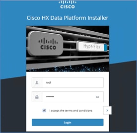
3. Click Login.
4. You should now be forwarded to the HyperFlex Installer Workflow page where you can install a new Standard Cluster, Stretch Cluster, Edge Cluster or expand an existing cluster. In this CVD, the installer virtual machine is used to deploy a HyperFlex stretched cluster.
Configure Site 1 from Deployment Wizard
To configure the first site (Site 1) in the stretched cluster, follow these steps:
1. From the HyperFlex Installer/Configuration Workflow page, for the Select a Workflow, click Create Cluster and from the drop-down list, select Stretch Cluster.
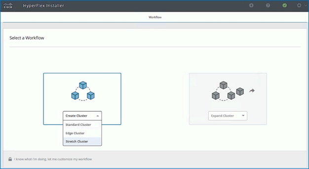
2. In the Credentials screen, select the radio button for Configure Site. For Site 1, specify the Cisco UCS Manager Hostname or IP address, the log in credentials and the Site Name (Site 1). The site name will be the name of the physical site in the Cisco HyperFlex Connect used to manage the cluster.
![]() If you have a JSON configuration file saved from a previous attempt to configure Site 1, you may click Select a File from the box on the right side of the window to select the JSON configuration file and click Use Configuration to populate the fields for configuring this site. The installer does not save passwords.
If you have a JSON configuration file saved from a previous attempt to configure Site 1, you may click Select a File from the box on the right side of the window to select the JSON configuration file and click Use Configuration to populate the fields for configuring this site. The installer does not save passwords.
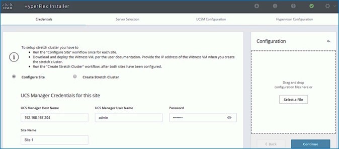
3. Click Continue.
4. In the Server Selection screen, select the unassociated servers that should be part of Site 1 in the stretched cluster.
![]() The Fabric Interconnect ports that connect to HyperFlex servers were enabled in the Solution Deployment – Setup Cisco UCS Domains section. You can also choose to enable it here by clicking on Configure Server Ports at the top. However, the servers will go through a discovery process that takes a significant amount of time and you will not have control of the server number order.
The Fabric Interconnect ports that connect to HyperFlex servers were enabled in the Solution Deployment – Setup Cisco UCS Domains section. You can also choose to enable it here by clicking on Configure Server Ports at the top. However, the servers will go through a discovery process that takes a significant amount of time and you will not have control of the server number order.
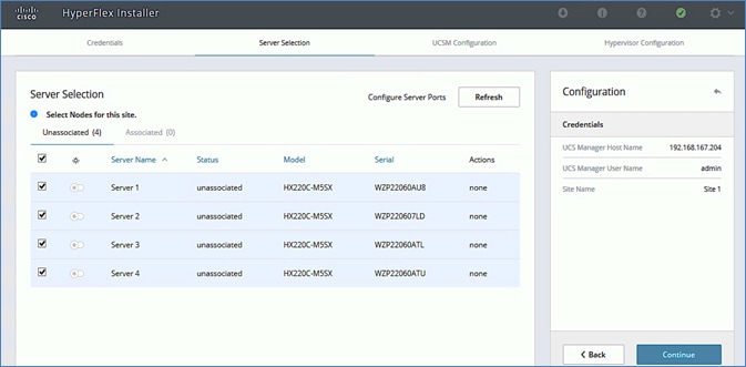
5. Click Continue.
6. In the UCSM Configuration screen, specify the UCSM related configuration for Site 1 as shown below.
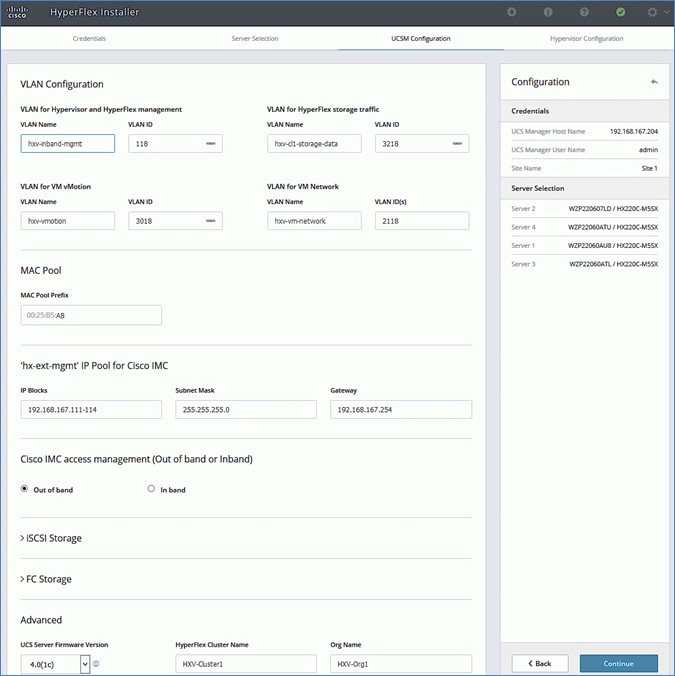
7. Enter the VLAN Names and VLAN IDs that are to be created in Cisco UCS. Multiple VLAN IDs can be specified for the (guest) virtual machine networks.
![]() In this design, the VMware virtual switch that will be created by the Installer for the (guest) virtual machine networks will be migrated to a Cisco ACI controlled Cisco AVE and the VLANs will be dynamically allocated. For this reason, it is not necessary to configure more than one VLAN for the virtual machine network. However, at least one VLAN is required in order to do other configuration for the virtual machine networks such as creating uplink vNICs in Cisco UCS Manager and creating appropriate QoS policies for virtual machine traffic.
In this design, the VMware virtual switch that will be created by the Installer for the (guest) virtual machine networks will be migrated to a Cisco ACI controlled Cisco AVE and the VLANs will be dynamically allocated. For this reason, it is not necessary to configure more than one VLAN for the virtual machine network. However, at least one VLAN is required in order to do other configuration for the virtual machine networks such as creating uplink vNICs in Cisco UCS Manager and creating appropriate QoS policies for virtual machine traffic.
8. For the MAC Pool prefix, specify the 4th byte (for example: 00:25:B5:A8). This prefix must be unique.
9. For the ‘hx-ext-mgmt’ IP Pool for Cisco IMC, specify a unique IP address range, subnet mask and gateway to be used by the CIMC interfaces of the servers in this HX cluster.
10. For the UCS Firmware Version, select the version of firmware to be loaded on servers in Site 1. The drop-down list shows the versions currently available on Cisco UCS Manager in Site 1.
11. For the HyperFlex Cluster, for HyperFlex Cluster Name, specify a name. For the Org Name, specify a unique name. The cluster names in both sites should be the same since both sites are part of a single cluster. The organization name can be the same in both sites of the stretched cluster but only because they’re in different UCS domains.
![]() When deploying additional clusters in the same UCS domain, change the VLAN names (even if the VLAN IDs are same), MAC Pool prefix, Cluster Name and Org Name so as to not overwrite the original cluster.
When deploying additional clusters in the same UCS domain, change the VLAN names (even if the VLAN IDs are same), MAC Pool prefix, Cluster Name and Org Name so as to not overwrite the original cluster.
12. Click Continue.
13. In the Hypervisor Configuration screen, specify the ESXi Management IP Addresses and Gateway information for the ESXi hosts in Site 1 as shown below. The default Hypervisor credentials for factory-installed nodes are: root with a password of Cisco123. The IP addresses will be assigned to the ESXi hosts via Serial over Lan (SoL) from Cisco UCS Manager.
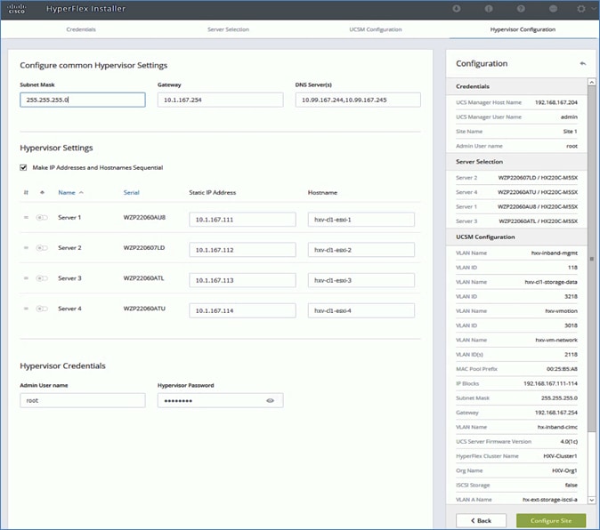
14. Click Configure Site to start configuring Site 1. The wizard will step through the configuration stages and provide the status for specific configuration completed as shown below:
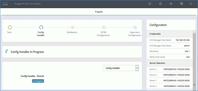
If the configuration is successful, you will see a screen similar to the one shown below:
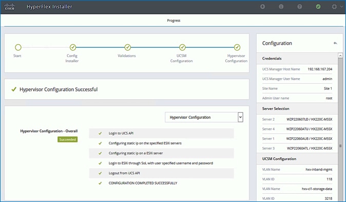
15. Export the Site 1 configuration by clicking the down arrow icon in the top right of the screen. Click OK to save the configuration to a JSON file. This file can be used to rebuild the same cluster in the future, and as a record of the configuration options and settings used during the installation.

16. Proceed to the next section to Configure Site 2.
Configure Site 2 from Deployment Wizard
To configure the second site (Site 2) in the stretched cluster, follow these steps:
1. From the HyperFlex Installer/Configuration wizard, go to the wheel icon in the top right of the window and select Configure Site from the drop-down list.
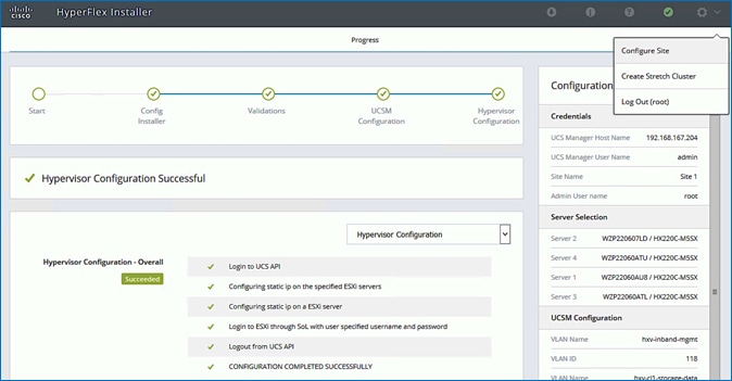
2. In the Credentials screen, select the radio button for Configure Site. For Site 2, specify the Cisco UCS Manager Hostname or IP address, the log in credentials and the Site Name (Site 2). The site name will be the name of the physical site in the Cisco HyperFlex Connect used to manage the cluster.
![]() If you have a JSON configuration file saved from a previous attempt to configure Site 2, you may click Select a File from the box on the right side of the window to select the JSON configuration file and click Use Configuration to populate the fields for configuring this site. Installer does not save passwords.
If you have a JSON configuration file saved from a previous attempt to configure Site 2, you may click Select a File from the box on the right side of the window to select the JSON configuration file and click Use Configuration to populate the fields for configuring this site. Installer does not save passwords.
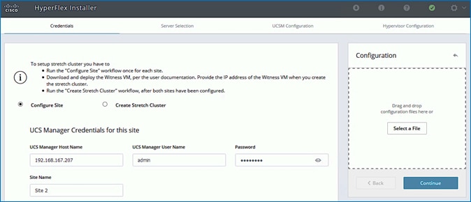
3. Click Continue.
4. In the Server Selection screen, select the servers that should be part of Site 2 in the stretched cluster.
![]() The Fabric Interconnect ports that connect to HyperFlex servers were enabled in the Solution Deployment – Setup Cisco UCS Domains section. You can also choose to enable it here by clicking Configure Server Ports at the top. However, the servers will go through a discovery process that takes a significant amount of time and you will not have control of the server number order.
The Fabric Interconnect ports that connect to HyperFlex servers were enabled in the Solution Deployment – Setup Cisco UCS Domains section. You can also choose to enable it here by clicking Configure Server Ports at the top. However, the servers will go through a discovery process that takes a significant amount of time and you will not have control of the server number order.
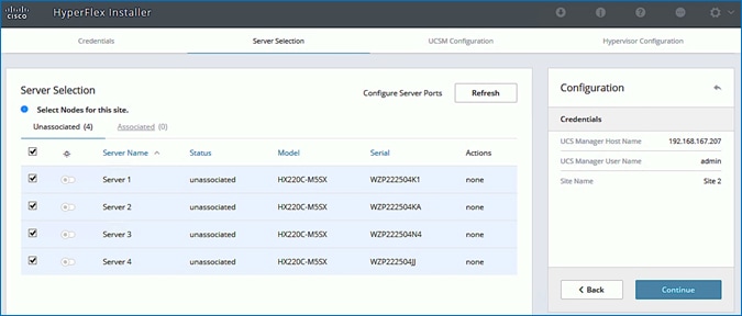
5. Click Continue.
6. In the UCSM Configuration screen, specify the UCSM related configuration for Site 2 as shown below:
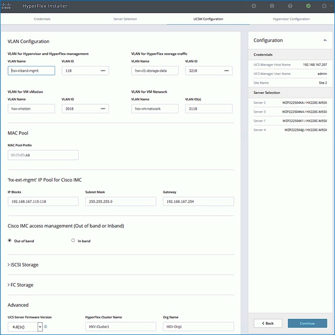
7. Enter the VLAN Names and VLAN IDs that are to be created in Cisco UCS. Multiple VLAN IDs can be specified for the (guest) virtual machine networks.
![]() In this design, the VMware virtual switch that will be created by the Installer for the (guest) virtual machine networks will be migrated to a Cisco ACI controlled Cisco AVE and the VLANs will be dynamically allocated. For this reason, it is not necessary to configure more than one VLAN for the virtual machine network. However, at least one VLAN is required in order to do other configuration for the virtual machine networks such as creating uplink vNICs in Cisco UCS Manager and creating appropriate QoS policies for VM traffic.
In this design, the VMware virtual switch that will be created by the Installer for the (guest) virtual machine networks will be migrated to a Cisco ACI controlled Cisco AVE and the VLANs will be dynamically allocated. For this reason, it is not necessary to configure more than one VLAN for the virtual machine network. However, at least one VLAN is required in order to do other configuration for the virtual machine networks such as creating uplink vNICs in Cisco UCS Manager and creating appropriate QoS policies for VM traffic.
8. For the MAC Pool prefix, specify the 4th byte, for example: 00:25:B5:A9. This prefix must be unique.
9. For the ‘hx-ext-mgmt’ IP Pool for Cisco IMC, specify a unique IP address range, subnet mask and gateway to be used by the CIMC interfaces of the servers in this site.
10. For the UCS Firmware Version, select the version of firmware to be loaded on servers in Site 2. The drop-down list shows the versions currently available on Cisco UCS Manager in Site 2.
11. For the HyperFlex Cluster, specify a name. For the Org Name, specify a unique name. The cluster names in both sites should be the same since both sites are part of a single cluster. The organization name can be the same in both sites of the stretched cluster but only because they’re in different UCS domains.
![]() When deploying additional clusters in the same UCS domain, change the VLAN names (even if the VLAN IDs are same), MAC Pool prefix, Cluster Name and Org Name so as to not overwrite the original cluster information.
When deploying additional clusters in the same UCS domain, change the VLAN names (even if the VLAN IDs are same), MAC Pool prefix, Cluster Name and Org Name so as to not overwrite the original cluster information.
12. Click Continue.
13. In the Hypervisor Configuration screen, specify the ESXi Management IP Addresses and Gateway information for the ESXi hosts in Site 2 as shown below. The default Hypervisor credentials for factory-installed nodes are: root with a password of Cisco123. The IP addresses will be assigned to the ESXi hosts via Serial over Lan (SoL) from Cisco UCS Manager.
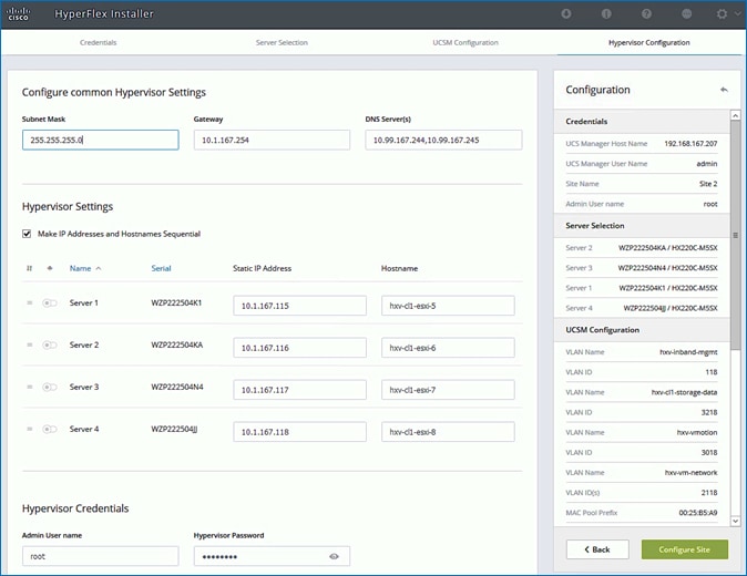
14. Click Configure Site to start configuring Site 2. The wizard will step through the configuration stages and provide the status for specific configuration completed as shown below:
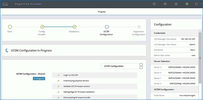
15. If the configuration is successful, you will see a screen similar to the one below.
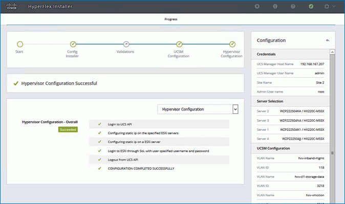
16. Export the Site 2 configuration by clicking the down arrow icon in the top right of the screen. Click OK to save the configuration to a JSON file. This file can be used to rebuild the same cluster in the future, and as a record of the configuration options and settings used during the installation.

17. Proceed to the next section to Deploy Witness Virtual Machine at a third site.
Deploy Witness Virtual Machine in a Third Site
To achieve quorum in a HyperFlex stretched cluster, a Witness virtual machine is necessary. The Witness virtual machine should be deployed in a third site and must be reachable from all sites in a HyperFlex stretched cluster. In this design, the Witness virtual machine is deployed in an existing network outside the ACI Multi-Pod Fabric.
Table 76 Setup Information
| Witness VM - IP Address/Subnet Mask |
10.99.167.249/24 |
| Gateway |
10.99.167.254 (outside the ACI Fabric) |
| DNS |
10.99.167.244, 10.99.167.245 |
| NTP |
192.168.167.254 |
To deploy the Witness virtual machine for the HyperFlex stretched cluster, follow these steps:
1. Use a browser to navigate to the VMware vCenter server that will be used to deploy the Witness virtual machine will be deployed.
2. Click the vSphere Web Client of your choice. Log in using an Administrator account.
3. From the vSphere Web Client, navigate to Home > Hosts and Clusters.
4. From the left navigation pane, select the Datacenter > Cluster and right-click to select Deploy OVF Template….
5. In the Deploy OVF Template wizard, for Select Template, select Local file and click the Browse button to locate and open the HyperFlex-Witness-1.0.2.ova file, click the file and click Open. Click Next.
6. Modify the name of the virtual machine to be created if desired and click a folder location to place the virtual machine. Click Next.
7. Click a specific host or cluster to locate the virtual machine. Click Next.
8. After the file validation, review the details. Click Next.
9. Select a Thin provision virtual disk format, and the datastore to store the new virtual machine. Click Next.
10. Modify the network port group selection from the drop-down list in the Destination Networks column, choosing the network the witness VM will communicate on. Click Next.
11. Enter the static address settings to be used, fill in the fields for the Witness Node’s IP Address and Mask, DNS server, Default Gateway, and NTP Server info.
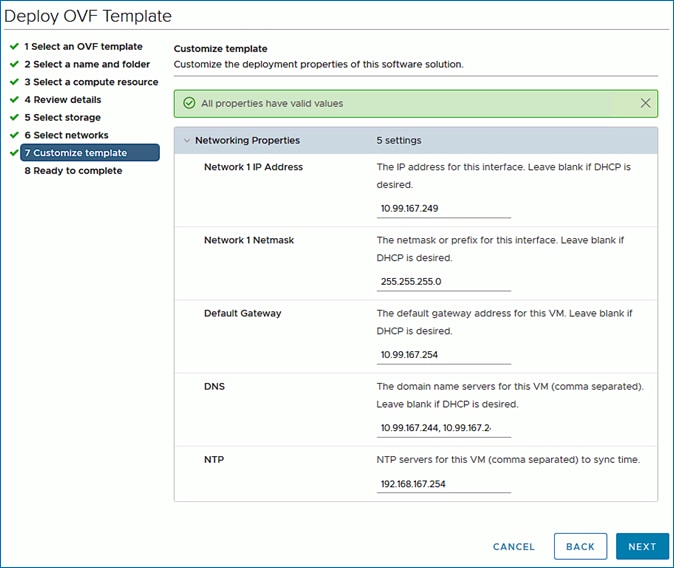
12. Click Next.
13. Review the final configuration and click Finish. The witness VM will take a few minutes to deploy, once it has deployed, power on the new VM.
14. Proceed to the next section to create a stretch HyperFlex cluster.
Create Stretch Cluster from Deployment Wizard
To create the stretched cluster using Site 1 and Site 2, follow these steps:
1. From the HyperFlex Installer/Configuration Wizard, go to the wheel icon in the top right of the window and select Create Stretch Cluster from the drop-down list.
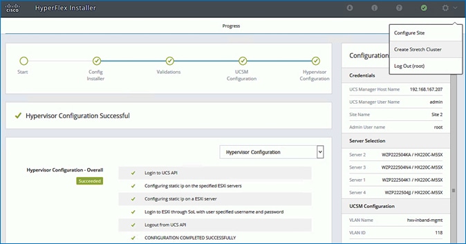
2. In the Credentials screen, select the radio button for Create Stretch Cluster. For Site 1 and Site 2, specify the Cisco UCS Manager Credentials (Hostname or IP address, username, and password), VMware vCenter Credentials (for the vCenter managing the stretch cluster), and Hypervisor Credentials as shown below.
![]() If you have a JSON configuration file saved from a previous attempt for Create Stretch Cluster, you may click Select a File from the box on the right side of the window to select the JSON configuration file and click Use Configuration to populate the fields for configuring this site. The installer does not save passwords.
If you have a JSON configuration file saved from a previous attempt for Create Stretch Cluster, you may click Select a File from the box on the right side of the window to select the JSON configuration file and click Use Configuration to populate the fields for configuring this site. The installer does not save passwords.
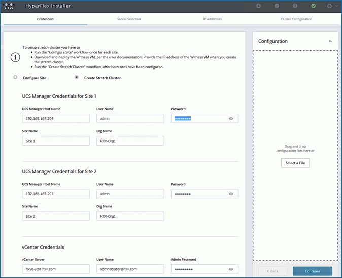
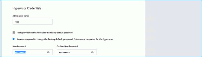
3. Click Continue.
4. In the Server Selection screen, select the servers from Site 1 and Site 2 that should be part of the stretched cluster.
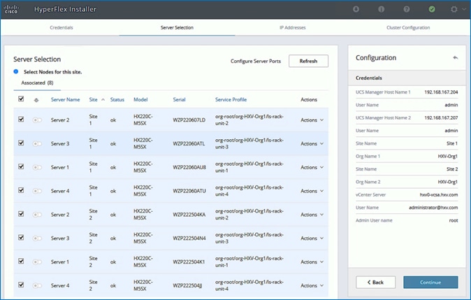
5. Click Continue.
6. In the IP Addresses screen, specify the IP addresses for the cluster (ESXi host and Storage Controller VM’s Management IP Addresses, ESXi host and Storage Controller VM’s Storage Data Network IP Addresses, Cluster IP Addresses for Management and Storage Data, Gateway for Management Subnet and Witness Node IP Address) as shown below.
![]() A default gateway is not required for the data network, as those interfaces normally will not communicate with any other hosts or networks, and the subnet can be non-routable.
A default gateway is not required for the data network, as those interfaces normally will not communicate with any other hosts or networks, and the subnet can be non-routable.
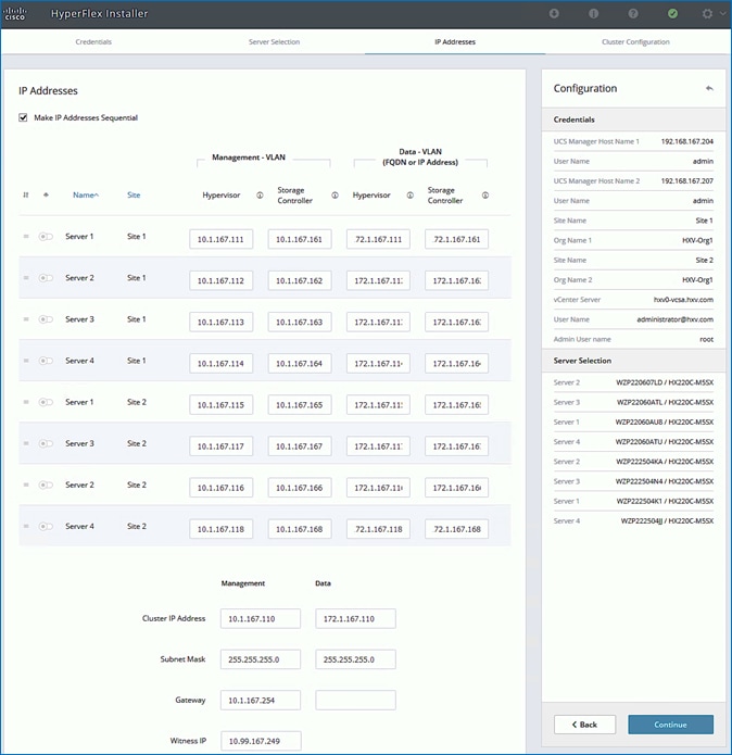
7. Click Continue.
8. In the Cluster Configuration screen, specify a name for the HyperFlex Cluster, the Replication Factor to use, Storage Controller VM (SCVM) Credentials, VMware vCenter configuration (Datacenter, Cluster), Services (DNS, NTP, Domain Name, Timezone) and Networking (Management, Storage Data, Jumbo Frames, and so on).
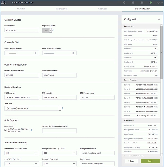
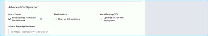
9. Click Start to start the creation of the stretched cluster. The wizard will step through the configuration stages and provide status for each stage. If the configuration is successful, you will see a screen similar to the one below:
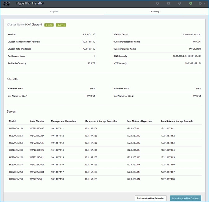
10. Export the cluster configuration by clicking the down arrow icon in the top right of the screen. Click OK to save the configuration to a JSON file. This file can be used to rebuild the same cluster in the future, and as a record of the configuration options and settings used during the installation.

11. Process to the next section to complete the post-installation tasks – run the post_install script to create the vMotion interfaces, additional guest virtual machine port groups (optional), and to enable HA and DRS in the cluster.
![]() For stretched clusters, it is very important to review the DRS Site Affinity rules to verify that it is setup correctly.
For stretched clusters, it is very important to review the DRS Site Affinity rules to verify that it is setup correctly.
Complete Post-Installation Tasks
When the installation is complete, additional best-practices and configuration can be implemented using a Cisco provided post-install script. The script should be run before deploying virtual machine workloads on the cluster. The script is executed from the Installer virtual machine and can do the following:
· License the hosts in VMware vCenter
· Enable HA/DRS on the cluster in VMware vCenter
· Suppress SSH/Shell warnings in VMware vCenter
· Configure vMotion in VMware vCenter
· Enables configuration of additional guest VLANs/port-groups
· Send test Auto Support (ASUP) email if enabled during the install process
· Perform HyperFlex Health check
To run the post-installation script, follow these steps:
1. SSH into a HyperFlex Installer virtual machine used to deploy the cluster. Log in using the admin (or root) account.
2. From the Controller virtual machine, run the command to execute the post-install script: post_install.py
3. Follow the on-screen prompts to complete the post-install configuration as shown below.
![]() Any VLANs created on the HyperFlex cluster and UCSM will need a corresponding configuration in the ACI fabric to enable forwarding for that VLAN within the ACI Fabric.
Any VLANs created on the HyperFlex cluster and UCSM will need a corresponding configuration in the ACI fabric to enable forwarding for that VLAN within the ACI Fabric.
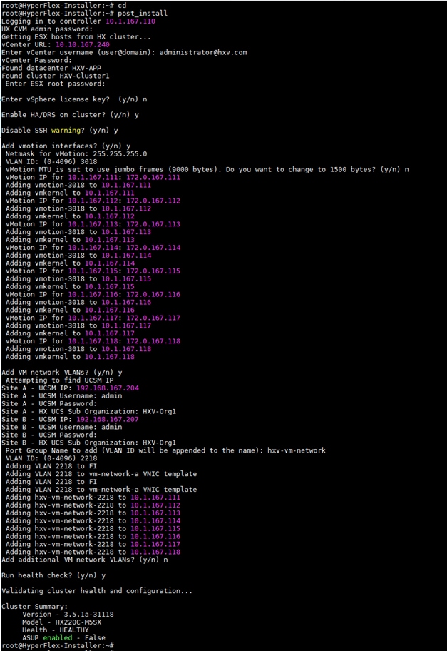
Enable Smart Licensing for Stretch HyperFlex Cluster
To enable licensing for the newly deployed HyperFlex stretched cluster, follow the procedures outlined in the Install HyperFlex Management Cluster.
Enable Syslog for Stretch HyperFlex Cluster
To prevent the loss of diagnostic information when a host fails, ESXi logs should be sent to a central location. Logs can be sent to the VMware vCenter server or to a separate syslog server.
Use a multi-exec tool (for example, MobaXterm) to simultaneously execute the same command on all servers in the cluster as shown below.
To configure syslog on ESXi hosts, follow these steps:
1. Log into the ESXi host through SSH as the root user.
2. Enter the following commands, replacing the IP address in the first command with the IP address of the vCenter or the syslog server that will receive the syslog logs.
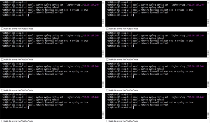
Manage Cluster using Cisco Intersight
Cisco Intersight provides a centralized dashboard with a single view of all Cisco UCS Domains, HyperFlex clusters and servers regardless of their location. New features and capabilities are continually being added over time. Please see the Cisco Intersight website for the latest information.
To manage the HyperFlex stretched cluster from Cisco Intersight, follow the procedures outlined in the Enable Cisco Intersight Cloud-Based Management section.
Manage Cluster using HyperFlex Connect
To manage the HyperFlex stretched cluster using HyperFlex Connect, follow these steps:
1. Open a web browser and navigate to the Management IP address of the HX cluster (for example, https://10.1.167.110). Log in using the admin account. Password should be same as the one specified for the Storage Controller virtual machine during the installation process.
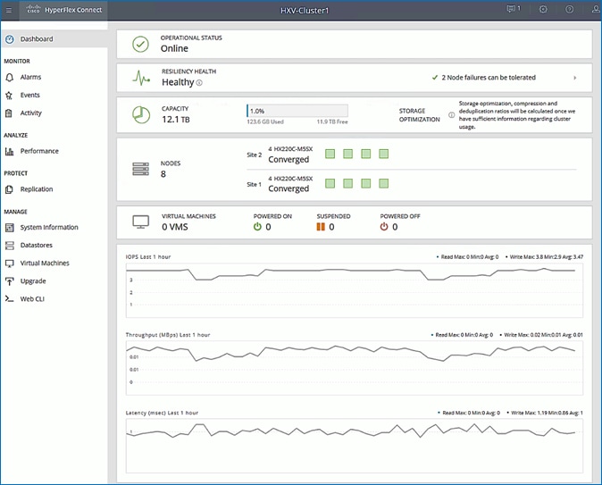
2. The Dashboard provides general information about the cluster’s operational status, health, Node failure tolerance, Storage Performance and Capacity Details and Cluster Size and individual Node health.
(Optional) Manage Cluster using VMware vCenter (through Plugin)
The Cisco HyperFlex vCenter Web Client Plugin can be deployed as a secondary tool to monitor and configure the HyperFlex cluster.
![]() This plugin is not supported in the HTML5 based VMware vSphere Client for vCenter.
This plugin is not supported in the HTML5 based VMware vSphere Client for vCenter.
To manage the HyperFlex cluster using the vCenter Web Client Plugin for vCenter 6.7, follow the procedures outlined in the Install HyperFlex Management Cluster section of this document.
Enable/Disable Auto-Support and Notifications
Auto-Support is enabled if specified during the HyperFlex installation. Auto-Support enables Call Home to automatically send support information to Cisco TAC, and notifications of tickets to the email address specified. If the settings need to be modified, they can be changed in the HyperFlex Connect HTML management webpage.
To change Auto-Support settings, follow the procedures outlined in the Install HyperFlex Management Cluster section of this document.
Create Datastores for Virtual Machines with Site Affinity
Datastores created in stretched clusters require a Site Affinity setting compared to datastores in standard clusters. Specifying a site association for the datastores ensures that all requests to read data from that datastore will be serviced by the nodes in that specific site, rather than by nodes in the remote site. When deploying Virtual Machines, the virtual machines should be configured to store their virtual disk files in a datastore at the same site as the virtual machine. The placement of the virtual machines using vSphere Dynamic Resource Scheduler (DRS) site affinity rules optimizes the performance in a stretched cluster, by ensuring proximity to the users that consume the services provided by the virtual machine.
To deploy a new datastore from HyperFlex Connect, follow the procedures outlined in the Install HyperFlex Management Cluster section of this document, however for stretched clusters, the Site Affinity needs to be specified as shown below:
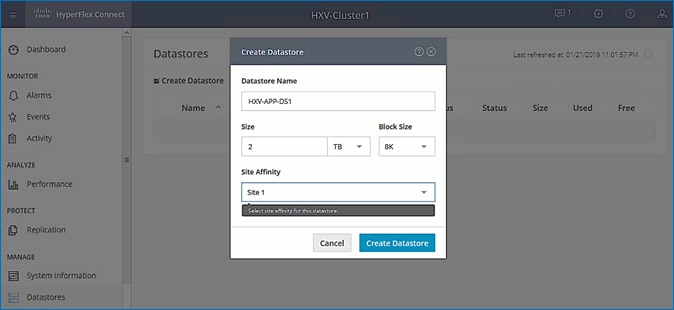
To validate the design, two datastores are created on the stretch cluster with Site Affinity to Site 1 (Pod-1) and Site 2 (Pod-2) as shown below:
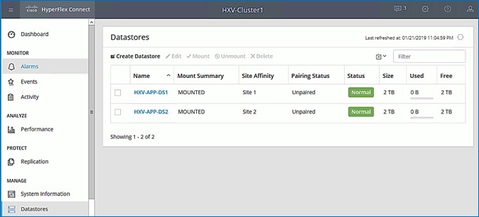
Configure vSphere DRS with Site Affinity
VMware vSphere Dynamic Resource Scheduler (DRS) must be configured with site affinity rules in order for the stretched cluster to operate in an optimal manner. Virtual machine placement across a stretched cluster uses these site affinity rules, in order to constrain virtual machines to only run on the nodes in their primary site during normal operation. The datastore that stores the virtual machine’s virtual disk files will also be associated with the same site. Site affinity rules and groups are automatically created during the installation, and the rules are created in such a manner that the virtual machines are allowed to restart and run in the other site in case of a site failure. When virtual machines are created, they are automatically placed into the virtual machine group associated with the site where they are running. This method helps to balance workloads across all of the nodes in both sites, while retaining the enhanced failover capability of a stretched cluster if an entire site was to go offline or otherwise fail.
The automatically created Host Groups and Virtual Machine Groups for each site are shown below:
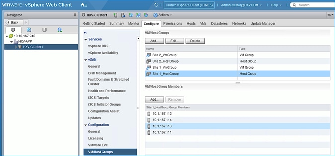
vSphere High Availability Recommendations
The VMware setup is critical for the operation of a HyperFlex stretched cluster. HyperFlex installation configures many VMware features that a stretched cluster requires such as vSphere HA, DRS, virtual machine and datastore host-groups, site-affinity, etc. In addition, customers should also enable the following vSphere HA settings in VMware vCenter:
· vSphere Availability: vSphere HA should be enabled but keep Proactive HA disabled
· Failure Conditions and responses:
- Enable Host Monitoring
- For Host Failure Response, select Restart VMs
- For Response for Host Isolation, select Power off and restart VMs
- For Datastore with PDL, select Power off and restart VMs
- For Datastore with PDL, select Power off and restart VMs (conservative)
- For VM Monitoring: Customer can enable this if they prefer. It is typically disabled.
· Admission Control: select Cluster resource percentage for Define host failover capacity by
· Datastore Heartbeats: Select Use datastores only from the specified list and select HyperFlex datastores in each site
· Advanced Settings:
- select False for das.usedefaultisolationaddress
- select an IP address in Site A for das.isolationaddress0
- select an IP address in Site B for das.isolationaddress1
· For additional recommendations, see Operating Cisco HyperFlex Data Platform Stretched Clusters white paper in the References section of this document.
Migrate Virtual Networking to VMware vDS on HyperFlex Application Cluster
This section configures the virtual networking for the virtual machines hosted on the Application cluster. APIC manages the virtual networking on this cluster through integration with VMware vCenter that manages the cluster. In this release of the CVD, the Applications cluster uses a VMware vDS as the virtual switch for VM networks. A Cisco AVE can also be used – Cisco AVE was used in the previous release of this CVD. The HyperFlex infrastructure networks (in-band management, storage data and vMotion networks) deployed by the HyperFlex Installer will remain on VMware vSwitch. The virtual networking uses VMware vDS as the virtual switch for the VMs hosted on the Application cluster. VMware vCenter that manages Application HyperFlex cluster is located in a third location outside the ACI Multi-Pod fabric, and reachable through the Shared L3Out from each Pod.
Setup Information
The setup information for migrating the default virtual networking from VMware vSwitch to VMware vDS is provided below:
· VLAN Name: HXV1-VMM_VLANs
· VLAN Pool: 1118-1128
· Virtual Switch Name: HXV1-vDS
· Associated Attachable Entity Profile: HXV-UCS_AAEP
· VMware vCenter Credentials: <Username/Password> for the vCenter managing this cluster
· VMware vCenter Credentials – Profile Name: Administrator
· VMware vCenter Managing the VMM Domain: hxv0-vcsa.hxv.com (10.99.167.240)
· DVS Version: vCenter Default
· VMware vCenter Datacenter: HXV-APP
· Default vSwitch for VM networks: vswitch-hxv-vm-network
· Uplinks on Default vSwitch for VM Networks: vmnic2, vmnic6
· Cisco UCS vNIC Templates for VM Networks: vm-network-a, vm-network-b
· vNIC Template QoS Policy: Gold
Deployment Steps
To enable APIC-controlled virtual networking for the Applications cluster, follow the procedures outlined in this section.
Create VLAN Pool for VMM Domain
To configure VLAN pools for use by VMs hosted on the Applications cluster, follow these steps:
1. Use a browser to navigate to the APIC GUI. Log in using the admin account.
2. From the top navigation menu, select Fabric > Access Policies.
3. From the left navigation pane, expand and select Pools > VLAN. Right-click and select Create VLAN Pool.
4. In the Create VLAN Pool pop-up window, specify a Name for the pool to use for port-groups on VMware vDS. For Allocation Mode, select Dynamic Allocation. For Encap Blocks, click on the [+] icon on the right side to specify a VLAN range.
5. In the Create Ranges pop-up window, specify a VLAN range for the pool. Leave other settings as is.
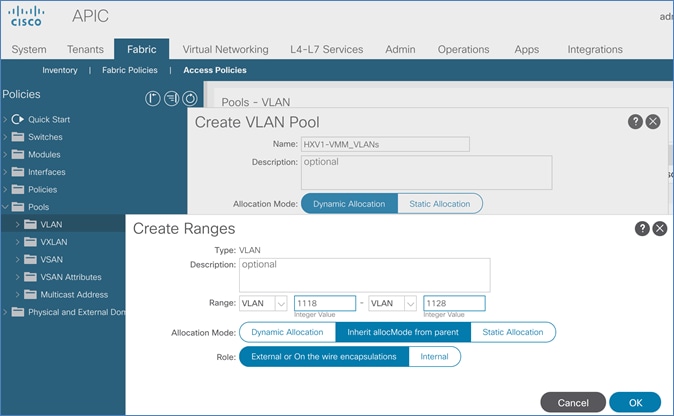
6. Click OK and then click Submit to complete.
Enable VMM Integration for HyperFlex Application Cluster
A new VMM domain must be configured Cisco ACI in order to deploy an APIC-controlled VMware vDS through VMware vCenter. The VMM domain will require a VLAN pool for use by port-groups corresponding to the EPGs in ACI. The pool should accommodate the number of EPGs published to the VMware vCenter domain in the form of port-groups. Pre-configured policies and statistics collection are also enabled for the new VMM domain.
To enable VMM integration for the Application HyperFlex cluster, follow these steps:
1. Use a browser to navigate to APIC’s Web GUI. Log in using the admin account.
2. From the top menu, navigate to Virtual Networking.
3. From the left navigation pane, select Quick Start.
4. From the right-window pane, click (VMware hypervisor) Create a vCenter Domain Profile.
5. In the Create vCenter Domain pop-up window, for the Virtual Switch Name, specify a name (for example, HXV1-vDS). This will be the name of the VMware vDS switch in VMware vCenter. For Virtual Switch, leave VMware vSphere Distributed Switch selected. For Associated Attachable Entity Profile, select the AAEP for the UCS domain that the VMM domain is hosted on. For VLAN Pool, select the previously created pool associated with this VMM domain from the drop-down list. Leave the other settings as is.
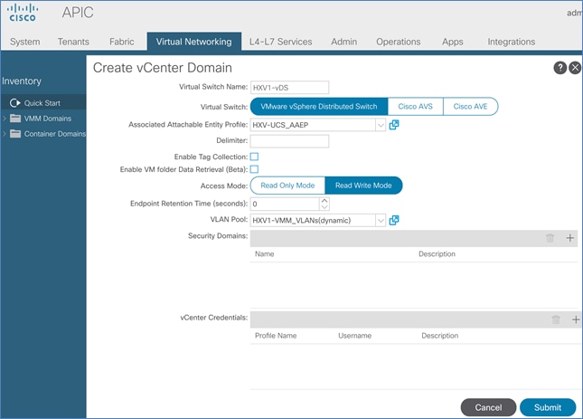
6. In the Create vCenter Domain window, scroll-down to vCenter Credentials and click the [+] icon on the right side to add a vCenter Account Profile.
7. In the Create vCenter Credential pop-up window, specify a Name for the credentials, along with the appropriate account Username and Password.
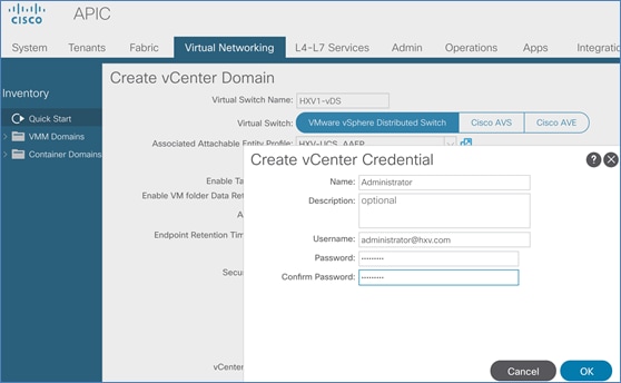
8. Click OK to close the Create vCenter Credential pop-up window. In the Create vCenter Domain window, scroll-down to vCenter and click the [+] icon on the right side to add a vCenter Controller.
9. In the Add vCenter Controller pop-up window, enter a Name (HXV0-VCSA) for the vCenter. For Host Name (or IP Address), enter the vCenter IP or Hostname. For DVS Version, leave it as vCenter Default. For Datacenter, enter the Datacenter name provisioned on the vCenter. Name is case-sensitive. For Associated Credential, select the vCenter credentials created in the last step (Administrator).
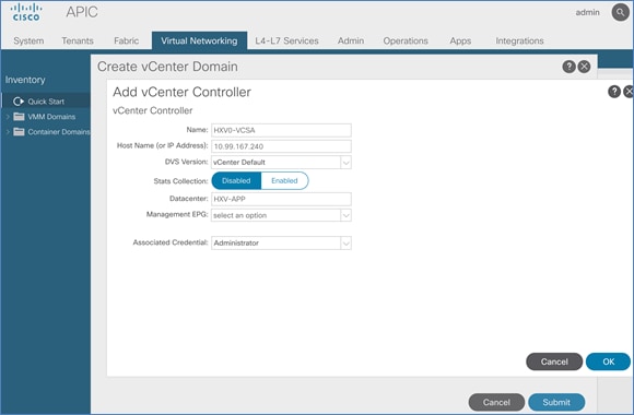
10. Click OK to close Add vCenter Controller window. In the Create vCenter Domain window, for Port Channel Mode, select MAC Pinning-Physical-NIC-load from the drop-down list. For vSwitch Policy, select LLDP.
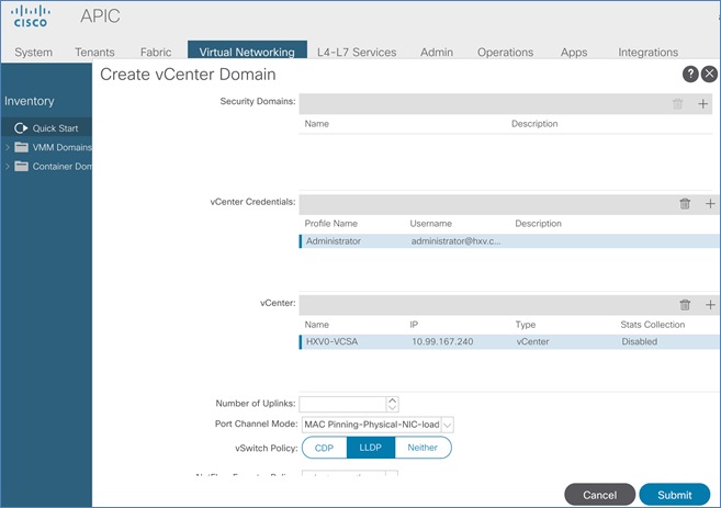
11. Click Submit to create the APIC managed vDS in VMware vCenter for the HyperFlex Applications cluster
12. Use a browser to navigate to the VMware vCenter server managing the HyperFlex Applications cluster. Select the vSphere Web Client of your choice. Log in using an Administrator account. Navigate to the data center for Applications and select the Networking tab from the left navigation window. Select Networks > Distributed Switches in the right windowpane to verify that the vDS switch was created and setup correctly.
Migrate HyperFlex ESXi Hosts to VMware vDS
To migrate HyperFlex ESXi Hosts in the Applications cluster to the newly created VMware vDS, the procedures used in the Management cluster can be used here as well – see Add HyperFlex ESXi Hosts to VMware vSphere vDS section for the detailed steps.
Now you are ready to deploy Virtual Machines on the HyperFlex cluster using Cisco AVE virtual leaf switches.
This section provides detailed procedures for onboarding multi-tier applications onto the Application cluster. Application virtual machines can be deployed in either data center in this active-active data center solution.
Deployment Overview
The high-level steps for deploying multi-tier applications on a Cisco HyperFlex cluster connected to a Cisco ACI Multi-Pod fabric are as follows:
1. Define ACI Constructs to enable forwarding for the new Application or Application group. This includes defining an Application Tenant, VRF, Bridge Domain and an Application Profile.
2. Define ACI End Point Groups for the new Application or Application group. A three-tier application could be deployed using three EPGs, for example, Web, App and Database EPGs, with each EPG representing an application tier. Each EPG can have one or more VMs.
3. Enable contracts to allow users to access the Application and for communication between different tiers of the application. Also, enable contracts to access the shared L3out for connectivity to outside networks and services.
4. Deploy application virtual machines on the Application HyperFlex cluster.
5. Add virtual machines to the port-group corresponding to the EPG.
In this section, a sample two-tier (Web, App) application is deployed in a dedicated tenant HXV-App-A. The Web and App Tier will be mapped to corresponding EPGs in the ACI fabric.
Prerequisites
· Integration with Virtual Machine Manager or VMware vCenter for virtual networking should be in place before onboarding applications as outlined in this section. As a part of this integration, a VLAN pool should also be pre-defined. VLANs from the VLAN pool will be assigned to Application EPGs such that when an EPG is defined in ACI, a corresponding port-group is created in the VMM domain. The application virtual machines, when deployed, can now be added to the corresponding port-group to enable connectivity through the ACI fabric.
· When a VLAN Pool is defined for VMM integration, the VLANs needs to be created in the UCS domain hosting the VMM domain. For the Application cluster in this design, the VLANs need to be enabled on both UCS domains that HyperFlex stretched cluster nodes connect to.
![]() If VLANs (hxv-vm-network) are specified during cluster install or as input to the post-install script, then these VLANs are automatically created and trunked on the Cisco UCS Fabric Interconnect uplinks, and on the virtual NICs (vNIC vm-network-a, vNIC vm-network-b) of each HyperFlex node.
If VLANs (hxv-vm-network) are specified during cluster install or as input to the post-install script, then these VLANs are automatically created and trunked on the Cisco UCS Fabric Interconnect uplinks, and on the virtual NICs (vNIC vm-network-a, vNIC vm-network-b) of each HyperFlex node.
Configure ACI constructs for Application Traffic
Follow the procedures outlined in this section to configure the ACI constructs (Tenant, VRF, Bridge Domain and Application Profile) for a new multi-tier application or application group.
Create Tenant and VRF for Application
To create Tenant and VRF for the application, follow these steps:
1. Use a browser to navigate to APIC’s Web GUI. Log in with the admin account.
2. From the top menu, select Tenants > Add Tenant.
3. In the Create Tenant pop-up window, specify a Name (for example, HXV-App-A).
4. For the VRF Name, enter a name for the only VRF in this Tenant (for example, HXV-App-A_VRF)
5. Leave the checkbox for Take me to this tenant when I click finish checked.
6. Click Submit to complete the configuration.
Configure Bridge Domains
At least one bridge domain is necessary to enable any forwarding. In this design, two bridge domains are used in the event that a customer will need to insert a firewall between one of the application tiers. Insertion and configuration of a firewall between tiers is outside the scope of this document. To create an internal versus an external bridge domain to enable the insertion of a firewall between application tiers, follow these steps:
1. Use a browser to navigate to APIC’s Web GUI. Login with the admin account.
2. From the top menu, select Tenants > HXV-App-A. If you do not see this tenant in the top navigation menu, select Tenants > ALL TENANTS and double-click on HXV-App-A.
3. In the left navigation pane, navigate to Tenant HXV-App-A > Networking > Bridge Domains
4. Right-click Bridge Domains and select Create Bridge Domain.
5. In the Create Bridge Domain pop-up window, for Name, specify a name (HXV-App-A-Ext_BD)and for VRF, select the previously created VRF (HXV-App-A_VRF).
6. Click Next twice and then Finish to complete adding the Bridge Domain.
7. Repeat steps 1-6 to add a second bridge domain(HXV-App-A-Int_BD).
Configure Application Profile
To configure the application profile, follow these steps:
1. Use a browser to navigate to APIC’s Web GUI. Login with the admin account.
2. From the top menu, select Tenants > HXV-App-A. If you do not see this tenant in the top navigation menu, select Tenants > ALL TENANTS and double-click on HXV-App-A.
3. In the left navigation pane, navigate to Tenant HXV-App-A> Application Profiles.
4. Right-click Application Profiles and select Create Application Profile.
5. In the Create Application Profile pop-up window, specify a Name(HXV-App-A_AP).
6. Click Submit.
Configure End Point Groups
In this design, the two application tiers created are Web EPG and App EPG. Follow the procedures in the next sections to deploy an EPG for these application tiers.
EPG for Web
To configure an EPG for the Web tier, follow these steps:
1. Use a browser to navigate to APIC’s Web GUI. Login with the admin account.
2. From the top menu, select Tenants > HXV-App-A. If you do not see this tenant in the top navigation menu, select Tenants > ALL TENANTS and double-click on HXV-App-A.
3. In the left navigation pane, navigate to Tenant HXV-App-A > Application Profiles > HXV-App-A_AP.
4. Right-click and select Create Application EPG.
5. In the Create Application EPG pop-up window, for Name, specify a name (HXV-A-Web_EPG).
6. For the Bridge Domain, select the previously created external Bridge Domain (HXV-App-A-Ext_BD)from the drop-down list. Select the checkbox for Associate to VM Domain Profiles.
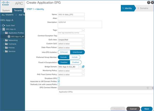
7. Click Next.
8. Click the [+] to the right of Associate VM Domain Profiles. For the Domain Profile, select VMware/HXV1-vDS from the drop-down list. Change the Deployment Immediacy and Resolution Immediacy to Immediate.
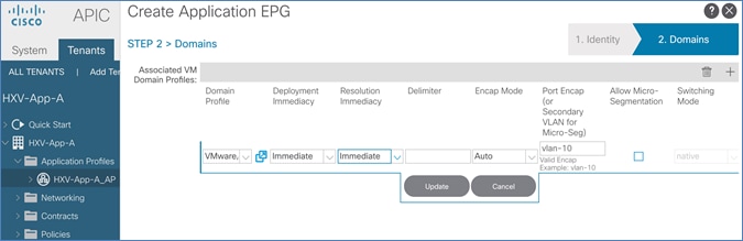
9. Click Update and then click Finish to complete the configuration.
10. In the left navigation pane, navigate to tenant HXV-App-A > Networking > Bridge Domains > HXV-App-A-Ext_BD. Right-click and select Create Subnet.
11. In the Create Subnet pop-up window, for the Gateway IP, enter IP address and mask (for example, 172.19.201.254/24). Select checkboxes for Advertised Externally and Shared between the VRFs.
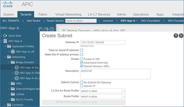
12. Click Submit.
EPG for App
To create EPG for App tier, follow these steps:
1. Use a browser to navigate to APIC’s Web GUI. Login with the admin account.
2. From the top menu, select Tenants > HXV-App-A. If you do not see this tenant in the top navigation menu, select Tenants > ALL TENANTS and double-click on HXV-App-A.
3. In the left navigation pane, navigate to Tenant HXV-App-A > Application Profiles > HXV-App-A_AP.
4. Right-click and select Create Application EPG.
5. In the Create Application EPG pop-up window, specify a Name for the EPG (HXV-A-App_EPG). Leave Intra EPG Isolation as Unenforced. For the Bridge Domain, select HXV-App-A-Int_BD from the drop-down list. Check the box next to Associate to VM Domain Profiles.
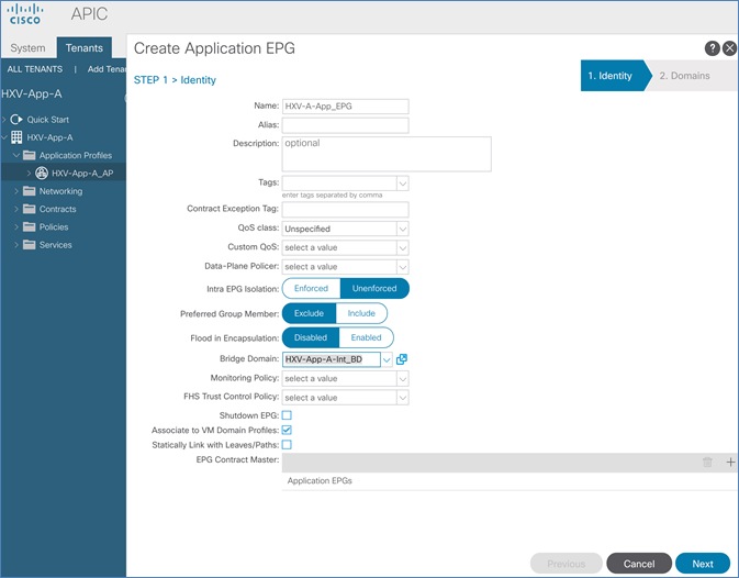
6. Click Next.
7. In STEP 2 > Domains window, click [+] to the right of Associate VM Domain Profiles. For the Domain Profile, select VMware/HXV1-vDS from the drop-down list. Change the Deployment Immediacy and Resolution Immediacy to Immediate.
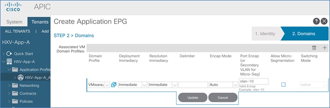
8. Click Update and then click Finish to complete the configuration.
9. In the left navigation pane, navigate to tenant HXV-App-A > Networking > Bridge Domains > HXV-App-A-Int_BD. Right-click and select Create Subnet.
10. In the Create Subnet pop-up window, for the Gateway IP, enter IP address and mask (for example, 172.19.202.254/24). Select checkboxes for Advertised Externally and Shared between the VRFs.

11. Click Submit.
Verify Virtual Networking for the Application EPGs
When the Application EPGs are provisioned in the ACI fabric and associated with a VMM domain, you should see corresponding port-groups on the VMware vDS switch in VMware vCenter. Now application virtual machines can be deployed and add to one of the port-groups for connectivity across the ACI Multi-Pod fabric. To verify that the port-groups have been created in the VMM domain (VMware vCenter), follow these steps:
1. Use a browser to navigate to the VMware vCenter server managing the HyperFlex Application cluster. Click the vSphere Web Client of your choice. Log in using an Administrator account
2. Navigate to the Home screen, select Networking in the Inventories section.
3. In the left navigation pane, expand the datacenter folder and distributed virtual switch created by the Cisco APIC.
4. In the right windowpane, navigate to Configure > Topology. The port-groups associated with the two EPGs should’ve been automatically created by APIC’s integration with VMware vCenter.
5. The application virtual machines can now be deployed and added to these port-groups. However, for connectivity outside the EPG, the necessary contracts need to be provided and consumed between the different EPGs as outlined in the next section.
Configure Contracts
App-Tier to Web-Tier Contract
To enable communication between Web and App tiers of the application, follow these steps:
![]() You can use more restrictive contracts to replace the Allow-Shared-L3Out contract defined in this example.
You can use more restrictive contracts to replace the Allow-Shared-L3Out contract defined in this example.
Provided Contract in EPG App-A
To add a Provided Contract in EPG App-A, follow these steps:
1. Use a browser to navigate to APIC’s Web GUI. Login with the admin account.
2. From the top menu, select Tenants > HXV-App-A. If you do not see this tenant in the top navigation menu, select Tenants > ALL TENANTS and double-click on HXV-App-A.
3. From the left navigation pane, expand and select Tenant HXV-App-A > Application Profiles > HXV-App-A_AP > Application EPGs > HXV-A-App_EPG.
4. Right-click HXV-A-App_EPG and select Add Provided Contract.
5. In the Add Provided Contract pop-up window, for Contract, select Create Contract from end of the drop-down list.
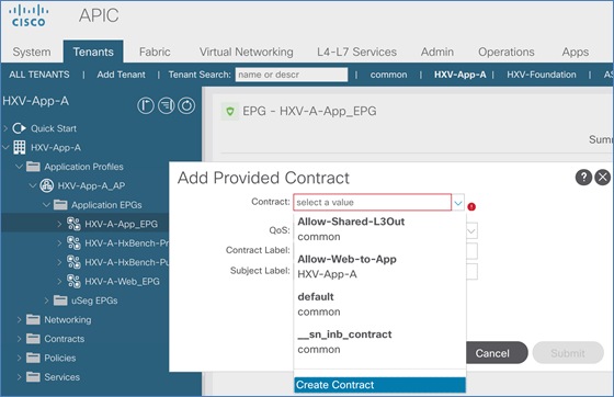
6. In the Create Contract pop-up window, for Name, specify a name for the contract (Allow-Web-to-App). For Scope, select Tenant from the drop-down list.
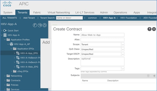
7. For Subjects, click [+] to add a Contract Subject.
8. In the Create Contract Subject pop-up window, specify a Name (Allow-Web-to-App_Subj) for the subject. For Filters, click [+] on the right side of the window to add a Contract filter.
9. For the Name, click on the drop-down list and click [+] to add a new filter.
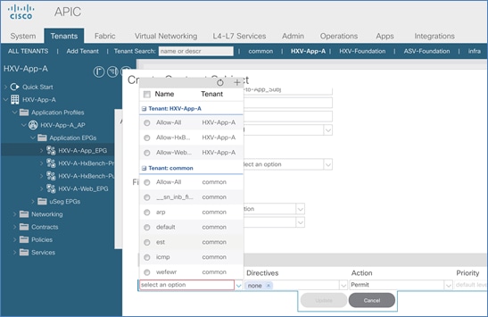
10. In the Create Filter pop-up window, specify a Name for the filter: Allow-Web-A-All. For Entries, click [+] on the right side of the window to add an Entry. Enter a Name for the Entry, for example: Allow-All. For the EtherType, select IP from the drop-down list.
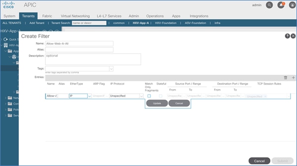
11. Click Update and Submit to finish creating the filter and close the Create Filter pop-up window.
12. Click Update in the Create Contract Subject pop-up window and OK to finish creating the Contract Subject and close the Create Contract Subject pop-up window.
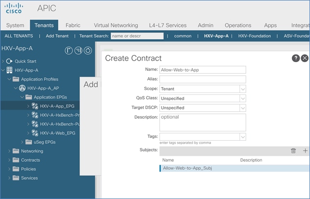
13. Click Submit to complete creating the Contract and close the Create Contract pop-up window.
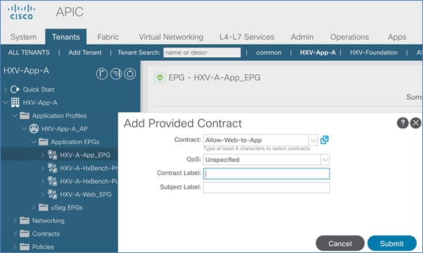
14. Click Submit to complete adding the Provided Contract and close the Add Provided Contract pop-up window.
Consume Contract in EPG Web-A
To consume a Contract in EPG Web-A, follow these steps:
1. Use a browser to navigate to APIC’s Web GUI. Login using the admin account.
2. From the top menu, select Tenants > HXV-App-A. If you do not see this tenant in the top navigation menu, select Tenants > ALL TENANTS and double-click on HXV-App-A.
3. In the left navigation pane, expand and select Tenant HXV-App-A > Application Profiles > HXV-App-A_AP > Application EPGs > HXV-A-Web_EPG. Right-click and select Add Consumed Contract.
4. In the Add Consumed Contract pop-up window, select the newly created contract (Allow-Web-to-App) from the drop-down list.
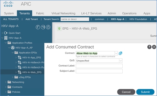
5. Click Submit to complete adding the Consumed Contract.
Web-Tier to Shared L3Out Contract
To enable App-A’s Web VMs to communicate outside the Fabric, Shared L3 Out contract defined in the Common Tenant will be consumed by the Web EPG. To enable Web virtual machines to outside the fabric, follow these steps:
1. Use a browser to navigate to APIC’s Web GUI. Login using the admin account.
2. From the top menu, select Tenants > HXV-App-A. If you do not see this tenant in the top navigation menu, select Tenants > ALL TENANTS and double-click on HXV-App-A.
3. In the left navigation pane, expand and select Tenant HXV-App-A > Application Profiles > HXV-App-A_AP > Application EPGs > HXV-A-Web_EPG. Right-click and select Add Consumed Contract.
4. In the Add Consumed Contract pop-up window, select the shared L3Out contract (common/Allow-Shared-L3Out).
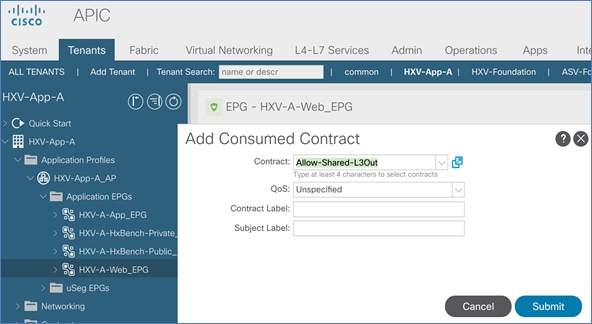
5. Click Submit to complete adding the Consumed Contract.
This section provides a high-level summary of the validation done for this CVD.
Validated Hardware and Software
Table 77 lists the hardware and software versions used to validate the solution in Cisco labs. The versions are consistent with versions recommended in the interoperability matrixes supported by Cisco and VMware.
Table 77 Hardware and Software Versions
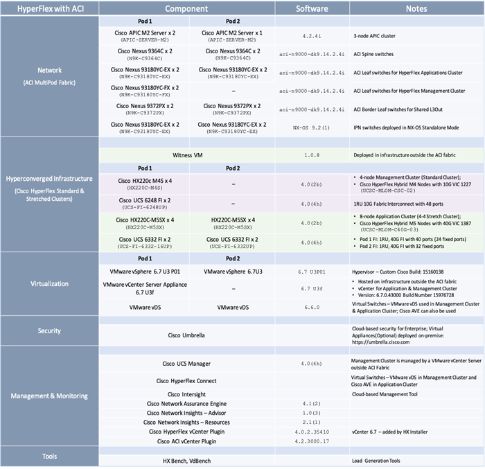
Interoperability
To use hardware models or software versions that was different from the ones , verify interoperability using the following matrixes. Also, review the release notes for release and product documentation.
· Cisco UCS and HyperFlex Hardware and Software Interoperability Tool
· Cisco ACI Recommended Release
· Cisco ACI Virtualization Compatibility Matrix
· Cisco APIC and ACI Virtual Edge Support Matrix
Solution Validation
The solution was validated for basic data forwarding by deploying virtual machine running VdBench and IOMeter tools. The system was validated for resiliency by failing various aspects of the system under load. Examples of the types of tests executed include:
· Failure and recovery of various links and components between the sites and within each site.
· Failure events triggering vSphere high availability between sites.
· Failure events triggering vMotion between sites.
· All tests were performed under load, using load generation tools. Different IO profiles representative of customer deployments were used.
The Cisco HyperFlex Stretched Cluster with Cisco ACI Multi-Pod Fabric solution for VMware vSphere deployments delivers an active-active data center solution that can span different geographical locations to provide disaster avoidance in Enterprise data centers. In the event of a site failure, Cisco HyperFlex stretched cluster can enable business continuity with no data loss. To interconnect the data centers, Cisco HyperFlex offers is integrated with Cisco ACI Multi-Pod fabric to provide seamless Layer 2 extension and workload mobility between sites. Cisco ACI also offers a software-defined, application-centric, policy-based network architecture that enable applications to be deployed in a simple and secure manner. The ACI Multi-Pod fabric is also centrally and uniformly managed using a single APIC cluster that simplifies the operation of a multi data center solution. The hyperconverged infrastructure is also centrally managed from the cloud using Cisco Intersight.
Cisco HyperFlex
· Comprehensive Documentation for Cisco HyperFlex: http://hyperflex.io
· Comprehensive Documentation Roadmap for Cisco HyperFlex: https://www.cisco.com/c/en/us/td/docs/hyperconverged_systems/HyperFlex_HX_DataPlatformSoftware/HX_Documentation_Roadmap/HX_Series_Doc_Roadmap.html
· Pre-installation Checklist for Cisco HX Data Platform: https://www.cisco.com/c/en/us/td/docs/hyperconverged_systems/HyperFlex_HX_DataPlatformSoftware/HyperFlex_Preinstall_Checklist/b_HX_Data_Platform_Preinstall_Checklist.html
· HyperFlex Hardening Guide: https://www.cisco.com/c/dam/en/us/support/docs/hyperconverged-infrastructure/hyperflex-hx-data-platform/HX-Hardening_Guide_v3_5_v12.pdf
· HyperFlex Installation Guide for Cisco Intersight: https://www.cisco.com/c/en/us/td/docs/hyperconverged_systems/HyperFlex_HX_DataPlatformSoftware/HyperFlex_Installation_Guide_for_Intersight/b_HyperFlex_Installation_Guide_for_Intersight/b_HyperFlex_Installation_Guide_for_Intersight_chapter_011.html
· Operating Cisco HyperFlex HX Data Platform Stretched Clusters:
https://www.cisco.com/c/dam/en/us/products/collateral/hyperconverged-infrastructure/hyperflex-hx-series/operating-hyperflex.pdf
· Cisco HyperFlex Systems Stretched Cluster Guide, Release 3.5:
https://www.cisco.com/c/en/us/td/docs/hyperconverged_systems/HyperFlex_HX_DataPlatformSoftware/HyperFlex_Stretched_Cluster/3_5/b_HyperFlex_Systems_Stretched_Cluster_Guide_3_5.html
Cisco UCS
· Cisco Unified Computing System:
http://www.cisco.com/en/US/products/ps10265/index.html
· Cisco UCS 6300 Series Fabric Interconnects:
http://www.cisco.com/c/en/us/products/servers-unified-computing/ucs-6300-series-fabric-interconnects/index.html
· Cisco UCS 5100 Series Blade Server Chassis:
http://www.cisco.com/en/US/products/ps10279/index.html
· Cisco UCS 2300 Series Fabric Extenders:
https://www.cisco.com/c/en/us/products/collateral/servers-unified-computing/ucs-6300-series-fabric-interconnects/datasheet-c78-675243.html
· Cisco UCS 2200 Series Fabric Extenders:
https://www.cisco.com/c/en/us/products/collateral/servers-unified-computing/ucs-6300-series-fabric-interconnects/data_sheet_c78-675243.html
· Cisco UCS B-Series Blade Servers:
http://www.cisco.com/en/US/partner/products/ps10280/index.html
· Cisco UCS C-Series Rack Mount Servers:
http://www.cisco.com/c/en/us/products/servers-unified-computing/ucs-c-series-rack-servers/index.html
· Cisco UCS VIC Adapters:
http://www.cisco.com/en/US/products/ps10277/prod_module_series_home.html
· Cisco UCS Manager:
http://www.cisco.com/en/US/products/ps10281/index.html
· Cisco UCS Manager Plug-in for VMware vSphere Web Client:
http://www.cisco.com/c/en/us/td/docs/unified_computing/ucs/sw/vmware_tools/vCenter/vCenter_Plugin_Release_Notes/2_0/b_vCenter_RN_for_2x.html
Cisco ACI Application Centric Infrastructure (ACI)
· Cisco ACI Infrastructure Best Practices Guide:
https://www.cisco.com/c/en/us/td/docs/switches/datacenter/aci/apic/sw/1-x/ACI_Best_Practices/b_ACI_Best_Practices.html
· Cisco ACI Infrastructure Release 2.3 Design Guide:
https://www.cisco.com/c/en/us/solutions/collateral/data-center-virtualization/application-centric-infrastructure/white-paper-c11-737909.pdf
· Cisco ACI Multi-Pod Configuration Whitepaper: https://www.cisco.com/c/en/us/solutions/collateral/data-center-virtualization/application-centric-infrastructure/white-paper-c11-739714.html
· Cisco ACI Multi-Pod White Paper:
https://www.cisco.com/c/en/us/solutions/collateral/data-center-virtualization/application-centric-infrastructure/white-paper-c11-737855.html
· Cisco APIC Layer Network Configuration Guide, Release 4.0(1): https://www.cisco.com/c/en/us/td/docs/switches/datacenter/aci/apic/sw/4-x/L3-configuration/Cisco-APIC-Layer-3-Networking-Configuration-Guide-401/Cisco-APIC-Layer-3-Networking-Configuration-Guide-401_chapter_010110.html#id_30270
· ACI Switch Command Reference, NX-OS Release 13.X: https://www.cisco.com/c/en/us/td/docs/switches/datacenter/aci/apic/sw/3-x/cli/inxos/13x/b_ACI_Switch_Command_Ref_13x.html
Cisco AVE
· Cisco ACI Virtual Edge White paper:
https://www.cisco.com/c/dam/en/us/solutions/collateral/data-center-virtualization/application-centric-infrastructure/white-paper-c11-740131.pdf
· Cisco APIC and ACI Virtual Edge Support Matrix:
https://www.cisco.com/c/dam/en/us/td/docs/Website/datacenter/aveavsmatrix/index.html
Security
· Integrating Cisco Umbrella to Cisco HyperFlex and Cisco UCS Solutions:
https://www.cisco.com/c/dam/en/us/products/collateral/hyperconverged-infrastructure/hyperflex-hx-series/whitepaper-c11-741088.pdf
Interoperability Matrixes
· Cisco UCS and HyperFlex Hardware Compatibility Matrix: https://ucshcltool.cloudapps.cisco.com/public/
· VMware and Cisco Unified Computing System:
http://www.vmware.com/resources/compatibility
· Cisco ACI Virtualization Compatibility Matrix: https://www.cisco.com/c/dam/en/us/td/docs/Website/datacenter/aci/virtualization/matrix/virtmatrix.html
· Cisco APIC and ACI Virtual Edge Support Matrix: https://www.cisco.com/c/dam/en/us/td/docs/Website/datacenter/aveavsmatrix/index.html
Archana Sharma, Technical Leader, Cisco UCS Data Center Solutions, Cisco Systems Inc.
Archana Sharma is Technical Marketing Engineer with over 20 years of experience at Cisco on a range of technologies that span Data Center, Desktop Virtualization, Collaboration, and other Layer2 and Layer3 technologies. Archana is focused on systems and solutions for Enterprise and Provider deployments, including delivery of Cisco Validated designs for 10 years. Archana is currently working on designing and integrating Cisco UCS-based Converged Infrastructure solutions. Archana holds a CCIE (#3080) in Routing and Switching and a Bachelor’s degree in Electrical Engineering from North Carolina State University.
Acknowledgements
For their support and contribution to the design, validation, and creation of this Cisco Validated Design, the author would like to thank:
· Haseeb Niazi, Technical Marketing Engineer, Cisco Systems, Inc.