FlexPod Datacenter with Cisco UCS 4.2(1) in UCS Managed Mode, VMware vSphere 7.0 U2, and NetApp ONTAP 9.9 Design Guide
Available Languages
Bias-Free Language
The documentation set for this product strives to use bias-free language. For the purposes of this documentation set, bias-free is defined as language that does not imply discrimination based on age, disability, gender, racial identity, ethnic identity, sexual orientation, socioeconomic status, and intersectionality. Exceptions may be present in the documentation due to language that is hardcoded in the user interfaces of the product software, language used based on RFP documentation, or language that is used by a referenced third-party product. Learn more about how Cisco is using Inclusive Language.
- US/Canada 800-553-2447
- Worldwide Support Phone Numbers
- All Tools
 Feedback
 Feedback

FlexPod Datacenter with Cisco UCS 4.2(1) in UCS Managed Mode, VMware vSphere 7.0 U2, and NetApp ONTAP 9.9 Design Guide
Published: October 2021

In partnership with:

About the Cisco Validated Design Program
The Cisco Validated Design (CVD) program consists of systems and solutions designed, tested, and documented to facilitate faster, more reliable, and more predictable customer deployments. For more information, go to:
http://www.cisco.com/go/designzone.
ALL DESIGNS, SPECIFICATIONS, STATEMENTS, INFORMATION, AND RECOMMENDATIONS (COLLECTIVELY, "DESIGNS") IN THIS MANUAL ARE PRESENTED "AS IS," WITH ALL FAULTS. CISCO AND ITS SUPPLIERS DISCLAIM ALL WARRANTIES, INCLUDING, WITHOUT LIMITATION, THE WARRANTY OF MERCHANTABILITY, FITNESS FOR A PARTICULAR PURPOSE AND NONINFRINGEMENT OR ARISING FROM A COURSE OF DEALING, USAGE, OR TRADE PRACTICE. IN NO EVENT SHALL CISCO OR ITS SUPPLIERS BE LIABLE FOR ANY INDIRECT, SPECIAL, CONSEQUENTIAL, OR INCIDENTAL DAMAGES, INCLUDING, WITHOUT LIMITATION, LOST PROFITS OR LOSS OR DAMAGE TO DATA ARISING OUT OF THE USE OR INABILITY TO USE THE DESIGNS, EVEN IF CISCO OR ITS SUPPLIERS HAVE BEEN ADVISED OF THE POSSIBILITY OF SUCH DAMAGES.
THE DESIGNS ARE SUBJECT TO CHANGE WITHOUT NOTICE. USERS ARE SOLELY RESPONSIBLE FOR THEIR APPLICATION OF THE DESIGNS. THE DESIGNS DO NOT CONSTITUTE THE TECHNICAL OR OTHER PROFESSIONAL ADVICE OF CISCO, ITS SUPPLIERS OR PARTNERS. USERS SHOULD CONSULT THEIR OWN TECHNICAL ADVISORS BEFORE IMPLEMENTING THE DESIGNS. RESULTS MAY VARY DEPENDING ON FACTORS NOT TESTED BY CISCO.
CCDE, CCENT, Cisco Eos, Cisco Lumin, Cisco Nexus, Cisco StadiumVision, Cisco TelePresence, Cisco WebEx, the Cisco logo, DCE, and Welcome to the Human Network are trademarks; Changing the Way We Work, Live, Play, and Learn and Cisco Store are service marks; and Access Registrar, Aironet, AsyncOS, Bringing the Meeting To You, Catalyst, CCDA, CCDP, CCIE, CCIP, CCNA, CCNP, CCSP, CCVP, Cisco, the Cisco Certified Internetwork Expert logo, Cisco IOS, Cisco Press, Cisco Systems, Cisco Systems Capital, the Cisco Systems logo, Cisco Unified Computing System (Cisco UCS), Cisco UCS B-Series Blade Servers, Cisco UCS C-Series Rack Servers, Cisco UCS S-Series Storage Servers, Cisco UCS Manager, Cisco UCS Management Software, Cisco Unified Fabric, Cisco Application Centric Infrastructure, Cisco Nexus 9000 Series, Cisco Nexus 7000 Series. Cisco Prime Data Center Network Manager, Cisco NX-OS Software, Cisco MDS Series, Cisco Unity, Collaboration Without Limitation, EtherFast, EtherSwitch, Event Center, Fast Step, Follow Me Browsing, FormShare, GigaDrive, HomeLink, Internet Quotient, IOS, iPhone, iQuick Study, LightStream, Linksys, MediaTone, MeetingPlace, MeetingPlace Chime Sound, MGX, Networkers, Networking Academy, Network Registrar, PCNow, PIX, PowerPanels, ProConnect, ScriptShare, SenderBase, SMARTnet, Spectrum Expert, StackWise, The Fastest Way to Increase Your Internet Quotient, TransPath, WebEx, and the WebEx logo are registered trademarks of Cisco Systems, Inc. and/or its affiliates in the United States and certain other countries. (LDW_P2)
All other trademarks mentioned in this document or website are the property of their respective owners. The use of the word partner does not imply a partnership relationship between Cisco and any other company. (0809R)
© 2021 Cisco Systems, Inc. All rights reserved.
Contents
Cisco Validated Designs (CVDs) consist of systems and solutions that are designed, tested, and documented to facilitate and improve customer deployments. These designs incorporate a wide range of technologies and products into a portfolio of solutions that have been developed to address the business needs of our customers.
This document describes the Cisco and NetApp® FlexPod® solution, which is a validated approach for deploying Cisco and NetApp technologies as shared cloud infrastructure. This validated design provides a framework for deploying VMware vSphere, the most popular virtualization platform in enterprise class data centers, on FlexPod.
This solution is also being offered as Infrastructure as code via ansible playbooks. This helps eliminate the human errors in manual tasks, accelerates the deployment and delivers consistent and repeatable solution deployment with all the solution best practices.
FlexPod is a leading integrated infrastructure supporting a broad range of enterprise workloads and use cases. This solution enables customers to quickly and reliably deploy VMware vSphere based private cloud on integrated infrastructure.
The recommended solution architecture is built on Cisco Unified Computing System (Cisco UCS) using the unified software release to support the Cisco UCS hardware platforms including Cisco UCS B-Series blade and C-Series rack servers, Cisco UCS 6454 Fabric Interconnects, Cisco Nexus 9000 Series switches, Cisco MDS Fibre channel switches, and NetApp All Flash series storage arrays. In addition to that, it includes VMware vSphere 7.0 Update 2, which provides several new features for optimizing storage utilization and facilitating private cloud.
Cisco and NetApp® have carefully validated and verified the FlexPod solution architecture and its many use cases while creating a portfolio of detailed documentation, information, and references to assist customers in transforming their data centers to this shared infrastructure model. This portfolio includes, but is not limited to the following items:
● Best practice architectural design
● Workload sizing and scaling guidance
● Implementation and deployment instructions
● Technical specifications (rules for what is a FlexPod® configuration)
● Frequently asked questions and answers (FAQs)
● Cisco Validated Designs (CVDs) and NetApp Validated Architectures (NVAs) describing a variety of use cases
Cisco and NetApp have also built a robust and experienced support team focused on FlexPod solutions, from customer account and technical sales representatives to professional services and technical support engineers. The support alliance between NetApp and Cisco gives customers and channel services partners direct access to technical experts who collaborate with cross vendors and have access to shared lab resources to resolve potential issues.
FlexPod supports tight integration with virtualized and cloud infrastructures, making it the logical choice for long-term investment. FlexPod also provides a uniform approach to IT architecture, offering a well-characterized and documented shared pool of resources for application workloads. FlexPod delivers operational efficiency and consistency with the versatility to meet a variety of SLAs and IT initiatives, including:
● Application rollouts or application migrations
● Business continuity and disaster recovery
● Desktop virtualization
● Cloud delivery models (public, private, hybrid) and service models (IaaS, PaaS, SaaS)
● Asset consolidation and virtualization
Industry trends indicate a vast data center transformation toward shared infrastructure and cloud computing. Business agility requires application agility, so IT teams need to provision applications quickly and resources need to be able to scale up (or down) in minutes.
FlexPod Datacenter is a best practice datacenter architecture, designed and validated by Cisco and NetApp to meet the needs of enterprise customers and service providers. FlexPod Datacenter is built on NetApp All Flash FAS (AFF), Cisco Unified Computing System (Cisco UCS), Cisco MDS, and the Cisco Nexus family of switches. These components combine to enable management synergies across all business IT infrastructure. FlexPod Datacenter has been proven to be the optimal platform for virtualization and workload consolidation, enabling enterprises to standardize all their IT infrastructure.
The audience for this document includes, but is not limited to; sales engineers, field consultants, professional services, IT managers, partner engineers, and customers who want to take advantage of an infrastructure built to deliver IT efficiency and enable IT innovation.
The primary FlexPod Datacenter with VMware vSphere 7.0 U2 validated design introduced new hardware and software into the portfolio, enabling use of 3rd generation Intel scalable processors and 3rd generation AMD EPYC processors.
In this release, all the components in the FlexPod Infrastructure are deployed in an optional automated approach using Ansible. The end-to-end Day 0 automation includes support for NetApp ONTAP Storage, Cisco UCS Compute, Cisco Nexus switches, Cisco MDS Switches, VMware vSphere and NetApp Management tools. The manual configuration of all components is also included in the Deployment Guide
This primary design has been updated to include the latest Cisco and NetApp hardware and software, along with the following:
● Support for the Cisco UCS 4.2(1) unified software release, Cisco UCS B200-M6 and C220-M6 servers with 3rd Generation Intel Xeon Scalable Processors and Cisco UCS C225-M6 servers with AMD EPYC 3rd Generation Processors, all with Cisco 1400 Series Virtual Interface Cards (VICs)
● Support for 200 Series Intel Optane Persistent Memory in Memory Mode with specific memory configurations and App Direct Mode
● Configuration of the Cisco Nexus switches, NetApp storage, Cisco UCS, Cisco MDS switches, VMware ESXi and vCenter, NetApp ONTAP Tools, and NetApp AIQUM with Ansible playbooks
● Cisco UCS Best Practice Recommended Virtualization BIOS Policies for Intel-based M6, Intel-based M5, and AMD-based C125 servers
● Support for NVMe over Fibre Channel (FC-NVMe) VMware datastores
● Support for NFS 4.1 VMware datastores
● Support for NetApp FlexGroup datastores (NFS 3 and 4.1)
● Support for Cisco Intersight Integration with NetApp storage for storage inventory, monitoring, and orchestration
● Support Cisco Intersight Cloud Orchestrator (ICO), providing orchestration of NetApp storage, Cisco UCS servers, and VMware vCenter and ESXi
● Support for the Cisco UCS Manager Plugin for VMware vCenter 3.0.5
● Support for the latest release of NetApp ONTAP® 9.9.1
● Support for NetApp ONTAP Tools for VMware vSphere 9.8
● Support for NetApp SnapCenter and NetApp SnapCenter Plug-in for VMware vSphere Version 4.5
● Support for NetApp Active IQ Unified Manager 9.9P1
● Support for Cisco Nexus NX-OS System Software 9.3(8)
● Support for Cisco MDS NX-OS System Software 8.4(2c)
● Support for Cisco Data Center Network Manager (DCNM)-SAN Version 11.5(1)
FlexPod is a best practice datacenter architecture that includes the following components:
● Cisco Unified Computing System
● Cisco Nexus switches
● Cisco MDS switches
● NetApp AFF systems
Figure 1. FlexPod Component Families
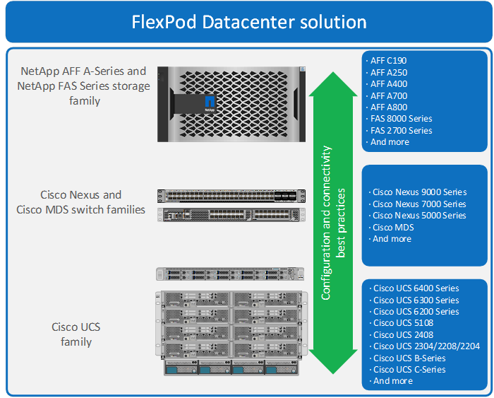
These components are connected and configured according to the best practices of both Cisco and NetApp to provide an ideal platform for running a variety of enterprise workloads with confidence. FlexPod can scale up for greater performance and capacity (adding compute, network, or storage resources individually as needed), or it can scale out for environments that require multiple consistent deployments (such as rolling out of additional FlexPod stacks). The reference architecture covered in this document leverages Cisco Nexus 9000 for the network switching element and pulls in the Cisco MDS 9000 for the SAN switching component.
One of the key benefits of FlexPod is its ability to maintain consistency during scale. Each of the component families shown (Cisco UCS, Cisco Nexus, and NetApp AFF) offers platform and resource options to scale the infrastructure up or down, while supporting the same features and functionality that are required under the configuration and connectivity best practices of FlexPod.
Infrastructure as Code with Ansible
This FlexPod solution delivers a fully automated solution deployment that covers all sections of the infrastructure and application layer. The configuration of the NetApp Storage, Cisco Network and Compute and VMware layers are automated by leveraging Ansible playbooks that have been designed to setup the components as per the solution best practices that were identified during the testing and validation. This automation capability augments the standard manual deployment procedures that are provided in the deployment guide.
The deployment guide provides a well-defined sequence of execution across the different constituents of this solution. Certain phases of the deployment also involve the exchange of parameters or attributes between compute, network, storage, and virtualization and may also involve some manual intervention. All phases have been clearly demarcated and the implementation with automation is split into equivalent phases via Ansible playbooks with a ‘tag’ based execution of a specific section of the component’s configuration.
Figure 2. Infrastructure Overview
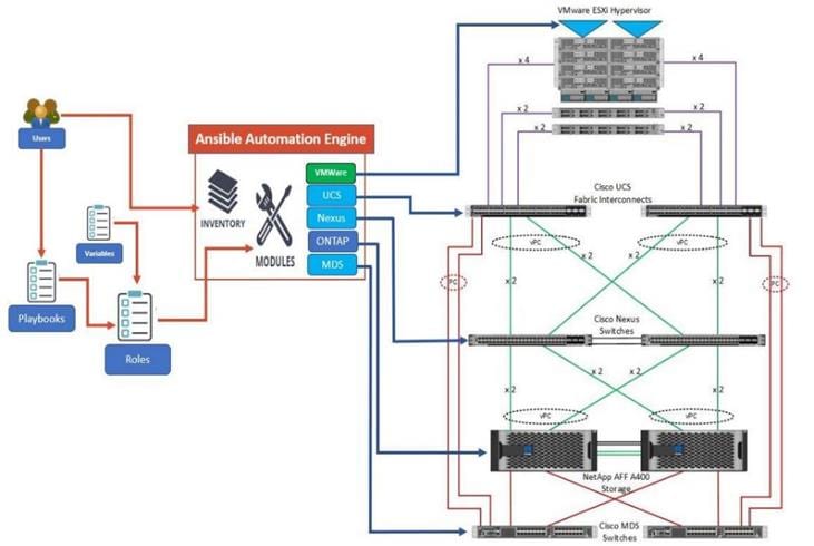
As illustrated in Figure 2, the Ansible playbooks to configure the different sections of the solution invoke a set of Roles and consume the associated variables that are required to setup the solution. The variables needed for this solution can be split into two categories – user input and defaults/ best practices. Based on the installation environment customers can choose to modify the variables to suit their requirements and proceed with the automated installation.
The automation for ONTAP is scalable in nature that can configure anywhere from a single HA pair to a fully scaled 24 node ONTAP cluster.
After the base infrastructure is setup with NetApp ONTAP, Cisco Network and Compute and VMware, customers can also deploy ONTAP tools for VMware formerly Virtual Storage Console and AIQUM in an automated fashion.
Another key benefit of this automation package is that customers can reuse parts of the code/roles to execute repeatable tasks using the tags that are associated with the fine-grained tasks within the roles.
Cisco Unified Computing System
Cisco UCS B200 M6 Blade Servers
The Cisco UCS B200 M6 server shown in Figure 3, is a half-width blade upgrade from the Cisco UCS B200 M5.
Figure 3. Cisco UCS B200 M6 Blade Server
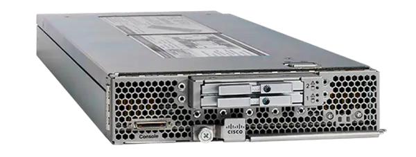
It features:
● 3rd Gen Intel® Xeon® Scalable processors with up to 40 cores per socket, 2-socket
● Up to 80 Gbps of I/O throughput with Cisco UCS 6454 FI
● Two optional, hot-pluggable, Solid-State Drives (SSDs), or Non-Volatile Memory Express (NVMe) 2.5-inch drives with a choice of enterprise-class Redundant Array of Independent Disks (RAIDs) or pass-through controllers or 4 M.2 SATA drives for flexible boot and local storage capabilities
For more information about the Cisco UCS B200 M6 Blade Servers, see: https://www.cisco.com/c/en/us/products/collateral/servers-unified-computing/ucs-b-series-blade-servers/datasheet-c78-2368888.html.
Cisco UCS C220 M6 Rack Servers
The Cisco UCS C220 M6 rack server shown in Figure 4, is a high-density 2-socket rack server that is an upgrade from the Cisco UCS C220 M5.
Figure 4. Cisco UCS C220 M6 Rack Server
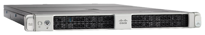
It features:
● 3rd Gen Intel® Xeon® Scalable processors with up to 40 cores per socket, 2-socket
● Up to 32 DDR4 DIMMs for improved performance with up to 16 DIMM slots ready for Intel Optane™ DC Persistent Memory
● Up to 3 PCIe 4.0 slots plus a modular LAN on Motherboard (mLOM) slot
● Up to 10 SAS/SATA or NVMe disk drives
● Up to two GPUs supported
● Up to 100 Gbps of I/O throughput with Cisco UCS 6454 FI
For more information about the Cisco UCS C220 M6 Rack Servers, see: https://www.cisco.com/c/en/us/products/collateral/servers-unified-computing/ucs-c-series-rack-servers/at-a-glance-c45-2375918.html?wcmmode=disabled.
![]() The Cisco UCS C220 M6 Rack Server is currently supported in FlexPod but has not yet been validated.
The Cisco UCS C220 M6 Rack Server is currently supported in FlexPod but has not yet been validated.
Cisco UCS C225 M6 Rack Servers
The Cisco UCS C225 M6 rack server shown in Figure 5, is a high-density 2-socket rack server utilizing AMD EPYC CPUs that is single-socket optimized.
Figure 5. Cisco UCS C225 M6 Rack Server
It features
● 3rd Gen AMD EPYC series processors, with up to 64 cores per socket
● 32 DIMM slots (16 DIMMs per CPU socket), 3200 MHZ DDR4 for up to 8TB of capacity
● Up to 10 Small-Form-Factor (SFF) front-loading hot-pluggable drives – NVMe/SAS/SATA
● Up to three PCIe 4.0 slots
● Internal dual M.2 drive options
● Support for Cisco’s fourth-generation PCIe Virtual Interface Card (VIC) 1467 offering up to 100 Gbps of I/O throughput with Cisco UCS 6454 FI
For more information about the Cisco UCS C225 M6 Rack Servers, see: https://www.cisco.com/c/en/us/products/collateral/servers-unified-computing/ucs-c-series-rack-servers/nb-06-ucs-c225-m6-rack-serv-aag-cte-en.html.
![]() The Cisco UCS C225 M6 Rack Server is currently supported in FlexPod but has not yet been validated.
The Cisco UCS C225 M6 Rack Server is currently supported in FlexPod but has not yet been validated.
Intel Optane DC Persistent Memory in Cisco UCS B200 M6 and Cisco UCS C220 M6 Servers
Intel 200 Series Optane DC Persistent Memory was validated in Cisco UCS B200 M6 servers in two ways. The first validation was running a VMware ESXi 7.0U2 Host in VMware supported Memory Mode as specified in vSphere Support for Intel's Optane Persistent Memory (PMEM) (67645). In this validation, the 2-socket server platform with 2TB available memory was setup with the Balanced Profile BIOS setting and no issues were seen with the ESXi host. The second validations were in App Direct Mode. The first validation in App Direct Mode was to configure Intel Optane in App Direct Mode, not use it, and show that it had no effect on running applications. Testing was also done in assigning NVDIMMs to Windows Server 2016 VMs and using them as direct access (DAX) fast disks. Intel 200 Series Optane memory is 3200MHz along with the standard DIMMs.
Cisco UCS 6400 Series Fabric Interconnects
The Cisco UCS Fabric Interconnects provide a single point for connectivity and management for the entire Cisco Unified Computing System. Typically deployed as an active-active pair, the system’s fabric interconnects integrate all components into a single, highly available management domain controlled by Cisco UCS Manager. The fabric interconnects manage all I/O efficiently and securely at a single point, resulting in deterministic I/O latency regardless of a server or virtual machine’s topological location in the system.
The Cisco UCS Fabric Interconnect provides both network connectivity and management capabilities for Cisco Unified Computing System. IOM modules in the blade chassis support power supply, along with fan and blade management. They also support port channeling and, thus, better use of bandwidth. The IOMs support virtualization-aware networking in conjunction with the Fabric Interconnects and Cisco Virtual Interface Cards (VIC).
The Cisco UCS 6400 Series Fabric Interconnect is a core part of Cisco Unified Computing System, providing both network connectivity and management capabilities for the system. The Cisco UCS 6400 Series offers line-rate, low-latency, lossless 10/25/40/100 Gigabit Ethernet, Fibre Channel over Ethernet (FCoE), and 32 Gigabit Fibre Channel functions.
The Cisco UCS 6454 54-Port Fabric Interconnect is a One-Rack-Unit (1RU) 10/25/40/100 Gigabit Ethernet, FCoE and Fibre Channel switch offering up to 3.82 Tbps throughput and up to 54 ports. The switch has 28 10/25-Gbps Ethernet ports, 4 1/10/25-Gbps Ethernet ports, 6 40/100-Gbps Ethernet uplink ports and 16 unified ports that can support 10/25-Gbps Ethernet ports or 8/16/32-Gbps Fibre Channel ports. All Ethernet ports are capable of supporting FCoE.
The Cisco UCS 64108 Fabric Interconnect (FI) is a 2-RU top-of-rack switch that mounts in a standard 19-inch rack such as the Cisco R Series rack. The 64108 is a 10/25/40/100 Gigabit Ethernet, FCoE and Fiber Channel switch offering up to 7.42 Tbps throughput and up to 108 ports. The switch has 16 unified ports (port numbers 1-16) that can support 10/25-Gbps SFP28 Ethernet ports or 8/16/32-Gbps Fibre Channel ports, 72 10/25-Gbps Ethernet SFP28 ports (port numbers 17-88), 8 1/10/25-Gbps Ethernet SFP28 ports (port numbers 89-96), and 12 40/100-Gbps Ethernet QSFP28 uplink ports (port numbers 97-108). All Ethernet ports are capable of supporting FCoE. The Cisco UCS 64108 FI is supported in the FlexPod solution but was not validated in this project.
For more information on the Cisco UCS 6400 Series Fabric Interconnects, see the Cisco UCS 6400 Series Fabric Interconnects Data Sheet.
Cisco UCS 2408 Fabric Extender
The Cisco UCS 2408 connects the I/O fabric between the Cisco UCS 6454 Fabric Interconnect and the Cisco UCS 5100 Series Blade Server Chassis, enabling a lossless and deterministic converged fabric to connect all blades and chassis together. Because the fabric extender is similar to a distributed line card, it does not perform any switching and is managed as an extension of the fabric interconnects. This approach removes switching from the chassis, reducing overall infrastructure complexity, and enabling Cisco UCS to scale to many chassis without multiplying the number of switches needed, reducing TCO, and allowing all chassis to be managed as a single, highly available management domain.
The Cisco UCS 2408 Fabric Extender has eight 25-Gigabit Ethernet, FCoE-capable, Small Form-Factor Pluggable (SFP28) ports that connect the blade chassis to the fabric interconnect. Each Cisco UCS 2408 provides 10-Gigabit Ethernet ports connected through the midplane to each half-width slot in the chassis, giving it a total 32 10G interfaces to UCS blades. Typically configured in pairs for redundancy, two fabric extenders provide up to 400 Gbps of I/O from FI 6400's to 5108 chassis.
Cisco UCS 1400 Series Virtual Interface Cards (VICs)
Cisco VICs support Cisco SingleConnect technology, which provides an easy, intelligent, and efficient way to connect and manage computing in your data center. Cisco SingleConnect unifies LAN, SAN, and systems management into one simplified link for rack servers and blade servers. This technology reduces the number of network adapters, cables, and switches needed and radically simplifies the network, reducing complexity. Cisco VICs can support 256 Express (PCIe) virtual devices, either virtual Network Interface Cards (vNICs) or virtual Host Bus Adapters (vHBAs), with a high rate of I/O Operations Per Second (IOPS), support for lossless Ethernet, and 10/25/40/100-Gbps connection to servers. The PCIe Generation 3 x16 interface helps ensure optimal bandwidth to the host for network-intensive applications, with a redundant path to the fabric interconnect. Cisco VICs support NIC teaming with fabric failover for increased reliability and availability. In addition, it provides a policy-based, stateless, agile server infrastructure for your data center.
The Cisco VIC 1400 series can be used in both the M6 and M5 generations of Cisco UCS B-Series Blade Servers and Cisco UCS C-Series Rack Servers. The adapters are capable of supporting 10/25/40/100-Gigabit Ethernet and Fibre Channel over Ethernet (FCoE). It incorporates Cisco’s next-generation Converged Network Adapter (CNA) technology and offers a comprehensive feature set, providing investment protection for future feature software releases.
Cisco Unified Computing System is revolutionizing the way servers are managed in the datacenter. The following are the unique differentiators of Cisco Unified Computing System and Cisco UCS Manager.
● Embedded Management — In Cisco UCS, the servers are managed by the embedded firmware in the Fabric Interconnects, eliminating need for any external physical or virtual devices to manage the servers.
● Unified Fabric — In Cisco UCS, from blade server chassis or rack servers to FI, there is a single Ethernet cable used for LAN, SAN, and management traffic. This converged I/O results in reduced cables, SFPs and adapters – reducing capital and operational expenses of the overall solution.
● Auto Discovery — By simply inserting the blade server in the chassis or connecting the rack server to the fabric interconnect, discovery and inventory of compute resources occurs automatically without any management intervention. The combination of unified fabric and auto-discovery enables the wire-once architecture of Cisco UCS, where compute capability of Cisco UCS can be extended easily while keeping the existing external connectivity to LAN, SAN, and management networks.
● Policy Based Resource Classification — Once a compute resource is discovered by Cisco UCS Manager, it can be automatically classified to a given resource pool based on policies defined. This capability is useful in multi-tenant cloud computing. This CVD showcases the policy-based resource classification of Cisco UCS Manager.
● Combined Rack and Blade Server Management — Cisco UCS Manager can manage Cisco UCS B-series blade servers and Cisco UCS C-series rack servers under the same Cisco UCS domain. This feature, along with stateless computing makes compute resources truly hardware form factor agnostic.
● Model based Management Architecture — The Cisco UCS Manager architecture and management database is model based, and data driven. An open XML API is provided to operate on the management model. This enables easy and scalable integration of Cisco UCS Manager with other management systems.
● Policies, Pools, Templates — The management approach in Cisco UCS Manager is based on defining policies, pools, and templates, instead of cluttered configuration, which enables a simple, loosely coupled, data driven approach in managing compute, network, and storage resources.
● Loose Referential Integrity — In Cisco UCS Manager, a service profile, port profile or policies can refer to other policies or logical resources with loose referential integrity. A referred policy cannot exist at the time of authoring the referring policy or a referred policy can be deleted even though other policies are referring to it. This provides different subject matter experts to work independently from each-other. This provides great flexibility where different experts from different domains, such as network, storage, security, server, and virtualization work together to accomplish a complex task.
● Policy Resolution — In Cisco UCS Manager, a tree structure of organizational unit hierarchy can be created that mimics the real-life tenants and/or organization relationships. Various policies, pools and templates can be defined at different levels of organization hierarchy. A policy referring to another policy by name is resolved in the organizational hierarchy with closest policy match. If no policy with specific name is found in the hierarchy of the root organization, then the special policy named “default” is searched. This policy resolution practice enables automation friendly management APIs and provides great flexibility to owners of different organizations.
● Service Profiles and Stateless Computing — A service profile is a logical representation of a server, carrying its various identities and policies. This logical server can be assigned to any physical compute resource as far as it meets the resource requirements. Stateless computing enables procurement of a server within minutes, which used to take days in legacy server management systems.
● Built-in Multi-Tenancy Support — The combination of policies, pools and templates, loose referential integrity, policy resolution in the organizational hierarchy and a service profiles-based approach to compute resources makes Cisco UCS Manager inherently friendly to multi-tenant environments typically observed in private and public clouds.
● Extended Memory — The enterprise-class Cisco UCS B200 M5 blade server extends the capabilities of Cisco’s Unified Computing System portfolio in a half-width blade form factor. The Cisco UCS B200 M5 harnesses the power of the latest Intel® Xeon® Scalable Series processor family CPUs with up to 3 TB of RAM (using 128 GB DIMMs) – allowing huge VM to physical server ratios required in many deployments or allowing large memory operations required by certain architectures like big data.
● Simplified QoS — Even though Fibre Channel and Ethernet are converged in the Cisco UCS fabric, built-in support for QoS and lossless Ethernet makes it seamless. Network Quality of Service (QoS) is simplified in Cisco UCS Manager by representing all system classes in one GUI panel.
NetApp AFF A-Series Storage
With the new NetApp® AFF A-Series controller lineup, NetApp provides industry leading performance while continuing to provide a full suite of enterprise-grade data management and data protection features. AFF A-Series systems support end-to-end NVMe technologies, from NVMe-attached SSDs to front-end NVMe over Fibre Channel (NVMe/FC) host connectivity. These systems deliver the industry’s lowest latency for an enterprise all-flash array, making them a superior choice for driving the most demanding workloads and artificial intelligence (AI) and deep learning (DL) applications. With a simple software upgrade to the modern NVMe/FC SAN infrastructure, you can drive more workloads with faster response times, without disruption or data migration. Additionally, more and more organizations are adopting a “cloud first” strategy, driving the need for enterprise-grade data services for a shared environment across on-premises data centers and the cloud. As a result, modern all-flash arrays must provide robust data services, integrated data protection, seamless scalability, and new levels of performance— plus deep application and cloud integration. These new workloads demand performance that first generation flash systems cannot deliver.
For more information about the NetApp AFF A-series controllers, see the AFF product page: https://www.netapp.com/us/products/storage-systems/all-flash-array/aff-a-series.aspx.
You can view or download more technical specifications of the AFF A-series controllers here: https://www.netapp.com/us/media/ds-3582.pdf
The NetApp AFF A400 offers full end-to-end NVMe support. The front-end NVMe/FC connectivity makes it possible to achieve optimal performance from an all-flash array for workloads that include artificial intelligence, machine learning, real-time analytics as well as business-critical databases. On the back end, the A400 supports both serial-attached SCSI (SAS) and NVMe-attached SSDs, offering the versatility for current customers to move up from their legacy A-Series systems and satisfying the increasing interest that all customers have in NVMe-based storage. Furthermore, this system was built to provide expandability options, so you won’t have to make a costly leap from a midrange to a high-end system to increase scalability. Consider this a way to future-proof your NetApp investment.
The A400 offers greater port availability, network connectivity, and expandability. The NetApp AFF A400 has 10 PCIe Gen3 slots per high availability pair. The NetApp AFF A400 offers 25GbE or 100GbE, as well as 32Gb/FC and NVMe/FC network connectivity. This model was created to keep up with changing business needs and performance and workload requirements by merging the latest technology for data acceleration and ultra-low latency in an end-to-end NVMe storage system.
Figure 6. Figure 6 NetApp AFF A400
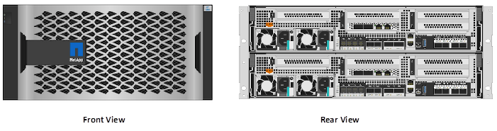
The NetApp AFF A400 has a 4U enclosure with two possible onboard connectivity configurations (25GbE or 32Gb/FC). In addition, the A400 is the only A-Series system that has the new smart I/O card with offload engine. The offload engine is computational and independent from the CPU, which allows better allocation of processing power. This system also offers an improved level of serviceability over the previous NetApp 4U chassis: The fan cooling modules have been moved from inside the controller to the front of the chassis, so cabling does not have to be disconnected and reconnected when replacing an internal fan.
The NetApp AFF A400 is well suited for enterprise applications that require the best balance of performance and cost, as well as very demanding workloads that require ultra-low latency. The smart I/O card serves as the default cluster interconnect, making the system an ideal solution for highly compressible workloads.
NetApp ONTAP® 9.9.1 is the data management software that is used with the NetApp AFF A400 all-flash storage system in the solution design. ONTAP software offers secure unified storage for applications that read and write data over block or file-access protocol storage configurations. These storage configurations range from high-speed flash to lower-priced spinning media or cloud-based object storage.
ONTAP implementations can run on NetApp engineered FAS or AFF series arrays. They can run on commodity hardware (NetApp ONTAP Select), and in private, public, or hybrid clouds (NetApp Private Storage and NetApp Cloud Volumes ONTAP). Specialized implementations offer best-in-class converged infrastructure, featured here as part of the FlexPod® Datacenter solution or with access to third-party storage arrays (NetApp FlexArray® virtualization).
Together these implementations form the basic framework of the NetApp Data Fabric, with a common software-defined approach to data management, and fast efficient replication across systems. FlexPod and ONTAP architectures can serve as the foundation for both hybrid cloud and private cloud designs.
The following sections provide an overview of how ONTAP 9.9.1 is an industry-leading data management software architected on the principles of software defined storage.
Read more about all the capabilities of ONTAP data management software here: https://www.netapp.com/us/products/data-management-software/ontap.aspx
NetApp ONTAP offers support for the following features, all on the same platform:
● NAS protocols (NFS and SMB)
● SAN protocols (iSCSI, FCP, and NVMe)
● S3 data access
● Data protection (NetApp Snapshot copy, NetApp SnapMirror, and SnapVault technologies)
● Storage efficiencies (deduplication, compaction, and compression)
● High Availability (HA) failovers (including fast failovers for Tier-1 SAN with the All-SAN Array)
● Support for all-flash, spinning drive, and hybrid disk configurations
● Security features (multifactor authentication, NetApp Volume Encryption, and Secure Purge)
NetApp Storage Virtual Machine
A NetApp ONTAP cluster serves data through at least one, and possibly multiple, storage virtual machines (SVMs). An SVM is a logical abstraction that represents the set of physical resources of the cluster. Data volumes and network LIFs are created and assigned to an SVM and can reside on any node in the cluster to which that SVM has access. An SVM can own resources on multiple nodes concurrently, and those resources can be moved non-disruptively from one node in the storage cluster to another. For example, a NetApp FlexVol® flexible volume can be non-disruptively moved to a new node and aggregate, or a data LIF can be transparently reassigned to a different physical network port. The SVM abstracts the cluster hardware, and therefore it is not tied to any specific physical hardware.
An SVM can support multiple data protocols concurrently. Volumes within the SVM can be joined to form a single NAS namespace. The namespace makes all the SVM's data available through a single share or mount point to NFS and CIFS clients. SVMs also support block-based protocols, and LUNs can be created and exported by using iSCSI, FC, and FCoE. Any or all these data protocols can be used within a given SVM. Storage administrators and management roles can be associated with an SVM, offering higher security and access control. This security is important in environments that have more than one SVM and when the storage is configured to provide services to different groups or sets of workloads. In addition, you can configure external key management for a named SVM in the cluster. This is a best practice for multitenant environments in which each tenant uses a different SVM (or set of SVMs) to serve data.
Storage Efficiencies or Data Reduction
Storage efficiency or Data Reduction is a primary architectural design point of ONTAP data management software. A wide array of features enables you to store more data that uses less space. In addition to deduplication and compression, you can store your data more efficiently by using features such as unified storage, multitenancy, thin provisioning, and by using NetApp Snapshot™ technology.
Starting with ONTAP 9, NetApp guarantees that the use of NetApp storage efficiency technologies on AFF systems reduces the total logical capacity used to store customer data up to a data reduction ratio of 7:1, based on the workload. This space reduction is enabled by a combination of several different technologies, including deduplication, compression, and compaction.
Compaction, which was introduced in ONTAP 9, is the latest patented storage efficiency technology released by NetApp. In the NetApp WAFL® file system, all I/O takes up 4KB of space, even if it does not actually require 4KB of data. Compaction combines multiple blocks that are not using their full 4KB of space together into one block. This single block can be more efficiently stored on the disk to save space. These storage efficiencies improve the ability of ONTAP to store more data in less space, reducing storage costs and maximizing the effective capacity of your storage system.
FabricPool
FabricPool is a hybrid storage solution with ONTAP 9 that uses an all-flash (SSD) aggregate as a performance tier and an object store in a public cloud service as a cloud tier. This configuration enables policy-based data movement, depending on whether data is frequently accessed. FabricPool is supported in ONTAP for both AFF and all-SSD aggregates on FAS platforms. Data processing is performed at the block level, with frequently accessed data blocks in the all-flash performance tier tagged as hot and infrequently accessed blocks tagged as cold.
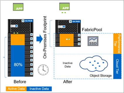
Using FabricPool helps to reduce storage costs without compromising performance, efficiency, security, or protection. FabricPool is transparent to enterprise applications and capitalizes on cloud efficiencies by lowering storage TCO without having to rearchitect the application infrastructure.
Encryption
Data security remains an important consideration for customers purchasing storage systems. Before ONTAP 9, NetApp supported full disk encryption in storage clusters. However, in ONTAP 9, the encryption capabilities of ONTAP are extended by adding an Onboard Key Manager (OKM). The OKM generates and stores keys for each of the drives in ONTAP, enabling ONTAP to provide all functionality required for encryption out of the box. Through this functionality, known as NetApp Storage Encryption (NSE), sensitive data stored on disk is secure and can only be accessed by ONTAP.
NetApp has extended the encryption capabilities further with NetApp Volume Encryption (NVE), a software-based mechanism for encrypting data. It allows a user to encrypt data at the volume level instead of requiring encryption of all data in the cluster, providing more flexibility and granularity to ONTAP administrators. This encryption extends to Snapshot copies and NetApp FlexClone volumes that are created in the cluster. One benefit of NVE is that it runs after the implementation of the storage efficiency features, and, therefore, it does not interfere with the ability of ONTAP to create space savings.
NVE unifies the data encryption capabilities available on-premises and extends them into the cloud. NVE is FIPS 140-2 compliant, this compliance helps businesses adhere to federal regulatory guidelines for data at rest in the cloud.
NetApp Volume Encryption and Secure Purge provided a way to mitigate potential disasters like data spill by offering a way to cryptographically shred individual files by deleting the security encryption key associated with the file. After that key is gone, that data is no longer recoverable from disk. This process has been externally validated by a data recovery company using NIST SP 800-88 guidelines for media sanitation.
For more information about encryption in ONTAP, see the NetApp Power Encryption Guide in the NetApp ONTAP 9 Documentation Center.
NVMe over Fibre Channel
NVMe is a new SAN protocol that helps improve latency and performance with block workloads over traditional FCP and iSCSI. NetApp introduced support for NVMe over Fibre Channel in ONTAP 9.4 and has been adding feature enhancements in each release.
ONTAP 9.8 adds the following:
● NVMe/FC on the same SVM with FCP and iSCSI. Now, you can use NVMe/FC on the same SVMs as your other SAN protocols, which simplifies management of your SAN environments.
● Gen 7 SAN switch fabric support. This feature adds support for the newer Gen-7 SAN switches.
In ONTAP 9.9.1:
● NVMe over Fibre Channel namespaces can now failover by way of an inactive remote path, providing greater overall resiliency for NVMe/FC applications.
● ONTAP 9.9.1 introduces support for NVMe/FC with VMware virtualization workloads by providing vVol support and provisioning of namespaces through vCenter.
S3 Protocol
Object storage with the S3 protocol is the newest addition to the ONTAP protocol family. Added as a public preview in ONTAP 9.7, S3 is now a fully supported protocol in ONTAP 9.8.
Support for S3 includes the following:
● Basic PUT/GET object access (does not include access to both S3 and NAS from the same bucket)
● No object tagging or ILM support; for feature-rich, globally dispersed S3, use NetApp StorageGRID.
● TLS 1.2 encryption
● Multi-part uploads
● Adjustable ports
● Multiple buckets per volume
● Bucket access policies
● S3 as a NetApp FabricPool target
For more details on S3 and ONTAP 9.9.1 refer to TR4814.
NAS Protocol Enhancements
Network Attached Storage (NAS) protocols refer to file-based transfer methods such as NFS and SMB/CIFS. The following enhancements were added to ONTAP 9.8 for NAS protocol support, as well as features that apply specifically to NAS, such as NetApp FlexGroup and FlexCache volumes.
ONTAP 9.8 offers the following NFS enhancements:
● NFSv4.2. Offers basic NFSv4.2 protocol support and does not include NFSv4.2 features such as labeling. NFSv4.2 is enabled when NFSv4.1 is enabled.
● Qtree Quality of Service (QoS). Provides a way for storage administrators to apply QoS maximums and minimums to qtrees in ONTAP. This is currently only available with REST APIs and the command line, does not include adaptive QoS support, and is NFS only.
FlexGroup
FlexGroup volumes are the NetApp ONTAP scale-out NAS solution, providing up to 20PB and 400 billion files in a single namespace, while offering automatically load-balanced parallel processing of high ingest workloads for a blend of capacity, performance, and simplicity.
In ONTAP 9.9.1, FlexGroup volumes support the following data protection configurations:
● Cascading and fan-out SnapMirror
● Storage virtual machine disaster recovery (SVM-DR)
● SnapLock enhancements
For more information about FlexGroup volumes, see TR-4571: NetApp FlexGroup Volumes Best Practices.
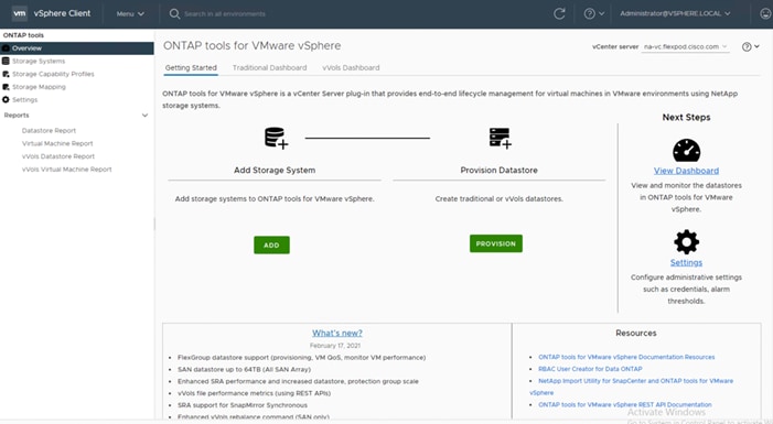
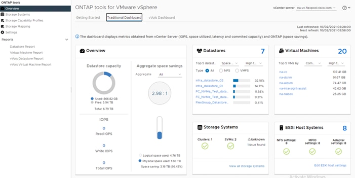
ONTAP Tools 9.8
The ONTAP tools for VMware vSphere provide end-to-end life cycle management for virtual machines in VMware environments that use NetApp storage systems. It simplifies storage and data management for VMware environments by enabling administrators to directly manage storage within the vCenter Server. Starting with the 9.8 release, the virtual appliance for VSC, VASA Provider, and SRA is renamed to ONTAP tools for VMware vSphere.
The 9.8 release of ONTAP tools provides the following:
● You can now provision FlexGroup datastores and set QoS policies for virtual machines in FlexGroup backed datastores. You can also monitor virtual machines performance provisioned on FlexGroup datastores. These capabilities are available in the vCenter UI and via REST API.
● Supports SAN datastores up to the maximum VMFS size of 64TB. Datastore sizes above 16TB are only supported on ASA (All SAN Array) platforms for datastores created using cluster admin level credentials and not supported with SVM credentials.
● Supports enhanced SRA performance and 500 protection groups per Recovery plan.
● Supports REST APIs for vVols file metrics.
● SRA supports synchronous SnapMirror operations
● Each component in ONTAP tools provides capabilities to help manage your storage more efficiently.
Virtual Storage Console (VSC)
VSC enables you to perform the following tasks:
● Add storage controllers, assign credentials, and set up permissions for storage controllers of VSC, that both SRA and VASA Provider can leverage
● Provision datastores
● Monitor the performance of the datastores and virtual machines in your vCenter Server environment
● Control administrator access to the vCenter Server objects by using role-based access control (RBAC) at two levels:
● vSphere objects, such as virtual machines and datastores
● ONTAP storage systems are managed by using ONTAP RBAC.
● View and update the host settings of the ESXi hosts that are connected to NetApp storage
VSC provisioning operations benefit from using the NFS Plug-in for VMware vStorage APIs for Array Integration (VAAI). The NFS Plug-in for VAAI is a software library that integrates the VMware Virtual Disk Libraries that are installed on the ESXi host. The VMware VAAI package enables the offloading of certain tasks from the physical hosts to the storage array. You can perform tasks such as thin provisioning and hardware acceleration at the array level to reduce the workload on the ESXi hosts. The copy offload feature and space reservation feature improve the performance of VSC operations.
VASA Provider
VASA Provider for ONTAP uses VMware vSphere APIs for Storage Awareness (VASA) to send information about storage used by VMware vSphere to the vCenter Server. ONTAP tools has VASA Provider integrated with VSC. VASA Provider enables you to perform the following tasks:
● Provision VMware Virtual Volumes (vVols) datastores
● Create and use storage capability profiles that define different storage service level objectives (SLOs) for your environment
● Verify for compliance between the datastores and the storage capability profiles
● Set alarms to warn you when volumes and aggregates are approaching the threshold limits
● Monitor the performance of virtual machine disks (VMDKs) and the virtual machines that are created on vVols datastores
Storage Replication Adapter (SRA)
When SRA is enabled and used in conjunction with VMware Site Recovery Manager (SRM), you can recover the vCenter Server datastores and virtual machines in the event of a failure. SRA enables you to use array based replication (ABR) for protected sites and recovery sites for disaster recovery in the event of a failure.
NetApp SnapCenter® is a NetApp next-generation data protection software for tier 1 enterprise applications. SnapCenter Software is a simple, centralized, scalable platform that provides application-consistent data protection for applications, databases, host file systems, and VMs running on ONTAP systems anywhere in the Hybrid Cloud.
SnapCenter leverages NetApp Snapshot, SnapRestore, FlexClone, SnapMirror, and SnapVault technologies to provide the following:
● Fast, space-efficient, application-consistent, disk-based backups
● Rapid, granular restore and application-consistent recovery
● Quick, space-efficient cloning
SnapCenter enables seamless integration with Oracle, Microsoft, SAP, MongoDB and VMware across FC, iSCSI, and NAS protocols. This integration enables IT organizations to scale their storage infrastructure, meet increasingly stringent SLA commitments, and improve the productivity of administrators across the enterprise.
The SnapCenter platform is based on a multitiered architecture that includes a centralized management server (SnapCenter Server) and a SnapCenter plug-in host.
Figure 7 illustrates the high-level architecture of the NetApp SnapCenter Server.
Figure 7. SnapCenter Architecture
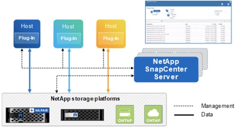
The SnapCenter Server includes a web server, a centralized HTML5-based user interface, PowerShell cmdlets, REST APIs, and the SnapCenter repository.
SnapCenter enables load balancing, high availability, and horizontal scaling across multiple SnapCenter Servers within a single user interface. You can accomplish high availability by using Network Load Balancing (NLB) and Application Request Routing (ARR) with SnapCenter. For larger environments with thousands of hosts, adding multiple SnapCenter Servers can help balance the load.
The SnapCenter Server can push out plug-ins to remote hosts. These plug-ins are used to interact with an application, a database, or a file system. The SnapCenter Server and plug-ins communicate with the host agent using HTTPS. Usually, the plug-ins must be present on the remote host so that application-level or database-level commands can be issued from the same host where the application or database is running.
To manage the plug-ins and the interaction between the SnapCenter Server and the plug-in host, SnapCenter uses SM Service. SM service is a NetApp SnapManager® web service running on top of Windows Server internet information services (IIS) on the SnapCenter Server. SM Service takes all client requests such as backup, restore, and clone.
The SnapCenter Server communicates those requests to SMCore, which is a service that runs co-located within the SnapCenter Server and remote servers. SMCore plays a significant role in coordinating with the SnapCenter plug-ins package for Windows.
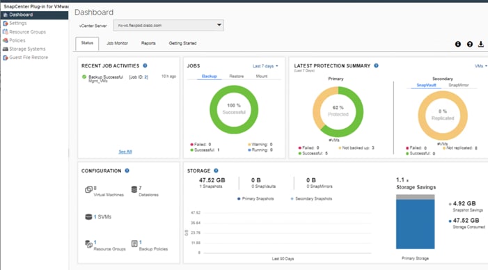
For SnapCenter 4.3 and later, the SnapCenter Plug-in for VMware vSphere is deployed as part the SnapCenter plugin for VMware vSphere virtual appliance. It provides a vSphere web client GUI on vCenter to protect virtual machines and datastores and supports SnapCenter application-specific plug-ins to protect virtualized databases on primary and secondary storage.
The SnapCenter Plug-in for VMware vSphere features provided by the virtual appliance include the following:
● Support for VMs, VMDKs, and datastores
◦ The plug-in provides a VMware vSphere web client in vCenter. You use the web client GUI to perform VM-consistent backups of VMs, VMDKs, and datastores. You can also restore VMs and VMDKs and restore files and folders that reside on a guest OS.
![]() When backing up VMs, VMDKs, and datastores, the SnapCenter plug-in for VMware vSphere does not support RDMs. Backup jobs for VMs ignore RDMs. If you need to backup RDMs, you must use a SnapCenter application-based plug-in.
When backing up VMs, VMDKs, and datastores, the SnapCenter plug-in for VMware vSphere does not support RDMs. Backup jobs for VMs ignore RDMs. If you need to backup RDMs, you must use a SnapCenter application-based plug-in.
◦ The plug-in also provides a MySQL database on the virtual appliance VM that contains SnapCenter Plug-in for VMware vSphere metadata.
● Support for virtualized databases
◦ The plug-in supports backup, recovery, and cloning of virtualized applications and file systems (for example, virtualized SQL, Oracle, and Exchange databases) when you have the appropriate application-based SnapCenter plug-ins installed, and you are using SnapCenter to perform data protection operations. Data protection operations are managed using the SnapCenter GUI. SnapCenter natively leverages the SnapCenter Plug-in for VMware vSphere for all data protection operations on VMDKs, raw device mappings (RDMs), and NFS datastores. After the virtual appliance is deployed, the plug- in handles all interactions with vCenter. The plug-in supports all SnapCenter application- based plug-ins.
● VMware Tools is required for VM consistent Snapshot copies
◦ If VMware Tools is not installed and running, the file system is not quiesced and a crash- consistent Snapshot is created.
● VMware Storage vMotion is required for restore operations in SAN (VMFS) environments
◦ The restore workflow for VMware file system (VMFS) utilizes the VMware Storage vMotion feature. Storage vMotion is a part of the vSphere Standard License but is not available with the vSphere Essentials or Essentials Plus licenses.
◦ Most restore operations in NFS environments use native ONTAP functionality (for example, Single File SnapRestore) and do not require VMware Storage vMotion.
● Backup jobs for VMs and datastores must be migrated to the SnapCenter Plug-in for VMware vSphere
SnapCenter Plug-in for VMware vSphere 4.5 New Features
The following are the new features:
● Secondary backup support for FlexGroups
● You can perform restore, guest file restore, mount and unmount, attach and detach operations on secondary backups for FlexGroups.
● Restore to alternate host
You can restore a VM to the following:
● An alternate ESXi host managed by the same vCenter
● An alternate ESXi host managed by a different vCenter in linked mode
● Large LUN support
You can protect datastores on large LUN sizes up to 128 TB on ASA aggregates. For large LUNs, SnapCenter uses only thick provisioned LUNs to avoid latency.
● Upgrade of MySQL server
Upgrading to SnapCenter Plug-in for VMware vSphere 4.5 automatically upgrades MySQL server from 8.0.16 to 8.0.23.
● RESTAPIs
The following are new REST APIs for SnapCenter Plug-in for VMware vSphere:
● Add Configuration
● Update Configuration
● Get Configuration by key
In addition to these major features, the SnapCenter Plug-in for VMware vSphere also provides support for iSCSI, Fibre Channel, FCoE, NFS v3.0, NFS v4.1 and VMFS 5.0 and 6.0.
For the latest information about supported versions, see the NetApp Interoperability Matrix Tool (IMT).
For more information about SnapCenter data protection and the SnapCenter Plug-in for VMware vSphere, refer to the following documentation:
● Data Protection Guide for SnapCenter in the SnapCenter Documentation Center.
● SnapCenter Plug-in for VMware vSphere, see the SnapCenter Plug-in for VMware vSphere 4.3 Deployment Guide.
Active IQ Unified Manager 9.9P1
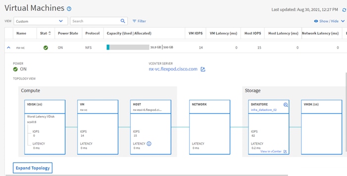
NetApp® Active IQ® Unified Manager is a comprehensive monitoring and proactive management tool for NetApp ONTAP® systems to help manage the availability, capacity, protection, and performance risks of your storage systems and virtual infrastructure. You can deploy Active IQ Unified Manager on a Linux server, on a Windows server, or as a virtual appliance on a VMware host.
Active IQ Unified Manager enables monitoring your ONTAP storage clusters, VMware vCenter server and virtual machines from a single redesigned, intuitive interface that delivers intelligence from community wisdom and AI analytics. It provides comprehensive operational, performance and proactive insights into the storage environment and the virtual machines running on it. When an issue occurs on the storage or virtual infrastructure, Active IQ Unified Manager can notify you about the details of the issue to help with identifying root cause. The virtual machine dashboard gives you a view into the performance statistics for the VM so that you can investigate the entire I/O path from the vSphere host down through the network and finally to the storage. Some events also provide remedial actions which can be taken to rectify the issue. You can configure custom alerts for events so that when issues occur, you are notified through email, and SNMP traps.
Active IQ Unified Manager enables management of storage objects in your environment by associating them with annotations. You can create custom annotations and dynamically associate clusters, storage virtual machines (SVMs), and volumes with the annotations through rules.
Active IQ Unified Manager also enables reporting different views of your network, providing actionable intelligence on capacity, health, performance, and data protection. You can customize your views by showing and hiding columns, rearranging columns, filtering data, sorting data, and searching the results. You can save custom views for reuse, download them as reports, and schedule them as recurring reports to distribute through email. Active IQ Unified Manager enables planning for the storage requirements of your users by forecasting capacity and usage trends to proactively act before issues arise preventing reactive short-term decisions which often lead additional problems in the long-term.
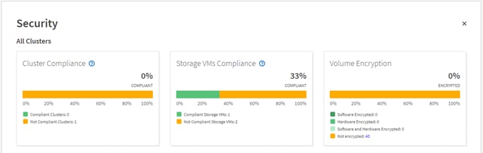
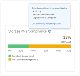
Active IQ Unified Manager uses rules based on the recommendations made in the Security Hardening Guide for NetApp ONTAP 9 (TR-4569) to evaluate the cluster and SVM configuration. Each recommendation is assigned a value and used to provide an overall compliance score for the ONTAP environment.
The compliance score is calculated by auditing certain recommendations made in the Security Hardening Guide and whether the remediation for those risks have been completed. The recommendations included are general in nature and can be applied to most ONTAP environments regardless of workload. Certain criteria are not counted against the compliance score because those configurations cannot be generally applied to all storage environments. Volume encryption would be one an example of this.
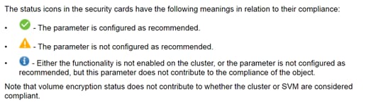
A list of recommendations being evaluated for compliance can be seen by selecting the blue question mark in each security card which also contains a link to the Security Hardening Guide for NetApp ONTAP 9.
For more information on Active IQ Unified Manager, refer to the Active IQ Unified Manager Documentation Resources page complete with a video overview and other product documentation.
NetApp Active IQ is a cloud service that provides proactive care and optimization of your NetApp environment, leading to reduced risk and higher availability. Active IQ leverages community wisdom and AIOps artificial intelligence to provide proactive recommendations and risk identification. The latest release of Active IQ offers an enhanced user interface and a personalized experience with Active IQ Digital Advisor dashboards. It allows smooth and seamless navigation, with its intuitiveness throughout different dashboards, widgets, and screens. It provides insights that help you detect and validate important relationships and meaningful differences based on the data that is presented by different dashboards.
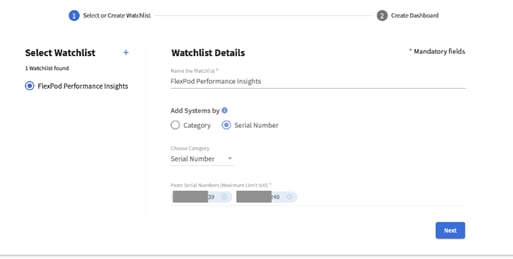
Watchlists are a way to organize a group of systems inside Active IQ Digital Advisor and create custom dashboards based on the system grouping. Watchlists provide quick access to only the group of storage systems you want, without having to sort or filter those you don’t.
The Wellness score on the dashboard provides a quick at-a-glance summary on the health of the installed systems based on the number of high risks and expired support contracts. Detailed information about the status of your storage system are sorted into the following six widgets:
● Performance and Efficiency
● Availability and Protection
● Capacity
● Configuration
● Security
● Renewals
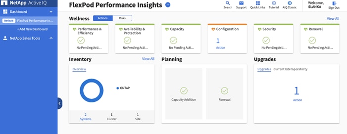
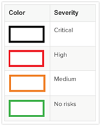
The intuitive interface allows you to switch between the Actions and Risks tab to view how the findings are broken down by category, or each unique risk. Color-coding the identified risks into four levels; Critical, High, Medium and No risks, further helps to quickly identify issues that need immediate attention.
Links to NetApp Bugs Online or NetApp MySupport knowledge base articles are incorporated in the corrective actions so that you can obtain further information about the issue and how to correct it before it becomes a problem in the environment.
Active IQ also integrates with the on-premises installation of Active IQ Unified Manager to correct certain issues identified in the Active IQ portal. These risks are identified with the green wrench symbol in the Risks tab inside Active IQ. Clicking the Fix It button will launch the installation of Active IQ Unified Manager 9.9P1 to proceed with correcting the issue. If no installation of Active IQ Unified Manager 9.9P1 exists, the option to install or upgrade an existing version of Active IQ Unified Manager will be presented for future risk mitigation.
The Cisco® MDS 9132T 32G Multilayer Fabric Switch is the next generation of the highly reliable, flexible, and low-cost Cisco MDS 9100 Series switches. It combines high performance with exceptional flexibility and cost effectiveness. This powerful, compact one rack-unit (1RU) switch scales from 8 to 32 line-rate 32 Gbps Fibre Channel ports. The Cisco MDS 9132T delivers advanced storage networking features and functions with ease of management and compatibility with the entire Cisco MDS 9000 Family portfolio for reliable end-to-end connectivity, including support of FC-NVMe. This switch also offers state-of-the-art SAN analytics and telemetry capabilities that have been built into this next-generation hardware platform for both SCSI (FC) and NVMe (FC-NVMe) based storage. This new state-of-the-art technology couples the next-generation port ASIC with a fully dedicated Network Processing Unit designed to complete analytics calculations in real time. The telemetry data extracted from the inspection of the frame headers are calculated on board (within the switch) and, using an industry-leading open format, can be streamed to any analytics-visualization platform. This switch also includes a dedicated 10/100/1000BASE-T telemetry port to maximize data delivery to any telemetry receiver including Cisco Data Center Network Manager.
For more information about the MDS 9132T, review the product data sheet: https://www.cisco.com/c/en/us/products/collateral/storage-networking/mds-9100-series-multilayer-fabric-switches/datasheet-c78-739613.html.
The MDS 9132T is inserted into the FlexPod design to provide 32 Gbps Fibre Channel switching between the NetApp AFF A400 storage controllers, and Cisco UCS Managed B-Series and C-Series servers connected to the Cisco UCS 6454 Fabric Interconnects. Adding the MDS to the FlexPod infrastructure allows for:
● Increased scaling of both the NetApp storage and the Cisco UCS compute resources
● Large range of existing models supported from the 9100, 9200, 9300, and 9700 product lines
● A dedicated network for fibre channel storage traffic
● Increased tenant separation
● Deployments utilizing existing qualified SAN switches that might be within the customer environment
Configuration of the Cisco MDS within this FlexPod design takes advantage of Smart Zoning to increase zoning and administration efficiency within the MDS. Smart Zoning allows for reduced TCAM (ternary content addressable memory) entries, which are fabric ACL entries of the MDS allowing traffic between targets and initiators. When calculating TCAMs used, two TCAM entries will be created for each connection of devices within the zone. Without Smart Zoning enabled for a zone, all targets will have a pair of TCAMs established between each other, and all initiators will additionally have a pair of TCAMs established to other initiators in the zone. In other words, all targets are zoned to all targets and all initiators are zoned to all initiators in addition to the desired all initiators being zoned to all targets.
Using Smart Zoning, Targets and Initiators are identified, reducing TCAMs needed to only target to initiator within the zone.
Within the traditional zoning model for a multiple initiator, multiple target zone, the TCAM entries will grow rapidly, representing a relationship of TCAMs = (T+I)*(T+I)-1) where T = targets and I = initiators. For Smart Zoning configuration, this same multiple initiator, multiple target zone will instead have TCAMs = 2*T*I where T = targets and I = initiators.
With Smart Zoning, zones can now be defined as one-to-many, many-to-one, or many-to-many without incurring a penalty in switch resource consumption. Thus, administrators can now define zones to correspond to entities that actually are meaningful in their data center operations. For example, they can define a zone for an application, or for an application cluster, or for a hypervisor cluster without compromising internal resource utilization. It is recommended in FlexPod to configure zones corresponding to NetApp Storage Virtual Machines (SVMs). In this configuration, the one zone for each SVM contains the Fibre Channel Logical Interface (LIF) targets for that fabric defined in the SVM, and the initiator worldwide node names (WWNNs) for that fabric for all Cisco UCS servers that need to access the SVM storage. Later, if any servers are added, the initiator WWNNs can then simply be added to the appropriate zones. This saves significant administrative effort over defining a separate zone for each UCS server and adding the redundant targets used by other UCS servers.
For more information about Smart Zoning, see: https://www.cisco.com/c/dam/en/us/products/collateral/storage-networking/mds-9100-series-multilayer-fabric-switches/at_a_glance_c45-708533.pdf.
Cisco Nexus series switches provide an Ethernet switching fabric for communications between the Cisco UCS, NetApp storage controllers, and the rest of a customer’s network. There are many factors to consider when choosing the main data switch in this type of architecture to support both the scale and the protocols required for the resulting applications. All Cisco Nexus switch models including the Cisco Nexus 5000 and Cisco Nexus 7000 are supported in this design and may provide additional features such as FCoE or OTV. However, be aware that there may be slight differences in setup and configuration based on the switch used. The validation for this deployment leverages the Cisco Nexus 9000 series switches, which deliver high performance 10/25/40/50/100GbE ports, density, low latency, and exceptional power efficiency in a broad range of compact form factors.
Many of the most recent single-site FlexPod designs also use this switch due to the advanced feature set and the ability to support Application Centric Infrastructure (ACI) mode. When leveraging ACI fabric mode, the Nexus 9000 series switches are deployed in a spine-leaf architecture. Although the reference architecture covered in this design does not leverage ACI, it lays the foundation for customer migration to ACI in the future, and fully supports ACI today if required.
For more information, refer to http://www.cisco.com/c/en/us/products/switches/nexus-9000-series-switches/index.html.
This FlexPod design deploys a single pair of Cisco Nexus 93180YC-FX top-of-rack switches within each placement, using the traditional standalone mode running NX-OS.
The traditional deployment model delivers numerous benefits for this design:
● High performance and scalability with L2 and L3 support per port
● Layer 2 multipathing with all paths forwarding through the Virtual port-channel (vPC) technology
● VXLAN support at line rate
● Advanced reboot capabilities include hot and cold patching
● Hot-swappable power-supply units (PSUs) and fans with N+1 redundancy
Cisco Nexus 9000 provides an Ethernet switching fabric for communications between the Cisco UCS domain, the NetApp storage system and the enterprise network. In the FlexPod design, Cisco UCS Fabric Interconnects and NetApp storage systems are connected to the Cisco Nexus 9000 switches using virtual Port Channels (vPC)
A virtual Port Channel (vPC) allows links that are physically connected to two different Cisco Nexus 9000 Series devices to appear as a single Port Channel. In a switching environment, the vPC provides the following benefits:
● Allows a single device to use a Port Channel across two upstream devices
● Eliminates Spanning Tree Protocol blocked ports and uses all available uplink bandwidth
● Provides a loop-free topology
● Provides fast convergence if either one of the physical links or a device fails
● Helps ensure high availability of the overall FlexPod system
Figure 8. Cisco Nexus 9000 Connections
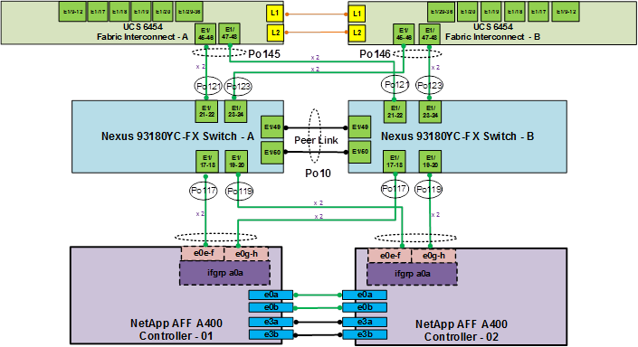
Figure 8 illustrates the connections between the Cisco Nexus 9000s, Cisco UCS Fabric Interconnects, and NetApp AFF A400s. A vPC requires a “peer link” which is documented as port channel 10 in this diagram. In addition to the vPC peer-link, the vPC peer keepalive link is a required component of a vPC configuration. The peer keepalive link allows each vPC enabled switch to monitor the health of its peer. This link accelerates convergence and reduces the occurrence of split-brain scenarios. In this validated solution, the vPC peer keepalive link uses the out-of-band management network. This link is not shown in Figure 8.
Cisco Nexus 9000 Best Practices
Cisco Nexus 9000 related best practices used in the validation of the FlexPod architecture are summarized below:
Cisco Nexus 9000 Features Enabled
● Link Aggregation Control Protocol (LACP part of 802.3ad)
● Cisco Virtual Port Channeling (vPC) for link and device resiliency
● Cisco Discovery Protocol (CDP) for infrastructure visibility and troubleshooting
● Link Layer Discovery Protocol (LLDP) for additional infrastructure visibility and troubleshooting
● Port channel type Port Profiles for consistent provisioning across port channel instances
vPC Considerations
● Define a unique domain ID
● Set the priority of the intended vPC primary switch lower than the secondary (default priority is 32768)
● Establish peer keepalive connectivity. It is recommended to use the out-of-band management network (mgmt0) or a dedicated switched virtual interface (SVI)
● Enable vPC auto-recovery feature
● Enable peer-gateway. Peer-gateway allows a vPC switch to act as the active gateway for packets that are addressed to the router MAC address of the vPC peer allowing vPC peers to forward traffic
● Enable IP ARP synchronization to optimize convergence across the vPC peer link.
● A minimum of two 10 Gigabit Ethernet connections are required for vPC
● All port channels should be configured in LACP active mode
Spanning Tree Considerations
● The spanning tree priority was not modified. Peer-switch (part of vPC configuration) is enabled which allows both switches to act as root for the VLANs
● Loopguard is disabled by default
● BPDU guard and filtering are enabled by default
● Bridge assurance is only enabled on the vPC Peer Link
● Ports facing the NetApp storage controller and UCS are defined as “edge” trunk ports
Cisco Nexus 93180YC-FX SAN Switching
Beginning with Cisco NX-OS Release 9.3(3), the Cisco Nexus 93180YC-FX switch supports SAN Switching, allowing a single switch to provide both SAN and LAN switching. Beginning with Cisco NX-OS Release 9.3(5) and continuing with Cisco NX-OS Release 9.3(8), validated in this design, the needed SAN switching features enhanced device alias and smart zoning are supported. These features allow Cisco Data Center Network Manager to both monitor the Cisco Nexus 93180YC-FX and to configure device aliases, zones, and zonesets. These features also allow a Cisco Nexus 93180YC-FX to be connected to an MDS switch or fabric and for device aliases and smart zones to be distributed between all switches in the fabric. Cisco Nexus 93180YC-FX SAN switching is covered in the appendix of the Deployment Guide for this solution. For more information on Cisco Nexus 93180YC-FX SAN Switching, please refer to https://www.cisco.com/c/en/us/td/docs/switches/datacenter/nexus9000/sw/93x/san_switching/configuration/guide/b-cisco-nexus-9000-nx-os-san-switching-configuration-guide-933.html.
For configuration details, refer to the Cisco Nexus 9000 Series Switches Configuration guides: http://www.cisco.com/c/en/us/support/switches/nexus-9000-series-switches/products-installation-and-configuration-guides-list.html.
Cisco Data Center Network Manager (DCNM)-SAN
Cisco DCNM-SAN can be used to monitor, configure, and analyze Cisco 32Gbps fibre channel fabrics and show information about the Cisco Nexus and Cisco UCS Ethernet switching fabric. Cisco DCNM-SAN is deployed as a virtual appliance from an OVA and is managed through a web browser. Once the Cisco MDS and Nexus switches and Cisco UCS fabric interconnects are added with the appropriate credentials and licensing, monitoring of the SAN and Ethernet fabrics can begin. Additionally, VSANs, Device Aliases, Zones, and Zonesets can be added, modified, and deleted using the DCNM point and click interface. Device Manager can also be used to configure the Cisco MDS switches. SAN Analytics can be added to Cisco MDS switches to provide insights into your fabric by allowing you to monitor, analyze, identify, and troubleshoot performance issues for both SCSI (FC) and NVMe (FC-NVME) based storage.
Cisco Intersight is a Software-as-a-Service (SaaS) infrastructure management platform that is augmented by other intelligent systems. It provides global management of the Cisco Unified Computing System™ (Cisco UCS) infrastructure anywhere. Intersight provides a holistic approach to managing distributed computing environments from the core to the edge. The Cisco Intersight virtual appliance (available in the Essentials edition) provides customers with deployment options while still offering all the benefits of SaaS. This deployment flexibility enables organizations to achieve a higher level of automation, simplicity, and operational efficiency.
Cisco UCS systems are fully programmable infrastructures. Cisco Intersight includes a RESTful API to provide full programmability and deep integrations with third-party tools and systems. The platform and the connected systems are DevOps-enabled to facilitate continuous delivery. Customers have come to appreciate the many benefits of SaaS infrastructure management solutions. Cisco Intersight monitors the health and relationships of all the physical and virtual infrastructure components. Telemetry and configuration information is collected and stored in accordance with Cisco’s information security requirements. The data is isolated and displayed through an intuitive user interface. The virtual appliance feature enables users to specify what data is sent back to Cisco with a single point of egress from the customer network.
This cloud-powered intelligence can assist organizations of all sizes. Because the Cisco Intersight software gathers data from the connected systems, it learns from hundreds of thousands of devices in diverse customer environments. This data is combined with Cisco best-practices to enable Cisco Intersight to evolve and become smarter. As the Cisco Intersight knowledge base increases, trends are revealed, and information and insights are provided through the recommendation engine.
In addition to Cisco UCS server status and inventory, Cisco Intersight Essentials provides the Cisco UCS server Hardware Compatibility List (HCL) check for Cisco UCS server drivers. In this FlexPod validation, the HCL check can be used to verify that the correct Cisco UCS VIC nfnic and nenic drivers are installed.
Cisco Intersight Integration with NetApp ONTAP Storage
Using NetApp Active IQ Unified Manager (AIQUM) and Cisco Intersight Assist, NetApp ONTAP storage controllers can now be shown in Cisco Intersight with general and inventory information. NetApp AQIUM is an OVA based VMware virtual machine that can monitor multiple NetApp ONTAP storage clusters and also provides an API gateway to those storage clusters where the individual storage cluster credentials are managed by AIQUM, and all authentications can be handled with just AIQUM’s credentials. When AIQUM is claimed by Cisco Intersight through the Intersight Assist appliance, all NetApp ONTAP storage clusters configured in AIQUM are pulled into Intersight. If you have installed the Intersight Advantage or Premier license, you can view this general and target inventory information, such as nodes, storage virtual machines, aggregates, disks, volumes, LUNs, initiator groups, network ports and network interfaces. With Premier License you can also execute NetApp ONTAP Storage tasks as workflows. The Virtualization and NetApp Storage tasks can be combined and executed as a single workflow.
Cisco Intersight Cloud Orchestrator (ICO)
Intersight Cloud Orchestrator is a framework to create and execute complex workflows in Cisco Intersight. A central workflow engine sequences the steps in workflows and automates the execution of workflows. A workflow could be made up of a couple of tasks or could include dozens of them and could also include sub workflows. The Cisco Intersight UI has a workflow designer to visualize a workflow definition and monitor the execution of a workflow.
A workflow is a collection of tasks that are orchestrated to perform certain operations. A workflow is created within an Intersight organization by giving it a name and version. Workflows are uniquely identified by name and version within an organization. When multiple versions of workflows are created, one of them can be marked as the default version. An Intersight Cloud Orchestrator (ICO) task is a building block of the workflow, and it can perform a simple operation or a sequence of operations including create, update, and delete operations on any target supported by Cisco Intersight. Each IO task is configured by providing the necessary inputs and after a successful execution of the task, the output may be passed onto another task as a required input.
Cisco Intersight provides a library of tasks that you can use to compile a workflow. Each task acts as an independent executable entity and you can use a task in multiple workflows. A task may perform an operation in Cisco Intersight, or it may use the Device Connector at the targets to carry out operations on external devices. A task uses the provided inputs, performs the operation, and produces outputs that can be passed to another task in the workflow. A task typically comprises these elements: Name, Label, Description, Inputs, and Outputs. The task labels and descriptions convey the intent and usage of the tasks. In addition to a library of supported tasks, Intersight Cloud Orchestrator provides a list of sample workflows that you can use to build your workflows.
Within FlexPod, if the Intersight Premier license is installed, ICO can be used to create workflows utilizing tasks to orchestrate Cisco UCS servers, VMware, and NetApp ONTAP storage. Workflows can be exported and imported from Intersight. Some sample workflows are built in the CVD Deployment Guide. The TR-4883 provides more information on the workflows and NetApp ONTAP storage tasks.
VMware vSphere 7.0 Update 2
VMware vSphere is a virtualization platform for holistically managing large collections of infrastructure (resources-CPUs, storage, and networking) as a seamless, versatile, and dynamic operating environment. Unlike traditional operating systems that manage an individual machine, VMware vSphere aggregates the infrastructure of an entire data center to create a single powerhouse with resources that can be allocated quickly and dynamically to any application in need.
vSphere 7.0 Update 2 brings a number of improvements and simplifications including, but not limited to:
● Support for FC-NVMe datastores with NetApp ONTAP storage
● Support for mounting NetApp NFS 4.1 datastores
● Support for mounting NetApp FlexGroup volumes as NFS 3 and 4.1 datastores
● vMotion is now tuned according to speed of the underlying physical network interfaces, taking advantage of 25, 40, and 100 Gbps interfaces, which are present in FlexPod.
For more information about VMware vSphere and its components, see: http://www.vmware.com/products/vsphere.html.
Figure 9 shows the VMware vSphere built on FlexPod components and the network connections for a configuration with the Cisco UCS 6454 Fabric Interconnects and 25 Gb Ethernet core networking. This design was validated and has port-channeled 25 Gb Ethernet connections between the Cisco UCS 5108 Blade Chassis and the Cisco UCS Fabric Interconnects, port-channeled 25 Gb Ethernet connections between the Cisco UCS C-Series rack-mounted servers and the Cisco UCS Fabric Interconnects, and 25 Gb Ethernet connections between the Cisco UCS Fabric Interconnect and Cisco Nexus 9000s, and between Cisco Nexus 9000s and NetApp AFF A400 storage array. The 25 Gb Ethernet connections in the topology can be scaled up or down to meet the bandwidth requirements of the solution.
Figure 9. FlexPod Validated Topology
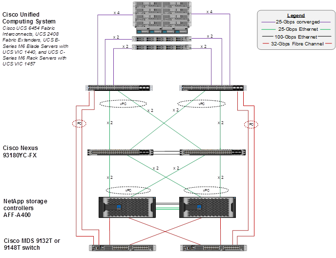
This infrastructure option expanded with Cisco MDS switches sitting between the Cisco UCS Fabric Interconnect and the NetApp AFF A400 to provide FC-booted hosts with 32 Gb FC block-level access to shared storage. The reference architecture reinforces the "wire-once" strategy, because as additional storage is added to the architecture, no re-cabling is required from the hosts to the Cisco UCS fabric interconnect.
The reference 25 Gb based hardware configuration includes:
● Two Cisco Nexus 93180YC-FX switches
● Two Cisco UCS 6454 fabric interconnects with Cisco UCS 2408 fabric extenders
● Two Cisco MDS 9132T multilayer fabric switches
● One NetApp AFF A400 (HA pair) running ONTAP 9.9.1 with NVMe SSD drives in disk shelves
Figure 10 shows the VMware vSphere built on FlexPod components and the network connections for a configuration with the Cisco UCS 6454 Fabric Interconnects and 100 Gb Ethernet core networking. This design is supported, was validated in previous FlexPod CVDs, and has port-channeled 25 Gb Ethernet connections between the Cisco UCS 5108 Blade Chassis and the Cisco UCS Fabric Interconnects, port-channeled 25 Gb Ethernet connections between the Cisco UCS C-Series rack-mounted servers and the Cisco UCS Fabric Interconnects, and 100 Gb Ethernet connections between the Cisco UCS Fabric Interconnect and Cisco Nexus 9000s, and between Cisco Nexus 9000s and NetApp AFF A800 storage array. This topology has been scaled up with 8 25 Gb Ethernet connections between the Cisco UCS 5108 Blade Chassis and the Cisco UCS Fabric Interconnects, 4 32 Gb FC connections between each Fabric Interconnect and MDS switch, and usage of 4 32 GB FC connections on each storage controller.
Figure 10. FlexPod Topology with 100 Gb Core Networking
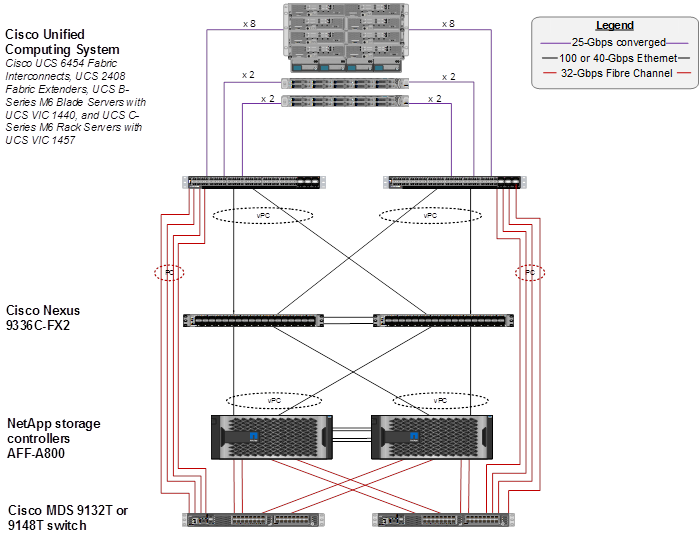
The reference architecture reinforces the "wire-once" strategy, because as additional storage is added to the architecture, no re-cabling is required from the hosts to the Cisco UCS fabric interconnect.
The reference 100 Gb based hardware configuration includes:
● Two Cisco Nexus 9336C-FX2 switches
● Two Cisco UCS 6454 fabric interconnects with Cisco UCS 2408 fabric extenders
● Two Cisco MDS 9132T multilayer fabric switches
● One NetApp AFF A400 (HA pair) running ONTAP 9.9.1 with internal NVMe SSD drives
Figure 11 shows a third topology with the VMware vSphere built on FlexPod components and the network connections for a configuration with the Cisco UCS 6454 Fabric Interconnects, 25 Gb Ethernet core networking and Cisco Nexus 93180YC-FX SAN Switching. This design was also validated and has port-channeled 25 Gb Ethernet connections between the Cisco UCS 5108 Blade Chassis and the Cisco UCS Fabric Interconnects, port-channeled 25 Gb Ethernet connections between the Cisco UCS C-Series rack-mounted servers and the Cisco UCS Fabric Interconnects, and 25 Gb Ethernet connections between the Cisco UCS Fabric Interconnect and Cisco Nexus 9000s, and between Cisco Nexus 9000s and the NetApp AFF A400 storage array.
Figure 11. FlexPod with Nexus 93180YC-FX SAN Switching Topology
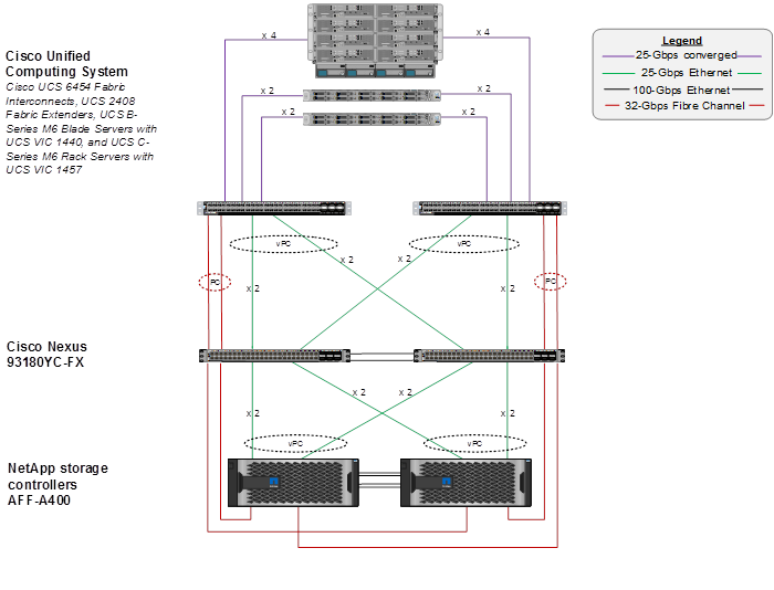
This infrastructure option uses the same Cisco Nexus 93180YC-FX switches sitting between the Cisco UCS Fabric Interconnect and the NetApp AFF A400 for SAN switching to provide FC-booted hosts with 32 Gb FC block-level access to shared storage. The reference architecture reinforces the "wire-once" strategy, because as additional storage is added to the architecture, no re-cabling is required from the hosts to the Cisco UCS fabric interconnect.
The reference Cisco Nexus 93180YC-FX SAN switching configuration includes:
● Two Cisco Nexus 93180YC-FX switches
● Two Cisco UCS 6454 fabric interconnects with Cisco UCS 2408 fabric extenders
● One NetApp AFF A400 (HA pair) running ONTAP 9.9.1 with internal NVMe SSD drives
SAN Boot
NetApp recommends implementing SAN boot for Cisco UCS Servers in the FlexPod Datacenter solution. Implementing SAN boot enables the operating system to be safely secured by the NetApp AFF storage system, providing better performance and flexibility. In this design, both iSCSI and Fibre Channel SAN boot are validated.
In iSCSI SAN boot, each Cisco UCS Server is assigned two iSCSI vNICs (one for each SAN fabric) that provide redundant connectivity all the way to the storage. The 25Gb Ethernet storage ports, in this example e0e-f and e0g-h, which are connected to the Nexus switches are grouped to form one logical port called an interface group (ifgroup) (in this example, a0a). The iSCSI virtual LANs (VLANs) are created on the ifgroup and the iSCSI LIFs are created on the iSCSI VLAN ports (in this example, a0a-<iSCSI-A-VLAN>). The iSCSI boot LUN is exposed to the servers through the iSCSI LIF by using igroups. This feature enables only the authorized server to have access to the boot LUN. See Figure 12 for the port and LIF layout.
Figure 12. iSCSI - SVM Ports and LIF Layout
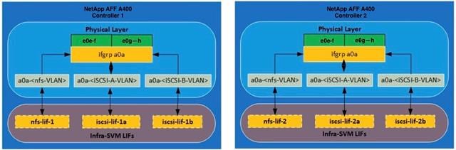
In the Fibre Channel SAN boot architecture, each Cisco UCS Server boots by connecting the NetApp AFF storage to the Cisco MDS switch. The 32Gb FC storage ports, in this example 2a and 2b, are connected to the Cisco MDS switch. The FC LIFs are created on the physical ports and each FC LIF is uniquely identified by its target WWPN. The storage system target WWPNs can be zoned with the server initiator WWPNs in the Cisco MDS switches. The FC boot LUN is exposed to the servers through the FC LIF by using the MDS switch. This feature enables only the authorized server to have access to the boot LUN. See Figure 13 for the port and LIF layout.
Figure 13. FC - SVM ports and LIF layout
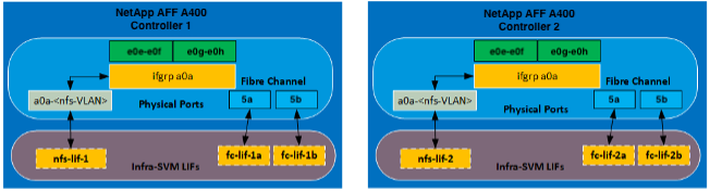
Unlike NAS network interfaces, the SAN network interfaces are not configured to fail over during a failure. Instead if a network interface becomes unavailable, the host chooses a new optimized path to an available network interface by communicating with the storage controllers via Asymmetric Logical Unit Access (ALUA). The ALUA protocol is an industry standard protocol supported by NetApp that is used to provide information about SCSI targets. This information enables a host to identify the optimal path to the storage.
iSCSI and FC: Network and Storage Connectivity
In the iSCSI design, the storage controller 100GbE ports are directly connected to Cisco Nexus 9336C-FX2 switches. Each controller is equipped with 100GbE cards in expansion bay 5 that have two physical ports. Each storage controller is connected to two SAN fabrics. This method provides increased redundancy to make sure that the paths from the host to its storage LUNs are always available. Figure 14 shows the port and interface assignment connection diagram for the AFF storage to the Cisco Nexus 9336C-FX2 network fabrics. This FlexPod design uses the following port and interface assignments. In this design, NFS and iSCSI traffic uses the 100GbE bandwidth.
Figure 14. iSCSI Connectivity
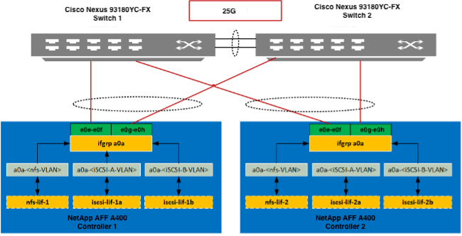
Fibre Channel (FC) Connectivity
In the FC design, the storage controller is connected to a Cisco MDS 9132T SAN switching infrastructure for FC boot and is connected to Cisco Nexus 93180YC-FX for all Ethernet traffic. Although smaller configurations can use the direct-attached, FC/FCoE storage method of the Cisco UCS fabric interconnect, the Cisco MDS provides increased scalability for larger configurations. The Cisco MDS has multiple Cisco UCS domains and the ability to connect to a data center SAN. An ONTAP storage controller uses N_Port ID virtualization (NPIV) to allow each network interface to log in to the FC fabric using a separate worldwide port name (WWPN). This feature allows a host to communicate with a FC target network interface, regardless of where that network interface is placed. To ensure that NPIV is enabled, use the ‘show npiv status’ command on the MDS switch. Each controller can be equipped with host bus adapters (HBA) that operate at 8Gb, 16Gb, and 32Gb FC. For the FC design, the FC HBA ports operate in FC target mode and the ports are connected to two SAN fabrics. This method provides increased redundancy to make sure that the paths from the host to its storage LUNs are always available. Figure 15 shows the port and interface assignment connection diagram for the AFF storage to the Cisco MDS 9132T SAN fabrics. This FlexPod design uses the following port and interface assignments. In this design, NFS uses 100GbE and FC uses the 32Gb bandwidth.
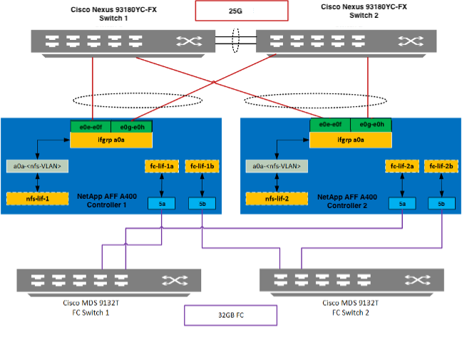
End-to-End FC-NVMe Connectivity
In the FC-NVMe design, the existing FC fabric used in the FC Connectivity design is reused. The FC and FC-NVME protocol can co-exist on the same link. The storage controller is connected to a Cisco MDS 9132T SAN switching infrastructure for FC transport.
For Connection FC-NVMe on the switch standard fibre channel zoning of FCNVMeInitiator vHBAs Initiator WWPN and Storage NVMe LIFs Target WWPN. For the Target mapping Host OS NVMe Qualified Name (NQN) is mapped to the NVMe NameSpace on the Storage Virtual Machine.
Figure 16. FC-NVMe Connectivity
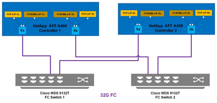
Cisco UCS Server Networking
In FlexPod, server networking generally uses the Cisco Virtual Interface Card (VIC). Other networking options are available and supported (https://www.cisco.com/c/en/us/products/interfaces-modules/unified-computing-system-adapters/index.html), but only Cisco 4th Generation VIC (1400 series) will be addressed in this section.
For Cisco UCS B-Series server networking with the Cisco UCS 6400 Series FI, the current IOM choices are the Cisco UCS 2408 Fabric Extender and the Cisco UCS 2204 and 2208 IOMs. The Cisco UCS 2408 provides up to eight 25 GE links on each fabric to the 10/25GE ports on the Cisco UCS 6400 Series FI, while the Cisco UCS 2204 and 2208 provide 10GE links. With the Cisco UCS VIC 1440 and 2408 Fabric Extender, the Port Expander card is now supported. Figure 17 shows Cisco UCS chassis connectivity of a Cisco UCS B200 M6 server with the Cisco UCS VIC 1440 and Port Expander. The Cisco UCS VIC 1440 is in the MLOM slot, and the Port Expander is in the Mezzanine slot. Two 10GE KR lanes connect between each Cisco UCS 2408 IOM and the MLOM slot. Two more 10GE KR lanes connect between each 2408 IOM and the Mezzanine slot. The Port Expander connects these two additional KR lanes from each IOM to the Cisco UCS VIC 1440. This combination of components along with timing of the KR lanes provides true 40GE vNICs/vHBAs, but individual network flows or TCP sessions on these vNICs have a maximum speed of 25Gbps since 25Gbps links are used in the port channel between the Cisco UCS 2408 IOM and the FI. Multiple flows can provide an aggregate speed of 40Gbps to each IOM or 80Gbps to the server. The Cisco UCS 2408 Fabric Extender can provide up to 200 Gbps from the servers in the chassis to each Cisco UCS 6400 Series FI. It is recommended to use Cisco UCS VIC 1440 plus Port Expander in most use cases including FC-NVMe with 32 Gbps FC.
Figure 17. Cisco UCS Chassis Connectivity – Cisco UCS VIC 1440 and Port Expander with Cisco UCS 2408 IOM
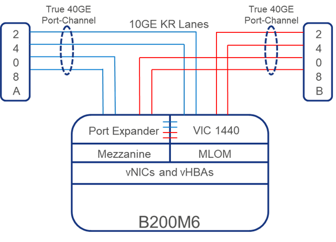
Figure 18 shows Cisco UCS chassis connectivity of a Cisco UCS B200 M6 server with only the Cisco UCS VIC 1440. The Cisco UCS VIC 1440 is in the MLOM slot. Two 10GE KR lanes connect between each Cisco UCS 2408 or 2208 IOM and the MLOM slot. This combination of components provides 20GE vNICs/vHBAs, but individual network flows or TCP sessions on these vNICs have a maximum speed of 10Gbps. Multiple flows can provide an aggregate speed of 20Gbps to each IOM or 40Gbps to the server. Note that if the Cisco UCS 2208 IOM were used here the vNICs and flow limit would be the same, but the Cisco UCS 2208 has up to 8 10GE links to the fabric interconnect where the Cisco UCS 2408 has up to 8 25GE links. If the Cisco UCS 2204 IOM were used here, the MLOM slot would have one KR lane instead of 2, and the vNICs/vHBAs would be 10GE with a total of 20Gbps to the server.
Figure 18. Cisco UCS Chassis Connectivity – Cisco UCS VIC 1440 only with Cisco UCS 2408 IOM
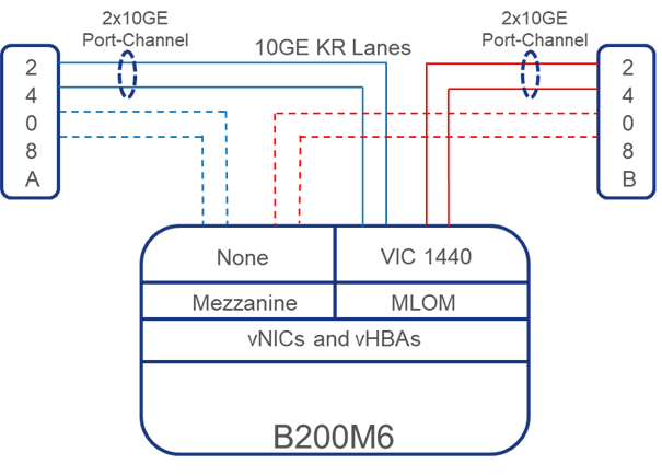
Figure 19 shows another option in Cisco UCS Chassis connectivity to a Cisco UCS B-Series server with Cisco UCS 6400 Series FIs along with the Cisco UCS 2408 IOM and the Cisco UCS VIC 1440 plus Cisco UCS VIC1480. This combination of components provides 20GE (2x10GE) vNICs, but they can be spread across the two network cards and have two sets of physical network connections. Individual network flows or TCP sessions on these vNICs have a maximum speed of 10Gbps, but multiple flows can provide an aggregate speed of 40Gbps to each IOM or 80Gbps to the server. Note that if the Cisco UCS 2208 IOM were used here the vNICs and flow limit would be the same, but the Cisco UCS 2208 has up to 8 10GE links to the fabric interconnect where the Cisco UCS 2408 has up to 8 25GE links. If the Cisco UCS 2204 IOM were used here, each server slot (MLOM and Mezzanine) would have one KR lane instead of 2, and the vNICs/vHBAs would be 10GE with a total of 40Gbps to the server.
Figure 19. Cisco UCS Chassis Connectivity – Cisco UCS VIC 1440 plus Cisco UCS VIC 1480 with Cisco UCS 2408 IOM
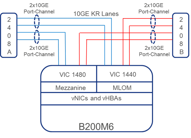
Cisco UCS VIC 1467, VIC 1455 and Cisco UCS VIC 1457 are supported with Cisco UCS C-Series servers directly connected to the Cisco UCS 6400 Series FIs. These VICs each have four 10/25GE interfaces with up to two connecting to each fabric interconnect. The connections from the fabric interconnects to the VIC are either single link or dual link port channels. If 25GE interfaces on all four links are used, vNICs/vHBAs are 50Gbps, with an aggregate of 100Gbps to each server. Individual network flows or TCP sessions on these vNICs have a maximum speed of 25Gbps.
![]() When using Cisco UCS VIC 1467, VIC 1455 and Cisco UCS VIC 1457 with Cisco UCS 6300 fabric interconnects, only single link port channels, or one 10GE connection to each fabric interconnect is supported.
When using Cisco UCS VIC 1467, VIC 1455 and Cisco UCS VIC 1457 with Cisco UCS 6300 fabric interconnects, only single link port channels, or one 10GE connection to each fabric interconnect is supported.
Cisco VIC Virtual Network Interface Card (vNIC) Ethernet Adapter Policy
The Ethernet adapter policy governs the host-side behavior of the vNIC, including how the adapter handles traffic. For example, you can use these policies to change default settings for queues, interrupt handling, performance enhancement, receive side scaling (RSS) hash. Cisco UCS provides a default set of Ethernet adapter policies. These policies include the recommended settings for each supported server operating system. Operating systems are sensitive to the settings in these policies.
A custom VMware-HighTrf Ethernet adapter policy was configured for this implementation according to the section “Configuring an Ethernet Adapter Policy to Enable eNIC Support for RSS on VMware ESXi” in the Cisco UCS Manager Network Management Guide, Release 4.2. This policy is designed to provide higher performance on vNICs with a large number of TCP sessions by providing multiple receive queues serviced by multiple CPUs.
Figure 20. VMware-HighTrf Ethernet Adapter Policy
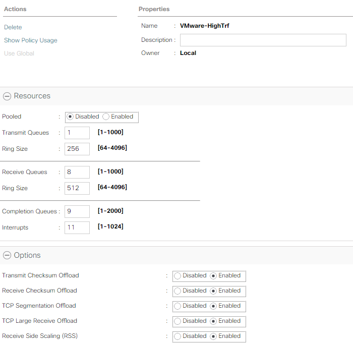
ESXi Host vNIC Layout
FlexPod uses a VMware Virtual Distributed Switch (vDS) for primary virtual switching, with additional Cisco UCS vNICs created when using Fibre Channel boot in the deployment as shown below in Figure 21.
Figure 21. vNIC Design with Fibre Channel Boot
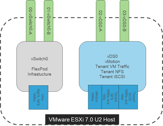
For the Fibre Channel boot implementation, four vNICs are defined, two for vSwitch0 and two for vDS0. vSwitch0 is defined during VMware ESXi host configuration and contains the FlexPod infrastructure management VLAN and the FlexPod infrastructure NFS VLAN. The ESXi host VMkernel (VMK) ports for management and infrastructure NFS are placed on vSwitch0. An infrastructure management virtual machine port group is also placed on vSwitch0 and the vCenter virtual machine’s management interface is placed here. vCenter is placed on vSwitch0 instead of the vDS because if the FlexPod infrastructure is shut down or power cycled and vCenter is attempted to be brought up on a host other than the host it was originally running on, it will boot up fine on the network on vSwitch0. If vCenter were on the vDS and moved to another host then booted, it would not be connected to the network after boot up.
The vDS contains port groups for tenant iSCSI and NFS VMKs and VMs (for in-guest iSCSI and NFS), tenant management and virtual machine (VM) networks, and vMotion VMKs. Previous versions of this design also included the infrastructure management VM network on the vDS, but that is left only on vSwitch0 in this design to provide simplicity in the design. The vDS uplinks also have the VMware-HighTrf UCS Ethernet Adapter Policy, providing more queuing and throughput on the adapters. The vMotion VMK is placed on the vDS after the host is added to the vDS. Placing the vMotion VMK on the vDS allows QoS to be applied to vMotion if necessary, in the future. vMotion is also pinned to the switching fabric B uplink with the fabric A uplink as standby using the port group’s Teaming and Failover policy to ensure that vMotion is normally only switched in the fabric B FI. Infrastructure NFS can optionally be placed on the vDS for higher performance but can be left on vSwitch0 for administrative simplicity. The VMware-HighTrf UCS Ethernet Adapter Policy can also be assigned to the vSwitch0 vNICs for higher performance from vSwitch0. Tenant iSCSI port groups should be pinned to the appropriate switching fabric uplink with the other fabric uplink set as unused. Within the vDS, as additional tenants are added, port groups can be added as necessary. The corresponding VLANs will also need to be added in Cisco UCS Manager and to the vDS vNIC templates. On both vSwitch0 and the vDS, all port groups initially use the Route based on originating virtual port hashing method. If multiple ports in the same port group are configured on a VM, or for better VMK distribution, consider using the Route based on source MAC hash method. Do not use the Route based on IP hash method since that method requires port channeling configuration on the connected switch ports.
A change that was implemented in this design was that the IB-MGMT VLAN was set as the native VLAN on the vSwitch0 vNICs in UCS Manager. This change, much like the setup iSCSI vNICs below, does not require the assignment of a VLAN on the VMkernel port setup. This change also allows DHCP to be used with these interfaces on first boot, allowing automated installation of VMware ESXi to be setup in the future.
Additional tenant vDSs can be deployed with dedicated vNIC uplinks, allowing for RBAC of the visibility and/or adjustment of the vDS to the respective tenant manager in vCenter. Tenant networks do not have a requirement to exist in separate vDSs and can optionally be pulled into the design shown above that was used in the validation of this FlexPod release.
In the iSCSI boot implementation, two additional iSCSI boot vSwitches are added as shown in Figure 22. Cisco UCS iSCSI boot requires separate vNICs for iSCSI boot. These vNICs use the appropriate fabric’s iSCSI VLAN as the native VLAN and are attached to the appropriate iSCSI boot vSwitch as shown. An iSCSI boot vDS can also be added and used or iSCSI can be migrated to port groups with assigned VLANs on vDS0.
Figure 22. vNIC Design with iSCSI Boot
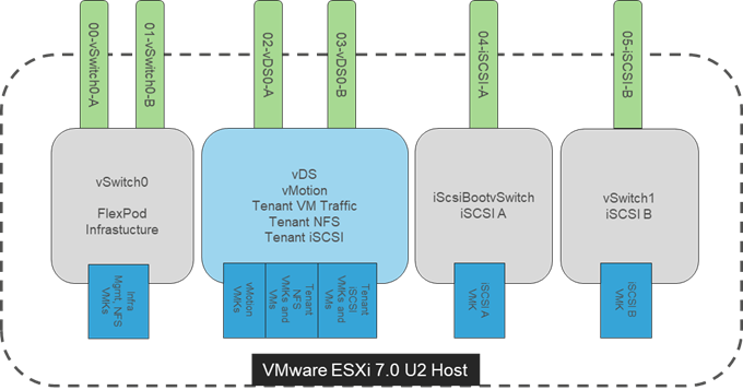
End-to-End Fibre Channel Network Connectivity
The Cisco MDS 9132T is the key component bringing together the 32Gbps Fibre Channel capabilities of the other pieces of this design. Redundant 32 Gbps Fibre Channel links extend from the MDS 9132Ts to both the storage controllers and the Cisco UCS 6454 FIs. Passage of this traffic shown in Figure 23 from left to right is as follows:
● Coming from the Cisco UCS B200 M6 server, equipped with a Cisco UCS VIC 1440 adapter and port expander, allowing for 40Gb on each side of the fabric (A/B) into the server.
● Pathing as a true 40Gb port channel through four timed 10Gb KR lanes of the Cisco UCS 5108 Chassis backplane into the Cisco UCS 2408 IOM (Fabric Extender).
● Connecting from each IOM to the Fabric Interconnect with up to eight 25Gb links automatically configured as port channels during chassis association.
● Continuing from the Cisco UCS 6454 Fabric Interconnects into the Cisco MDS 9132T with a 64Gbps (2x32Gbps) SAN port channel.
● Ending at the AFF A400 Controllers with 32Gbps Fibre Channel links.
Figure 23. FC End-to-End Design with Cisco UCS B200 M6 and Port Expander

The equivalent view for a Cisco UCS C220 M6 or C225 M6 server is shown in Figure 24. The main difference is that the two 25Gbps interfaces are connected directly between the Cisco UCS VIC 1467 and the FI and are port-channeled into a 50Gbps interface. In this case, a given FC flow is limited to 25 Gbps:
Figure 24. FC End-to-End Design with Cisco UCS C220/C225 M6
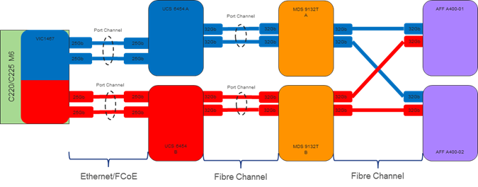
End-to-End IP Network Connectivity
The Cisco Nexus 9000 is the key component bringing together the port-channeled 25Gbps capabilities of the other pieces of this design. vPCs extend to both the AFF A400 Controllers and the Cisco UCS 6454 Fabric Interconnects. Passage of this traffic shown in Figure 25 from left to right is as follows:
● Coming from the Cisco UCS B200 M6 server, equipped with a Cisco UCS VIC 1440 adapter and port expander, allowing for 40Gb on each side of the fabric (A/B) into the server.
● Pathing as a true 40Gb port channel through timed 10Gb KR lanes of the Cisco UCS 5108 Chassis backplane into the Cisco UCS 2408 IOM (Fabric Extender).
● Connecting from each IOM to the Fabric Interconnect with up to eight 25Gb links automatically configured as port channels during chassis association.
● Continuing from the Cisco UCS 6454 Fabric Interconnects into the Cisco Nexus 93180YC-FX with a bundle of 25Gb ports presenting each side of the fabric from the Nexus pair as a common switch using a vPC.
● Ending at the AFF A400 Controllers with 25Gb bundled vPCs from the Nexus switches now carrying both sides of the fabric.
● Although a given flow is limited to 25 Gbps, multiple flows can exhaust the available bandwidth.
Figure 25. vPC, AFF A400 Controllers, and Cisco UCS 6454 Fabric Interconnect Traffic
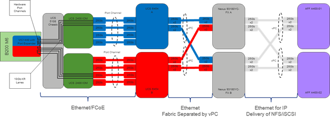
The equivalent view for a Cisco UCS C-Series server is shown in Figure 26. The main difference is that the two 25Gbps interfaces are connected directly between the Cisco UCS VIC 1467 and the FI and are port-channeled into a 50Gbps interface. In this case, a given flow is limited to 25 Gbps:
Figure 26. Cisco UCS C-Series Server
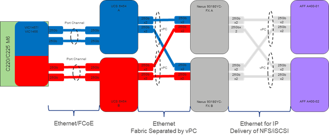
UEFI Secure Boot
This validation of FlexPod continues usage of UEFI Secure Boot. Unified Extensible Firmware Interface (UEFI) is a specification that defines a software interface between an operating system and platform firmware. Cisco UCS Manager uses UEFI to replace the BIOS firmware interfaces. This allows the BIOS to run in UEFI mode while still providing legacy support. When UEFI secure boot is enabled, all executables, such as boot loaders and adapter drivers, are authenticated by the BIOS before they can be loaded. Additionally, in this validation Trusted Platform Modules (TPMs) 2.0 were installed in the Cisco UCS B200 M6 servers used. VMware ESXi 7.0 U2 supports UEFI Secure Boot. VMware vCenter 7.0 U2 supports UEFI Secure Boot Attestation between the TPM 2.0 module and ESXi, validating that UEFI Secure Boot has properly taken place.
A high-level summary of the FlexPod Datacenter Design validation is provided in this section. The solution was validated for basic data forwarding by deploying virtual machines running the IOMeter tool. The system was validated for resiliency by failing various aspects of the system under load. Examples of the types of tests executed include:
● Failure and recovery of FC booted ESXi hosts in a cluster
● Rebooting of FC booted hosts
● Service Profile migration between blades
● Failure of partial and complete IOM links
● Failure and recovery of FC paths to AFF nodes, MDS switches, and fabric interconnects
● Storage link failure between one of the AFF nodes and the Cisco MDS
● Load was generated using the IOMeter tool and different IO profiles were used to reflect the different profiles that are seen in customer networks
Validated Hardware and Software
Table 1 lists the hardware and software versions used during solution validation. It is important to note that Cisco, NetApp, and VMware have interoperability matrixes that should be referenced to determine support for any specific implementation of FlexPod. Click the following links for more information:
● NetApp Interoperability Matrix Tool: http://support.netapp.com/matrix/
● Cisco UCS Hardware and Software Interoperability Tool: http://www.cisco.com/web/techdoc/ucs/interoperability/matrix/matrix.html
● VMware Compatibility Guide: http://www.vmware.com/resources/compatibility/search.php
Table 1. Validated Software Revisions
| Layer |
Device |
Image |
Comments |
| Compute |
Cisco UCS Fabric Interconnects 6454, UCS 2408 Fabric Extenders, UCS B-200 M6 Servers |
4.2(1f) |
Includes Cisco UCS Manager, Cisco UCS VIC 1440, and Port Expander |
| Network |
Cisco Nexus 93180YC-FX NX-OS |
9.3(8) |
|
|
|
Cisco MDS 9132T |
8.4(2c) |
|
| Storage |
NetApp AFF A400 |
ONTAP 9.9.1P1 |
Also validated with ONTAP 9.8P5 |
| Software |
Cisco UCS Manager |
4.2(1f) |
|
|
|
VMware vSphere |
7.0U2 |
|
|
|
VMware ESXi nfnic FC Driver |
5.0.0.12 |
|
|
|
VMware ESXi nenic Ethernet Driver |
1.0.35.0 |
|
|
|
Cisco UCS Manager Plugin for VMware vCenter |
3.0.5 |
|
|
|
Cisco Data Center Network Manager (SAN) |
11.5(1) |
|
|
|
NetApp ONTAP Tools |
9.8 |
|
|
|
NetApp NFS Plug-in for VMware VAAI |
2.0 |
|
|
|
NetApp SnapCenter plugin for VMware vSphere |
4.5 |
Stand-alone, no SnapCenter server required. |
|
|
NetApp Active IQ Unified Manager |
9.9P1 |
|
FlexPod Datacenter with VMware vSphere 7.0 U2 is the optimal shared infrastructure foundation to deploy a variety of IT workloads that is future proofed with 32 Gbps FC or 25Gbps Ethernet connectivity. Cisco and NetApp have created a platform that is both flexible and scalable for multiple use cases and applications. From virtual desktop infrastructure to SAP®, FlexPod can efficiently and effectively support business-critical applications running simultaneously from the same shared infrastructure. The flexibility, scalability and power of automation of FlexPod also enables customers to start out with a right-sized infrastructure that can ultimately grow with and adapt to their evolving business requirements.
Cisco Unified Computing System:
http://www.cisco.com/en/US/products/ps10265/index.html
Cisco UCS 6454 Fabric Interconnect:
Cisco UCS 5100 Series Blade Server Chassis:
http://www.cisco.com/en/US/products/ps10279/index.html
Cisco UCS B-Series Blade Servers:
http://www.cisco.com/en/US/partner/products/ps10280/index.html
Cisco UCS C-Series Rack Mount Servers:
http://www.cisco.com/c/en/us/products/servers-unified-computing/ucs-c-series-rack-servers/index.html
Cisco UCS Adapters:
http://www.cisco.com/en/US/products/ps10277/prod_module_series_home.html
Cisco UCS Manager:
http://www.cisco.com/en/US/products/ps10281/index.html
Cisco Nexus 9000 Series Switches:
http://www.cisco.com/c/en/us/products/switches/nexus-9000-series-switches/index.html
Cisco MDS 9000 Multilayer Fabric Switches:
Cisco MDS 9132T 32-Gbps 32-Port Fibre Channel Switch:
VMware vCenter Server:
http://www.vmware.com/products/vcenter-server/overview.html
VMware vSphere:
https://www.vmware.com/products/vsphere
NetApp ONTAP 9:
http://www.netapp.com/us/products/platform-os/ontap/index.aspx
NetApp AFF A-Series:
http://www.netapp.com/us/products/storage-systems/all-flash-array/aff-a-series.aspx
NetApp OnCommand:
http://www.netapp.com/us/products/management-software/
NetApp VSC:
http://www.netapp.com/us/products/management-software/vsc/
NetApp NFS Plug-in for VMware VAAI 1.1.2:
https://mysupport.netapp.com/documentation/productlibrary/index.html?productID=61278
NetApp SnapCenter:
https://www.netapp.com/us/products/backup-recovery/snapcenter-backup-management.aspx
Cisco UCS Hardware Compatibility Matrix:
https://ucshcltool.cloudapps.cisco.com/public/
VMware and Cisco Unified Computing System:
http://www.vmware.com/resources/compatibility
NetApp Interoperability Matrix Tool:
http://support.netapp.com/matrix/
John George, Technical Marketing Engineer, Data Center Solutions Engineering, Cisco Systems, Inc.
John has been involved in designing, developing, validating, and supporting the FlexPod Converged Infrastructure since it was developed over ten years ago. Before his roles with FlexPod, he supported and administered a large worldwide training network and VPN infrastructure. John holds a Master's degree in Computer Engineering from Clemson University.
Sree Lakshmi Lanka, Senior Solutions Architect, Infrastructure and Cloud Engineering, NetApp
Sree is a Senior Solutions Architect at NetApp. She has more than 12 years of experience in data center infrastructure solutions, both in traditional and in hybrid/public cloud space. She collaborates with marketing, product management and engineering teams to develop and deliver technical marketing product material, which includes reference architectures, technical reports, presentations, blogs, demo videos and white papers. This material is aimed at educating customers, partners, or sales team. She has a bachelor’s degree in Computer Science and an artist in the field of Kuchipudi dance, an Indian classical dance form from Andhra Pradesh. She enjoys organic gardening, hiking, and running.
For their support and contribution to the design, validation, and creation of this Cisco Validated Design, the authors would like to thank:
● Haseeb Niazi, Technical Marketing Engineer, Cisco Systems, Inc.
● Arvind Ramakrishnan, Sr. Technical Marketing Engineer, NetApp
● Kamini Singh, Technical Marketing Engineer, NetApp
● Kishore Esanakula, Sr. Technical Marketing Engineer, NetApp
For comments and suggestions about this guide and related guides, join the discussion on Cisco Community at https://cs.co/en-cvds.