FlexPod Datacenter with Cisco UCS 4.2(1) in UCS Managed Mode, VMware vSphere 7.0 U2, and NetApp ONTAP 9.9
Available Languages
Bias-Free Language
The documentation set for this product strives to use bias-free language. For the purposes of this documentation set, bias-free is defined as language that does not imply discrimination based on age, disability, gender, racial identity, ethnic identity, sexual orientation, socioeconomic status, and intersectionality. Exceptions may be present in the documentation due to language that is hardcoded in the user interfaces of the product software, language used based on RFP documentation, or language that is used by a referenced third-party product. Learn more about how Cisco is using Inclusive Language.
- US/Canada 800-553-2447
- Worldwide Support Phone Numbers
- All Tools
 Feedback
 Feedback

FlexPod Datacenter with Cisco UCS 4.2(1) in UCS Managed Mode, VMware vSphere 7.0 U2, and NetApp ONTAP 9.9
Deployment Guide for FlexPod Datacenter with Cisco UCS Managed M6 Servers, VMware vSphere 7.0 U2, and NetApp ONTAP 9.9
Published: March 2022

In partnership with
![]()
About the Cisco Validated Design Program
The Cisco Validated Design (CVD) program consists of systems and solutions designed, tested, and documented to facilitate faster, more reliable, and more predictable customer deployments. For more information, go to:
http://www.cisco.com/go/designzone.
ALL DESIGNS, SPECIFICATIONS, STATEMENTS, INFORMATION, AND RECOMMENDATIONS (COLLECTIVELY, "DESIGNS") IN THIS MANUAL ARE PRESENTED "AS IS," WITH ALL FAULTS. CISCO AND ITS SUPPLIERS DISCLAIM ALL WARRANTIES, INCLUDING, WITHOUT LIMITATION, THE WARRANTY OF MERCHANTABILITY, FITNESS FOR A PARTICULAR PURPOSE AND NONINFRINGEMENT OR ARISING FROM A COURSE OF DEALING, USAGE, OR TRADE PRACTICE. IN NO EVENT SHALL CISCO OR ITS SUPPLIERS BE LIABLE FOR ANY INDIRECT, SPECIAL, CONSEQUENTIAL, OR INCIDENTAL DAMAGES, INCLUDING, WITHOUT LIMITATION, LOST PROFITS OR LOSS OR DAMAGE TO DATA ARISING OUT OF THE USE OR INABILITY TO USE THE DESIGNS, EVEN IF CISCO OR ITS SUPPLIERS HAVE BEEN ADVISED OF THE POSSIBILITY OF SUCH DAMAGES.
THE DESIGNS ARE SUBJECT TO CHANGE WITHOUT NOTICE. USERS ARE SOLELY RESPONSIBLE FOR THEIR APPLICATION OF THE DESIGNS. THE DESIGNS DO NOT CONSTITUTE THE TECHNICAL OR OTHER PROFESSIONAL ADVICE OF CISCO, ITS SUPPLIERS OR PARTNERS. USERS SHOULD CONSULT THEIR OWN TECHNICAL ADVISORS BEFORE IMPLEMENTING THE DESIGNS. RESULTS MAY VARY DEPENDING ON FACTORS NOT TESTED BY CISCO.
CCDE, CCENT, Cisco Eos, Cisco Lumin, Cisco Nexus, Cisco StadiumVision, Cisco TelePresence, Cisco WebEx, the Cisco logo, DCE, and Welcome to the Human Network are trademarks; Changing the Way We Work, Live, Play, and Learn and Cisco Store are service marks; and Access Registrar, Aironet, AsyncOS, Bringing the Meeting To You, Catalyst, CCDA, CCDP, CCIE, CCIP, CCNA, CCNP, CCSP, CCVP, Cisco, the Cisco Certified Internetwork Expert logo, Cisco IOS, Cisco Press, Cisco Systems, Cisco Systems Capital, the Cisco Systems logo, Cisco Unified Computing System (Cisco UCS), Cisco UCS B-Series Blade Servers, Cisco UCS C-Series Rack Servers, Cisco UCS S-Series Storage Servers, Cisco UCS Manager, Cisco UCS Management Software, Cisco Unified Fabric, Cisco Application Centric Infrastructure, Cisco Nexus 9000 Series, Cisco Nexus 7000 Series. Cisco Prime Data Center Network Manager, Cisco NX-OS Software, Cisco MDS Series, Cisco Unity, Collaboration Without Limitation, EtherFast, EtherSwitch, Event Center, Fast Step, Follow Me Browsing, FormShare, GigaDrive, HomeLink, Internet Quotient, IOS, iPhone, iQuick Study, LightStream, Linksys, MediaTone, MeetingPlace, MeetingPlace Chime Sound, MGX, Networkers, Networking Academy, Network Registrar, PCNow, PIX, PowerPanels, ProConnect, ScriptShare, SenderBase, SMARTnet, Spectrum Expert, StackWise, The Fastest Way to Increase Your Internet Quotient, TransPath, WebEx, and the WebEx logo are registered trademarks of Cisco Systems, Inc. and/or its affiliates in the United States and certain other countries. (LDW_U1)
All other trademarks mentioned in this document or website are the property of their respective owners. The use of the word partner does not imply a partnership relationship between Cisco and any other company. (0809R)
© 2022 Cisco Systems, Inc. All rights reserved.
Contents
Deployment Hardware and Software
Ansible Automation Workflow and Solution Deployment
Storage Configuration – ONTAP Boot Storage Setup
Storage Configuration – ONTAP NVMe Namespace Mapping and Finalizing ONTAP Storage
FlexPod Management Tools Setup
Cisco Validated Designs (CVDs) include systems and solutions that are designed, tested, and documented to facilitate and improve customer deployments. These designs incorporate a wide range of technologies and products into a portfolio of solutions that have been developed to address the business needs of customers. Cisco and NetApp have partnered to deliver FlexPod®, which serves as the foundation for a variety of workloads and enables efficient architectural designs that are based on customer requirements. A FlexPod solution is a validated approach for deploying Cisco and NetApp technologies as a shared cloud infrastructure.
Hybrid cloud adoption is accelerating and FlexPod is at the center of on premises infrastructure. As business applications move into the cloud, management applications must also follow suit where practical. In this updated design, FlexPod is introducing SaaS based management with Cisco Intersight and NetApp® Active IQ. These platforms offer AI powered analytics for infrastructure management and operational intelligence.
This document describes the Cisco and NetApp FlexPod Datacenter with NetApp ONTAP® 9.9 on NetApp AFF A400 all-flash storage system, Cisco UCS Manager unified software release 4.2(1) with 3rd Generation Intel Xeon Scalable Processors in Cisco UCS M6 Servers and VMware vSphere 7.0 Update 2. Cisco UCS Manager (UCSM) 4.2(1) provides consolidated support of all current Cisco UCS Fabric Interconnect models (6200, 6300, 6324 (Cisco UCS Mini)), 6400, 2200/2300/2400 series IOM, Cisco UCS B-Series, and Cisco UCS C-Series. Also included are Cisco Intersight and NetApp Active IQ SaaS management platforms. FlexPod Datacenter with NetApp ONTAP 9.9.1, Cisco UCS unified software release 4.2(1), and VMware vSphere 7.0 Update 2 is a predesigned, best-practice datacenter architecture built on the Cisco Unified Computing System (Cisco UCS), the Cisco Nexus® 9000 family of switches, MDS 9000 multilayer fabric switches, and NetApp AFF A-Series storage arrays running ONTAP 9.9.1 data management software.
The current industry trend in datacenter design is towards shared infrastructures. By using virtualization along with pre-validated IT platforms, enterprise customers have embarked on the journey to the cloud by moving away from application silos and toward shared infrastructure that can be quickly deployed, thereby increasing agility, and reducing costs. Cisco and NetApp have partnered to deliver FlexPod, which uses best of breed storage, server, and network components to serve as the foundation for a variety of workloads, enabling efficient architectural designs that can be quickly and confidently deployed.
The audience for this document includes, but is not limited to; sales engineers, field consultants, professional services, IT managers, partner engineers, and customers who want to take advantage of an infrastructure built to deliver IT efficiency and enable IT innovation.
This document provides a step-by-step configuration and implementation guide for the FlexPod Datacenter with Cisco UCS Fabric Interconnects, NetApp AFF storage, Cisco MDS, and Cisco Nexus 9000 solution.
The primary FlexPod Datacenter with VMware vSphere 7.0 Update 2 validated design introduced new hardware and software into the portfolio, enabling 10/25/40/100GbE along with native 32Gb FC via the Cisco MDS Fibre Channel switch or the Cisco Nexus 93180YC-FX switch. This primary design has been updated to include the latest Cisco and NetApp hardware and software as follows:
● Support for the Cisco UCS 4.2(1) unified software release, Cisco UCS B200-M6 and C220-M6 servers with 3rd Generation Intel Xeon Scalable Processors and Cisco UCS C225-M6 servers with AMD EPYC 3rd Generation Processors, all with Cisco 1400 Series Virtual Interface Cards (VICs)
● Support for 200 Series Intel Optane Persistent Memory in Memory Mode with specific memory configurations and App Direct Mode
● Configuration of the Cisco Nexus switches, NetApp storage, Cisco UCS, Cisco MDS switches, VMware ESXi and vCenter, NetApp ONTAP Tools, and NetApp AIQUM with Ansible playbooks
● Cisco UCS Best Practice Recommended Virtualization BIOS Policies for Intel-based M6, Intel-based M5, and AMD-based C125 servers
● Support for NVMe over Fibre Channel (FC-NVMe) VMware datastores
● Support for NFS 4.1 VMware datastores
● Support for NetApp FlexGroup datastores (NFS 3 and 4.1)
● Support for Cisco Intersight Integration with NetApp storage for storage inventory, monitoring, and orchestration
● Support Cisco Intersight Cloud Orchestrator (ICO), providing orchestration of NetApp storage, Cisco UCS servers, and VMware vCenter and ESXi
● Support for the Cisco UCS Manager Plugin for VMware vCenter 3.0.5
● Support for the latest release of NetApp ONTAP® 9.9.1
● Support for NetApp ONTAP Tools for VMware vSphere 9.8P2
● Support for NetApp SnapCenter and NetApp SnapCenter Plug-in for VMware vSphere Version 4.6
● Support for NetApp Active IQ Unified Manager 9.10
● Support for Cisco Nexus NX-OS System Software 9.3(8)
● Support for Cisco MDS NX-OS System Software 8.4(2c)
● Support for Cisco Data Center Network Manager (DCNM)-SAN Version 11.5(1)
Deployment Hardware and Software
FlexPod is a defined set of hardware and software that serves as an integrated foundation for both virtualized and non-virtualized solutions. VMware vSphere® built on FlexPod includes NetApp AFF storage, Cisco Nexus® networking, Cisco MDS storage networking, the Cisco Unified Computing System (Cisco UCS®), and VMware vSphere software in a single package. The design is flexible enough that the networking, computing, and storage can fit in one data center rack or be deployed according to a customer's data center design. Port density enables the networking components to accommodate multiple configurations of this kind.
One benefit of the FlexPod architecture is the ability to customize or "flex" the environment to suit a customer's requirements. A FlexPod can easily be scaled as requirements and demand change. The unit can be scaled both up (adding resources to a FlexPod unit) and out (adding more FlexPod units). The reference architecture detailed in this document highlights the resiliency, cost benefit, and ease of deployment of a Fibre Channel and IP-based storage solution. A storage system capable of serving multiple protocols across a single interface allows for customer choice and investment protection because it truly is a wire-once architecture.
Figure 1 shows the VMware vSphere built on FlexPod components and the network connections for a configuration with the Cisco UCS 6454 Fabric Interconnects. This design has port-channeled 25 Gb Ethernet connections between the Cisco UCS 5108 Blade Chassis and the Cisco UCS Fabric Interconnects via the Cisco UCS 2408 Fabric Extenders, port-channeled 25 Gb Ethernet connections between the C-Series rackmounts and the Cisco UCS Fabric Interconnects, and port-channeled 25 Gb Ethernet connections between the Cisco UCS Fabric Interconnects and Cisco Nexus 9000s, and between the Cisco Nexus 9000s and NetApp AFF A400 storage array. This infrastructure option expanded with Cisco MDS switches sitting between the Cisco UCS Fabric Interconnects and the NetApp AFF A400 to provide FC-booted hosts with 32 Gb FC block-level access to shared storage. The reference architecture reinforces the "wire-once" strategy, because as additional storage is added to the architecture, no re-cabling is required from the hosts to the Cisco UCS fabric interconnects.
Figure 1. FlexPod with Cisco UCS 6454 Fabric Interconnects and NetApp AFF A-Series
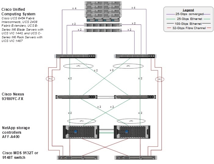
The reference 25Gb based hardware configuration includes:
● Two Cisco Nexus 93180YC-FX switches
● Two Cisco UCS 6454 fabric interconnects
● Two Cisco MDS 9132T multilayer fabric switches
● One NetApp AFF A400 or A800 (HA pair) running ONTAP 9.9.1 with NVMe SSD disks
Table 1 lists the software revisions for this solution.
| Layer |
Device |
Image |
Comments |
| Compute |
Cisco UCS Fabric Interconnects 6454, Cisco UCS M6 Servers |
4.2(1i) |
Includes the Cisco UCS Manager and Cisco UCS VIC 1440 |
| Network |
Cisco Nexus 93180YC-FX NX-OS |
9.3(8) |
|
|
|
Cisco MDS 9132T |
8.4(2c) |
|
| Storage |
NetApp AFF A400 |
ONTAP 9.9.1 |
Validated with ONTAP 9.8 and 9.9.1 |
| Software |
Cisco UCS Manager |
4.2(1i) |
|
|
|
UCS Manager Plugin for VMware vCenter |
3.0.5 |
|
|
|
Cisco Data Center Network Manager (SAN) |
11.5(1) |
With update with log4j patch |
|
|
Cisco Intersight Assist Appliance |
1.0.9-342 |
Will update to release with log4j patch |
|
|
VMware vSphere |
7.0 Update 2 |
With log4j workaround |
|
|
VMware ESXi nfnic FC Driver |
5.0.0.15 |
Supports FC-NVMe |
|
|
VMware ESXi nenic Ethernet Driver |
1.0.35.0 |
|
|
|
NetApp ONTAP Tools for VMware vSphere |
9.8P2 |
formerly Virtual Storage Console (VSC) with log4j patch |
|
|
NetApp NFS Plug-in for VMware VAAI |
2.0 |
|
|
|
NetApp SnapCenter for vSphere |
4.6 |
Includes the vSphere plug-in for SnapCenter with log4j patch |
|
|
NetApp Active IQ Unified Manager |
9.10 |
With log4j patch |
| Management |
Cisco Intersight |
N/A |
|
|
|
NetApp Active IQ |
N/A |
|
This document explains how to configure a fully redundant, highly available configuration for a FlexPod unit with ONTAP storage. Therefore, reference is made to which component is being configured with each step, either 01 or 02 or A and B. For example, node01 and node02 are used to identify the two NetApp storage controllers that are provisioned with this document, and Cisco Nexus A or Cisco Nexus B identifies the pair of Cisco Nexus switches that are configured. The Cisco UCS Fabric Interconnects are similarly configured. Additionally, this document details the steps for provisioning multiple Cisco UCS hosts, and these examples are identified as: VM-Host-Infra-01, VM-Host-Infra-02 to represent infrastructure hosts deployed to each of the fabric interconnects in this document. Finally, to indicate that you should include information pertinent to your environment in a given step, <text> appears as part of the command structure. See the following example for the network port vlan create command:
Usage:
network port vlan create ?
[-node] <nodename> Node
{ [-vlan-name] {<netport>|<ifgrp>} VLAN Name
| -port {<netport>|<ifgrp>} Associated Network Port
[-vlan-id] <integer> } Network Switch VLAN Identifier
Example:
network port vlan create -node <node01> -vlan-name a0a-<vlan id>
This document is intended to enable you to fully configure the customer environment. In this process, various steps require you to insert customer-specific naming conventions, IP addresses, and VLAN schemes, as well as to record appropriate MAC addresses. Table 2 describes the VLANs necessary for deployment as outlined in this guide.
| VLAN Name |
VLAN Purpose |
ID Used in Validating This Document |
Subnet Used in Validating This Document |
Default Gateway Used in Validating This Document |
| OOB-MGMT |
VLAN for out-of-band management interfaces |
13 |
192.168.156.0/24 |
192.168.156.254 |
| IB-MGMT |
VLAN for in-band management interfaces |
113 |
10.1.156.0/24 |
10.1.156.254 |
| Native-Vlan |
VLAN to which untagged frames are assigned |
2 |
|
|
| Infra-NFS |
VLAN for Infrastructure NFS traffic |
3050 |
192.168.50.0/24 |
|
| FCoE-A |
VLAN for FCoE encapsulation of VSAN-A |
101 |
|
|
| FCoE-B |
VLAN for FCoE encapsulation of VSAN-B |
102 |
|
|
| vMotion |
VLAN for VMware vMotion |
3000 |
192.168.0.0/24 |
|
| VM-Traffic |
VLAN for Production VM Interfaces |
900 |
10.10.156.0/24 |
10.10.156.254 |
| Infra-iSCSI-A (Appendix) |
VLAN for Infrastructure iSCSI Fabric A traffic and boot |
3010 |
192.168.10.0/24 |
|
| Infra-iSCSI-B (Appendix) |
VLAN for Infrastructure iSCSI Fabric B traffic and boot |
3020 |
192.168.20.0/24 |
|
Table 3 lists the VMs necessary for deployment as outlined in this document.
| Virtual Machine Description |
Host Name |
IP Address |
| vCenter Server |
|
|
| NetApp ONTAP Tools |
|
|
| NetApp SnapCenter for vSphere |
|
|
| Active IQ Unified Manager |
|
|
| Cisco Intersight Assist |
|
|
| Cisco Data Center Network Manager (DCNM) - SAN |
|
|
The information in this section is provided as a reference for cabling the physical equipment in a FlexPod environment. To simplify cabling requirements, a cabling diagram was used.
The cabling diagram in this section contains the details for the prescribed and supported configuration of the NetApp AFF 400 running NetApp ONTAP 9.9.1.
![]() For any modifications of this prescribed architecture, consult the NetApp Interoperability Matrix Tool (IMT).
For any modifications of this prescribed architecture, consult the NetApp Interoperability Matrix Tool (IMT).
This document assumes that out-of-band management ports are plugged into an existing management infrastructure at the deployment site. These interfaces will be used in various configuration steps.
![]() Be sure to use the cabling directions in this section as a guide.
Be sure to use the cabling directions in this section as a guide.
The NetApp storage controller and disk shelves should be connected according to best practices for the specific storage controller and disk shelves. For disk shelf cabling, refer to NetApp Support.
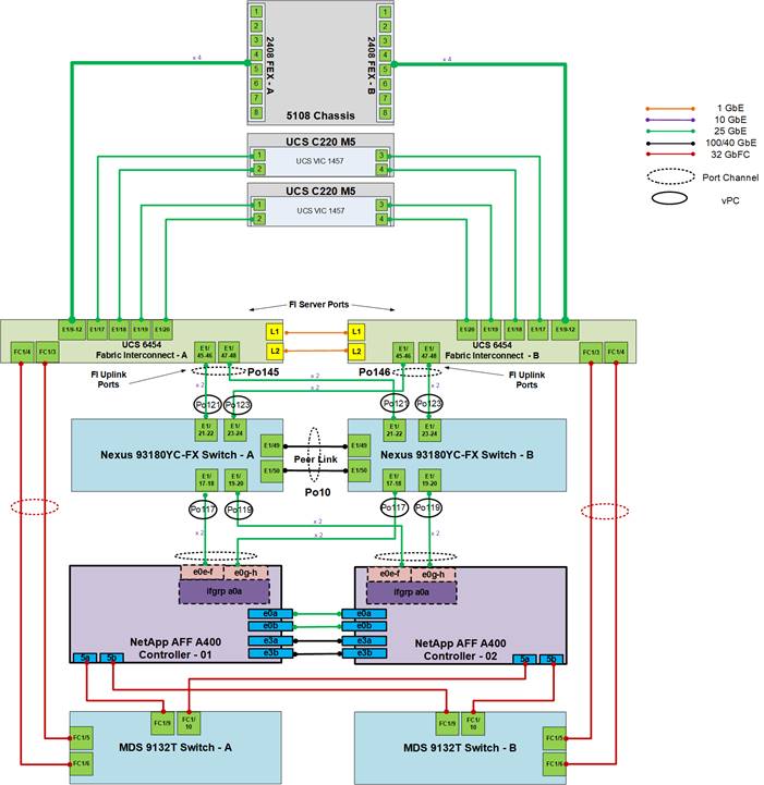
Figure 2 details the cable connections used in the validation lab for the FlexPod topology based on the Cisco UCS 6454 fabric interconnect. Two 32Gb uplinks connect as port-channels to each Cisco UCS Fabric Interconnect from the MDS switches, and a total of four 32Gb links connect the MDS switches to the NetApp AFF controllers. Also, 25Gb links connect the Cisco UCS Fabric Interconnects to the Cisco Nexus Switches and the NetApp AFF controllers to the Cisco Nexus Switches. Additional 1Gb management connections will be needed for an out-of-band network switch that sits apart from the FlexPod infrastructure. Each Cisco UCS fabric interconnect and Cisco Nexus switch is connected to the out-of-band network switch, and each AFF controller has a connection to the out-of-band network switch. Layer 3 network connectivity is required between the Out-of-Band (OOB) and In-Band (IB) Management Subnets.
Figure 2. FlexPod Cabling with Cisco UCS 6454 Fabric Interconnect
Ansible Automation Workflow and Solution Deployment
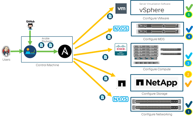
If using the published Ansible playbooks to configure the FlexPod infrastructure, complete this section of the document. If completing a manual configuration, skip to the next section of the document. The Ansible automated FlexPod solution uses a management workstation (control machine) to run Ansible playbooks to configure Cisco Nexus, NetApp ONTAP Storage, Cisco UCS, Cisco MDS, and VMware ESXi.
Figure 3 illustrates the FlexPod solution implementation workflow which is explained in the following sections. The FlexPod infrastructure layers are first configured in the order illustrated.
Figure 3. Ansible Automation Workflow
Prerequisites
Setup of the solution begins with a management workstation that has access to the Internet and with a working installation of Ansible. The management workstation commonly runs a variant of Linux or MacOS for ease of use with these command-line-based tools. Instructions for installing the workstation are not included in this document, but basic installation and configuration of Ansible is covered. A guide for getting started with Ansible can be found at the following link:
● Getting Started with Red Hat Ansible: https://www.ansible.com/resources/get-started
● To use the Ansible playbooks demonstrated in this document, the management workstation must also have a working installation of Git and access to the Cisco DevNet public GitHub repository. The Ansible playbooks used in this document are cloned from the public repositories, located at the following links:
◦ Cisco DevNet: https://developer.cisco.com/codeexchange/github/repo/ucs-compute-solutions/complete-link
◦ GitHub repository: https://github.com/ucs-compute-solutions/FlexPod-UCSM-M6
● The Cisco Nexus and MDS Switches, NetApp Storage and Cisco UCS must be physically racked, cabled, powered, and configured with management IP addresses before the Ansible-based installation procedure can begin as shown in the cabling diagram (Figure 2). If necessary, upgrade the Cisco Nexus Switches to release 9.3(8) and the Cisco UCS to 4.2(1f) with the default firmware packages for both blades and rack servers set to 4.2(1f).
● Before running each Ansible Playbook to setup the Network, Storage, Cisco UCS, and VMware ESXi various variables have to be updated based on the customers environment and specific implementation with values such as the VLANs, pools and ports on Cisco UCS, IP addresses for NFS and iSCSI interfaces and values needed for VMware ESXi.
![]() Day 2 Configuration tasks such as adding datastores or ESXi servers have been performed manually or with Cisco Intersight Cloud Orchestrator (ICO) and the information has been provided in the later sections of this document.
Day 2 Configuration tasks such as adding datastores or ESXi servers have been performed manually or with Cisco Intersight Cloud Orchestrator (ICO) and the information has been provided in the later sections of this document.
Prepare Management Workstation (Control Machine)
In this section, the installation steps are performed on the CentOS management host to prepare the host for solution deployment to support the automation of Cisco UCS, Cisco Nexus, NetApp Storage, Cisco MDS and VMware ESXi using Ansible Playbooks.
![]() The following steps were performed on a CentOS 8.4 Virtual Machine as the root user.
The following steps were performed on a CentOS 8.4 Virtual Machine as the root user.
To prepare the management workstation, follow these steps:
1. Install EPEL repository on the management host.
dnf install https://dl.fedoraproject.org/pub/epel/epel-release-latest-8.noarch.rpm
2. Install Ansible engine.
dnf install ansible
3. Verify Ansible version to make sure it is release 2.9 or later.
ansible --version
ansible 2.9.23
config file = /etc/ansible/ansible.cfg
configured module search path = ['/root/.ansible/plugins/modules', '/usr/share/ansible/plugins/modules']
ansible python module location = /usr/lib/python3.6/site-packages/ansible
executable location = /usr/bin/ansible
python version = 3.6.8 (default, Mar 19 2021, 08:58:41) [GCC 8.4.1 20200928 (Red Hat 8.4.1-1)]
4. Install UCS SDK.
pip3 install ucsmsdk
5. You should be able to SSH into each of the Cisco Nexus switches that we will configure using Ansible so that the SSH keys are cached.
ssh admin@192.168.156.21
The authenticity of host '192.168.156.21 (192.168.156.21)' can't be established.
RSA key fingerprint is SHA256:YWSl7OaDF7VbOqg9ImRTY2bwFXIrajHAKd/xoOwBCgk.
Are you sure you want to continue connecting (yes/no/[fingerprint])? yes
Warning: Permanently added '192.168.156.21' (RSA) to the list of known hosts.
User Access Verification
Password:
6. Install NetApp specific python modules.
pip3 install netapp-lib
7. Install ansible-galaxy collections for Cisco UCS, Cisco Nexus and NetApp as follows:
ansible-galaxy collection install cisco.nxos
ansible-galaxy collection install cisco.ucs
ansible-galaxy collection install netapp.ontap
ansible-galaxy collection install community.vmware
Clone GitHub Collection
You need to use a GitHub repository from one public location; the first step in the process is to clone the GitHub collection named FlexPod-UCSM-M6 (https://github.com/ucs-compute-solutions/FlexPod-UCSM-M6.git) to a new empty folder on the management workstation. Cloning the repository creates a local copy, which is then used to run the playbooks that have been created for this solution. To clone the GitHub repository, follow these steps:
1. From the management workstation, create a new folder for the project. The GitHub collection will be cloned in a new folder inside this one, named /root/FlexPod-UCSM-M6.
2. Open a command-line or console interface on the management workstation and change directories to the new folder just created.
3. Clone the GitHub collection using the following command:
git clone https://github.com/ucs-compute-solutions/FlexPod-UCSM-M6.git
4. Change directories to the new folder named FlexPod-UCSM-M6.
![]() Follow these steps precisely because failure to do so could result in an improper configuration.
Follow these steps precisely because failure to do so could result in an improper configuration.
Physical Connectivity
Follow the physical connectivity guidelines for FlexPod as explained in section FlexPod Cabling.
FlexPod Cisco Nexus Base
Before the Ansible Nexus switch setup playbook can be run, the Cisco Nexus switches must be brought up with a management IP address. The following procedures describe this basic configuration of the Cisco Nexus switches for use in a base FlexPod environment. This procedure assumes the use of Cisco Nexus 9000 9.3(8), the Cisco suggested Nexus switch release at the time of this validation.
![]() If using the Cisco Nexus 93180YC-FX switches for both LAN and SAN switching, please refer to section FlexPod with Cisco Nexus 93180YC-FX SAN Switching Configuration - Part 1 in the Appendix to execute the Cisco Nexus 93180YC-FX SAN Switching Base Configuration.
If using the Cisco Nexus 93180YC-FX switches for both LAN and SAN switching, please refer to section FlexPod with Cisco Nexus 93180YC-FX SAN Switching Configuration - Part 1 in the Appendix to execute the Cisco Nexus 93180YC-FX SAN Switching Base Configuration.
![]() The following procedure includes the setup of NTP distribution on both the mgmt0 port and the in-band management VLAN. The interface-vlan feature and ntp commands are used to set this up. This procedure also assumes that the default VRF is used to route the in-band management VLAN.
The following procedure includes the setup of NTP distribution on both the mgmt0 port and the in-band management VLAN. The interface-vlan feature and ntp commands are used to set this up. This procedure also assumes that the default VRF is used to route the in-band management VLAN.
![]() In this validation, port speed and duplex are hard set at both ends of every 100GE connection.
In this validation, port speed and duplex are hard set at both ends of every 100GE connection.
![]() This validation assumes that both switches have been reset to factory defaults by using the “write erase” command followed by the “reload” command.
This validation assumes that both switches have been reset to factory defaults by using the “write erase” command followed by the “reload” command.
Set Up Initial Configuration
Cisco Nexus A
To set up the initial configuration for the Cisco Nexus A switch on <nexus-A-hostname>, follow these steps from a serial console:
1. Configure the switch.
![]() On initial boot and connection to the serial or console port of the switch, the NX-OS setup should automatically start and attempt to enter Power on Auto Provisioning.
On initial boot and connection to the serial or console port of the switch, the NX-OS setup should automatically start and attempt to enter Power on Auto Provisioning.
Abort Power On Auto Provisioning [yes - continue with normal setup, skip - bypass password and basic configuration, no - continue with Power On Auto Provisioning] (yes/skip/no)[no]: yes
Disabling POAP.......Disabling POAP
poap: Rolling back, please wait... (This may take 5-15 minutes)
---- System Admin Account Setup ----
Do you want to enforce secure password standard (yes/no) [y]: Enter
Enter the password for "admin": <password>
Confirm the password for "admin": <password>
Would you like to enter the basic configuration dialog (yes/no): yes
Create another login account (yes/no) [n]: Enter
Configure read-only SNMP community string (yes/no) [n]: Enter
Configure read-write SNMP community string (yes/no) [n]: Enter
Enter the switch name: <nexus-A-hostname>
Continue with Out-of-band (mgmt0) management configuration? (yes/no) [y]: Enter
Mgmt0 IPv4 address: <nexus-A-mgmt0-ip>
Mgmt0 IPv4 netmask: <nexus-A-mgmt0-netmask>
Configure the default gateway? (yes/no) [y]: Enter
IPv4 address of the default gateway: <nexus-A-mgmt0-gw>
Configure advanced IP options? (yes/no) [n]: Enter
Enable the telnet service? (yes/no) [n]: Enter
Enable the ssh service? (yes/no) [y]: Enter
Type of ssh key you would like to generate (dsa/rsa) [rsa]: Enter
Number of rsa key bits <1024-2048> [1024]: Enter
Configure the ntp server? (yes/no) [n]: Enter
Configure default interface layer (L3/L2) [L2]: Enter
Configure default switchport interface state (shut/noshut) [noshut]: shut
Enter basic FC configurations (yes/no) [n]: n
Configure CoPP system profile (strict/moderate/lenient/dense) [strict]: Enter
Would you like to edit the configuration? (yes/no) [n]: Enter
2. Review the configuration summary before enabling the configuration.
Use this configuration and save it? (yes/no) [y]: Enter
Cisco Nexus B
To set up the initial configuration for the Cisco Nexus B switch on <nexus-B-hostname>, follow these steps from a serial console:
1. Configure the switch.
![]() On initial boot and connection to the serial or console port of the switch, the NX-OS setup should automatically start and attempt to enter Power on Auto Provisioning.
On initial boot and connection to the serial or console port of the switch, the NX-OS setup should automatically start and attempt to enter Power on Auto Provisioning.
Abort Power On Auto Provisioning [yes - continue with normal setup, skip - bypass password and basic configuration, no - continue with Power On Auto Provisioning] (yes/skip/no)[no]: yes
Disabling POAP.......Disabling POAP
poap: Rolling back, please wait... (This may take 5-15 minutes)
---- System Admin Account Setup ----
Do you want to enforce secure password standard (yes/no) [y]: Enter
Enter the password for "admin": <password>
Confirm the password for "admin": <password>
Would you like to enter the basic configuration dialog (yes/no): yes
Create another login account (yes/no) [n]: Enter
Configure read-only SNMP community string (yes/no) [n]: Enter
Configure read-write SNMP community string (yes/no) [n]: Enter
Enter the switch name: <nexus-B-hostname>
Continue with Out-of-band (mgmt0) management configuration? (yes/no) [y]: Enter
Mgmt0 IPv4 address: <nexus-B-mgmt0-ip>
Mgmt0 IPv4 netmask: <nexus-B-mgmt0-netmask>
Configure the default gateway? (yes/no) [y]: Enter
IPv4 address of the default gateway: <nexus-B-mgmt0-gw>
Configure advanced IP options? (yes/no) [n]: Enter
Enable the telnet service? (yes/no) [n]: Enter
Enable the ssh service? (yes/no) [y]: Enter
Type of ssh key you would like to generate (dsa/rsa) [rsa]: Enter
Number of rsa key bits <1024-2048> [1024]: Enter
Configure the ntp server? (yes/no) [n]: Enter
Configure default interface layer (L3/L2) [L2]: Enter
Configure default switchport interface state (shut/noshut) [noshut]: shut
Enter basic FC configurations (yes/no) [n]: Enter
Configure CoPP system profile (strict/moderate/lenient/dense) [strict]: Enter
Would you like to edit the configuration? (yes/no) [n]: Enter
2. Review the configuration summary before enabling the configuration.
Use this configuration and save it? (yes/no) [y]: Enter
Ansible Nexus Switch Configuration
To configure the Cisco Nexus switches from the management workstation, follow these steps:
1. Add Nexus switch ssh keys to /root/.ssh/known_hosts. Adjust known_hosts as necessary if errors occur.
ssh admin@<nexus-A-mgmt0-ip>
exit
ssh admin@<nexus-B-mgmt0-ip>
exit
2. Edit the following variable files to ensure proper Cisco Nexus variables are entered:
● FlexPod-M6/FlexPod-UCSM-M6/inventory
● FlexPod-M6/FlexPod-UCSM-M6/group_vars/all.yml
● FlexPod-M6/FlexPod-UCSM-M6/host_vars/n9kA.yml
● FlexPod-M6/FlexPod-UCSM-M6/host_vars/n9kB.yml
● FlexPod-M6/FlexPod-UCSM-M6/roles/NEXUSconfig/defaults/main.yml
3. From /root/ FlexPod-M6/FlexPod-UCSM-M6, run the Setup_Nexus.yml Ansible playbook.
ansible-playbook ./Setup_Nexus.yml -i inventory
4. Once the Ansible playbook has been run on both switches, it is important to configure the local time so that logging time alignment and any backup schedules are correct. For more information on configuring the timezone and daylight savings time or summertime, please see Cisco Nexus 9000 Series NX-OS Fundamentals Configuration Guide, Release 9.3(x). Sample clock commands for the United States Eastern timezone are:
clock timezone EST -5 0
clock summer-time EDT 2 Sunday March 02:00 1 Sunday November 02:00 60
5. ssh into each switch and execute the following commands:
clock timezone <timezone> <hour-offset> <minute-offset>
clock summer-time <timezone> <start-week> <start-day> <start-month> <start-time> <end-week> <end-day> <end-month> <end-time> <offset-minutes>
Cisco Nexus Switch Manual Configuration
![]() Follow these steps precisely because failure to do so could result in an improper configuration.
Follow these steps precisely because failure to do so could result in an improper configuration.
Follow the physical connectivity guidelines for FlexPod as explained in section FlexPod Cabling.
The following procedures describe how to configure the Cisco Nexus switches for use in a base FlexPod environment. This procedure assumes the use of Cisco Nexus 9000 9.3(8), the Cisco suggested Nexus switch release at the time of this validation.
![]() If using the Cisco Nexus 93180YC-FX switches for both LAN and SAN switching, please refer to section FlexPod with Cisco Nexus 93180YC-FX SAN Switching Configuration in the Appendix.
If using the Cisco Nexus 93180YC-FX switches for both LAN and SAN switching, please refer to section FlexPod with Cisco Nexus 93180YC-FX SAN Switching Configuration in the Appendix.
![]() The following procedure includes the setup of NTP distribution on both the mgmt0 port and the in-band management VLAN. The interface-vlan feature and ntp commands are used to set this up. This procedure also assumes that the default VRF is used to route the in-band management VLAN.
The following procedure includes the setup of NTP distribution on both the mgmt0 port and the in-band management VLAN. The interface-vlan feature and ntp commands are used to set this up. This procedure also assumes that the default VRF is used to route the in-band management VLAN.
![]() This procedure sets up and uplink virtual port channel (vPC) with the IB-MGMT and OOB-MGMT VLANs allowed.
This procedure sets up and uplink virtual port channel (vPC) with the IB-MGMT and OOB-MGMT VLANs allowed.
![]() In this validation, port speed and duplex are hard set at both ends of every 100GE connection.
In this validation, port speed and duplex are hard set at both ends of every 100GE connection.
![]() This validation assumes that both switches have been reset to factory defaults by using the “write erase” command followed by the “reload” command.
This validation assumes that both switches have been reset to factory defaults by using the “write erase” command followed by the “reload” command.
Cisco Nexus A
To set up the initial configuration for the Cisco Nexus A switch on <nexus-A-hostname>, follow these steps from a serial console:
1. Configure the switch.
![]() On initial boot and connection to the serial or console port of the switch, the NX-OS setup should automatically start and attempt to enter Power on Auto Provisioning.
On initial boot and connection to the serial or console port of the switch, the NX-OS setup should automatically start and attempt to enter Power on Auto Provisioning.
Abort Power On Auto Provisioning [yes - continue with normal setup, skip - bypass password and basic configuration, no - continue with Power On Auto Provisioning] (yes/skip/no)[no]: yes
Disabling POAP.......Disabling POAP
poap: Rolling back, please wait... (This may take 5-15 minutes)
---- System Admin Account Setup ----
Do you want to enforce secure password standard (yes/no) [y]: Enter
Enter the password for "admin": <password>
Confirm the password for "admin": <password>
Would you like to enter the basic configuration dialog (yes/no): yes
Create another login account (yes/no) [n]: Enter
Configure read-only SNMP community string (yes/no) [n]: Enter
Configure read-write SNMP community string (yes/no) [n]: Enter
Enter the switch name: <nexus-A-hostname>
Continue with Out-of-band (mgmt0) management configuration? (yes/no) [y]: Enter
Mgmt0 IPv4 address: <nexus-A-mgmt0-ip>
Mgmt0 IPv4 netmask: <nexus-A-mgmt0-netmask>
Configure the default gateway? (yes/no) [y]: Enter
IPv4 address of the default gateway: <nexus-A-mgmt0-gw>
Configure advanced IP options? (yes/no) [n]: Enter
Enable the telnet service? (yes/no) [n]: Enter
Enable the ssh service? (yes/no) [y]: Enter
Type of ssh key you would like to generate (dsa/rsa) [rsa]: Enter
Number of rsa key bits <1024-2048> [1024]: Enter
Configure the ntp server? (yes/no) [n]: Enter
Configure default interface layer (L3/L2) [L2]: Enter
Configure default switchport interface state (shut/noshut) [noshut]: shut
Enter basic FC configurations (yes/no) [n]: n
Configure CoPP system profile (strict/moderate/lenient/dense) [strict]: Enter
Would you like to edit the configuration? (yes/no) [n]: Enter
2. Review the configuration summary before enabling the configuration.
Use this configuration and save it? (yes/no) [y]: Enter
Cisco Nexus B
To set up the initial configuration for the Cisco Nexus B switch on <nexus-B-hostname>, follow these steps from a serial console:
1. Configure the switch.
![]() On initial boot and connection to the serial or console port of the switch, the NX-OS setup should automatically start and attempt to enter Power on Auto Provisioning.
On initial boot and connection to the serial or console port of the switch, the NX-OS setup should automatically start and attempt to enter Power on Auto Provisioning.
Abort Power On Auto Provisioning [yes - continue with normal setup, skip - bypass password and basic configuration, no - continue with Power On Auto Provisioning] (yes/skip/no)[no]: yes
Disabling POAP.......Disabling POAP
poap: Rolling back, please wait... (This may take 5-15 minutes)
---- System Admin Account Setup ----
Do you want to enforce secure password standard (yes/no) [y]: Enter
Enter the password for "admin": <password>
Confirm the password for "admin": <password>
Would you like to enter the basic configuration dialog (yes/no): yes
Create another login account (yes/no) [n]: Enter
Configure read-only SNMP community string (yes/no) [n]: Enter
Configure read-write SNMP community string (yes/no) [n]: Enter
Enter the switch name: <nexus-B-hostname>
Continue with Out-of-band (mgmt0) management configuration? (yes/no) [y]: Enter
Mgmt0 IPv4 address: <nexus-B-mgmt0-ip>
Mgmt0 IPv4 netmask: <nexus-B-mgmt0-netmask>
Configure the default gateway? (yes/no) [y]: Enter
IPv4 address of the default gateway: <nexus-B-mgmt0-gw>
Configure advanced IP options? (yes/no) [n]: Enter
Enable the telnet service? (yes/no) [n]: Enter
Enable the ssh service? (yes/no) [y]: Enter
Type of ssh key you would like to generate (dsa/rsa) [rsa]: Enter
Number of rsa key bits <1024-2048> [1024]: Enter
Configure the ntp server? (yes/no) [n]: Enter
Configure default interface layer (L3/L2) [L2]: Enter
Configure default switchport interface state (shut/noshut) [noshut]: shut
Enter basic FC configurations (yes/no) [n]: Enter
Configure CoPP system profile (strict/moderate/lenient/dense) [strict]: Enter
Would you like to edit the configuration? (yes/no) [n]: Enter
2. Review the configuration summary before enabling the configuration.
Use this configuration and save it? (yes/no) [y]: Enter
FlexPod Cisco Nexus Switch Manual Configuration
Cisco Nexus A and Cisco Nexus B
1. Log in as admin using ssh.
2. Run the following commands:
config t
feature nxapi
feature udld
feature interface-vlan
feature lacp
feature vpc
feature lldp
Cisco Nexus A and Cisco Nexus B
To set global configurations, follow this step on both switches:
1. Run the following commands to set global configurations:
spanning-tree port type network default
spanning-tree port type edge bpduguard default
spanning-tree port type edge bpdufilter default
port-channel load-balance src-dst l4port
ntp server <global-ntp-server-ip> use-vrf management
ntp master 3
clock timezone <timezone> <hour-offset> <minute-offset>
clock summer-time <timezone> <start-week> <start-day> <start-month> <start-time> <end-week> <end-day> <end-month> <end-time> <offset-minutes>
ip route 0.0.0.0/0 <ib-mgmt-vlan-gateway>
copy run start
![]() It is important to configure the local time so that logging time alignment and any backup schedules are correct. For more information on configuring the timezone and daylight savings time or summer time, please see Cisco Nexus 9000 Series NX-OS Fundamentals Configuration Guide, Release 9.3(x). Sample clock commands for the United States Eastern timezone are:
It is important to configure the local time so that logging time alignment and any backup schedules are correct. For more information on configuring the timezone and daylight savings time or summer time, please see Cisco Nexus 9000 Series NX-OS Fundamentals Configuration Guide, Release 9.3(x). Sample clock commands for the United States Eastern timezone are:
clock timezone EST -5 0
clock summer-time EDT 2 Sunday March 02:00 1 Sunday November 02:00 60
Cisco Nexus A and Cisco Nexus B
To create the necessary virtual local area networks (VLANs), follow this step on both switches:
1. From the global configuration mode, run the following commands:
vlan <oob-mgmt-vlan-id>
name OOB-MGMT
vlan <ib-mgmt-vlan-id>
name IB-MGMT
vlan <native-vlan-id>
name Native-Vlan
vlan <vmotion-vlan-id>
name vMotion
vlan <vm-traffic-vlan-id>
name VM-Traffic
vlan <infra-nfs-vlan-id>
name Infra-NFS
exit
Add NTP Distribution Interface
Cisco Nexus A
1. From the global configuration mode, run the following commands:
interface Vlan<ib-mgmt-vlan-id>
ip address <switch-a-ntp-ip>/<ib-mgmt-vlan-netmask-length>
no shutdown
exit
ntp peer <nexus-B-mgmt0-ip> use-vrf management
Cisco Nexus B
1. From the global configuration mode, run the following commands:
interface Vlan<ib-mgmt-vlan-id>
ip address <switch-b-ntp-ip>/<ib-mgmt-vlan-netmask-length>
no shutdown
exit
ntp peer <nexus-A-mgmt0-ip> use-vrf management
Add Individual Port Descriptions for Troubleshooting and Enable UDLD for Cisco UCS Interfaces
Cisco Nexus A
To add individual port descriptions for troubleshooting activity and verification for switch A, follow these steps:
![]() In this step and in the following sections, configure the AFF nodename <st-node> and Cisco UCS 6454 fabric interconnect clustername <ucs-clustername> interfaces as appropriate to your deployment.
In this step and in the following sections, configure the AFF nodename <st-node> and Cisco UCS 6454 fabric interconnect clustername <ucs-clustername> interfaces as appropriate to your deployment.
1. From the global configuration mode, run the following commands:
interface Eth1/21
description <ucs-clustername>-A:1/45
udld enable
interface Eth1/22
description <ucs-clustername>-A:1/46
udld enable
interface Eth1/23
description <ucs-clustername>-B:1/45
udld enable
interface Eth1/24
description <ucs-clustername>-B:1/46
udld enable
![]() For fibre optic connections to Cisco UCS systems (AOC or SFP-based), entering udld enable will result in a message stating that this command is not applicable to fiber ports. This message is expected. If you have fibre optic connections, do not enter the udld enable command.
For fibre optic connections to Cisco UCS systems (AOC or SFP-based), entering udld enable will result in a message stating that this command is not applicable to fiber ports. This message is expected. If you have fibre optic connections, do not enter the udld enable command.
interface Eth1/17
description <st-clustername>-01:e0e
interface Eth1/18
description <st-clustername>-01:e0f
interface Eth1/19
description <st-clustername>-02:e0e
interface Eth1/20
description <st-clustername>-02:e0f
interface Eth1/49
description <nexus-b-hostname>:1/49
interface Eth1/50
description <nexus-b-hostname>:1/50
interface Eth1/50
description Uplink-SW
exit
Cisco Nexus B
To add individual port descriptions for troubleshooting activity and verification for switch B and to enable aggressive UDLD on copper interfaces connected to Cisco UCS systems, follow this step:
1. From the global configuration mode, run the following commands:
interface Eth1/21
description <ucs-clustername>-A:1/47
udld enable
interface Eth1/22
description <ucs-clustername>-A:1/48
udld enable
interface Eth1/23
description <ucs-clustername>-B:1/47
udld enable
interface Eth1/24
description <ucs-clustername>-B:1/48
udld enable
![]() For fibre optic connections to Cisco UCS systems (AOC or SFP-based), entering udld enable will result in a message stating that this command is not applicable to fiber ports. This message is expected.
For fibre optic connections to Cisco UCS systems (AOC or SFP-based), entering udld enable will result in a message stating that this command is not applicable to fiber ports. This message is expected.
interface Eth1/17
description <st-clustername>-01:e0g
interface Eth1/18
description <st-clustername>-01:e0h
interface Eth1/19
description <st-clustername>-02:e0g
interface Eth1/20
description <st-clustername>-02:e0h
interface Eth1/49
description <nexus-a-hostname>:1/49
interface Eth1/50
description <nexus-a-hostname>:1/50
interface Eth1/50
description Uplink-SW
exit
Cisco Nexus A and Cisco Nexus B
To create the necessary port channels between devices, follow this step on both switches:
1. From the global configuration mode, run the following commands:
interface Po10
description vPC peer-link
interface Eth1/49-50
channel-group 10 mode active
no shutdown
interface Po117
description <st-clustername>-01
interface Eth1/17-18
channel-group 117 mode active
no shutdown
interface Po119
description <st-clustername>-02
interface Eth1/19-20
channel-group 119 mode active
no shutdown
interface Po121
description <ucs-clustername>-a
interface Eth1/21-22
channel-group 121 mode active
no shutdown
interface Po123
description <ucs-clustername>-b
interface Eth1/23-24
channel-group 123 mode active
no shutdown
interface Po154
description MGMT-Uplink
interface Eth1/54
channel-group 154 mode active
no shutdown
exit
copy run start
Configure Port Channel Parameters
Cisco Nexus A and Cisco Nexus B
To configure port channel parameters, follow this step on both switches:
1. From the global configuration mode, run the following commands:
interface Po10
switchport mode trunk
switchport trunk native vlan <native-vlan-id>
switchport trunk allowed vlan <oob-mgmt-vlan-id>, <ib-mgmt-vlan-id>, <infra-nfs-vlan-id>, <vmotion-vlan-id>, <vm-traffic-vlan-id>
spanning-tree port type network
speed 100000
duplex full
interface Po117
switchport mode trunk
switchport trunk native vlan <native-vlan-id>
switchport trunk allowed vlan <ib-mgmt-vlan-id>, <infra-nfs-vlan-id>
spanning-tree port type edge trunk
mtu 9216
interface Po119
switchport mode trunk
switchport trunk native vlan <native-vlan-id>
switchport trunk allowed vlan <ib-mgmt-vlan-id>, <infra-nfs-vlan-id>
spanning-tree port type edge trunk
mtu 9216
interface Po121
switchport mode trunk
switchport trunk native vlan <native-vlan-id>
switchport trunk allowed vlan <oob-mgmt-vlan-id>, <ib-mgmt-vlan-id>, <infra-nfs-vlan-id>, <vmotion-vlan-id>, <vm-traffic-vlan-id>
spanning-tree port type edge trunk
mtu 9216
interface Po123
switchport mode trunk
switchport trunk native vlan <native-vlan-id>
switchport trunk allowed vlan <oob-mgmt-vlan-id>, <ib-mgmt-vlan-id>, <infra-nfs-vlan-id>, <vmotion-vlan-id>, <vm-traffic-vlan-id>
spanning-tree port type edge trunk
mtu 9216
interface Po154
switchport mode trunk
switchport trunk native vlan <native-vlan-id>
switchport trunk allowed vlan <oob-mgmt-vlan-id>, <ib-mgmt-vlan-id>
spanning-tree port type network
mtu 9216
exit
copy run start
Configure Virtual Port Channels
Cisco Nexus A
To configure virtual port channels (vPCs) for switch A, follow this step:
1. From the global configuration mode, run the following commands:
vpc domain <nexus-vpc-domain-id>
role priority 10
peer-keepalive destination <nexus-B-mgmt0-ip> source <nexus-A-mgmt0-ip>
peer-switch
peer-gateway
auto-recovery
delay restore 150
ip arp synchronize
interface Po10
vpc peer-link
interface Po117
vpc 117
interface Po119
vpc 119
interface Po121
vpc 121
interface Po123
vpc 123
interface Po154
vpc 154
exit
copy run start
Cisco Nexus B
To configure vPCs for switch B, follow this step:
1. From the global configuration mode, run the following commands:
vpc domain <nexus-vpc-domain-id>
role priority 20
peer-keepalive destination <nexus-A-mgmt0-ip> source <nexus-B-mgmt0-ip>
peer-switch
peer-gateway
auto-recovery
delay restore 150
ip arp synchronize
interface Po10
vpc peer-link
interface Po117
vpc 117
interface Po119
vpc 119
interface Po121
vpc 121
interface Po123
vpc 123
interface Po154
vpc 154
exit
copy run start
The following commands can be used to check for correct switch configuration:
![]() Some of these commands need to run after further configuration of the FlexPod components are complete to see complete results.
Some of these commands need to run after further configuration of the FlexPod components are complete to see complete results.
show run
show vpc
show port-channel summary
show ntp peer-status
show cdp neighbors
show lldp neighbors
show run int
show int
show udld neighbors
show int status
See the following section (NetApp Hardware Universe) for planning the physical location of the storage systems:
● Site Preparation
● System Connectivity Requirements
● Circuit Breaker, Power Outlet Balancing, System Cabinet Power Cord Plugs, and Console Pinout Requirements
● AFF Series Systems
To confirm that the hardware and software components that you would like to use are supported with the version of ONTAP that you plan to install, follow these steps at the NetApp Support site.
1. Access the HWU application to view the System Configuration guides. Click the Platforms menu to view the compatibility between different version of the ONTAP software and the NetApp storage appliances with your desired specifications.
2. Alternatively, to compare components by storage appliance, click Compare Storage Systems.
Follow the physical installation procedures for the controllers found here: https://docs.netapp.com/us-en/ontap-systems/index.html.
NetApp storage systems support a wide variety of disk shelves and disk drives. The complete list of disk shelves that are supported by the AFF A400 and AFF A800 is available at the NetApp Support site.
When using SAS disk shelves with NetApp storage controllers, refer to: https://docs.netapp.com/us-en/ontap-systems/sas3/index.html for proper cabling guidelines.
When using NVMe drive shelves with NetApp storage controllers, refer to: https://docs.netapp.com/us-en/ontap-systems/ns224/index.html for installation and servicing guidelines.
Complete Configuration Worksheet
Before running the setup script, complete the Cluster setup worksheet in the ONTAP 9 Documentation Center. You must have access to the NetApp Support site to open the cluster setup worksheet.
Ansible Storage Configuration
End to End ONTAP Storage Configuration for a FlexPod is automated with Ansible. ONTAP Storage can be deployed via Ansible after the ONTAP Cluster setup is complete and the Cluster management network is configured.
A playbook by name 'Setup_ONTAP.yml' is available at the root of this repository. It calls all the required roles to complete the setup of the ONTAP storage system.
The ONTAP setup is split into three sections, use the tags - ontap_config_part_1, ontap_config_part_2 and ontap_config_part_3 to execute parts of the playbook at the appropriate stage of setup.
Execute the playbook from the Ansible Control machine as an admin/ root user using the following commands:
● After setup of Cisco Nexus switches: ansible-playbook -i inventory Setup_ONTAP.yml -t ontap_config_part_1
● After setup of Cisco UCS: ansible-playbook -i inventory Setup_ONTAP.yml -t ontap_config_part_2
● After setup of VMware vSphere 7.0 Setup: ansible-playbook -i inventory Setup_ONTAP.yml -t ontap_config_part_3
If you would like to run a part of the deployment, you may use the appropriate tag that accompanies each task in the role and run the playbook by running the following command:
ansible-playbook -i inventory Setup_ONTAP.yml -t <tag_name>
Before running the setup script, review the configuration worksheets in the Software setup section of the ONTAP 9 Documentation Center to learn about configuring ONTAP. Table 4 lists the information needed to configure two ONTAP nodes. Customize the cluster-detail values with the information applicable to your deployment.
Table 4. ONTAP Software Installation Prerequisites
| Cluster Detail |
Cluster Detail Value |
| Cluster node 01 IP address |
<node01-mgmt-ip> |
| Cluster node 01 netmask |
<node01-mgmt-mask> |
| Cluster node 01 gateway |
<node01-mgmt-gateway> |
| Cluster node 02 IP address |
<node02-mgmt-ip> |
| Cluster node 02 netmask |
<node02-mgmt-mask> |
| Cluster node 02 gateway |
<node02-mgmt-gateway> |
| ONTAP 9.8 URL |
<url-boot-software> |
Configure Node 01
To configure node 01, follow these steps:
1. Connect to the storage system console port. You should see a Loader-A prompt. However, if the storage system is in a reboot loop, press Ctrl-C to exit the autoboot loop when the following message displays:
Starting AUTOBOOT press Ctrl-C to abort…
2. Allow the system to boot up.
autoboot
3. Press Ctrl-C when prompted.
![]() If ONTAP 9.9.1 is not the version of software being booted, continue with the following steps to install new software. If ONTAP 9.9.1 is the version being booted, choose option 8 and y to reboot the node. Then continue with step 20.
If ONTAP 9.9.1 is not the version of software being booted, continue with the following steps to install new software. If ONTAP 9.9.1 is the version being booted, choose option 8 and y to reboot the node. Then continue with step 20.
4. To install new software, choose option 7 from the menu.
5. Enter y to continue the installation.
6. Choose e0M for the network port you want to use for the download.
7. Enter n to skip the reboot.
8. Choose option 7 from the menu: Install new software first
9. Enter y to continue the installation
10. Enter the IP address, netmask, and default gateway for e0M.
Enter the IP address for port e0M: <node01-mgmt-ip>
Enter the netmask for port e0M: <node01-mgmt-mask>
Enter the IP address of the default gateway: <node01-mgmt-gateway>
11. Enter the URL where the software can be found.
![]() The web server must be pingable from node 01.
The web server must be pingable from node 01.
<url-boot-software>
12. Press Enter for the user name, indicating no user name.
13. Enter y to set the newly installed software as the default to be used for subsequent reboots.
14. Enter yes to reboot the node.
![]() When installing new software, the system might perform firmware upgrades to the BIOS and adapter cards, causing reboots and possible stops at the Loader-A prompt. If these actions occur, the system might deviate from this procedure.
When installing new software, the system might perform firmware upgrades to the BIOS and adapter cards, causing reboots and possible stops at the Loader-A prompt. If these actions occur, the system might deviate from this procedure.
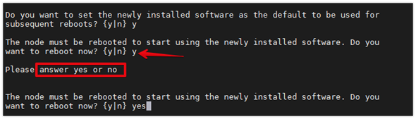
![]() During the ONTAP installation a prompt to reboot the node requests a Y/N response. The prompt requires the entire Yes or No response to reboot the node and continue the installation.
During the ONTAP installation a prompt to reboot the node requests a Y/N response. The prompt requires the entire Yes or No response to reboot the node and continue the installation.
15. Press Ctrl-C when the following message displays:
Press Ctrl-C for Boot Menu
16. Choose option 4 for Clean Configuration and Initialize All Disks.
17. Enter y to zero disks, reset config, and install a new file system.
18. Enter yes to erase all the data on the disks.
![]() The initialization and creation of the root aggregate can take 90 minutes or more to complete, depending on the number and type of disks attached. When initialization is complete, the storage system reboots. Note that SSDs take considerably less time to initialize. You can continue with the configuration of node 02 while the disks for node 01 are zeroing.
The initialization and creation of the root aggregate can take 90 minutes or more to complete, depending on the number and type of disks attached. When initialization is complete, the storage system reboots. Note that SSDs take considerably less time to initialize. You can continue with the configuration of node 02 while the disks for node 01 are zeroing.
Configure Node 02
To configure node 02, follow these steps:
1. Connect to the storage system console port. You should see a Loader-B prompt. However, if the storage system is in a reboot loop, press Ctrl-C to exit the autoboot loop when the following message displays:
Starting AUTOBOOT press Ctrl-C to abort…
2. Allow the system to boot up.
autoboot
3. Press Ctrl-C when prompted.
![]() If ONTAP 9.9.1 is not the version of software being booted, continue with the following steps to install new software. If ONTAP 9.9.1 is the version being booted, choose option 8 and y to reboot the node, then continue with step 16.
If ONTAP 9.9.1 is not the version of software being booted, continue with the following steps to install new software. If ONTAP 9.9.1 is the version being booted, choose option 8 and y to reboot the node, then continue with step 16.
4. To install new software, choose option 7.
5. Enter y to continue the installation.
6. Choose e0M for the network port you want to use for the download.
7. Enter n to skip the reboot.
8. Choose option 7: Install new software first
9. Enter y to continue the installation
10. Enter the IP address, netmask, and default gateway for e0M.
Enter the IP address for port e0M: <node02-mgmt-ip>
Enter the netmask for port e0M: <node02-mgmt-mask>
Enter the IP address of the default gateway: <node02-mgmt-gateway>
11. Enter the URL where the software can be found.
![]() The web server must be pingable from node 02.
The web server must be pingable from node 02.
<url-boot-software>
12. Press Enter for the username, indicating no user name.
13. Enter y to set the newly installed software as the default to be used for subsequent reboots.
14. Enter yes to reboot the node.
![]() When installing new software, the system might perform firmware upgrades to the BIOS and adapter cards, causing reboots and possible stops at the Loader-A prompt. If these actions occur, the system might deviate from this procedure.
When installing new software, the system might perform firmware upgrades to the BIOS and adapter cards, causing reboots and possible stops at the Loader-A prompt. If these actions occur, the system might deviate from this procedure.
![]() During the ONTAP installation a prompt to reboot the node requests a Y/N response. The prompt requires the entire Yes or No response to reboot the node and continue the installation.
During the ONTAP installation a prompt to reboot the node requests a Y/N response. The prompt requires the entire Yes or No response to reboot the node and continue the installation.
15. Press Ctrl-C when you see this message:
Press Ctrl-C for Boot Menu
16. Choose option 4 for Clean Configuration and Initialize All Disks.
17. Enter y to zero disks, reset config, and install a new file system.
18. Enter yes to erase all the data on the disks.
![]() The initialization and creation of the root aggregate can take 90 minutes or more to complete, depending on the number and type of disks attached. When initialization is complete, the storage system reboots. Note that SSDs take considerably less time to initialize.
The initialization and creation of the root aggregate can take 90 minutes or more to complete, depending on the number and type of disks attached. When initialization is complete, the storage system reboots. Note that SSDs take considerably less time to initialize.
From a console port program attached to the storage controller A (node 01) console port, run the node setup script. This script appears when ONTAP 9.9.1 boots on the node for the first time. To set up the node, follow these steps:
1. Follow the prompts to set up node 01.
Welcome to node setup.
You can enter the following commands at any time:
"help" or "?" - if you want to have a question clarified,
"back" - if you want to change previously answered questions, and
"exit" or "quit" - if you want to quit the setup wizard.
Any changes you made before quitting will be saved.
You can return to cluster setup at any time by typing “cluster setup”.
To accept a default or omit a question, do not enter a value.
This system will send event messages and weekly reports to NetApp Technical Support.
To disable this feature, enter "autosupport modify -support disable" within 24 hours.
Enabling AutoSupport can significantly speed problem determination and resolution should a problem occur on your system.
For further information on AutoSupport, see:
http://support.netapp.com/autosupport/
Type yes to confirm and continue {yes}: yes
Enter the node management interface port [e0M]: Enter
Enter the node management interface IP address: <node01-mgmt-ip>
Enter the node management interface netmask: <node01-mgmt-mask>
Enter the node management interface default gateway: <node01-mgmt-gateway>
A node management interface on port e0M with IP address <node01-mgmt-ip> has been created
Use your web browser to complete cluster setup by accesing https://<node01-mgmt-ip>
Otherwise press Enter to complete cluster setup using the command line interface:
2. To complete cluster setup, open a web browser and navigate to https://<node01-mgmt-ip>.
Table 5. Cluster Create in ONTAP Prerequisites
| Cluster Detail |
Cluster Detail Value |
| Cluster name |
<clustername> |
| Cluster Admin SVM |
<cluster-adm-svm> |
| Infrastructure Data SVM |
<infra-data-svm> |
| ONTAP base license |
<cluster-base-license-key> |
| Cluster management IP address |
<clustermgmt-ip> |
| Cluster management netmask |
<clustermgmt-mask> |
| Cluster management gateway |
<clustermgmt-gateway> |
| Cluster node 01 IP address |
<node01-mgmt-ip> |
| Cluster node 01 netmask |
<node01-mgmt-mask> |
| Cluster node 01 gateway |
<node01-mgmt-gateway> |
| Cluster node 02 IP address |
<node02-mgmt-ip> |
| Cluster node 02 netmask |
<node02-mgmt-mask> |
| Cluster node 02 gateway |
<node02-mgmt-gateway> |
| Node 01 service processor IP address |
<node01-sp-ip> |
| Node 01 service processor network mask |
<node01-sp-mask> |
| Node 01 service processor gateway |
<node01-sp-gateway> |
| Node 02 service processor IP address |
<node02-sp-ip> |
| Node 02 service processor network mask |
<node02-sp-mask> |
| Node 02 service processor gateway |
<node02-sp-gateway> |
| Node 01 node name |
<st-node01> |
| Node 02 node name |
<st-node02> |
| DNS domain name |
<dns-domain-name> |
| DNS server IP address |
<dns-ip> |
| NTP server A IP address |
<switch-a-ntp-ip> |
| NTP server B IP address |
<switch-b-ntp-ip> |
| SNMPv3 User |
<snmp-v3-usr> |
| SNMPv3 Authentication Protocol |
<snmp-v3-auth-proto> |
| SNMPv3 Privacy Protocol |
<snmpv3-priv-proto> |
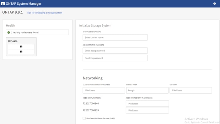
![]() Cluster setup can also be performed using the CLI. This document describes the cluster setup using the NetApp ONTAP System Manager guided setup.
Cluster setup can also be performed using the CLI. This document describes the cluster setup using the NetApp ONTAP System Manager guided setup.
3. Complete the required information on the Initialize Storage System screen:
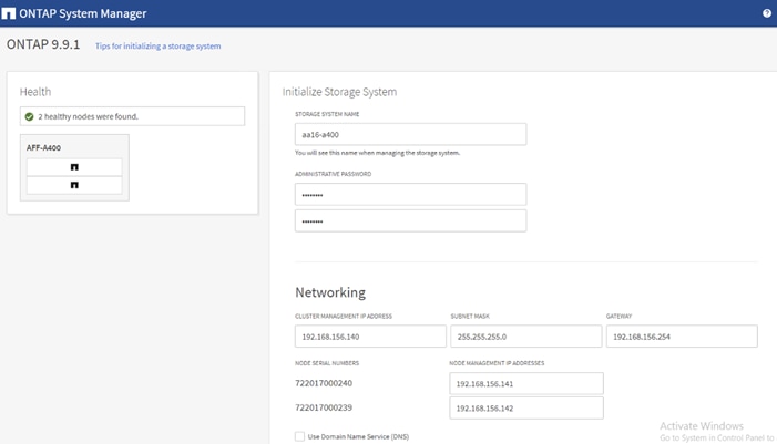
4. In the Cluster screen, follow these steps:
a. Enter the cluster name and administrator password.
b. Complete the Networking information for the cluster and each node.
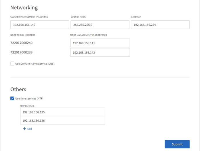
c. Check the box for Use time services (NTP) and enter the IP addresses of the time servers in a comma separated list.
![]() The nodes should be discovered automatically; if they are not, Refresh the browser page. By default, the cluster interfaces are created on all the new factory shipping storage controllers.
The nodes should be discovered automatically; if they are not, Refresh the browser page. By default, the cluster interfaces are created on all the new factory shipping storage controllers.
![]() If all the nodes are not discovered, then configure the cluster using the command line.
If all the nodes are not discovered, then configure the cluster using the command line.
![]() The node management interface can be on the same subnet as the cluster management interface, or it can be on a different subnet. In this document, we assume that it is on the same subnet.
The node management interface can be on the same subnet as the cluster management interface, or it can be on a different subnet. In this document, we assume that it is on the same subnet.
5. Click Submit.
6. A few minutes will pass while the cluster is configured. When prompted, login to ONTAP System Manager to continue the cluster configuration.
![]() You can use Ansible scripts at this point to configure the remaining part of the Storage Configurations.
You can use Ansible scripts at this point to configure the remaining part of the Storage Configurations.
7. Edit the following variable files to ensure proper ONTAP Storage variables are entered:
● FlexPod-M6/FlexPod-UCSM-M6/inventory
● FlexPod-M6/FlexPod-UCSM-M6/group_vars/all.yml
● FlexPod-M6/FlexPod-UCSM-M6/group_vars/ontap
● FlexPod-M6/FlexPod-UCSM-M6/vars/ontap_main.yml
8. From /root/ FlexPod-M6/FlexPod-UCSM-M6, run the Setup_ONTAP.yml Ansible playbook.
ansible-playbook -i inventory Setup_ONTAP.yml -t ontap_config_part_1
![]() Use the -vvv tag to see detailed execution output log.
Use the -vvv tag to see detailed execution output log.
![]() Ansible will implement all the Storage configurations tasks in this section. Skip the following steps and go to the Cisco UCS Configuration section.
Ansible will implement all the Storage configurations tasks in this section. Skip the following steps and go to the Cisco UCS Configuration section.
9. From the Dashboard click the Cluster menu on the left and choose Overview.
10. Click the More ellipsis button in the Overview pane at the top right of the screen and choose Edit.
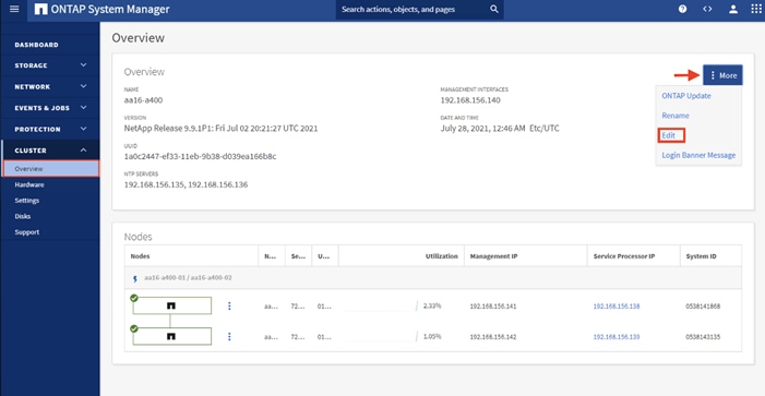
11. Add additional cluster configuration details and click Save to make the changes persistent:
a. Cluster location
b. DNS domain name
c. DNS server IP addresses
![]() DNS server IP addresses can be added individually or with a comma separated list on a single line.
DNS server IP addresses can be added individually or with a comma separated list on a single line.
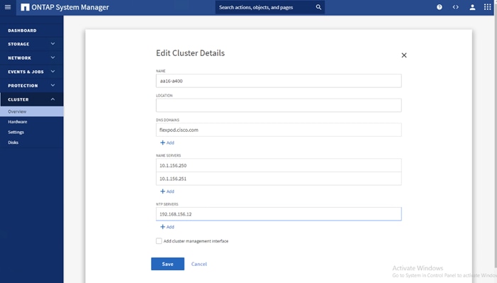
12. Click Save to make the changes persistent.
![]() To configure AutoSupport, add licenses and create storage aggregates via the ONTAP CLI, skip this section and configure the options in section Configure and Test AutoSuport.
To configure AutoSupport, add licenses and create storage aggregates via the ONTAP CLI, skip this section and configure the options in section Configure and Test AutoSuport.
13. Click the ellipsis in the top right of the AutoSupport tile and choose More options.
14. Choose the Settings menu under the Cluster menu.
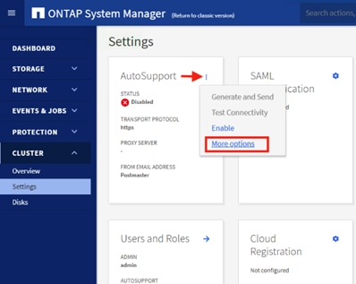
15. If AutoSupport was not configured during the initial setup, click the ellipsis in the AutoSupport tile and choose More options.
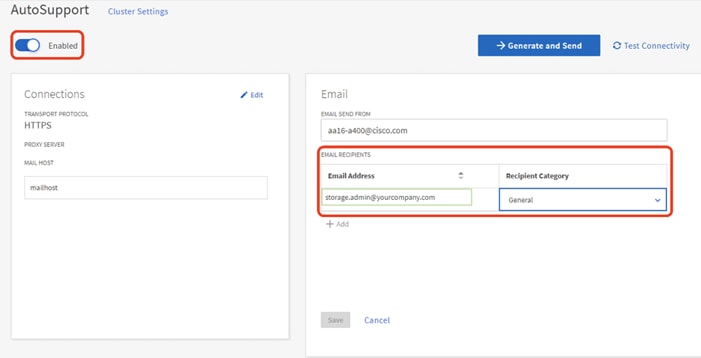
16. To enable AutoSupport click the slider.
17. Click Edit to change the transport protocol, add a proxy server address and a mail host as needed.
18. Click Save to enable the changes.
19. In the Email tile to the right, click Edit and enter the desired email information:
a. Email send from address
b. Email recipient addresses.
c. Recipient Category.
20. Click Save when complete.
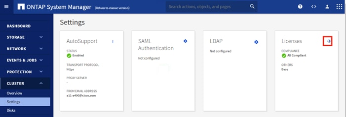
21. Choose Cluster Settings at the top left of the page to return to the cluster settings page.
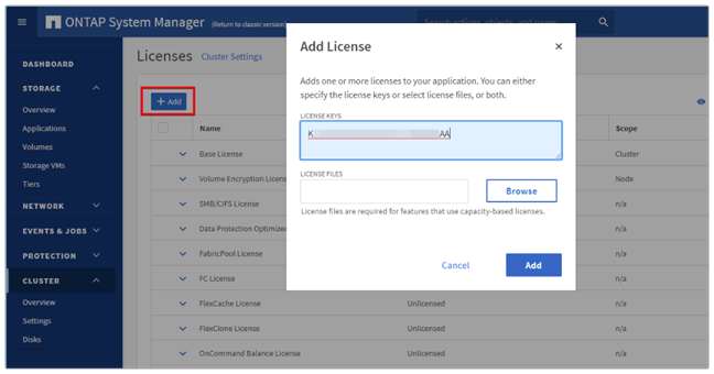
22. Locate the Licenses tile on the right and click the detail arrow.
23. Add the desired licenses to the cluster by clicking Add and entering the license keys in a comma separated list.
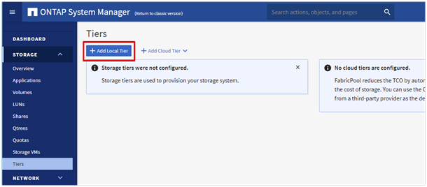
24. Configure storage aggregates by selecting the Storage menu on the left and choosing Tiers.
25. Click Add Local Tier and allow ONTAP System Manager to recommend a storage aggregate configuration.
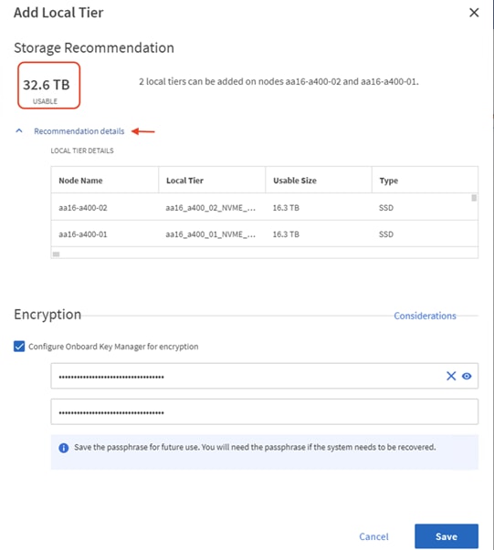
26. ONTAP will use best practices to recommend an aggregate layout. Click the Recommended details link to view the aggregate information.
27. Optionally, enable NetApp Aggregate Encryption (NAE) by checking the box for Configure Onboard Key Manager for encryption.
28. Enter and confirm the passphrase and save it in a secure location for future use.
29. Click Save to make the configuration persistent.
![]() Careful consideration should be taken before enabling aggregate encryption. Aggregate encryption may not be supported for all deployments. Please review the NetApp Encryption Power Guide and the Security Hardening Guide for NetApp ONTAP 9 (TR-4569) to help determine if aggregate encryption is right for your environment.
Careful consideration should be taken before enabling aggregate encryption. Aggregate encryption may not be supported for all deployments. Please review the NetApp Encryption Power Guide and the Security Hardening Guide for NetApp ONTAP 9 (TR-4569) to help determine if aggregate encryption is right for your environment.
To log into the cluster, follow these steps:
1. Open an SSH connection to either the cluster IP or the host name.
2. Log into the admin user with the password you provided earlier.
To confirm that storage failover is enabled, run the following commands for a failover pair:
1. Verify the status of the storage failover.
storage failover show
![]() Both <st-node01> and <st-node02> must be capable of performing a takeover. Continue with step 2 if the nodes are capable of performing a takeover.
Both <st-node01> and <st-node02> must be capable of performing a takeover. Continue with step 2 if the nodes are capable of performing a takeover.
2. Enable failover on one of the two nodes if it was not completed during the installation.
storage failover modify -node <st-node01> -enabled true
![]() Enabling failover on one node enables it for both nodes.
Enabling failover on one node enables it for both nodes.
3. Verify the HA status for a two-node cluster.
![]() This step is not applicable for clusters with more than two nodes.
This step is not applicable for clusters with more than two nodes.
cluster ha show
4. If HA is not configured use the below commands. Only enable HA mode for two-node clusters. Do not run this command for clusters with more than two nodes because it causes problems with failover.
cluster ha modify -configured true
Do you want to continue? {y|n}: y
5. Verify that hardware assist is correctly configured.
storage failover hwassist show
6. If hwassist storage failover is not enabled, enable using the following commands.
storage failover modify –hwassist-partner-ip <node02-mgmt-ip> -node <st-node01>
storage failover modify –hwassist-partner-ip <node01-mgmt-ip> -node <st-node02>
Set Auto-Revert on Cluster Management
To set the auto-revert parameter on the cluster management interface, follow this step:
![]() A storage virtual machine (SVM) is referred to as a Vserver or vserver in the GUI and CLI.
A storage virtual machine (SVM) is referred to as a Vserver or vserver in the GUI and CLI.
1. Run the following command:
net interface modify -vserver <clustername> -lif cluster_mgmt_lif_1 -auto-revert true
To zero all spare disks in the cluster, run the following command:
disk zerospares
![]() Advanced Data Partitioning creates a root partition and two data partitions on each SSD drive in an AFF configuration. Disk autoassign should have assigned one data partition to each node in an HA pair. If a different disk assignment is required, disk autoassignment must be disabled on both nodes in the HA pair by running the disk option modify command. Spare partitions can then be moved from one node to another by running the disk removeowner and disk assign commands.
Advanced Data Partitioning creates a root partition and two data partitions on each SSD drive in an AFF configuration. Disk autoassign should have assigned one data partition to each node in an HA pair. If a different disk assignment is required, disk autoassignment must be disabled on both nodes in the HA pair by running the disk option modify command. Spare partitions can then be moved from one node to another by running the disk removeowner and disk assign commands.
Set Up Service Processor Network Interface
To assign a static IPv4 address to the Service Processor on each node, run the following commands:
system service-processor network modify –node <st-node01> -address-family IPv4 –enable true –dhcp none –ip-address <node01-sp-ip> -netmask <node01-sp-mask> -gateway <node01-sp-gateway>
system service-processor network modify –node <st-node02> -address-family IPv4 –enable true –dhcp none –ip-address <node02-sp-ip> -netmask <node02-sp-mask> -gateway <node02-sp-gateway>
![]() The Service Processor IP addresses should be in the same subnet as the node management IP addresses.
The Service Processor IP addresses should be in the same subnet as the node management IP addresses.
Create Manual Provisioned Aggregates (Optional)
An aggregate containing the root volume is created during the ONTAP setup process. To manually create additional aggregates, determine the aggregate name, the node on which to create it, and the number of disks it should contain.
To create new aggregates, run the following commands:
storage aggregate create -aggregate <aggr1_node01> -node <st-node01> -diskcount <num-disks> -disktype SSD-NVM
storage aggregate create -aggregate <aggr1_node02> -node <st-node02> -diskcount <num-disks> -disktype SSD-NVM
![]() You should have the minimum number of hot spare disks for hot spare disk partitions recommended for your aggregate.
You should have the minimum number of hot spare disks for hot spare disk partitions recommended for your aggregate.
![]() For all-flash aggregates, you should have a minimum of one hot spare disk or disk partition. For non-flash homogenous aggregates, you should have a minimum of two hot spare disks or disk partitions. For Flash Pool aggregates, you should have a minimum of two hot spare disks or disk partitions for each disk type.
For all-flash aggregates, you should have a minimum of one hot spare disk or disk partition. For non-flash homogenous aggregates, you should have a minimum of two hot spare disks or disk partitions. For Flash Pool aggregates, you should have a minimum of two hot spare disks or disk partitions for each disk type.
![]() In an AFF configuration with a small number of SSDs, you might want to create an aggregate with all but one remaining disk (spare) assigned to the controller.
In an AFF configuration with a small number of SSDs, you might want to create an aggregate with all but one remaining disk (spare) assigned to the controller.
![]() The aggregate cannot be created until disk zeroing completes. Run the storage aggregate show command to display the aggregate creation status. Do not proceed until both aggr1_node1 and aggr1_node2 are online.
The aggregate cannot be created until disk zeroing completes. Run the storage aggregate show command to display the aggregate creation status. Do not proceed until both aggr1_node1 and aggr1_node2 are online.
Remove Default Broadcast Domains
By default, all network ports are included in separate default broadcast domain. Network ports used for data services (for example, e0e, e0f, and so on) should be removed from their default broadcast domain and that broadcast domain should be deleted.
To perform this task, run the following commands:
network port broadcast-domain delete -broadcast-domain <Default-N> -ipspace Default
network port broadcast-domain show
Disable Flow Control on 25/100GbE Data Ports
To disable flow control on 25 and 100GbE data ports, follow these steps:
1. Run the following command to configure the ports .on node 01:
network port modify -node <st-node01> -port e4a,e4b -flowcontrol-admin none network port modify -node <st-node01> -port e0e,e0f,e0g,e0h -flowcontrol-admin none
2. Run the following command to configure the ports on node 02:
network port modify -node <st-node02> -port e4a,e4b -flowcontrol-admin none
network port modify -node <st-node02> -port e0e,e0f,e0g,e0h -flowcontrol-admin none
aa16-a400::> net port show -node * -port e0e,e0f,e0g,e0h -fields speed-admin,duplex-admin,flowcontrol-admin
(network port show)
node port duplex-admin speed-admin flowcontrol-admin
------------ ---- ------------ ----------- -----------------
aa16-a400-01 e0e auto auto none
aa16-a400-01 e0f auto auto none
aa16-a400-01 e0g auto auto none
aa16-a400-01 e0h auto auto none
aa16-a400-02 e0e auto auto none
aa16-a400-02 e0f auto auto none
aa16-a400-02 e0g auto auto none
aa16-a400-02 e0h auto auto none
8 entries were displayed.
aa16-a400::> net port show -node * -port e4a,e4b -fields speed-admin,duplex-admin,flowcontrol-admin
(network port show)
node port duplex-admin speed-admin flowcontrol-admin
------------ ---- ------------ ----------- -----------------
aa16-a400-01 e4a auto auto none
aa16-a400-01 e4b auto auto none
aa16-a400-02 e4a auto auto none
aa16-a400-02 e4b auto auto none
4 entries were displayed.
Disable Auto-Negotiate on Fibre Channel Ports
In accordance with the best practices for FC host ports, to disable auto-negotiate on each FCP adapter in each controller node, follow these steps:
1. Disable each FC adapter in the controllers with the fcp adapter modify command.
fcp adapter modify -node <st-node01> -adapter 5a –status-admin down
fcp adapter modify -node <st-node01> -adapter 5b –status-admin down
fcp adapter modify -node <st-node02> -adapter 5a –status-admin down
fcp adapter modify -node <st-node02> -adapter 5b –status-admin down
2. Set the desired speed on the adapter and return it to the online state.
fcp adapter modify -node <st-node01> -adapter 5a -speed 32 -status-admin up
fcp adapter modify -node <st-node01> -adapter 5b -speed 32 -status-admin up
fcp adapter modify -node <st-node02> -adapter 5a -speed 32 -status-admin up
fcp adapter modify -node <st-node02> -adapter 5b -speed 32 -status-admin up
Enable Cisco Discovery Protocol
To enable the Cisco Discovery Protocol (CDP) on the NetApp storage controllers, run the following command to enable CDP in ONTAP:
node run -node * options cdpd.enable on
![]() To be effective, CDP must also be enabled on directly connected networking equipment such as switches and routers.
To be effective, CDP must also be enabled on directly connected networking equipment such as switches and routers.
Enable Link-layer Discovery Protocol on all Ethernet Ports
To enable the exchange of Link-layer Discovery Protocol (LLDP) neighbor information between the storage and network switches, follow this step:
1. Enable LLDP on all ports of all nodes in the cluster.
node run * options lldp.enable on
Create Management Broadcast Domain
If the management interfaces are required to be on a separate VLAN, create a new broadcast domain for those interfaces by running the following command:
network port broadcast-domain create -broadcast-domain IB-MGMT -mtu 1500
network port broadcast-domain show
To create an NFS data broadcast domain with a maximum transmission unit (MTU) of 9000, run the following commands to create a broadcast domain for NFS in ONTAP:
network port broadcast-domain create -broadcast-domain Infra_NFS -mtu 9000
network port broadcast-domain show
To create the LACP interface groups for the 25GbE data interfaces, run the following commands:
network port ifgrp create -node <st-node01> -ifgrp a0a -distr-func port -mode multimode_lacp
network port ifgrp add-port -node <st-node01> -ifgrp a0a -port e0e
network port ifgrp add-port -node <st-node01> -ifgrp a0a -port e0f
network port ifgrp add-port -node <st-node01> -ifgrp a0a -port e0g
network port ifgrp add-port -node <st-node01> -ifgrp a0a -port e0h
network port ifgrp create -node <st-node02> -ifgrp a0a -distr-func port -mode multimode_lacp
network port ifgrp add-port -node <st-node02> -ifgrp a0a -port e0e
network port ifgrp add-port -node <st-node02> -ifgrp a0a -port e0f
network port ifgrp add-port -node <st-node02> -ifgrp a0a -port e0g
network port ifgrp add-port -node <st-node02> -ifgrp a0a -port e0h
network port ifgrp show
Change MTU on Interface Groups
To change the MTU size on the base interface-group ports before creating the VLAN ports, run the following commands:
network port modify –node <st-node01> -port a0a –mtu 9000
network port modify –node <st-node02> -port a0a –mtu 9000
To create VLANs, follow these steps:
1. Create the management VLAN ports and add them to the management broadcast domain.
network port vlan create –node <st-node01> -vlan-name a0a-<ib-mgmt-vlan-id>
network port vlan create –node <st-node02> -vlan-name a0a-<ib-mgmt-vlan-id>
network port broadcast-domain add-ports -broadcast-domain IB-MGMT -ports <st-node01>:a0a-<ib-mgmt-vlan-id>,<st-node02>:a0a-<ib-mgmt-vlan-id>
network port vlan show
2. Create the NFS VLAN ports and add them to the Infra_NFS broadcast domain.
network port vlan create –node <st-node01> -vlan-name a0a-<infra-nfs-vlan-id>
network port vlan create –node <st-node02> -vlan-name a0a-<infra-nfs-vlan-id>
network port broadcast-domain add-ports -broadcast-domain Infra_NFS -ports <st-node01>:a0a-<infra-nfs-vlan-id>,<st-node02>:a0a-<infra-nfs-vlan-id>
Configure Network Time Protocol
To configure time synchronization on the cluster, follow these steps:
1. Set the time zone for the cluster.
timezone -timezone <timezone>
![]() For example, in the eastern United States, the time zone is America/New_York.
For example, in the eastern United States, the time zone is America/New_York.
2. Set the date for the cluster.
date <ccyymmddhhmm.ss>
![]() The format for the date is <[Century][Year][Month][Day][Hour][Minute].[Second]> (for example, 201903271549.30).
The format for the date is <[Century][Year][Month][Day][Hour][Minute].[Second]> (for example, 201903271549.30).
Configure Simple Network Management Protocol
To configure the Simple Network Management Protocol (SNMP), follow these steps:
1. Configure basic SNMP information, such as the location and contact. When polled, this information is visible as the sysLocation and sysContact variables in SNMP.
snmp contact <snmp-contact>
snmp location “<snmp-location>”
snmp init 1
options snmp.enable on
2. Configure SNMP traps to send to remote hosts, such as an Active IQ Unified Manager server or another fault management system.
snmp traphost add <oncommand-um-server-fqdn>
SNMPv3 offers advanced security by using encryption and passphrases. The SNMPv3 user can run SNMP utilities from the traphost using the authentication and privacy settings that you specify. To configure SNMPv3 access, run the following commands:
security login create -user-or-group-name <<snmp-v3-usr>> -application snmp -authentication-method usm
Enter the authoritative entity's EngineID [local EngineID]:
Which authentication protocol do you want to choose (none, md5, sha, sha2-256) [none]: <<snmp-v3-auth-proto>>
Enter the authentication protocol password (minimum 8 characters long):
Enter the authentication protocol password again:
Which privacy protocol do you want to choose (none, des, aes128) [none]: <<snmpv3-priv-proto>>
Enter privacy protocol password (minimum 8 characters long):
Enter privacy protocol password again:
![]() Refer to the SNMP Configuration Express Guide for additional information when configuring SNMPv3 security users.
Refer to the SNMP Configuration Express Guide for additional information when configuring SNMPv3 security users.
Create SVM
To create an infrastructure SVM, follow these steps:
1. Run the vserver create command.
vserver create –vserver Infra-SVM –rootvolume infra_svm_root –aggregate aggr1_node01 –rootvolume-security-style unix
2. Remove the unused data protocols from the SVM: CIFS, iSCSI.
vserver remove-protocols –vserver Infra-SVM -protocols iscsi,cifs
3. Add the two data aggregates to the Infra-SVM aggregate list for the NetApp ONTAP Tools.
vserver modify –vserver Infra-SVM –aggr-list <aggr1_node01>,<aggr1_node02>
4. Enable and run the NFS protocol in the Infra-SVM.
vserver nfs create -vserver Infra-SVM -udp disabled -v3 enabled -v4.1 enabled -vstorage enabled
![]() If the NFS license was not installed during the cluster configuration, make sure to install the license before starting the NFS service.
If the NFS license was not installed during the cluster configuration, make sure to install the license before starting the NFS service.
5. Verify the NFS vstorage parameter for the NetApp NFS VAAI plug-in was enabled.
vserver nfs show -fields vstorage
Create Load-Sharing Mirrors of SVM Root Volume
To create a load-sharing mirror of an SVM root volume, follow these steps:
1. Create a volume to be the load-sharing mirror of the infrastructure SVM root volume on each node.
volume create –vserver Infra-SVM –volume infra_svm_root_m01 –aggregate <aggr1_node01> –size 1GB –type DP
volume create –vserver Infra-SVM –volume infra_svm_root_m02 –aggregate <aggr1_node02> –size 1GB –type DP
2. Create a job schedule to update the root volume mirror relationships every 15 minutes.
job schedule interval create -name 15min -minutes 15
3. Create the mirroring relationships.
snapmirror create –source-path Infra-SVM:infra_svm_root -destination-path Infra-SVM:infra_svm_root_m01 –type LS -schedule 15min
snapmirror create –source-path Infra-SVM:infra_svm_root –destination-path Infra-SVM:infra_svm_root_m02 –type LS -schedule 15min
4. Initialize the mirroring relationship.
snapmirror initialize-ls-set –source-path Infra-SVM:infra_svm_root
snapmirror show -type ls
Create Block Protocol (FC) Service
Run the following command to create the FCP service on each SVM. This command also starts the FCP service and sets the worldwide name (WWN) for the SVM:
vserver fcp create -vserver Infra-SVM -status-admin up
vserver fcp show
![]() If the FC license was not installed during the cluster configuration, make sure to install the license before creating the FC service.
If the FC license was not installed during the cluster configuration, make sure to install the license before creating the FC service.
To configure secure access to the storage controller, follow these steps:
1. Increase the privilege level to access the certificate commands.
set -privilege diag
Do you want to continue? {y|n}: y
2. Generally, a self-signed certificate is already in place. Verify the certificate and obtain parameters (for example, the <serial-number>) by running the following command:
security certificate show
3. For each SVM shown, the certificate common name should match the DNS fully qualified domain name (FQDN) of the SVM. Delete the two default certificates and replace them with either self-signed certificates or certificates from a certificate authority (CA). To delete the default certificates, run the following commands:
security certificate delete -vserver Infra-SVM -common-name Infra-SVM -ca Infra-SVM -type server -serial <serial-number>
![]() Deleting expired certificates before creating new certificates is a best practice. Run the security certificate delete command to delete the expired certificates. In the following command, use TAB completion to select and delete each default certificate.
Deleting expired certificates before creating new certificates is a best practice. Run the security certificate delete command to delete the expired certificates. In the following command, use TAB completion to select and delete each default certificate.
4. To generate and install self-signed certificates, run the following commands as one-time commands. Generate a server certificate for the Infra-SVM and the cluster SVM. Use TAB completion to aid in the completion of these commands.
security certificate create -common-name <cert-common-name> -type server -size 2048 -country <cert-country> -state <cert-state> -locality <cert-locality> -organization <cert-org> -unit <cert-unit> -email-addr <cert-email> -expire-days <cert-days> -protocol SSL -hash-function SHA256 -vserver Infra-SVM
5. To obtain the values for the parameters required in step 5 (<cert-ca> and <cert-serial>), run the security certificate show command.
6. Enable each certificate that was just created by using the –server-enabled true and –client-enabled false parameters. Use TAB completion to aid in the completion of these commands.
security ssl modify -vserver <clustername> -server-enabled true -client-enabled false -ca <cert-ca> -serial <cert-serial> -common-name <cert-common-name>
7. Disable HTTP cluster management access.
system services firewall policy delete -policy mgmt -service http –vserver <clustername>
![]() It is normal for some of these commands to return an error message stating that the entry does not exist.
It is normal for some of these commands to return an error message stating that the entry does not exist.
8. Change back to the normal admin privilege level and verify that the system logs are available in a web browser.
set –privilege admin
https://<node01-mgmt-ip>/spi
https://<node02-mgmt-ip>/spi
Configure NFSv3 and NFSv4.1
To configure NFS on the SVM, follow these steps:
1. Create a new rule for the infrastructure NFS subnet in the default export policy.
vserver export-policy rule create –vserver Infra-SVM -policyname default –ruleindex 1 –protocol nfs -clientmatch <infra-nfs-subnet-cidr> -rorule sys –rwrule sys -superuser sys –allow-suid true
2. Assign the FlexPod export policy to the infrastructure SVM root volume.
volume modify –vserver Infra-SVM –volume infra_svm_root –policy default
The following information is required to create a NetApp FlexVol® volume:
● The volume name
● The volume size
● The aggregate on which the volume exists
To create a FlexVol volume, run the following commands:
volume create -vserver Infra-SVM -volume infra_datastore_01 -aggregate <aggr1_node01> -size 1TB -state online -policy default -junction-path /infra_datastore_01 -space-guarantee none -percent-snapshot-space 0
volume create -vserver Infra-SVM -volume infra_datastore_02 -aggregate <aggr1_node02> -size 1TB -state online -policy default -junction-path /infra_datastore_02 -space-guarantee none -percent-snapshot-space 0
volume create -vserver Infra-SVM -volume infra_swap -aggregate <aggr1_node01> -size 100GB -state online -policy default -junction-path /infra_swap -space-guarantee none -percent-snapshot-space 0 -snapshot-policy none.
volume create -vserver Infra-SVM -volume esxi_boot -aggregate <aggr1_node01> -size 320GB -state online -policy default -space-guarantee none -percent-snapshot-space 0
snapmirror update-ls-set -source-path Infra-SVM:infra_svm_root
![]() If you are going to setup and use SnapCenter to backup the infra_datastore volume, add “-snapshot-policy none” to the end of the volume create command for the infra_datastore volume.
If you are going to setup and use SnapCenter to backup the infra_datastore volume, add “-snapshot-policy none” to the end of the volume create command for the infra_datastore volume.
On NetApp AFF systems, deduplication is enabled by default. To disable the efficiency policy on the infra_swap volume, run the following command:
volume efficiency off –vserver Infra-SVM –volume infra_swap
Run the following commands to create four FC LIFs (two on each node):
network interface create -vserver Infra-SVM -lif fcp-lif-01a -role data -data-protocol fcp -home-node <st-node01> -home-port 5a –status-admin up
network interface create -vserver Infra-SVM -lif fcp-lif-01b -role data -data-protocol fcp -home-node <st-node01> -home-port 5b –status-admin up
network interface create -vserver Infra-SVM -lif fcp-lif-02a -role data -data-protocol fcp -home-node <st-node02> -home-port 5a –status-admin up
network interface create -vserver Infra-SVM -lif fcp-lif-02b -role data -data-protocol fcp -home-node <st-node02> -home-port 5b –status-admin up
network interface show
To create NFS LIFs, run the following commands:
network interface create -vserver Infra-SVM -lif nfs-lif-01 -role data -data-protocol nfs -home-node <st-node01> -home-port a0a-<infra-nfs-vlan-id> –address <node01-nfs-lif-01-ip> -netmask <node01-nfs-lif-01-mask> -status-admin up –failover-policy broadcast-domain-wide –firewall-policy data –auto-revert true
network interface create -vserver Infra-SVM -lif nfs-lif-02 -role data -data-protocol nfs -home-node <st-node02> -home-port a0a-<infra-nfs-vlan-id> –address <node02-nfs-lif-02-ip> -netmask <node02-nfs-lif-02-mask>> -status-admin up –failover-policy broadcast-domain-wide –firewall-policy data –auto-revert true
network interface show
Configure FC-NVMe Datastore for vSphere 7U2
To Configure FC-NVMe Datastores for vSphere 7U2 enable the FC-NVMe protocol on an existing SVM or create a separate SVM for FC-NVMe workloads.
To configure FC-NVMe datastore on existing SVM (Infra-SVM) follow these steps:
1. Verify that you have NVMe Capable adapters installed in your cluster.
network fcp adapter show -data-protocols-supported fc-nvme
2. Add the NVMe protocol to the SVM and list it.
vserver add-protocols -vserver Infra-SVM -protocols nvme
vserver show -vserver Infra-SVM -fields allowed-protocols
aa16-a400::> vserver show -vserver Infra-SVM -fields allowed-protocols
vserver allowed-protocols
--------- -----------------------
Infra-SVM nfs,fcp,iscsi,ndmp,nvme
3. Create NVMe service.
vserver nvme create -vserver Infra-SVM
vserver nvme show -vserver Infra-SVM
aa16-a400::> vserver nvme show -vserver Infra-SVM
Vserver Name: Infra-SVM
Administrative Status: up
4. Create NVMe FC LIFs.
network interface create -vserver <SVM_name> -lif <lif_name> -role data -data-protocol fc-nvme -home-node <home_node> -home-port <home_portnetwork>
network interface create -vserver Infra-SVM -lif fc-nvme-lif-01a -role data -data-protocol fc-nvme -home-node <st-node01> -home-port 5a –status-admin up
network interface create -vserver Infra-SVM -lif fc-nvme-lif-01b -role data -data-protocol fc-nvme -home-node <st-node01> -home-port 5b –status-admin up
network interface create -vserver Infra-SVM -lif fcp-nvme-lif-02a -role data -data-protocol fc-nvme -home-node <st-node02> -home-port 5a –status-admin up
network interface create -vserver Infra-SVM -lif fcp-nvme-lif-02b -role data -data-protocol fc-nvme -home-node <st-node02> -home-port 5b –status-admin up
network interface show
![]() You can only configure two NVMe LIFs per node on a maximum of four nodes.
You can only configure two NVMe LIFs per node on a maximum of four nodes.
net int show -vserver <vserver name> -data-protocol fc-nvme
aa16-a400::> net int show -vserver Infra-SVM -data-protocol fc-nvme
(network interface show)
Logical Status Network Current Current Is
Vserver Interface Admin/Oper Address/Mask Node Port Home
----------- ---------- ---------- ------------------ ------------- ------- ----
Infra-SVM
fc-nvme-lif-01a
up/up 20:0f:d0:39:ea:17:12:9b
aa16-a400-01 5a true
fc-nvme-lif-01b
up/up 20:10:d0:39:ea:17:12:9b
aa16-a400-01 5b true
fcp-nvme-lif-02a
up/up 20:11:d0:39:ea:17:12:9b
aa16-a400-02 5a true
fcp-nvme-lif-02b
up/up 20:12:d0:39:ea:17:12:9b
aa16-a400-02 5b true
4 entries were displayed.
5. Create Volume
Volume create -vserver SVM-name -volume vol_name -aggregate aggregate_name -size volume_size -space-guarantee none -percent-snapshot-space 0
aa16-a400::> vol create -vserver Infra-SVM -volume NVMe_datastore_01 -aggregate aa16_a400_01_NVME_SSD_1 -size 100G -state online -space-guarantee none -percent-snapshot-space 0
[Job 162] Job succeeded: Successful
Add Infrastructure SVM Administrator
To add the infrastructure SVM administrator and SVM administration LIF in the in-band management network, follow these steps:
1. Run the following commands:
network interface create –vserver Infra-SVM –lif svm-mgmt –role data –data-protocol none –home-node <st-node02> -home-port a0a-<ib-mgmt-vlan-id> –address <svm-mgmt-ip> -netmask <svm-mgmt-mask> -status-admin up –failover-policy broadcast-domain-wide –firewall-policy mgmt –auto-revert true
2. Create a default route that enables the SVM management interface to reach the outside world.
network route create –vserver Infra-SVM -destination 0.0.0.0/0 –gateway <svm-mgmt-gateway>
network route show
3. Set a password for the SVM vsadmin user and unlock the user.
security login password –username vsadmin –vserver Infra-SVM
Enter a new password: <password>
Enter it again: <password>
security login unlock –username vsadmin –vserver Infra-SVM
![]() A cluster serves data through at least one and possibly several SVMs. These steps have created a single data SVM. If you would like to configure your environment with multiple SVMs, this is a good time to create them.
A cluster serves data through at least one and possibly several SVMs. These steps have created a single data SVM. If you would like to configure your environment with multiple SVMs, this is a good time to create them.
Configure AutoSupport
NetApp AutoSupport® sends support summary information to NetApp through HTTPS. To configure AutoSupport, run the following command:
system node autosupport modify -node * -state enable –mail-hosts <mailhost> -transport https -support enable -noteto <storage-admin-email>
Cisco Intersight-based Cisco UCS Infrastructure Upgrade
Cisco Intersight can be used to upgrade Cisco UCS Managed Infrastructure. This procedure demonstrates an Intersight-based upgrade of a Cisco UCS Infrastructure (Cisco UCS Manager, fabric interconnects, and IOM modules) from software release 4.2(1f) to 4.2(1i).
If you do not already have a Cisco Intersight account, to claim your Cisco UCS into a new account on Cisco Intersight, connect to https://intersight.com. If you have an existing Intersight account, connect to https://intersight.com and sign in with your Cisco ID, select the appropriate account, and skip to step 6.
To upgrade Cisco UCS infrastructure using Cisco Intersight, follow these steps:
1. Click Create an account.
2. Sign-in with your Cisco ID.
3. Read, scroll through and accept the End User License Agreement and click Next.
4. Enter an Account Name and click Create.
5. Choose ADMIN > Targets. Click Claim Target. Select Cisco UCS Domain (UCSM Managed) and click Start. Fill in the Device ID and Claim Code and click Claim. The Device ID and Claim Code can be obtained by connecting to Cisco UCS Manager and selecting Admin > All > Device Connector. The Device ID and Claim Code are on the right.
6. To claim your Cisco UCS system into an existing Intersight account, log into the account at https://Intersight.com. Choose Administration > Devices. Click Claim a New Device. Under Direct Claim, fill in the Device ID and Claim Code and click Claim. The Device ID and Claim Code can be obtained by connecting to Cisco UCS Manager and selecting Admin > All > Device Connector. The Device ID and Claim Code are on the right.
7. From the Cisco Intersight window, click ![]() and then click Licensing. If this is a new account, all servers connected to the UCS Domain will appear under the Base license Tier. If you have purchased Cisco Intersight licenses and have them in your Cisco Smart Account, click Register and follow the prompts to register this Cisco Intersight account to your Cisco Smart Account. Cisco Intersight also offers a one-time 90-day trial of Premier licensing for new accounts. Click Start Trial and then Start to begin this evaluation. The remainder of this section will assume Premier licensing.
and then click Licensing. If this is a new account, all servers connected to the UCS Domain will appear under the Base license Tier. If you have purchased Cisco Intersight licenses and have them in your Cisco Smart Account, click Register and follow the prompts to register this Cisco Intersight account to your Cisco Smart Account. Cisco Intersight also offers a one-time 90-day trial of Premier licensing for new accounts. Click Start Trial and then Start to begin this evaluation. The remainder of this section will assume Premier licensing.
8. From the Licensing Window, click Set Default Tier. From the drop-down list choose Premier for Tier and click Set.
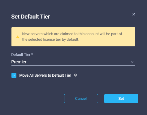
9. Click Refresh to refresh the Intersight window with Premier, Advantage, and Essentials features added.
10. To start the upgrade, select OPERATE > Fabric Interconnects. To the right of one of the fabric interconnects that you want to upgrade, click … and select Upgrade Firmware.
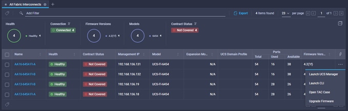
11. Click Start.
12. Ensure the UCS Domain you want to upgrade is shown and selected and click Next.
![]()
![]()
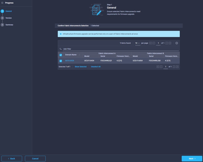
13. Choose Version 4.2(1i) and click Next.
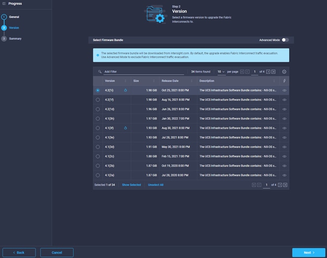
14. Click Upgrade then click Upgrade again to bring up the window allowing you to log in to retrieve software.
![]()
![]()
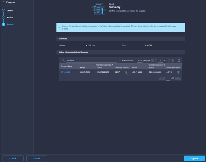
![]() It may be necessary to click Upgrade again to bring up the window allowing you to log in to retrieve software. Login with Cisco ID and password and click Submit.
It may be necessary to click Upgrade again to bring up the window allowing you to log in to retrieve software. Login with Cisco ID and password and click Submit.
15. Click Requests, then click the Upgrade Firmware request.
![]()
![]()

16. While the Cisco UCS Manager and the subordinate fabric interconnect are in the process of upgrading, click Proceed and then click Proceed again to continue the upgrade. This process will be required two times.
![]()
![]()
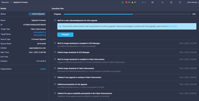
17. When the upgrade completes, the Status will show Success. You will need to copy the B-Series and C-Series update bundles to the fabric interconnects. If this upgrade is from before UCS 4.1(1), M6 servers can now be inserted in the chassis or attached to the FIs. Other servers will be upgraded by the Host Firmware Package setting.
![]()
![]()
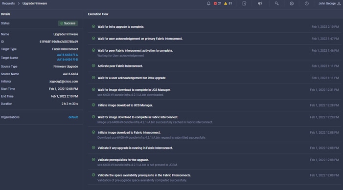
Cisco UCS Base Configuration
This FlexPod deployment explains the configuration steps for the Cisco UCS 6454 Fabric Interconnects (FI) in a design that will support FC SAN boot. The same base configuration should be done whether you are performing an automated or manual configuration.
![]() If setting up a system with iSCSI boot, the sections with (FCP) in the heading can be skipped and then complete the Cisco UCS iSCSI Configuration section in the Appendix.
If setting up a system with iSCSI boot, the sections with (FCP) in the heading can be skipped and then complete the Cisco UCS iSCSI Configuration section in the Appendix.
Perform Initial Setup of Cisco UCS 6454 Fabric Interconnects for FlexPod Environments
This section provides the detailed procedures for configuring the Cisco Unified Computing System (Cisco UCS) for use in a FlexPod environment. The steps are necessary to provision the Cisco UCS B-Series and C-Series servers and should be followed precisely to avoid improper configuration.
Cisco UCS Fabric Interconnect A
To configure the Cisco UCS for use in a FlexPod environment in ucsm managed mode, follow these steps:
1. Connect to the console port on the first Cisco UCS fabric interconnect.
Enter the configuration method. (console/gui) ? console
Enter the management mode. (ucsm/intersight)? ucsm
Enter the setup mode; setup newly or restore from backup. (setup/restore) ? setup
You have chosen to setup a new Fabric interconnect in “ucsm” managed mode. Continue? (y/n): y
Enforce strong password? (y/n) [y]: Enter
Enter the password for "admin": <password>
Confirm the password for "admin": <password>
Is this Fabric interconnect part of a cluster(select 'no' for standalone)? (yes/no) [n]: y
Enter the switch fabric (A/B) []: A
Enter the system name: <ucs-cluster-name>
Physical Switch Mgmt0 IP address : <ucsa-mgmt-ip>
Physical Switch Mgmt0 IPv4 netmask : <ucsa-mgmt-mask>
IPv4 address of the default gateway : <ucsa-mgmt-gateway>
Cluster IPv4 address : <ucs-cluster-ip>
Configure the DNS Server IP address? (yes/no) [n]: y
DNS IP address : <dns-server-1-ip>
Configure the default domain name? (yes/no) [n]: y
Default domain name : <ad-dns-domain-name>
Join centralized management environment (UCS Central)? (yes/no) [n]: Enter
Apply and save the configuration (select 'no' if you want to re-enter)? (yes/no): yes
2. Wait for the login prompt for UCS Fabric Interconnect A before proceeding to the next section.
Cisco UCS Fabric Interconnect B
To configure the Cisco UCS for use in a FlexPod environment, follow these steps:
1. Connect to the console port on the second Cisco UCS fabric interconnect.
Enter the configuration method. (console/gui) ? console
Installer has detected the presence of a peer Fabric interconnect. This Fabric interconnect will be added to the cluster. Continue (y/n) ? y
Enter the admin password of the peer Fabric interconnect: <password>
Connecting to peer Fabric interconnect... done
Retrieving config from peer Fabric interconnect... done
Peer Fabric interconnect Mgmt0 IPv4 Address: <ucsa-mgmt-ip>
Peer Fabric interconnect Mgmt0 IPv4 Netmask: <ucsa-mgmt-mask>
Cluster IPv4 address : <ucs-cluster-ip>
Peer FI is IPv4 Cluster enabled. Please Provide Local Fabric Interconnect Mgmt0 IPv4 Address
Physical Switch Mgmt0 IP address : <ucsb-mgmt-ip>
Local fabric interconnect model(UCS-FI-6454)
Peer fabric interconnect is compatible with the local fabric interconnect. Continuing with the installer...
Apply and save the configuration (select 'no' if you want to re-enter)? (yes/no): yes
2. Wait for the login prompt for UCS Fabric Interconnect B before proceeding to the next section.
Cisco UCS Setup
To log into the Cisco Unified Computing System (Cisco UCS) environment, follow these steps:
1. Open a web browser and navigate to the Cisco UCS fabric interconnect cluster address.
![]() You may need to wait at least 5 minutes after configuring the second fabric interconnect for Cisco UCS Manager to open.
You may need to wait at least 5 minutes after configuring the second fabric interconnect for Cisco UCS Manager to open.
2. Click the Launch UCS Manager link to launch Cisco UCS Manager.
3. If prompted to accept security certificates, accept as necessary.
4. When prompted, enter admin as the user name and enter the administrative password.
5. Click Login to log into Cisco UCS Manager.
To enable anonymous reporting, follow this step:
1. In the Anonymous Reporting window, choose whether to send anonymous data to Cisco for improving future products. If you choose Yes, enter the IP address of your SMTP Server. Click OK.
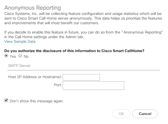
Upgrade Cisco UCS Manager Software to Version 4.2(1f)
This document assumes the use of Cisco UCS 4.2(1f). If you have not already upgraded, to upgrade the Cisco UCS Manager software and the Cisco UCS Fabric Interconnect software to version 4.2(1f), refer to Cisco UCS Manager Install and Upgrade Guides.
If you used Cisco Intersight to upgrade to 4.2(1f), the Cisco UCS B and C-Series 4.2(1f) bundles need to be manually downloaded to the Cisco UCS system.
It is highly recommended by Cisco to configure Call Home in Cisco UCS Manager. Configuring Call Home will accelerate the resolution of support cases. To configure Call Home, follow these steps:
1. In Cisco UCS Manager, click Admin.
2. Choose All > Communication Management > Call Home.
3. Change the State to On.
4. Fill in all the fields according to your Management preferences and click Save Changes and OK to complete configuring Call Home.
If you are configuring Fibre Channel in your configuration, complete this section. Fibre Channel port configurations differ between the Cisco UCS 6454, 6332-16UP and the 6248UP fabric interconnects. All fabric interconnects have a slider mechanism within the Cisco UCS Manager GUI interface, but the fibre channel port selection options for the 6454 are from the first 16 ports starting from the first port and configured in increments of 4 ports from the left. For the 6332-16UP the port selection options are from the first 16 ports starting from the first port, and configured in increments of the first 6, 12, or all 16 of the unified ports. With the 6248UP, the port selection options will start from the right of the 32 fixed ports, or the right of the 16 ports of the expansion module, going down in contiguous increments of 2. The remainder of this section shows configuration of the 6454. Modify as necessary for the 6332-16UP or 6248UP.
To enable the fibre channel ports, follow these steps for the Cisco UCS 6454:
1. In Cisco UCS Manager, click Equipment.
2. Choose Equipment > Fabric Interconnects > Fabric Interconnect B (subordinate).
3. Choose Configure Unified Ports.
4. Click Yes on the pop-up window warning that changes to the fixed module will require a reboot of the fabric interconnect and changes to the expansion module will require a reboot of that module.
5. Within the Configured Fixed Ports pop-up window move the gray slider bar from the left to the right to choose either 4, 8, 12, or 16 ports to be set as FC Uplinks.
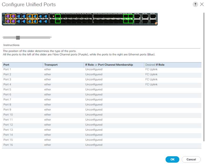
6. Click OK, then click Yes, then click OK to continue.
7. Choose Equipment > Fabric Interconnects > Fabric Interconnect A (primary).
8. Choose Configure Unified Ports.
9. Click Yes on the pop-up window warning that changes to the fixed module will require a reboot of the fabric interconnect and changes to the expansion module will require a reboot of that module.
10. Within the Configured Fixed Ports pop-up window move the gray slider bar from the left to the right to choose either 4 or 8 ports to be set as FC Uplinks.
11. Click OK, then click Yes, then OK to continue.
12. Wait for both Fabric Interconnects to reboot.
13. Log back into Cisco UCS Manager.
Ansible Cisco UCS Configuration
To configure the Cisco UCS from the Ansible management workstation, follow these steps:
1. Edit the following variable files to ensure proper Nexus variables are entered:
● FlexPod-M6/FlexPod-UCSM-M6/inventory
● FlexPod-M6/FlexPod-UCSM-M6/group_vars/all.yml
● FlexPod-M6/FlexPod-UCSM-M6/group_vars/ucs.yml
● FlexPod-M6/FlexPod-UCSM-M6/roles/UCSequipment/defaults/main.yml
● FlexPod-M6/FlexPod-UCSM-M6/roles/UCSadmin/defaults/main.yml
● FlexPod-M6/FlexPod-UCSM-M6/roles/UCSlan/defaults/main.yml
● FlexPod-M6/FlexPod-UCSM-M6/roles/UCSsan/defaults/main.yml
● FlexPod-M6/FlexPod-UCSM-M6/roles/UCSserver/defaults/main.yml
![]() It is critical when entering the variable files that either the FC and FC-NVMe NetApp LIF WWPNs or Infrastructure SVM iSCSI IQN be entered into the all.yml file so that UCS SAN boot and MDS device alias can be properly configured. LIF WWPNs can be queried by connecting to the NetApp cluster CLI interface and running “network interface show -vserver <Infrastructure_SVM-Name>”. If iSCSI SAN boot is being configured, the Infrastructure SVM’s iSCSI IQN can be queried by running “vserver iscsi show -vserver <Infrastructure_SVM-Name>”.
It is critical when entering the variable files that either the FC and FC-NVMe NetApp LIF WWPNs or Infrastructure SVM iSCSI IQN be entered into the all.yml file so that UCS SAN boot and MDS device alias can be properly configured. LIF WWPNs can be queried by connecting to the NetApp cluster CLI interface and running “network interface show -vserver <Infrastructure_SVM-Name>”. If iSCSI SAN boot is being configured, the Infrastructure SVM’s iSCSI IQN can be queried by running “vserver iscsi show -vserver <Infrastructure_SVM-Name>”.
2. From FlexPod-M6/FlexPod-UCSM-M6, run the Setup_UCS.yml Ansible playbook.
ansible-playbook ./Setup_UCS.yml -i inventory
The cloning process used in section Create vMedia-Enabled Service Profile Template, can be used to create other Service Profile templates that can be modified to accommodate additional features such as Intel Datacenter Persistent Memory (DCPMem) in Memory or App-Direct Mode.
Create Service Profiles
To create service profiles from the service profile template within the FlexPod organization, follow these steps:
1. Connect to UCS Manager and click Servers.
2. Expand Service Profile Templates > root > Sub-Organizations > FlexPod.
3. Right-click the appropriate vMedia-enabled template or the appropriate template and choose Create Service Profiles from Template.
4. Enter VM-Host-Infra-0 as the service profile prefix.
5. Enter 1 as “Name Suffix Starting Number.”
6. Enter 3 as the “Number of Instances.”

7. Click OK to create the service profiles.
8. Click OK in the confirmation message.
9. When VMware ESXi 7.0U2 has been installed on the hosts, the host Service Profiles can be bound to the corresponding non-vMedia-enabled Service Profile Template to remove the vMedia Mapping from the host.
Cisco UCS Manual Configuration
Synchronize Cisco UCS to NTP
To synchronize the Cisco UCS environment to the NTP servers in the Cisco Nexus switches, follow these steps:
1. In Cisco UCS Manager, click Admin.
2. Expand All > Time Zone Management.
3. Choose Timezone.
4. In the Properties pane, choose the appropriate time zone in the Timezone menu.
5. Click Save Changes and then click OK.
6. Click Add NTP Server.
7. Enter <nexus-A-mgmt0-ip> and click OK. Click OK on the confirmation.
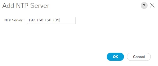
![]() We used the Cisco Nexus switch mgmt0 interface IP here because it is in the same L2 domain as the UCS mgmt0 IPs. You could also use the Nexus NTP IPs, but that traffic would then have to pass through an L3 router.
We used the Cisco Nexus switch mgmt0 interface IP here because it is in the same L2 domain as the UCS mgmt0 IPs. You could also use the Nexus NTP IPs, but that traffic would then have to pass through an L3 router.
8. Click Add NTP Server.
9. Enter <nexus-B-mgmt0-ip> and click OK, then click OK again.
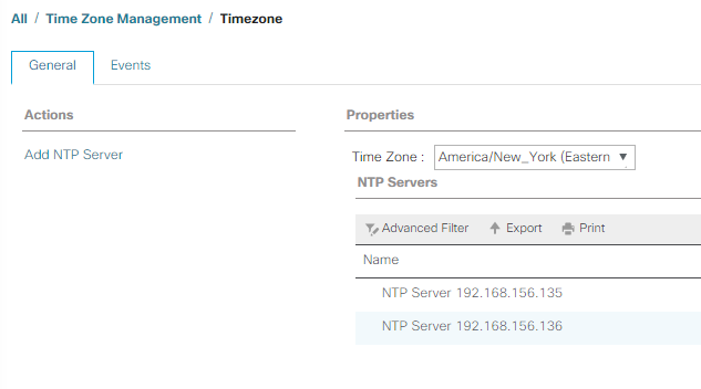
To add one or more additional DNS servers to the UCS environment, follow these steps:
1. In Cisco UCS Manager, click Admin.
2. Expand All > Communications Management.
3. Choose DNS Management.
4. In the Properties pane, choose Specify DNS Server.
5. Enter the IP address of the additional DNS server.
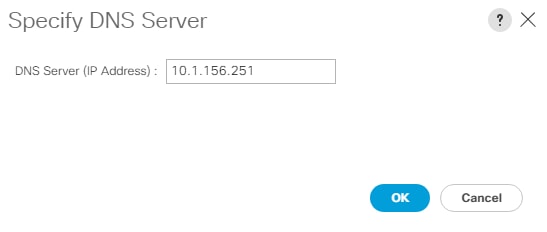
6. Click OK and then click OK again. Repeat this process for any additional DNS servers.
Add an Additional Administrative User
To add an additional locally authenticated Administrative user (flexadmin) to the Cisco UCS environment in case issues arise with the admin user, follow these steps:
1. In Cisco UCS Manager, click Admin.
2. Expand User Management > User Services > Locally Authenticated Users.
3. Right-click Locally Authenticated Users and choose Create User.
4. In the Create User fields it is only necessary to fill in the Login ID, Password, and Confirm Password fields. Fill in the Create User fields according to your local security policy.
5. Leave the Account Status field set to Active.
6. Set Account Expires according to your local security policy.
7. Under Roles, choose admin.
8. Leave Password Required selected for the SSH Type field.
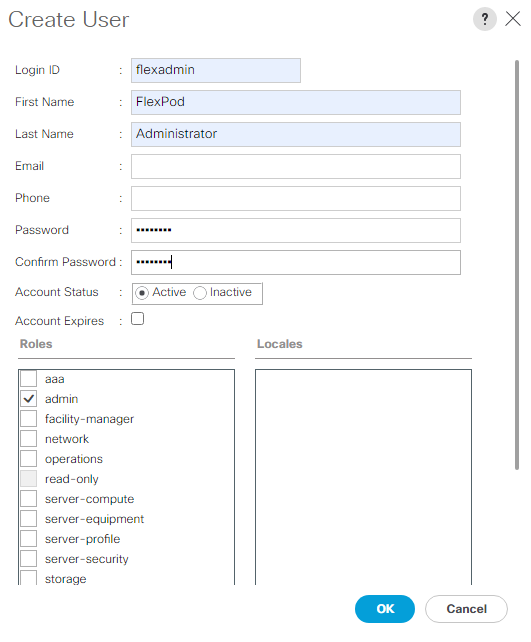
9. Click OK and then click OK again to complete adding the user.
Setting the discovery policy simplifies the addition of Cisco UCS B-Series chassis and of additional fabric extenders for further Cisco UCS C-Series connectivity. To modify the chassis discovery policy, follow these steps:
1. In Cisco UCS Manager, click Equipment and choose the Policies tab.
2. Under Global Policies, set the Chassis/FEX Discovery Policy to match the minimum number of ports that are cabled between the chassis or fabric extenders (FEXes) and the fabric interconnects.
![]() If varying numbers of links between chassis and the Fabric Interconnects will be used, set Action to 2 Link, the minimum recommended number of links for a FlexPod.
If varying numbers of links between chassis and the Fabric Interconnects will be used, set Action to 2 Link, the minimum recommended number of links for a FlexPod.
3. On the 6454 Fabric Interconnects, the Link Grouping Preference is automatically set to Port Channel and is greyed out. On a 6300 Series or 6200 Series Fabric Interconnect, set the Link Grouping Preference to Port Channel. If Backplane Speed Preference appears, leave it set at 40G.
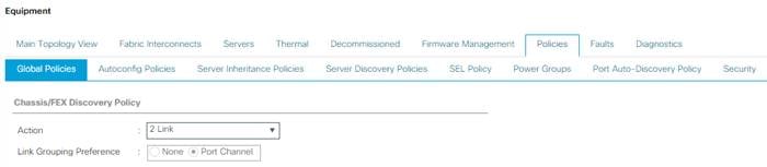
4. If any changes have been made, click Save Changes, and then click OK.
Enable Port Auto-Discovery Policy
Setting the port auto-discovery policy enables automatic discovery of Cisco UCS B-Series chassis server ports. To modify the port auto-discovery policy, follow these steps:
![]() This policy is not applicable to 25G connectivity, manual server ports configuration is required for servers/chassis connected via 25G transceiver. This policy is left in place in case 10G ports are in use.
This policy is not applicable to 25G connectivity, manual server ports configuration is required for servers/chassis connected via 25G transceiver. This policy is left in place in case 10G ports are in use.
1. In Cisco UCS Manager, click Equipment, choose All > Equipment in the Navigation Pane, and choose the Policies tab.
2. Under Port Auto-Discovery Policy, set Auto Configure Server Port to Enabled.
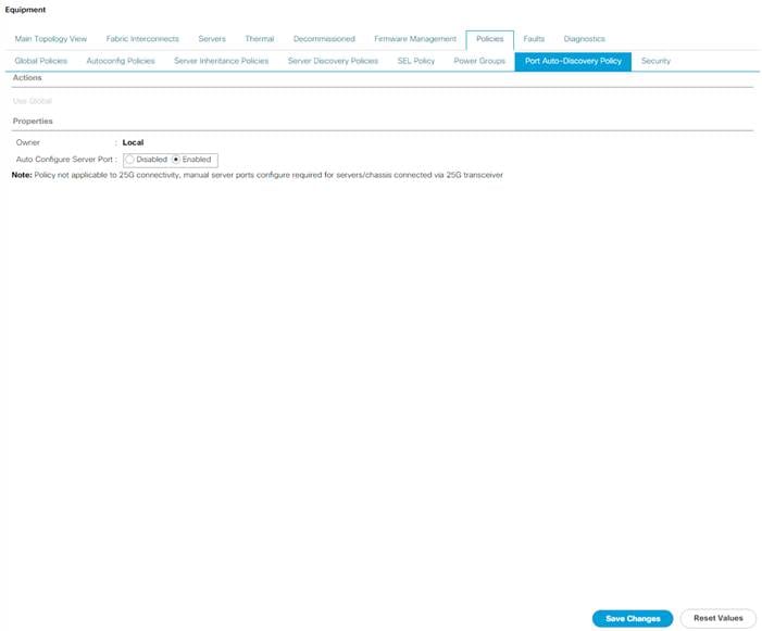
3. Click Save Changes and then OK.
Enable Server and Uplink Ports
To enable and verify server and uplink ports, follow these steps:
1. In Cisco UCS Manager, click Equipment.
2. Expand Equipment > Fabric Interconnects > Fabric Interconnect A (primary) > Fixed Module.
3. Expand and choose Ethernet Ports.
4. Verify that all ports connected to UCS chassis and rack mounts are configured as Server ports and have a status of Up.
5. If any rack mount ports are missing, choose the ports that are connected to Cisco FEXes and direct connect Cisco UCS C-Series servers, right-click them, and choose Configure as Server Port.
6. Click Yes to confirm server ports and click OK.
7. Verify that the ports connected to the chassis, C-series servers and Cisco FEX are now configured as server ports.
8. Choose the ports that are connected to the Cisco Nexus switches, right-click them, and choose Configure as Uplink Port.
9. Click Yes to confirm uplink ports and click OK.
10. Choose Equipment > Fabric Interconnects > Fabric Interconnect B (subordinate) > Fixed Module.
11. Expand and choose Ethernet Ports.
12. Verify that all ports connected to UCS chassis and rack mounts are configured as Server ports and have a status of Up.
13. If any rack mount ports are missing, choose the ports that are connected to Cisco FEXes and direct connect C-series servers, right-click them, and choose Configure as Server Port.
14. Click Yes to confirm server ports and click OK.
15. Verify that the ports connected to the chassis, C-series servers and Cisco FEX are now configured as server ports.
16. Choose the ports that are connected to the Cisco Nexus switches, right-click them, and choose Configure as Uplink Port.
17. Click Yes to confirm the uplink ports and click OK.
Enable Info Policy for Neighbor Discovery
Enabling the info policy allows the Fabric Interconnect neighbor information to display. To modify the info policy, follow these steps:
1. In Cisco UCS Manager, click Equipment, choose All > Equipment in the Navigation Pane, and choose the Policies tab on the right.
2. Under Global Policies, scroll down to Info Policy and choose Enabled for Action.

3. Click Save Changes and then click OK.
4. Under Equipment, choose Fabric Interconnect A or B. On the right, choose the Neighbors tab. CDP information is shown under the LAN tab and LLDP information is shown under the LLDP tab.
Acknowledge Cisco UCS Chassis and FEX
To acknowledge all Cisco UCS chassis and any external FEX modules, follow these steps:
1. In Cisco UCS Manager, click Equipment.
2. Expand Chassis and choose each chassis that is listed.
3. Right-click each chassis and choose Acknowledge Chassis.
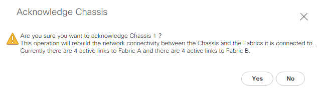
4. Click Yes and then click OK to complete acknowledging the chassis.
5. If Nexus FEXes are part of the configuration, expand Rack Mounts and FEX.
6. Right-click each FEX that is listed and choose Acknowledge FEX.
7. Click Yes and then click OK to complete acknowledging the FEX.
To this point in the Cisco UCS deployment, all items have been deployed at the root level in Cisco UCS Manager. To allow Cisco UCS to be shared among different projects, you need to create Cisco UCS Organizations. In this validation, the organization for this FlexPod deployment is FlexPod. To create an organization, follow these steps:
1. In Cisco UCS Manager, click Servers.
2. In the Navigation Pane, expand Servers > Service Profiles.
3. Right-click root under Service Profiles and choose Create Organization.
4. Provide a name for the Organization to indicate this FlexPod deployment and optionally provide a Description.
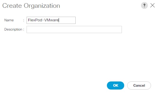
5. Click OK then click OK again to complete creating the organization.
Create a WWNN Pool for FC Boot (FCP)
In this FlexPod implementation, a WWNN pool is created at the root organization level to avoid WWNN address pool overlaps. If your deployment plan calls for different WWNN ranges in different UCS organizations, place the WWNN pool at the organizational level. To configure the necessary WWNN pool for the Cisco UCS environment, follow these steps using Cisco UCS Manager.
1. Choose SAN.
2. Choose Pools > root.
3. Right-click WWNN Pools under the root organization.
4. Choose Create WWNN Pool to create the WWNN pool.
5. Enter WWNN-Pool for the name of the WWNN pool.
6. Optional: Enter a description for the WWNN pool.
7. Choose Sequential for Assignment Order.
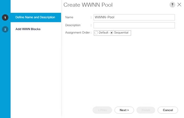
8. Click Next.
9. Click Add.
10. Modify the From field as necessary for the Cisco UCS Environment.
![]() Modifications of the WWNN block, as well as the WWPN and MAC Addresses, can convey identifying information for the Cisco UCS domain. Within the From field in our example, the sixth and seventh octets were changed from 00:00 to A1:60 to represent these WWNNs being in the A16 cabinet.
Modifications of the WWNN block, as well as the WWPN and MAC Addresses, can convey identifying information for the Cisco UCS domain. Within the From field in our example, the sixth and seventh octets were changed from 00:00 to A1:60 to represent these WWNNs being in the A16 cabinet.
![]() When there are multiple UCS domains sitting in adjacency, it is important that these blocks; the WWNN, WWPN, and MAC, hold differing values between each set.
When there are multiple UCS domains sitting in adjacency, it is important that these blocks; the WWNN, WWPN, and MAC, hold differing values between each set.
11. Specify a size of the WWNN block sufficient to support the available server resources. In this example, with the WWNN block modification, a maximum of 256 addresses are available.
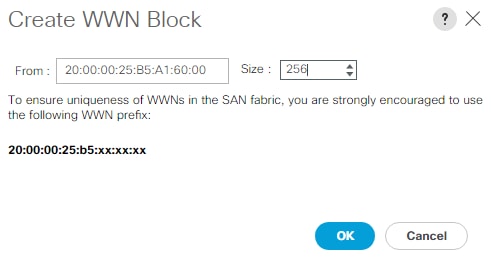
12. Click OK.
13. Click Finish and click OK to complete creating the WWNN pool.
Create WWPN Pools (FCP)
In this FlexPod implementation, WWPN address pools are created at the root organization level to avoid WWPN address pool overlaps. If your deployment plan calls for different WWPN address ranges in different UCS organizations, place the WWPN pools at the organizational level. To configure the necessary WWPN pools for the Cisco UCS environment, follow these steps:
1. In Cisco UCS Manager, click SAN.
2. Choose Pools > root.
![]() In this procedure, two WWPN pools are created, one for each switching fabric.
In this procedure, two WWPN pools are created, one for each switching fabric.
3. Right-click WWPN Pools under the root organization.
4. Choose Create WWPN Pool to create the WWPN pool.
5. Enter WWPN-Pool-A as the name of the WWPN pool.
6. Optional: Enter a description for the WWPN pool.
7. Choose Sequential for Assignment Order.
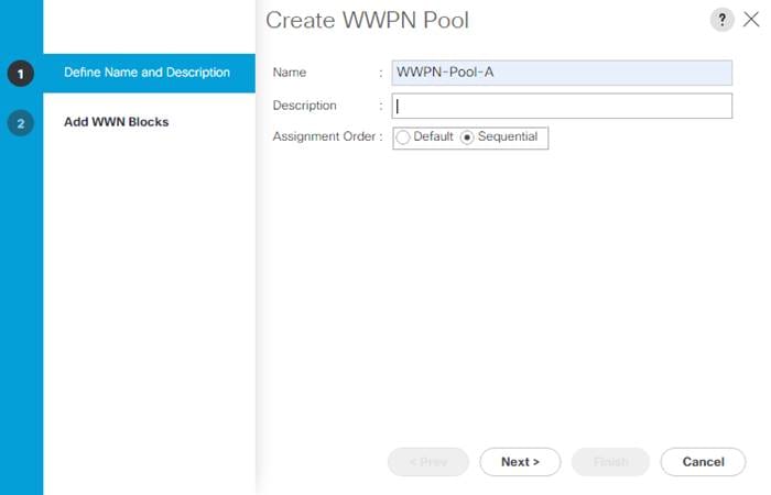
8. Click Next.
9. Click Add.
10. Specify a starting WWPN.
![]() For the FlexPod solution, the recommendation is to place A in the next-to-last octet of the starting WWPN to identify all of the WWPNs as fabric A addresses. Merging this with the pattern we used for the WWNN we see a WWPN block starting with 20:00:00:25:B5:A1:6A:00
For the FlexPod solution, the recommendation is to place A in the next-to-last octet of the starting WWPN to identify all of the WWPNs as fabric A addresses. Merging this with the pattern we used for the WWNN we see a WWPN block starting with 20:00:00:25:B5:A1:6A:00
![]() Specify a size for the WWPN pool that is sufficient to support the available blade or server resources remembering that servers could have multiple vHBAs and unassociated service profiles could be created. In this example, with the WWPN block modification, a maximum of 256 addresses are available.
Specify a size for the WWPN pool that is sufficient to support the available blade or server resources remembering that servers could have multiple vHBAs and unassociated service profiles could be created. In this example, with the WWPN block modification, a maximum of 256 addresses are available.

11. Click OK.
12. Click Finish.
13. In the confirmation message, click OK.
14. Right-click WWPN Pools under the root organization.
15. Choose Create WWPN Pool to create the WWPN pool.
16. Enter WWPN-Pool-B as the name of the WWPN pool.
17. Optional: Enter a description for the WWPN pool.
18. Choose Sequential for Assignment Order.
19. Click Next.
20. Click Add.
21. Specify a starting WWPN.
![]() For the FlexPod solution, the recommendation is to place B in the next-to-last octet of the starting WWPN to identify all of the WWPNs as fabric B addresses. Merging this with the pattern we used for the WWNN we see a WWPN block starting with 20:00:00:25:B5:A1:6B:00.
For the FlexPod solution, the recommendation is to place B in the next-to-last octet of the starting WWPN to identify all of the WWPNs as fabric B addresses. Merging this with the pattern we used for the WWNN we see a WWPN block starting with 20:00:00:25:B5:A1:6B:00.
![]() Specify a size for the WWPN address pool that is sufficient to support the available blade or server resources remembering that servers could have multiple vHBAs and unassociated service profiles could be created. In this example, with the WWPN block modification, a maximum of 256 addresses are available.
Specify a size for the WWPN address pool that is sufficient to support the available blade or server resources remembering that servers could have multiple vHBAs and unassociated service profiles could be created. In this example, with the WWPN block modification, a maximum of 256 addresses are available.
22. Click OK.
23. Click Finish.
24. In the confirmation message, click OK.
Create VSANs (FCP)
To configure the necessary virtual storage area networks (VSANs) for the FlexPod Organization in the Cisco UCS environment, follow these steps:
1. In Cisco UCS Manager, click SAN.
![]() In this procedure, two VSANs are created, one for each SAN switching fabric.
In this procedure, two VSANs are created, one for each SAN switching fabric.
2. Choose SAN > SAN Cloud.
3. Right-click VSANs.
4. Choose Create VSAN.
5. Enter FlexPod-Fabric-A as the name of the VSAN to be used for Fabric A.
6. Leave FC Zoning set at Disabled.
7. Choose Fabric A.
8. Enter a unique VSAN ID and a corresponding FCoE VLAN ID that matches the configuration in the MDS switch for Fabric A. It is recommended to use the same ID for both parameters and to use something other than 1.
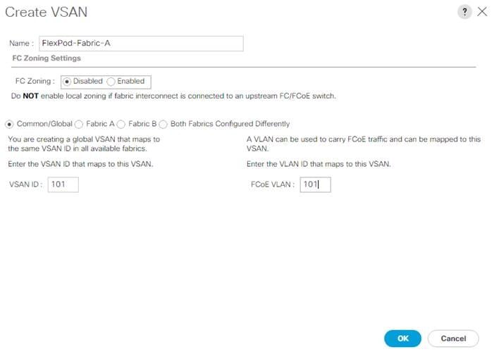
9. Click OK and then click OK again.
10. Under SAN Cloud, right-click VSANs.
11. Choose Create VSAN.
12. Enter FlexPod-Fabric-B as the name of the VSAN to be used for Fabric B.
13. Leave FC Zoning set at Disabled.
14. Choose Fabric B.
15. Enter a unique VSAN ID and a corresponding FCoE VLAN ID that matches the configuration in the MDS switch for Fabric B. It is recommended use the same ID for both parameters and to use something other than 1.
16. Click OK and then click OK again.
Enable FC Uplink VSAN Trunking (FCP)
To enable VSAN trunking on the FC Uplinks in the Cisco UCS environment, follow these steps:
![]() Enabling VSAN trunking is optional. It is important that the Cisco MDS VSAN trunking configuration match the configuration set in Cisco UCS Manager or be set to auto.
Enabling VSAN trunking is optional. It is important that the Cisco MDS VSAN trunking configuration match the configuration set in Cisco UCS Manager or be set to auto.
1. In Cisco UCS Manager, click SAN.
2. Expand SAN > SAN Cloud.
3. Choose Fabric A and in the Actions pane choose Enable FC Uplink Trunking.
4. Click Yes on the Confirmation and Warning.
5. Click OK.
6. Choose Fabric B and in the Actions pane choose Enable FC Uplink Trunking.
7. Click Yes on the Confirmation and Warning.
8. Click OK.
Create FC Uplink Port Channels (FCP)
To create the FC Uplink Port Channels and assign the appropriate VSANs to them for the Cisco UCS environment, follow these steps:
1. In Cisco UCS Manager, click SAN.
2. Choose SAN > SAN Cloud.
3. Expand Fabric A and choose FC Port Channels.
4. Right-click FC Port Channels and choose Create FC Port Channel.
5. Set a unique ID for the port channel and provide a unique name for the port channel.
6. Click Next.
7. Choose the appropriate Port Channel Admin Speed.
8. Choose the ports connected to Cisco MDS 9132T A and use >> to add them to the port channel.
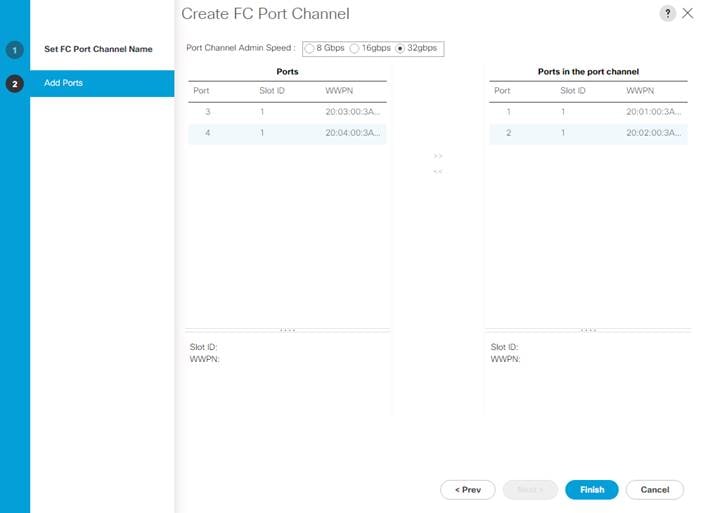
9. Click Finish to complete creating the port channel.
10. Click OK on the confirmation.
11. Under FC Port-Channels, choose the newly created port channel.
12. From the drop-down list to choose the FlexPod-Fabric-A VSAN.
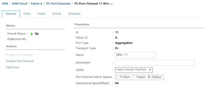
13. Click Save Changes to assign the VSAN.
14. Click OK.
16. Expand Fabric B and choose FC Port Channels.
17. Right-click FC Port Channels and choose Create FC Port Channel.
18. Set a unique ID for the port channel and provide a unique name for the port channel.
19. Click Next.
20. Choose the ports connected to Cisco MDS 9132T B and use >> to add them to the port channel.
21. Click Finish to complete creating the port channel.
22. Click OK on the confirmation.
23. Under FC Port-Channels, choose the newly created port channel.
24. In the right pane, use the drop-down to choose the FlexPod-Fabric-B VSAN.
25. Click Save Changes to assign the VSAN.
26. Click OK.
27. On the left under FC Port Channels, expand the newly created FC Port-Channel. Under the FC Port-Channel choose the first FC Interface. Enter a User Label to indicate the connectivity on the MDS 9132T switch, such as <mds-B-hostname>:fc1/5. Click Save Changes and OK. Repeat this process for the other FC Interface.
Disable Unused FC Uplink Ports (FCP)
When Unified Ports were configured earlier in this procedure, on the Cisco UCS 6454 FI and the Cisco UCS 6332-16UP FI, FC ports were configured in groups. Because of this group configuration, some FC ports are unused and need to be disabled to prevent alerts. To disable the unused FC ports 1 and 2 on the Cisco UCS 6454 FIs, follow these steps:
1. In Cisco UCS Manager, click SAN.
2. In the Navigation Pane, expand SAN > SAN Cloud > Fabric A > Uplink FC Interfaces.
3. Right-click FC Interface 1/3 and choose Disable Interface.
4. Click Yes and OK to complete disabling FC Interface 1/3.
5. Repeat steps 1 - 4 to disable FC Interface 1/4.
6. In the Navigation Pane, expand SAN > SAN Cloud > Fabric B > Uplink FC Interfaces.
7. Right-click FC Interface 1/3 and choose Disable Interface.
8. Click Yes and OK to complete disabling FC Interface 1/3.
9. Repeat steps 1 - 8 to disable FC Interface 1/4.
Create vHBA Templates (FCP)
To create the necessary virtual host bus adapter (vHBA) templates for the Cisco UCS environment within the FlexPod organization, follow these steps:
1. In Cisco UCS Manager, click SAN.
2. Expand Policies > root > Sub-Organizations > FlexPod.
3. Right-click vHBA Templates under the FlexPod Organization.
4. Choose Create vHBA Template.
5. Enter vHBA-A as the vHBA template name.
6. Keep Fabric A selected.
7. Leave Redundancy Type set to No Redundancy.
8. Choose the FlexPod-Fabric-A VSAN.
9. Leave Initial Template as the Template Type.
10. Choose WWPN-Pool-A as the WWPN Pool.
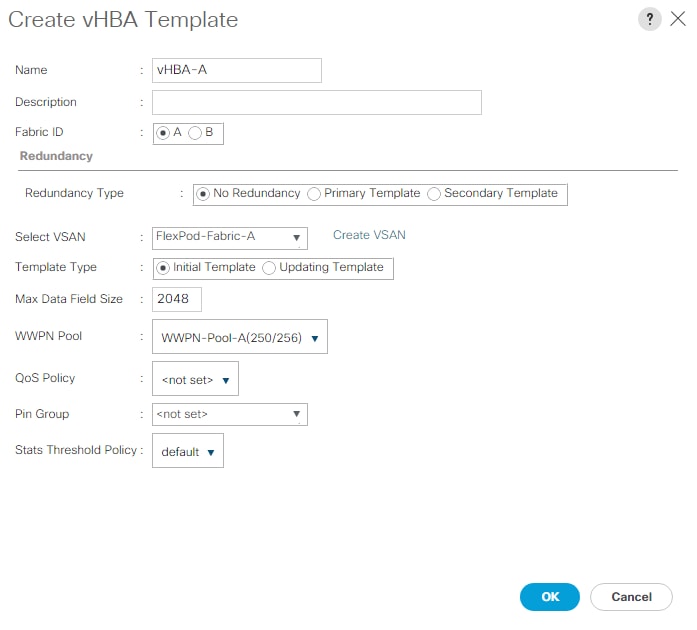
11. Click OK to create the vHBA template.
12. Click OK.
13. Right-click vHBA Templates under the FlexPod Organization.
14. Choose Create vHBA Template.
15. Enter vHBA-B as the vHBA template name.
16. Choose B as the Fabric ID.
17. Leave Redundancy Type set to No Redundancy.
18. Choose the FlexPod-Fabric-B VSAN.
19. Leave Initial Template as the Template Type.
20. Choose WWPN-Pool-B as the WWPN Pool.
21. Click OK to create the vHBA template.
22. Click OK.
Create SAN Connectivity Policy (FCP)
To configure the necessary Infrastructure SAN Connectivity Policy within the FlexPod organization, follow these steps:
1. In Cisco UCS Manager, click SAN.
2. Choose SAN > Policies > root > Sub-Organizations > FlexPod.
3. Right-click SAN Connectivity Policies under the FlexPod Organization.
4. Choose Create SAN Connectivity Policy.
5. Enter FC-Boot as the name of the policy.
6. Choose the previously created WWNN-Pool for the WWNN Assignment.
7. Click Add at the bottom to add a vHBA.
8. In the Create vHBA dialog box, enter FCP-Fabric-A as the name of the vHBA.
9. Check the box for Use vHBA Template.
10. In the vHBA Template list, choose vHBA-A.
11. In the Adapter Policy list, choose VMWare.
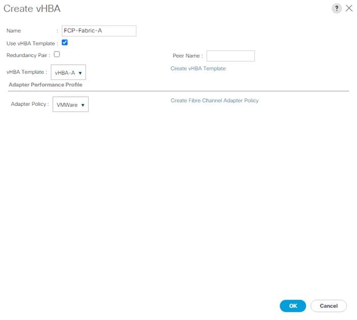
12. Click OK.
13. Click Add to add a second vHBA.
14. In the Create vHBA dialog box, enter FCP-Fabric-B as the name of the vHBA.
15. Check the box for Use vHBA Template.
16. In the vHBA Template list, choose vHBA-B.
17. In the Adapter Policy list, choose VMWare.
18. Click OK.
19. If configuring FC-NVMe in this FlexPod, click Add at the bottom to add an FC-NVMe vHBA.
20. In the Create vHBA dialog box, enter FC-NVMe-Fabric-A as the name of the vHBA.
21. Check the box for Use vHBA Template.
22. In the vHBA Template list, choose vHBA-A.
23. In the Adapter Policy list, choose FCNVMeInitiator.

24. Click OK.
25. Click Add at the bottom to add a second FC-NVMe vHBA.
26. In the Create vHBA dialog box, enter FC-NVMe-Fabric-B as the name of the vHBA.
27. Check the box for Use vHBA Template.
28. In the vHBA Template list, choose vHBA-B.
29. In the Adapter Policy list, choose FCNVMeInitiator.
30. Click OK.
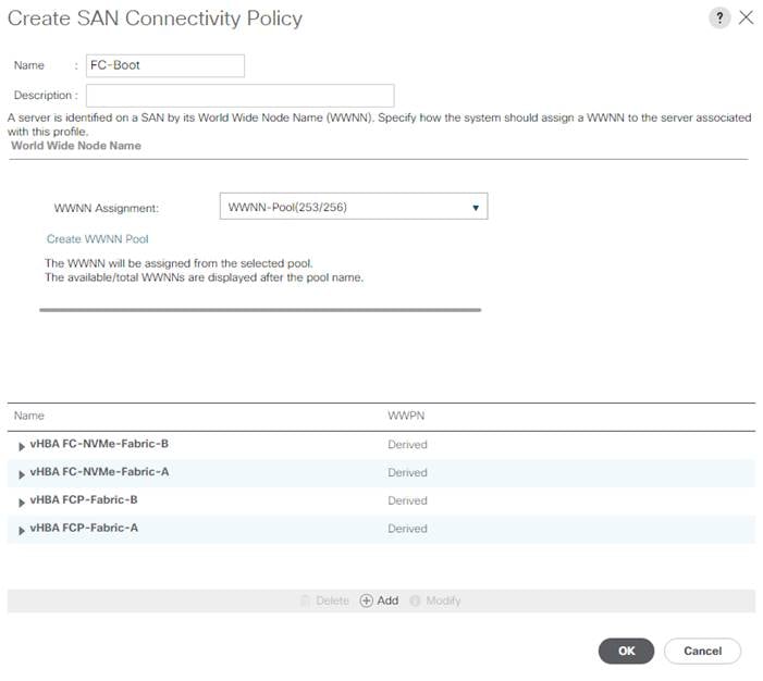
31. Click OK to create the SAN Connectivity Policy.
32. Click OK to confirm creation.
Add Block of IP Addresses for KVM Access
To create a block of IP addresses for in band server Keyboard, Video, Mouse (KVM) access in the Cisco UCS environment, follow these steps:
1. In Cisco UCS Manager, click LAN.
2. Expand Pools > root > IP Pools.
3. Right-click IP Pool ext-mgmt and choose Create Block of IPv4 Addresses.
4. Enter the starting IP address of the block, number of IP addresses required, and the subnet mask and gateway information. Optionally, enter the Primary and Secondary DNS server addresses.
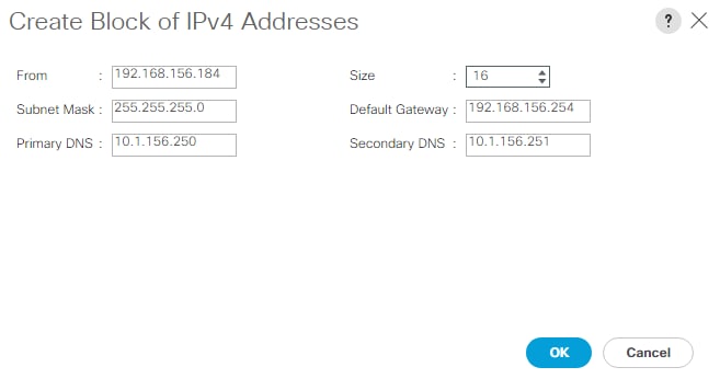
5. Click OK to create the block.
6. Click OK in the confirmation message.
Create Uplink Port Channels to Cisco Nexus Switches
To configure the necessary port channels out of the Cisco UCS environment, follow these steps:
1. In Cisco UCS Manager, click LAN.
![]() In this procedure, two port channels are created: one from fabric A to both Cisco Nexus switches and one from fabric B to both Cisco Nexus switches.
In this procedure, two port channels are created: one from fabric A to both Cisco Nexus switches and one from fabric B to both Cisco Nexus switches.
2. Under LAN > LAN Cloud, expand the Fabric A tree.
3. Right-click Port Channels under Fabric A.
4. Choose Create Port Channel.
5. Enter 145 as the unique ID of the port channel.
6. Enter Po145-Nexus as the name of the port channel.
7. Click Next.
8. Choose the uplink ports connected to the Nexus switches to be added to the port channel.
9. Click >> to add the ports to the port channel.
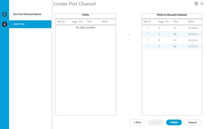
10. Click Finish to create the port channel.
11. Click OK.
12. In the navigation pane, under LAN > LAN Cloud > Fabric A > Port Channels, choose Port-Channel 145. Ensure Auto is selected for the Admin Speed. After a few minutes, verify that the Overall Status is Up, and the Operational Speed is correct.
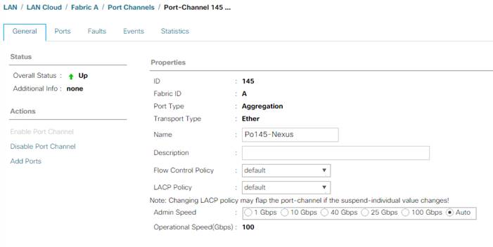
13. In the navigation pane, under LAN > LAN Cloud, expand the Fabric B tree.
14. Right-click Port Channels under Fabric B.
15. Choose Create Port Channel.
16. Enter 146 as the unique ID of the port channel.
17. Enter Po146-Nexus as the name of the port channel.
18. Click Next.
19. Choose the ports connected to the Nexus switches to be added to the port channel:
20. Click >> to add the ports to the port channel.
21. Click Finish to create the port channel.
22. Click OK.
23. In the navigation pane, under LAN > LAN Cloud > Fabric B > Port Channels, choose Port-Channel 146. Ensure Auto is selected for the Admin Speed. After a few minutes, verify that the Overall Status is Up, and the Operational Speed is correct.
24. In the navigation pane, under LAN > LAN Cloud > Fabric A > Port Channels, expand Port-Channel 145. Under Port-Channel 145, choose Eth Interface 1/45. In the center pane under Properties, enter a User Label to indicate the port connectivity, such as <nexus-a-hostname>:Eth1/21. Click Save Changes and OK. Repeat this process for the remaining seven uplink ports.
Add UDLD to Uplink Port Channels
To configure the unidirectional link detection (UDLD) on the Uplink Port Channels to the Cisco Nexus switches for fibre optic connections, follow these steps:
1. In Cisco UCS Manager, click LAN.
2. Expand Policies > LAN Cloud > UDLD Link Policy.
3. Right-click UDLD Link Policy and choose Create UDLD Link Policy.
4. Name the Policy UDLD-Normal and choose Enabled for the Admin State and Normal for the Mode.
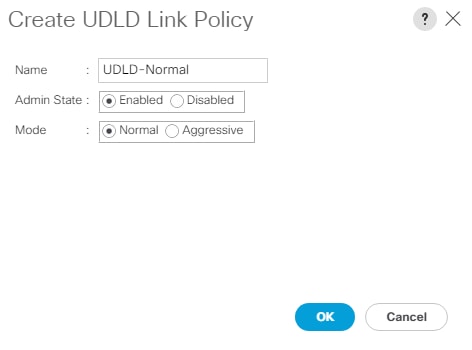
5. Click OK, then click OK again to complete creating the policy.
6. Expand Policies > LAN Cloud > Link Profile.
7. Right-click Link Profile and choose Create Link Profile.
8. Name the Profile UDLD-Normal and choose the UDLD-Normal Link Policy created above.
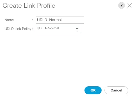
9. Click OK, then click OK again to complete creating the profile.
10. In the navigation pane, under LAN > LAN Cloud > Fabric A > Port Channels, expand Port-Channel 145. Choose the first Eth Interface under Port-Channel 145. From the drop-down list, choose the UDLD-Normal Link Profile created above, click Save Changes and OK. Repeat this process for each Eth Interface under Port-Channel 145 and for each Eth Interface under Port-Channel 146 on Fabric B.
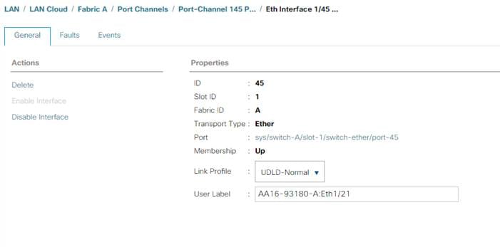
Set Jumbo Frames in Cisco UCS Fabric
Jumbo Frames are used in FlexPod for the NFS and iSCSI storage protocols. The normal best practice in FlexPod has been to set the MTU of the Best Effort QoS System Class in Cisco UCS Manager to 9216 for Jumbo Frames. In the Cisco UCS 6454 Fabric Interconnect with Cisco UCS Manager version 4.0 software the MTU for the Best Effort QoS System Class is fixed at normal and cannot be changed. With this setting of normal in the 6454, Jumbo Frames can pass through the Cisco UCS fabric without being dropped. In Cisco UCS Manager version 4.1 and above, the MTU for the Best Effort QoS System Class is again settable. To configure jumbo frames in the Cisco UCS fabric, follow these steps:
1. In Cisco UCS Manager, click LAN.
2. Expand LAN > LAN Cloud > QoS System Class.
3. In the right pane, click the General tab.
4. On the Best Effort row, enter 9216 in the box under the MTU column.
5. Click Save Changes.
6. Click OK.
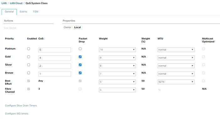
![]() Only the Fibre Channel and Best Effort QoS System Classes are enabled in this FlexPod implementation. The Cisco UCS and Cisco Nexus switches are intentionally configured this way so that all IP traffic within the FlexPod will be treated as Best Effort. Enabling the other QoS System Classes without having a comprehensive, end-to-end QoS setup in place can cause difficult to troubleshoot issues. For example, NetApp storage controllers by default mark IP-based, VLAN-tagged packets with a CoS value of 4. With the default configuration on the Nexus switches in this implementation, storage packets will pass through the switches and into the Cisco UCS Fabric Interconnects with CoS 4 set in the packet header. If the Gold QoS System Class in the Cisco UCS is enabled and the corresponding CoS value left at 4, these storage packets will be treated according to that class and if Jumbo Frames is being used for the storage protocols, but the MTU of the Gold QoS System Class is not set to Jumbo (9216), packet drops will occur. Also, if the Platinum class is enabled, the MTU must be set to 9216 to use Jumbo Frames in that class.
Only the Fibre Channel and Best Effort QoS System Classes are enabled in this FlexPod implementation. The Cisco UCS and Cisco Nexus switches are intentionally configured this way so that all IP traffic within the FlexPod will be treated as Best Effort. Enabling the other QoS System Classes without having a comprehensive, end-to-end QoS setup in place can cause difficult to troubleshoot issues. For example, NetApp storage controllers by default mark IP-based, VLAN-tagged packets with a CoS value of 4. With the default configuration on the Nexus switches in this implementation, storage packets will pass through the switches and into the Cisco UCS Fabric Interconnects with CoS 4 set in the packet header. If the Gold QoS System Class in the Cisco UCS is enabled and the corresponding CoS value left at 4, these storage packets will be treated according to that class and if Jumbo Frames is being used for the storage protocols, but the MTU of the Gold QoS System Class is not set to Jumbo (9216), packet drops will occur. Also, if the Platinum class is enabled, the MTU must be set to 9216 to use Jumbo Frames in that class.
To configure the necessary virtual local area networks (VLANs) for the Cisco UCS environment, follow these steps:
1. In Cisco UCS Manager, click LAN.
![]() In this procedure, six unique VLANs are created. See Table2.
In this procedure, six unique VLANs are created. See Table2.
2. Expand LAN > LAN Cloud.
3. Right-click VLANs.
4. Choose Create VLANs.
5. Enter Native-VLAN as the name of the VLAN to be used as the native VLAN.
6. Keep the Common/Global option selected for the scope of the VLAN.
7. Enter the native VLAN ID.
8. Keep the Sharing Type as None.
9. Click OK and then click OK again.
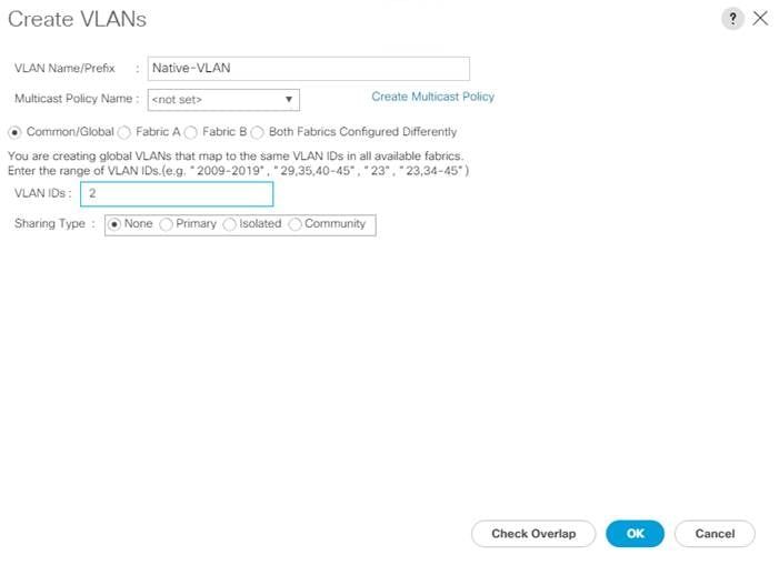
10. Expand the list of VLANs in the navigation pane, right-click the newly created Native-VLAN and choose Set as Native VLAN.
11. Click Yes and then click OK.
12. Right-click VLANs.
13. Choose Create VLANs
14. Enter IB-MGMT as the name of the VLAN to be used for management traffic.
![]() Modify these VLAN names as necessary for your environment.
Modify these VLAN names as necessary for your environment.
15. Keep the Common/Global option selected for the scope of the VLAN.
16. Enter the In-Band management VLAN ID.
17. Keep the Sharing Type as None.
18. Click OK, and then click OK again.
19. Right-click VLANs.
20. Choose Create VLANs.
21. Enter OOB-MGMT as the name of the VLAN to be used for Out-of-Band Management.
22. Keep the Common/Global option selected for the scope of the VLAN.
23. Enter the Infrastructure OOB-MGMT VLAN ID.
24. Keep the Sharing Type as None.
25. Click OK, and then click OK again.
26. Right-click VLANs.
27. Choose Create VLANs.
28. Enter Infra-NFS as the name of the VLAN to be used for NFS.
29. Keep the Common/Global option selected for the scope of the VLAN.
30. Enter the Infrastructure NFS VLAN ID.
31. Keep the Sharing Type as None.
32. Click OK, and then click OK again.
33. Right-click VLANs.
34. Choose Create VLANs.
35. Enter vMotion as the name of the VLAN to be used for vMotion.
36. Keep the Common/Global option selected for the scope of the VLAN.
37. Enter the vMotion VLAN ID.
38. Keep the Sharing Type as None.
39. Click OK and then click OK again.
40. Choose Create VLANs.
41. Enter VM-Traffic as the name of the VLAN to be used for VM Traffic.
42. Keep the Common/Global option selected for the scope of the VLAN.
43. Enter the VM-Traffic VLAN ID.
44. Keep the Sharing Type as None.
45. Click OK and then click OK again.
![]() While the Infra-iSCSI VLANs are included in the Appendix, they are also shown below.
While the Infra-iSCSI VLANs are included in the Appendix, they are also shown below.
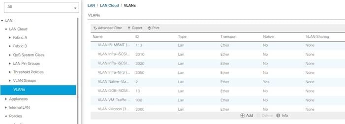
In this FlexPod implementation, MAC address pools are created at the root organization level to avoid MAC address pool overlaps. If your deployment plan calls for different MAC address ranges in different UCS organizations, place the MAC pools at the organizational level. To configure the necessary MAC address pools for the Cisco UCS environment, follow these steps:
1. In Cisco UCS Manager, click LAN.
2. Expand Pools > root.
![]() In this procedure, two MAC address pools are created, one for each switching fabric.
In this procedure, two MAC address pools are created, one for each switching fabric.
3. Right-click MAC Pools under the root organization.
4. Choose Create MAC Pool to create the MAC address pool.
5. Enter MAC-Pool-A as the name of the MAC pool.
6. Optional: Enter a description for the MAC pool.
7. Choose Sequential as the option for Assignment Order.
8. Click Next.
9. Click Add.
10. Specify a starting MAC address.
![]() For the FlexPod solution, the recommendation is to place A in the next-to-last octet of the starting MAC address to identify all of the MAC addresses as fabric A addresses. In our example, we have carried forward the example of also embedding the cabinet number information giving us 00:25:B5:A1:6A:00 as our first MAC address.
For the FlexPod solution, the recommendation is to place A in the next-to-last octet of the starting MAC address to identify all of the MAC addresses as fabric A addresses. In our example, we have carried forward the example of also embedding the cabinet number information giving us 00:25:B5:A1:6A:00 as our first MAC address.
11. Specify a size for the MAC address pool that is sufficient to support the available blade or server resources remembering that a server may contain multiple vNICs and that multiple unassociated Service Profiles can be created. In this example, with the MAC block modification, a maximum of 256 addresses are available.
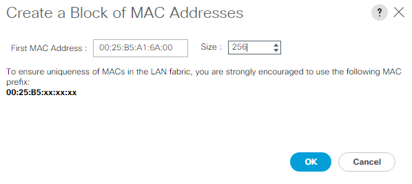
12. Click OK.
13. Click Finish.
14. In the confirmation message, click OK.
15. Right-click MAC Pools under the root organization.
16. Choose Create MAC Pool to create the MAC address pool.
17. Enter MAC-Pool-B as the name of the MAC pool.
18. Optional: Enter a description for the MAC pool.
19. Choose Sequential as the option for Assignment Order.
20. Click Next.
21. Click Add.
22. Specify a starting MAC address.
![]() For the FlexPod solution, it is recommended to place B in the next to last octet of the starting MAC address to identify all the MAC addresses in this pool as fabric B addresses. Once again, we carried forward our example of also embedding the cabinet number information giving us 00:25:B5:A1:6B:00 as our first MAC address.
For the FlexPod solution, it is recommended to place B in the next to last octet of the starting MAC address to identify all the MAC addresses in this pool as fabric B addresses. Once again, we carried forward our example of also embedding the cabinet number information giving us 00:25:B5:A1:6B:00 as our first MAC address.
23. Specify a size for the MAC address pool that is sufficient to support the available blade or server resources remembering that a server may contain multiple vNICs and that multiple unassociated Service Profiles can be created. In this example, with the MAC block modification, a maximum of 256 addresses are available.
24. Click OK.
25. Click Finish.
26. In the confirmation message, click OK.
Create Network Control Policy for Cisco Discovery Protocol (CDP) and Link Layer Discovery Protocol (LLDP)
To create a network control policy that enables CDP and LLDP on server virtual network controller (vNIC) ports, follow these steps:
1. In Cisco UCS Manager, click LAN.
2. Expand Policies > root.
3. Right-click Network Control Policies.
4. Choose Create Network Control Policy.
5. Enter Enable-CDP-LLDP as the policy name.
6. For CDP, choose the Enabled option.
7. For LLDP, scroll down and choose Enabled for both Transmit and Receive.
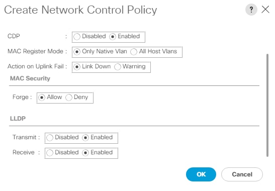
8. Click OK to create the network control policy.
9. Click OK.
To create multiple virtual network interface card (vNIC) templates within the FlexPod organization, follow these steps. A total of 4 vNIC Templates will be created. Two of the vNIC templates (vSwitch0-A and vSwitch0-B) will be created for vNICs to connect to VMware ESXi vSwitch0. vSwitch0 will have port groups for the IB-MGMT, OOB-MGMT, Infra-NFS, vMotion, and VM-Traffic VLANs. The third and fourth vNIC templates (vDS0-A and vDS0-B) will be created for vNICs to connect to the VMware Virtual Distributed Switch (vDS0). The vDS will have port groups for the vMotion and VM-Traffic VLANs. The vMotion VLAN is being placed on the vDS to allow QoS marking of vMotion packets to occur within the vDS if QoS policies need to be applied to vMotion in the future, and it is also left on vSwitch0. Any tenant or application VLANs can be placed on the vDS in the future.
Create Infrastructure vNIC Templates
To create the infrastructure vNIC templates, follow these steps:
1. In Cisco UCS Manager, click LAN.
2. Expand Policies > root > Sub-Organizations > FlexPod.
3. Under the FlexPod Organization, right-click vNIC Templates.
4. Choose Create vNIC Template.
5. Enter vSwitch0-A as the vNIC template name.
6. Keep Fabric A selected.
7. Do not select the Enable Failover checkbox.
8. Choose Primary Template for Redundancy Type.
9. Leave the Peer Redundancy Template set to <not set>.
10. Under Target, make sure that only the Adapter checkbox is selected.
11. Choose Updating Template as the Template Type.
12. Under VLANs, check the boxes for IB-MGMT, OOB-MGMT, Infra-NFS and vMotion VLANs.
13. Set IB-MGMT as the native VLAN.
![]() You’re setting IB-MGMT as the native VLAN here so that DHCP will work on the ESXi host without any modification. Remember to set the VLAN to 0 or not set the VLAN for any IB-MGMT port groups in VMware ESXi vSwitch0.
You’re setting IB-MGMT as the native VLAN here so that DHCP will work on the ESXi host without any modification. Remember to set the VLAN to 0 or not set the VLAN for any IB-MGMT port groups in VMware ESXi vSwitch0.
14. Choose vNIC Name for the CDN Source.
15. For MTU, enter 9000.
16. In the MAC Pool list, choose MAC-Pool-A.
17. In the Network Control Policy list, choose Enable-CDP-LLDP.
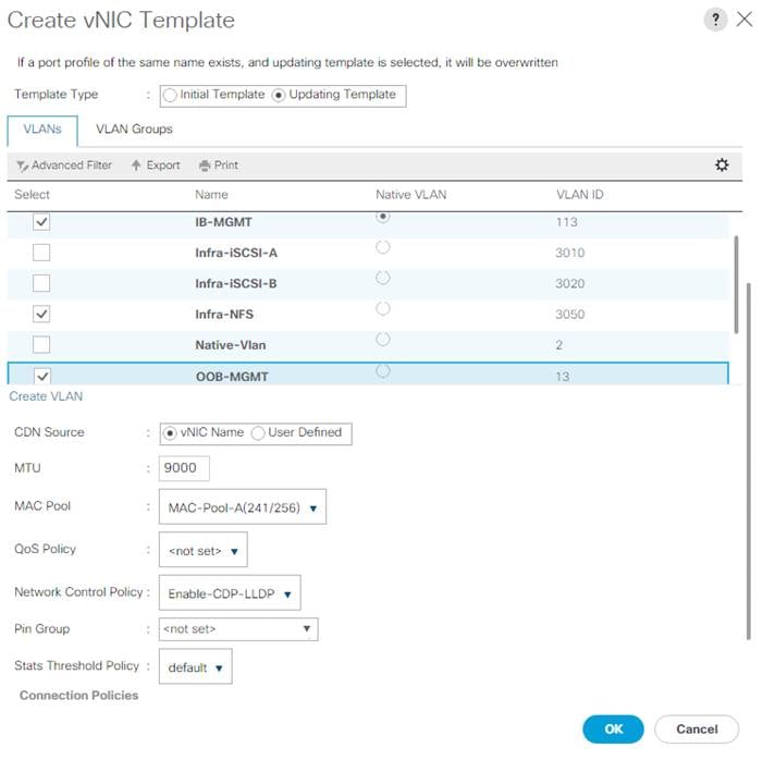
18. Click OK to create the vNIC template.
19. Click OK.
20. Under the FlexPod organization, right-click vNIC Templates.
21. Choose Create vNIC Template.
22. Enter vSwitch0-B as the vNIC template name.
23. Choose Fabric B.
24. Do not select the Enable Failover checkbox.
25. Set Redundancy Type to Secondary Template.
26. Choose vSwitch0-A for the Peer Redundancy Template.
27. In the MAC Pool list, choose MAC-Pool-B.
![]() The MAC Pool is all that needs to be selected for the Secondary Template, all other values will either be propagated from the Primary Template or set at default values.
The MAC Pool is all that needs to be selected for the Secondary Template, all other values will either be propagated from the Primary Template or set at default values.
28. Click OK to create the vNIC template.
29. Click OK.
30. Under the FlexPod Organization, right-click vNIC Templates.
31. Choose Create vNIC Template.
32. Enter vDS0-A as the vNIC template name.
33. Keep Fabric A selected.
34. Do not select the Enable Failover checkbox.
35. Choose Primary Template for Redundancy Type.
36. Leave the Peer Redundancy Template set to <not set>.
37. Under Target, make sure that only the Adapter checkbox is selected.
38. Choose Updating Template as the Template Type.
39. Under VLANs, choose the checkboxes for vMotion, VM-Traffic, and Native-VLAN VLANs.
40. Set Native-VLAN as the native VLAN.
41. Choose vNIC Name for the CDN Source.
42. For MTU, enter 9000.
43. In the MAC Pool list, choose MAC-Pool-A.
44. In the Network Control Policy list, choose Enable-CDP-LLDP.
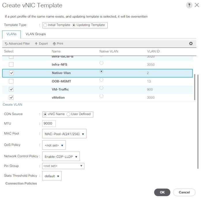
45. Click OK to create the vNIC template.
46. Click OK.
47. Under the FlexPod organization, right-click vNIC Templates.
48. Choose Create vNIC Template.
49. Enter vDS0-B as the vNIC template name.
50. Choose Fabric B.
51. Do not select the Enable Failover checkbox.
52. Set Redundancy Type to Secondary Template.
53. Choose vDS0-A for the Peer Redundancy Template.
54. In the MAC Pool list, choose MAC-Pool-B.
![]() The MAC Pool is all that needs to be selected for the Secondary Template, all other values will either be propagated from the Primary Template or set at default values.
The MAC Pool is all that needs to be selected for the Secondary Template, all other values will either be propagated from the Primary Template or set at default values.
55. Click OK to create the vNIC template.
56. Click OK.
Create High Traffic VMware Adapter Policy
To create the optional VMware-High-Traffic Ethernet Adapter policy to provide higher vNIC performance, follow these steps:
![]() This Ethernet Adapter policy can be attached to vNICs when creating the LAN Connectivity policy for vNICs that have large amounts of traffic on multiple flows or TCP sessions. This policy provides more hardware receive queues handled by multiple CPUs to the vNIC.
This Ethernet Adapter policy can be attached to vNICs when creating the LAN Connectivity policy for vNICs that have large amounts of traffic on multiple flows or TCP sessions. This policy provides more hardware receive queues handled by multiple CPUs to the vNIC.
1. In Cisco UCS Manager, click Servers.
2. Expand Policies > root.
3. Right-click Adapter Policies and choose Create Ethernet Adapter Policy.
4. Name the policy VMware-HighTrf.
5. Expand Resources and set the values as shown below.
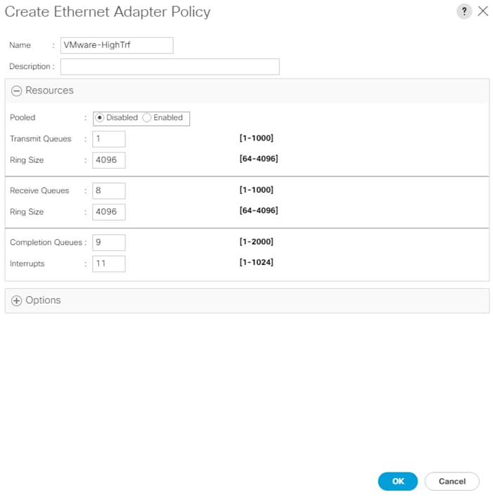
![]() In this policy, Receive Queues can be set to 1-16. Completion Queues = Transmit Queues + Receive Queues. Interrupts = Completion Queues + 2. For more information, see: https://www.cisco.com/c/en/us/products/collateral/interfaces-modules/unified-computing-system-adapters/white-paper-c11-744754.html.
In this policy, Receive Queues can be set to 1-16. Completion Queues = Transmit Queues + Receive Queues. Interrupts = Completion Queues + 2. For more information, see: https://www.cisco.com/c/en/us/products/collateral/interfaces-modules/unified-computing-system-adapters/white-paper-c11-744754.html.
6. Expand Options and choose Enabled for Receive Side Scaling (RSS).
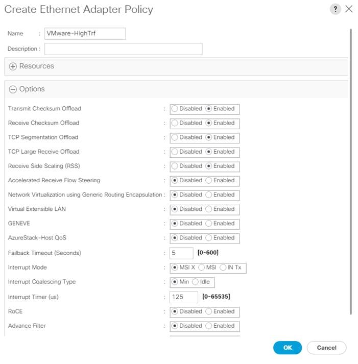
7. Click OK, then click OK again to complete creating the Ethernet Adapter Policy.
Create LAN Connectivity Policy for FC Boot (FCP)
To configure the necessary Infrastructure LAN Connectivity Policy within the FlexPod organization, follow these steps:
1. In Cisco UCS Manager, click LAN.
2. Expand LAN > Policies > root > Sub-Organizations > FlexPod.
3. Under the FlexPod Organization, right-click LAN Connectivity Policies.
4. Choose Create LAN Connectivity Policy.
5. Enter FCP-Boot as the name of the policy.
6. Click Add to add a vNIC.
7. In the Create vNIC dialog box, enter 00-vSwitch0-A as the name of the vNIC.
8. Check the box for Use vNIC Template.
9. In the vNIC Template list, choose vSwitch0-A.
10. In the Adapter Policy list, choose VMWare.
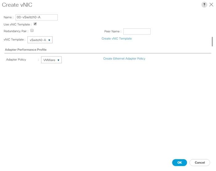
11. Click OK to add this vNIC to the policy.
12. Click Add to add another vNIC to the policy.
13. In the Create vNIC box, enter 01-vSwitch0-B as the name of the vNIC.
14. Check the box for the Use vNIC Template.
15. In the vNIC Template list, choose vSwitch0-B.
16. In the Adapter Policy list, choose VMWare.
17. Click OK to add the vNIC to the policy.
18. Click Add to add another vNIC to the policy.
19. In the Create vNIC dialog box, enter 02-vDS0-A as the name of the vNIC.
20. Check the box for Use vNIC Template.
21. In the vNIC Template list, choose vDS0-A.
22. In the Adapter Policy list, choose VMWare-HighTrf.
![]() The VMware Adapter Policy can also be selected for this vNIC.
The VMware Adapter Policy can also be selected for this vNIC.
23. Click OK to add this vNIC to the policy.
24. Click Add to add another vNIC to the policy.
25. In the Create vNIC box, enter 03-vDS0-B as the name of the vNIC.
26. Check the box for Use vNIC Template.
27. In the vNIC Template list, choose vDS0-B.
28. In the Adapter Policy list, choose VMWare-HighTrf.
![]() Choose the same Adapter Policy that was selected for 02-Infra-vDS-A.
Choose the same Adapter Policy that was selected for 02-Infra-vDS-A.
29. Click OK to add this vNIC to the policy.
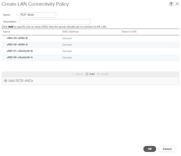
30. Click OK, then click OK again to create the LAN Connectivity Policy.
To configure the necessary server pool for the Cisco UCS environment in the FlexPod Organization, follow these steps:
![]() Consider creating unique server pools to achieve the granularity that is required in your environment.
Consider creating unique server pools to achieve the granularity that is required in your environment.
1. In Cisco UCS Manager, click Servers.
2. Expand Pools > root > Sub-Organizations > FlexPod.
3. Right-click Server Pools under the FlexPod Organization.
4. Choose Create Server Pool.
5. Enter Infra-Pool as the name of the server pool.
6. Optional: Enter a description for the server pool.
7. Click Next.
8. Choose three (or more) servers to be used for the VMware management cluster and click >> to add them to the Infra-Pool server pool.
![]() Although the VMware minimum host cluster size is two, in most use cases three servers are recommended.
Although the VMware minimum host cluster size is two, in most use cases three servers are recommended.
9. Click Finish.
To configure the necessary universally unique identifier (UUID) suffix pool for the Cisco UCS environment, follow these steps:
1. In Cisco UCS Manager, click Servers.
2. Expand Pools > root.
3. Right-click UUID Suffix Pools.
4. Choose Create UUID Suffix Pool.
5. Enter UUID-Pool as the name of the UUID suffix pool.
6. Optional: Enter a description for the UUID suffix pool.
7. Keep the prefix at the derived option.
8. Choose Sequential for the Assignment Order.
9. Click Next.
10. Click Add to add a block of UUIDs.
11. Keep the From field at the default setting.
12. Specify a size for the UUID block that is sufficient to support the available blade or server resources and the number of Service Profiles that will be created.
13. Click OK.
14. Click Finish.
15. Click OK.
Modify Default Host Firmware Package
Firmware management policies allow the administrator to choose the corresponding packages for a given server configuration. These policies often include packages for adapter, BIOS, board controller, FC adapters, host bus adapter (HBA) option ROM, and storage controller properties.
To modify the default firmware management policy in the Cisco UCS environment, follow these steps:
1. In Cisco UCS Manager, click Servers.
2. Expand Policies > root.
3. Expand Host Firmware Packages.
4. Choose default.
5. In the Actions pane, choose Modify Package Versions.
6. Choose version 4.2(1i) for both the Blade and Rack Packages.
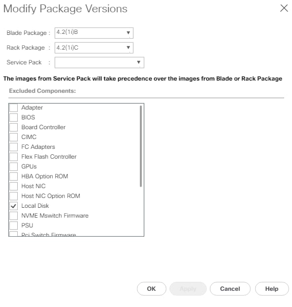
7. Click OK, then click OK again to modify the host firmware package.
Create Local Disk Configuration Policy (Optional)
A local disk configuration specifying no local disks for the Cisco UCS environment can be used to ensure that servers with no local disks are used for SAN Boot.
![]() This policy should not be used on servers that contain local disks.
This policy should not be used on servers that contain local disks.
To create a local disk configuration policy, follow these steps:
1. In Cisco UCS Manager, click Servers.
2. Expand Policies > root.
3. Right-click Local Disk Config Policies.
4. Choose Create Local Disk Configuration Policy.
5. Enter IgnoreDisk as the local disk configuration policy name.
6. Change the mode to Any Configuration.
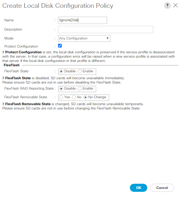
7. Click OK to create the local disk configuration policy.
8. Click OK.
To create a power control policy for the Cisco UCS environment, follow these steps:
1. In Cisco UCS Manager, click Servers.
2. Expand Policies > root.
3. Right-click Power Control Policies.
4. Choose Create Power Control Policy.
5. Enter No-Power-Cap as the power control policy name.
6. Change the power capping setting to No Cap.
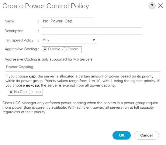
7. Click OK to create the power control policy.
8. Click OK.
Create IPMI Access Profile (Optional)
Intelligent Platform Management Interface (IPMI) is an open standard technology that defines how administrators monitor system hardware and sensors, control system components and retrieve logs of important system events to conduct remote management and recovery. IPMI runs on the BMC (Baseboard Management Controller) of the server and operates independently of the operating system. This profile will assign an IPMI user id and password to the server’s CIMC and will allow the VMware Distributed Power Management (DPM) feature to power on and off ESXi hosts. This feature does typically assign a second IP from the external management or KVM management IP pool to the server. To create an IPMI Access Profile for the Cisco UCS environment, follow these steps:
1. In Cisco UCS Manager, click Servers.
2. Expand Policies > root.
3. Right-click IPMI/Redfish Access Profiles.
4. Choose Create IPMI/Redfish Access Profile.
5. Enter IPMI-Profile as the profile name.
6. Leave IPMI/Redfish Over LAN set to Enable.
7. Click Add to add an IPMI User.
8. Enter ipmiadmin as the user name.
9. Enter and confirm the ipmiadmin password.
10. Set the role to Admin and optionally enter a description for the user.
11. Click OK to add the user.
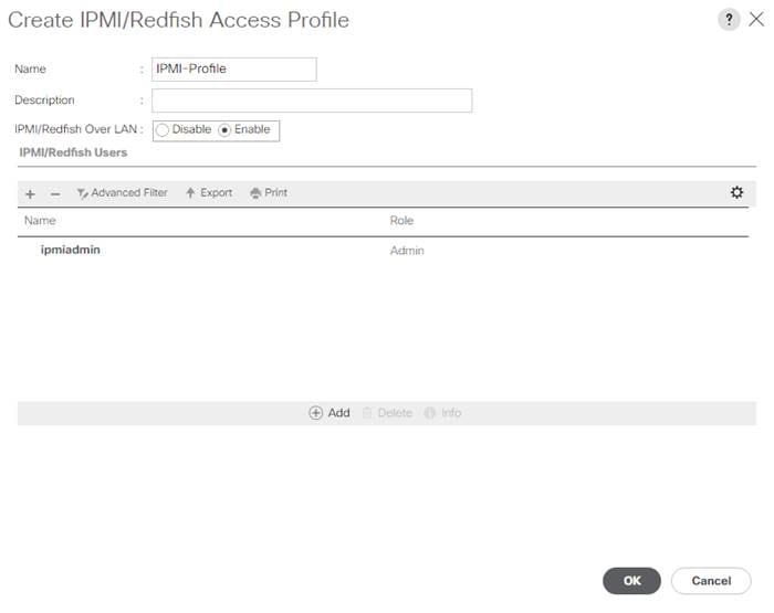
12. Click OK to create the profile.
Create Server Pool Qualification Policy (Optional)
To create an optional server pool qualification policy for the Cisco UCS environment, follow these steps:
![]() This example creates a policy for Cisco UCS B200 M6 servers for a server pool.
This example creates a policy for Cisco UCS B200 M6 servers for a server pool.
1. In Cisco UCS Manager, click Servers.
2. Expand Policies > root.
3. Right-click Server Pool Policy Qualifications.
4. Choose Create Server Pool Policy Qualification.
5. Name the policy UCS-B200M6.
6. Choose Create Server PID Qualifications.
7. Choose UCSB-B200-M6 from the PID drop-down list.
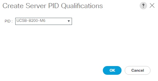
8. Click OK
9. Optionally, choose additional qualifications to refine server selection parameters for the server pool.
10. Click OK to create the policy then OK for the confirmation.
Update the Default Maintenance Policy
To update the default Maintenance Policy to either require user acknowledgement before server boot when service profiles change or to make the changes on the next server reboot, follow these steps:
1. In Cisco UCS Manager, click Servers.
2. Expand Policies > root.
3. Choose Maintenance Policies > default.
4. Change the Reboot Policy to User Ack.
5. Choose “On Next Boot” to delegate maintenance windows to server administrators.
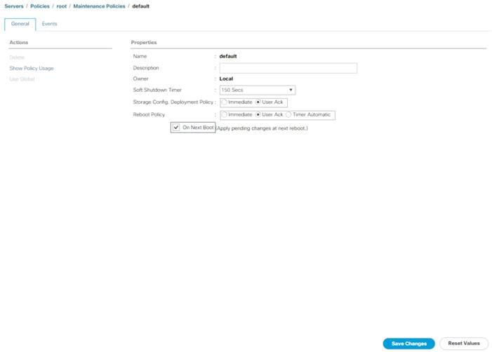
6. Click Save Changes.
7. Click OK to accept the changes.
Create Memory Mode Persistent Memory Policy (Optional)
If any servers in your environment are equipped with Intel Optane DC Persistent Memory (PMEM), a Persistent Memory Policy should be used. Intel Optane DC PMEM can be used in App Direct Mode or Memory Mode with VMware vSphere 7.0 Update 2. In a Cisco UCS server that is equipped with Intel Optane DC PMEM, if a Persistent Memory Policy is not assigned, 100 percent of the Intel Optane DC PMEM will be used in Memory Mode and the standard DIMMs in the server will be used as cache and the DIMM capacity will not be visible. In VMware vSphere 7.0 Update 2, usage of Intel Optane DC PMEM in Memory Mode is supported with certain configurations identified in vSphere Support for Intel's Optane Persistent Memory (PMEM) (67645). If you have Intel Optane DC PMEM installed in any of your servers in a configuration identified in the KB, Memory Mode is supported with VMware vSphere 7.0 Update 2. If you have Intel Optane DC PMEM installed in a server, but not in one of the supported configurations, you should use App Direct Mode.
To create a memory mode persistent memory policy, follow these steps:
1. In Cisco UCS Manager, choose Servers.
2. Expand Policies > root.
3. Right-click Persistent Memory Policy.
4. Choose Create Persistent Memory Policy.
5. Name the policy Memory-Mode.
6. Under Goals, click Add.
7. Set Memory Mode (%) to 100 and set Persistent Memory Type to App Direct.
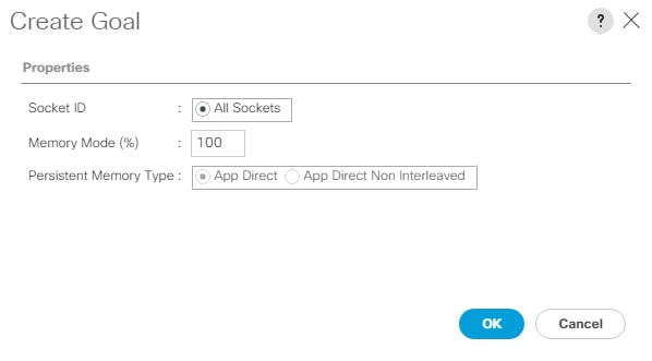
8. Click OK to complete creating the Goal.
9. Click OK to complete creating the policy and click OK on the confirmation.
Create App Direct Mode Persistent Memory Policy (Optional)
If you have Intel Optane DC PMEM installed in a server, but not in one of the supported configurations for Memory Mode, you should use App Direct Mode. You can also use App Direct Mode with any 3rd party application that supports it.
To create an app direct mode persistent memory policy, follow these steps:
1. In Cisco UCS Manager, choose Servers.
2. Expand Policies > root.
3. Right-click Persistent Memory Policy.
4. Choose Create Persistent Memory Policy.
5. Name the policy App-Direct-Mode.
6. Under Goals, click Add.
7. Leave Memory Mode (%) set to zero and Persistent Memory Type set to App Direct.
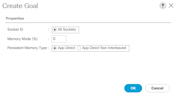
8. Click OK to complete creating the Goal.
9. Click OK to complete creating the policy and click OK on the confirmation.
![]() VMware does not support mixed mode (partially Memory Mode and partially App Direct Mode) persistent memory policies.
VMware does not support mixed mode (partially Memory Mode and partially App Direct Mode) persistent memory policies.
Create vMedia Policy for VMware ESXi 7.0 ISO Install Boot
In the NetApp ONTAP setup steps, an HTTP web server is required, which is used for hosting ONTAP as well as VMware software. The vMedia Policy created will map the Cisco Custom Image for ESXi 7.0 U2 Install CD to the Cisco UCS server in order to boot the ESXi installation. To create this policy, follow these steps:
1. In Cisco UCS Manager, choose Servers.
2. Expand Policies > root.
3. Right-click vMedia Policies.
4. Choose Create vMedia Policy.
5. Name the policy ESXi-7U2-CC-HTTP.
6. Enter “Mounts Cisco Custom ISO for ESXi7.0U2” in the Description field.
7. Click Add to add a vMedia Mount.
8. Name the mount ESXi-7U2-CC-HTTP.
9. Choose the CDD Device Type.
10. Choose the HTTP Protocol.
11. Enter the IP Address of the web server.
![]() To avoid any DNS lookup issues, enter the IP of the web server instead of the hostname.
To avoid any DNS lookup issues, enter the IP of the web server instead of the hostname.
12. Enter VMware_ESXi_7.0.2_17867351_Custom_Cisco_4.1.3_a.iso as the Remote File name.
![]() This VMware ESXi 7.0U2 Cisco Custom ISO can be downloaded from VMware Downloads.
This VMware ESXi 7.0U2 Cisco Custom ISO can be downloaded from VMware Downloads.
![]() If a working vCenter 7.0U2 installation is already in your environment, a FlexPod custom ISO for installing ESXi 7.0U2 with all necessary drivers for this FlexPod deployment can be created. Please see Create a FlexPod ESXi Custom ISO using VMware vCenter for a procedure for building this custom ISO.
If a working vCenter 7.0U2 installation is already in your environment, a FlexPod custom ISO for installing ESXi 7.0U2 with all necessary drivers for this FlexPod deployment can be created. Please see Create a FlexPod ESXi Custom ISO using VMware vCenter for a procedure for building this custom ISO.
13. Enter the web server path to the ISO file in the Remote Path field.
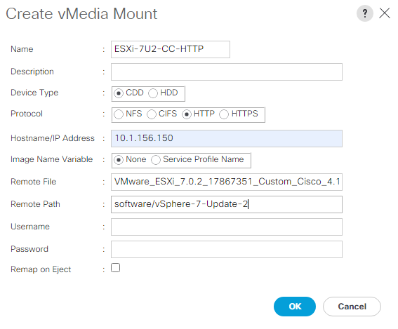
14. Click OK to create the vMedia Mount.
15. Click OK then click OK again to complete creating the vMedia Policy.
![]() For any new servers added to the Cisco UCS environment the vMedia service profile template can be used to install the ESXi host. On first boot the host will boot into the ESXi installer since the SAN mounted disk is empty. After ESXi is installed, the vMedia will not be referenced as long as the boot disk is accessible.
For any new servers added to the Cisco UCS environment the vMedia service profile template can be used to install the ESXi host. On first boot the host will boot into the ESXi installer since the SAN mounted disk is empty. After ESXi is installed, the vMedia will not be referenced as long as the boot disk is accessible.
To create server BIOS policies for VMware ESXi hosts within the FlexPod organization, follow these steps:
![]() In this lab validation, the Cisco UCS B200 M6 servers had TPM2.0 modules installed. To utilize TPM2.0 functionality with VMware vSphere 7.0U2, the TPM module must be enabled, and Trusted Execution Technology (TXT) disabled in BIOS. According to the Cisco UCS Server BIOS Tokens, Release 4.1 document, which is referenced from Cisco UCS Server BIOS Tokens, Release 4.2, these settings are the default or Platform Default settings for all M5 and M6 servers. Because of this, these settings do not have to be added to this BIOS policy. Three BIOS policies will be created.
In this lab validation, the Cisco UCS B200 M6 servers had TPM2.0 modules installed. To utilize TPM2.0 functionality with VMware vSphere 7.0U2, the TPM module must be enabled, and Trusted Execution Technology (TXT) disabled in BIOS. According to the Cisco UCS Server BIOS Tokens, Release 4.1 document, which is referenced from Cisco UCS Server BIOS Tokens, Release 4.2, these settings are the default or Platform Default settings for all M5 and M6 servers. Because of this, these settings do not have to be added to this BIOS policy. Three BIOS policies will be created.
1. In Cisco UCS Manager, click Servers.
2. Expand Policies > root.
3. Right-click BIOS Policies under the root Organization.
4. Choose Create BIOS Policy.
5. Enter Intel-M6-Virt as the BIOS policy name.
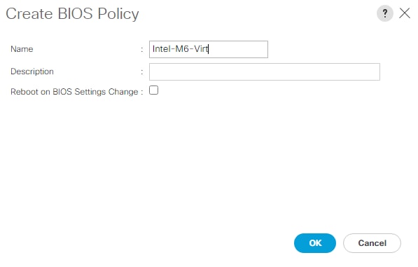
6. Click OK, then click OK again to create the BIOS Policy.
![]() The Intel-M6-Virt BIOS Policy is derived from the virtualization policy in Performance Tuning Guide for Cisco UCS M6 Servers with the addition of CDN Control and NVM Performance Setting.
The Intel-M6-Virt BIOS Policy is derived from the virtualization policy in Performance Tuning Guide for Cisco UCS M6 Servers with the addition of CDN Control and NVM Performance Setting.
7. Under the FlexPod Organization, expand BIOS Policies and choose the newly created BIOS Policy. Within the Main tab of the Policy, set the following:
a. CDN Control > Enabled
b. Quiet Boot > Disabled
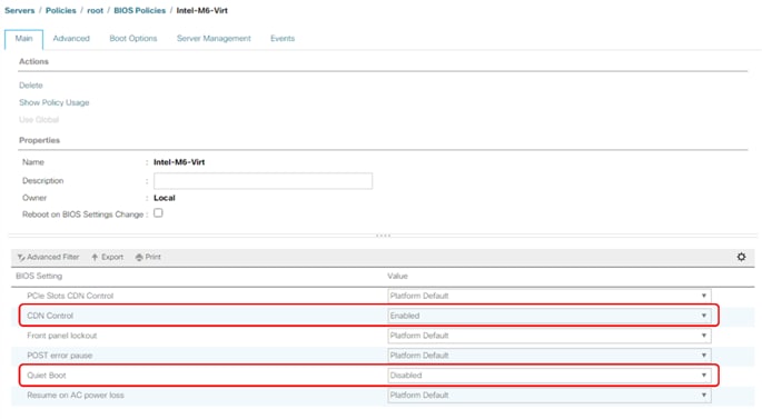
8. Click the Advanced tab, leaving the Processor tab selected within the Advanced tab. Within the Processor tab, set the following:
a. Enhanced CPU Performance > Auto
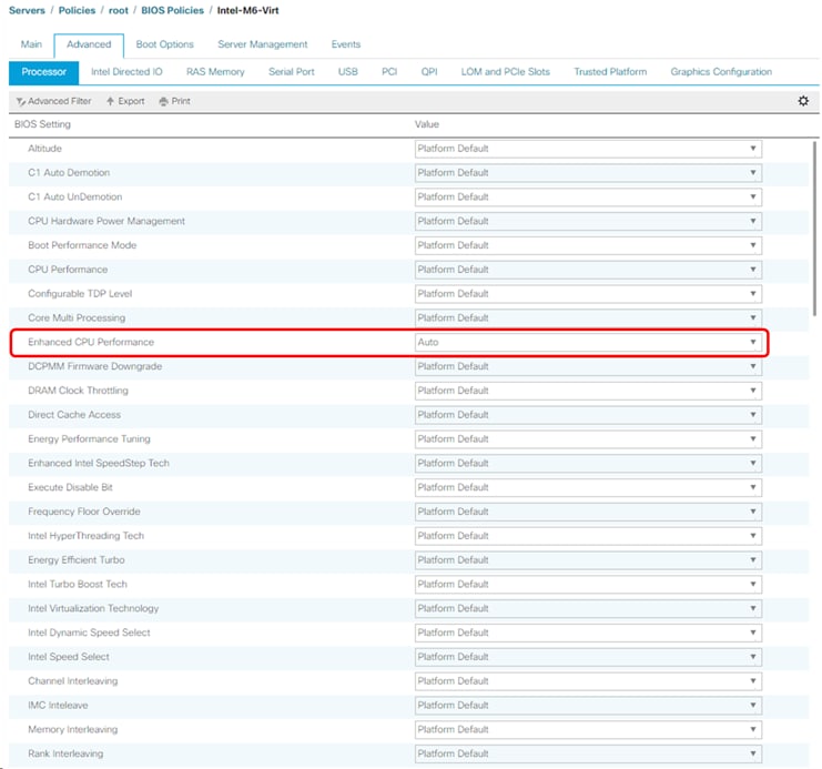
9. Click Save Changes.
10. Click OK.
11. Click the RAS Memory tab within the Advanced tab. Within the RAS Memory tab, set the following:
a. NVM Performance Setting > Balanced Profile
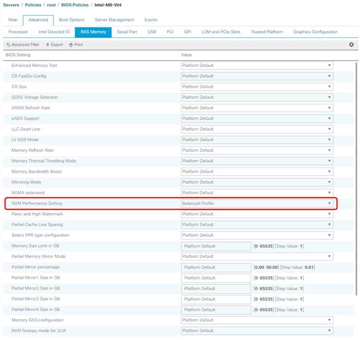
12. Click Save Changes.
13. Click OK.
14. In Cisco UCS Manager, click Servers.
15. Expand Policies > root.
16. Right-click BIOS Policies under the root Organization.
17. Choose Create BIOS Policy.
18. Enter Intel-M5-Virt as the BIOS policy name.
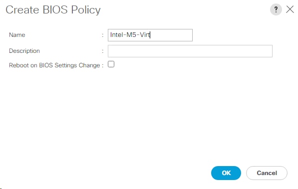
19. Click OK, then click OK again to create the BIOS Policy.
![]() The Intel-M5-Virt BIOS Policy is derived from the virtualization policy in Performance Tuning Guide for Cisco UCS M5 Servers White Paper with the addition of CDN Control and NVM Performance Setting.
The Intel-M5-Virt BIOS Policy is derived from the virtualization policy in Performance Tuning Guide for Cisco UCS M5 Servers White Paper with the addition of CDN Control and NVM Performance Setting.
20. Under the FlexPod Organization, expand BIOS Policies and choose the newly created BIOS Policy. Within the Main tab of the Policy, set the following:
a. CDN Control > Enabled
b. Quiet Boot > Disabled
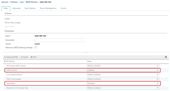
21. Click the Advanced tab, leaving the Processor tab selected within the Advanced tab. Within the Processor tab, set the following:
a. Processor C State > Disabled
b. Processor C1E > Disabled
c. Processor C3 Report > Disabled
d. Processor C6 Report > Disabled
e. Processor C7 Report > Disabled
f. Power Technology > Custom
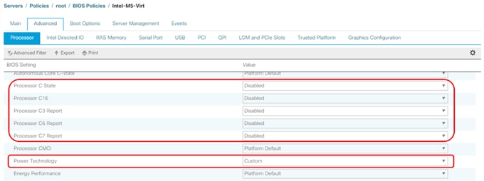
22. Click Save Changes.
23. Click OK.
24. Click the RAS Memory tab within the Advanced tab. Within the RAS Memory tab, set the following:
a. NVM Performance Setting > Balanced Profile
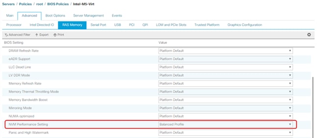
25. Click Save Changes.
26. Click OK.
27. In Cisco UCS Manager, click Servers.
28. Expand Policies > root.
29. Right-click BIOS Policies under the root Organization.
30. Choose Create BIOS Policy.
31. Enter AMD-C125-Virt as the BIOS policy name.

32. Click OK, then click OK again to create the BIOS Policy.
![]() The AMD-C125-Virt BIOS Policy is derived from the virtualization policy in Performance Tuning for Cisco UCS C125 Rack Server Nodes with AMD Processors (White Paper) with the addition of CDN Control.
The AMD-C125-Virt BIOS Policy is derived from the virtualization policy in Performance Tuning for Cisco UCS C125 Rack Server Nodes with AMD Processors (White Paper) with the addition of CDN Control.
33. Under the FlexPod Organization, expand BIOS Policies and choose the newly created BIOS Policy. Within the Main tab of the Policy, set the following:
a. CDN Control > Enabled
b. Quiet Boot > Disabled
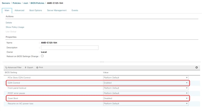
34. Click the Advanced tab, leaving the Processor tab selected within the Advanced tab. Within the Processor tab, set the following:
a. Determinism Slider > Power
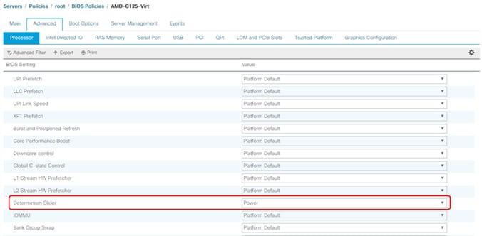
35. Click Save Changes.
36. Click OK.
Create FC Boot Policy (FCP)
This procedure applies to a Cisco UCS environment in which two Fibre Channel logical interfaces (LIFs) are on cluster node 1 (fcp-lif-01a and fcp-lif-01b) and two Fibre Channel LIFs are on cluster node 2 (fcp-lif-02a and fcp-lif-02b). Also, it is assumed that the A LIFs are connected to switching Fabric A and the B LIFs are connected to switching Fabric B.
![]() One boot policy is configured in this procedure. The policy configures the primary target to be fcp-lif-01a.
One boot policy is configured in this procedure. The policy configures the primary target to be fcp-lif-01a.
To create a boot policy for the within the FlexPod organization, follow these steps:
1. In Cisco UCS Manager, click Servers.
2. Expand Policies > root > Sub-Organizations > FlexPod.
3. Under the FlexPod Organization, right-click Boot Policies.
4. Choose Create Boot Policy.
5. Enter Boot-FCP as the name of the boot policy.
6. Optional: Enter a description for the boot policy.
7. Do not select the Reboot on Boot Order Change checkbox.
8. Choose the Uefi Boot Mode.
9. Check the box for Boot Security.

![]() UEFI Secure Boot can be used to boot VMware ESXi 7.0 with or without a TPM 2.0 module in the UCS server.
UEFI Secure Boot can be used to boot VMware ESXi 7.0 with or without a TPM 2.0 module in the UCS server.
10. Expand Local Devices and choose Add Remote CD/DVD.
11. Expand vHBAs and choose Add SAN Boot.
12. Choose Primary in the Type field.
13. Enter FCP-Fabric-A in the vHBA field.
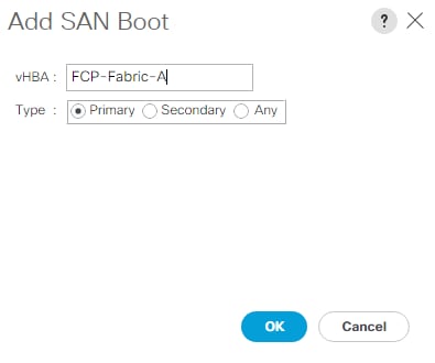
14. Click OK.
15. From vHBAs, choose Add SAN Boot Target.
16. Keep 0 as the value for Boot Target LUN.
17. Enter the WWPN for fcp-lif-01a.
![]() To obtain this information, log in to the storage cluster and run the network interface show -vserver Infra-SVM command.
To obtain this information, log in to the storage cluster and run the network interface show -vserver Infra-SVM command.
18. Choose Primary for the SAN boot target type.
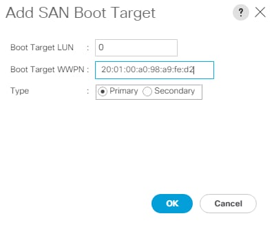
19. Click OK to add the SAN boot target.
20. From vHBAs, choose Add SAN Boot Target.
21. Enter 0 as the value for Boot Target LUN.
22. Enter the WWPN for fcp-lif-02a.
23. Click OK to add the SAN boot target.
24. From vHBAs, choose Add SAN Boot.
25. In the Add SAN Boot dialog box, enter FCP-Fabric-B in the vHBA box.
26. The SAN boot type should automatically be set to Secondary.
27. Click OK.
28. From vHBAs, choose Add SAN Boot Target.
29. Keep 0 as the value for Boot Target LUN.
30. Enter the WWPN for fcp-lif-01b.
31. Choose Primary for the SAN boot target type.
32. Click OK to add the SAN boot target.
33. From vHBAs, choose Add SAN Boot Target.
34. Keep 0 as the value for Boot Target LUN.
35. Enter the WWPN for fcp-lif-02b.
36. Click OK to add the SAN boot target.
37. Expand CIMC Mounted Media and choose Add CIMC Mounted CD/DVD.
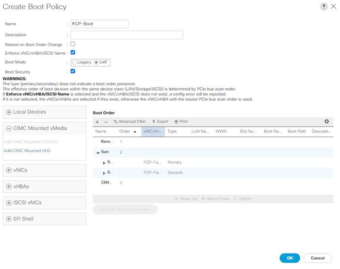
38. Expand San > SAN Primary and select SAN Target Primary. Select Set Uefi Boot Parameters.
![]() For Cisco UCS M6 and M5 servers it is not necessary to set the Uefi Boot Parameters. These servers will boot properly with or without these parameters set. However, for M4 and earlier servers, VMware ESXi 7.0 and above will not boot with Uefi Secure Boot unless these parameters are set exactly as shown.
For Cisco UCS M6 and M5 servers it is not necessary to set the Uefi Boot Parameters. These servers will boot properly with or without these parameters set. However, for M4 and earlier servers, VMware ESXi 7.0 and above will not boot with Uefi Secure Boot unless these parameters are set exactly as shown.
39. Enter the Set Uefi Boot Parameters exactly as shown in the following screenshot:
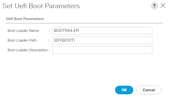
40. Click OK to complete setting the Uefi Boot Parameters for the SAN Boot Target and click OK for the confirmation.
41. Repeat steps 1 - 10 to set Uefi Boot Parameters for each of the 4 SAN Boot Targets.
42. Click OK, then click OK again to create the boot policy.
Create Service Profile Template (FCP)
In this procedure, one service profile template for Infrastructure ESXi hosts is created for Fabric A boot within the FlexPod organization. To create the service profile template, follow these steps:
1. In Cisco UCS Manager, click Servers.
2. Expand Service Profile Templates > root > Sub-Organizations > FlexPod.
3. Right-click the FlexPod Organization.
4. Choose Create Service Profile Template to open the Create Service Profile Template wizard.
5. Enter VM-Host-Infra-FCP as the name of the service profile template.
6. Choose the Updating Template option.
7. Under UUID, choose UUID_Pool as the UUID pool.
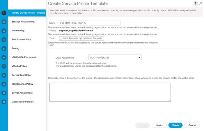
8. Click Next.
Configure Storage Provisioning
To configure storage provisioning, follow these steps:
1. Under the Local Disk Configuration Policy tab choose the IgnoreDisk Local Storage Policy.
2. Click Next.
To configure networking, follow these steps:
1. Choose the “Use Connectivity Policy” option to configure the LAN connectivity.
2. Choose FCP-Boot from the LAN Connectivity Policy drop-down list.
3. Leave Initiator Name Assignment at <not set>.
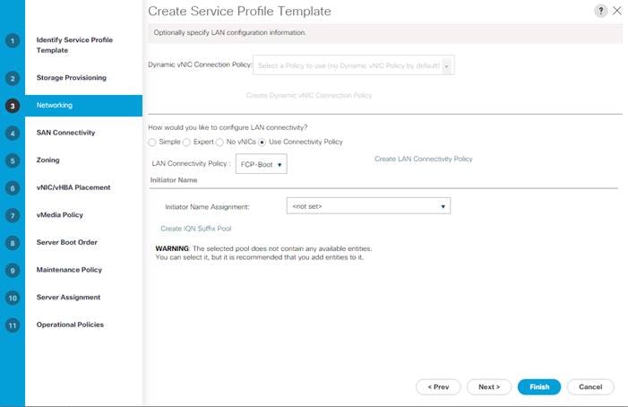
4. Click Next.
To configure SAN connectivity, follow these steps:
1. Choose the Use Connectivity Policy option for the “How would you like to configure SAN connectivity?” field.
2. Choose the FC-Boot option from the SAN Connectivity Policy drop-down list.
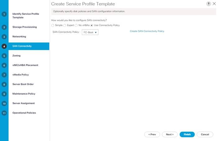
3. Click Next.
To configure zoning, follow this step:
1. Set no zoning options and click Next.
![]() Set no zoning options here since the fabric interconnects are in end host (NPV) mode and zoning is being done in the upstream SAN switch.
Set no zoning options here since the fabric interconnects are in end host (NPV) mode and zoning is being done in the upstream SAN switch.
To configure vNIC/HBA placement, follow these steps:
1. In the Select Placement list, retain the placement policy as Let System Perform Placement.
2. Click Next.
To configure the vMedia policy, follow these steps:
1. Do not select a vMedia Policy.
2. Click Next.
To configure the server boot order, follow these steps:
1. Choose Boot-FCP for Boot Policy.
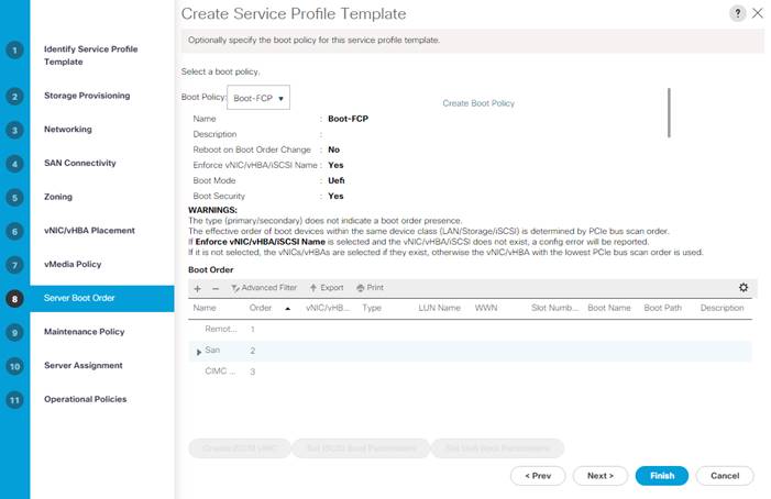
2. Click Next.
To configure the maintenance policy, follow these steps:
1. Change the Maintenance Policy to default.
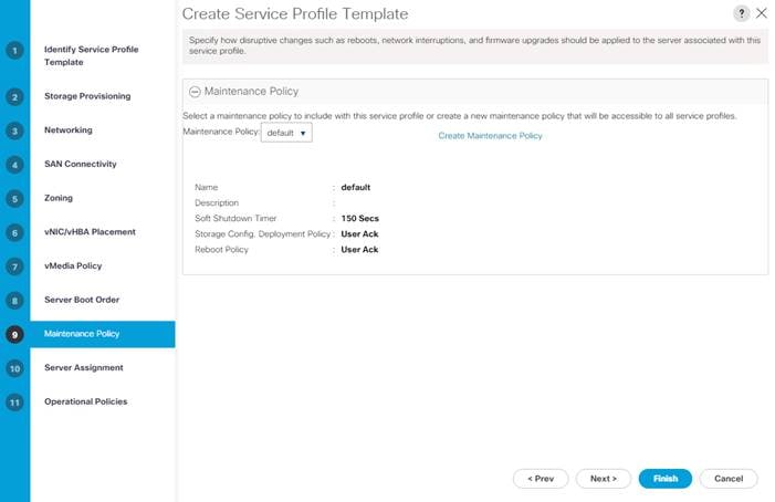
2. Click Next.
To configure server assignment, follow these steps:
1. In the Pool Assignment list, choose Infra-Pool.
2. Choose Down as the power state to be applied when the profile is associated with the server.
3. Optional: Choose “UCS-B200M6” for the Server Pool Qualification to choose only UCS B200M6 servers in the pool.
4. Expand Firmware Management and choose the default Host Firmware Package.
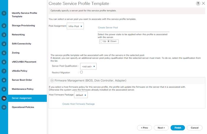
5. Click Next.
Configure Operational Policies
To configure the operational policies, follow these steps:
1. In the BIOS Policy list, choose the appropriate BIOS policy for the servers you have.
2. Expand External IPMI/Redfish Management Configuration and select IPMI-Profile for the IPMI/Redfish Access Profile.
3. Expand Power Control Policy Configuration and choose No-Power-Cap in the Power Control Policy list.

4. Click Finish to create the service profile template.
5. Click OK in the confirmation message.
Create vMedia-Enabled Service Profile Template
To create a service profile template with vMedia enabled, follow these steps:
1. Connect to UCS Manager and click Servers.
2. Choose Service Profile Templates > root > Sub-Organizations > FlexPod > Service Template VM-Host-Infra-FCP.
3. Right-click VM-Host-Infra-FCP and choose Create a Clone.
4. Name the clone VM-Host-Infra-FCP -vM.
5. Click OK then click OK again to create the Service Profile Template clone.
6. Choose the newly created VM-Host-Infra-FCP -vM and choose the vMedia Policy tab.
7. Click Modify vMedia Policy.
8. Choose the ESXi-7U2-CC-HTTP vMedia Policy and click OK.
9. Click OK to confirm.
This same cloning process can be used to create other Service Profile templates that can be modified to accommodate additional features such as Intel Datacenter Persistent Memory (DCPMem) in Memory or App-Direct Mode.
To create service profiles from the service profile template within the FlexPod organization, follow these steps:
1. Connect to Cisco UCS Manager and click Servers.
2. Expand Service Profile Templates > root > Sub-Organizations > FlexPod.
3. Right-click the appropriate vMedia-enabled template or the appropriate template and choose Create Service Profiles from Template.
4. Enter VM-Host-Infra-0 as the service profile prefix.
5. Enter 1 as “Name Suffix Starting Number.”
6. Enter 3 as the “Number of Instances.”
7. Click OK to create the service profiles.
8. Click OK in the confirmation message.
9. When VMware ESXi 7.0U2 has been installed on the hosts, the host Service Profiles can be bound to the corresponding non-vMedia-enabled Service Profile Template to remove the vMedia Mapping from the host.
Add More Servers to FlexPod Unit
Additional server pools, service profile templates, and service profiles can be created in the respective organizations to add more servers to the FlexPod unit. All pools and policies created at the organizational level will need to be recreated within other organizations.
After the Cisco UCS service profiles have been created, each infrastructure server in the environment will have a unique configuration. To proceed with the FlexPod deployment, specific information must be gathered from each Cisco UCS server and from the NetApp controllers.
Table 6. WWPNs from NetApp Storage
| SVM |
Adapter |
MDS Switch |
Target: WWPN |
| Infra_SVM |
fcp-lif-01a |
Fabric A |
<fcp-lif-01a-wwpn> |
| fcp-lif-01b |
Fabric B |
<fcp-lif-01b-wwpn> |
|
| fcp-lif-02a |
Fabric A |
<fcp-lif-02a-wwpn> |
|
| fcp-lif-02b |
Fabric B |
<fcp-lif-02b-wwpn> |
![]() To obtain the FC WWPNs, run the network interface show command on the storage cluster management interface.
To obtain the FC WWPNs, run the network interface show command on the storage cluster management interface.
Table 7. WWPNs for Cisco UCS Service Profiles
| Cisco UCS Service Profile Name |
MDS Switch |
Initiator WWPN |
| VM-Host-Infra-01 |
Fabric A |
<vm-host-infra-01-wwpna> |
| Fabric B |
<vm-host-infra-01-wwpnb> |
|
| Fabric A |
<vm-host-infra-02-wwpna> |
|
| Fabric B |
<vm-host-infra-02-wwpnb> |
|
| VM-Host-Infra-03 |
Fabric A |
<vm-host-infra-03-wwpna> |
| Fabric B |
<vm-host-infra-03-wwpnb> |
![]() To obtain the FC vHBA WWPN information in Cisco UCS Manager GUI, go to Servers > Service Profiles > root > Sub-Organizations > Organization. Expand each service profile and then expand vHBAs. Select each vHBA. The WWPN is shown under Properties.
To obtain the FC vHBA WWPN information in Cisco UCS Manager GUI, go to Servers > Service Profiles > root > Sub-Organizations > Organization. Expand each service profile and then expand vHBAs. Select each vHBA. The WWPN is shown under Properties.
This section explains how to configure the Cisco MDS 9000s for use in a FlexPod environment. Follow the steps precisely because failure to do so could result in an improper configuration.
![]() If using the Cisco Nexus 93180YC-FX for both LAN and SAN switching, please refer to FlexPod with Nexus 93180YC-FX SAN Switching Configuration – Part 2 in the Appendix.
If using the Cisco Nexus 93180YC-FX for both LAN and SAN switching, please refer to FlexPod with Nexus 93180YC-FX SAN Switching Configuration – Part 2 in the Appendix.
![]() If directly connecting storage to the Cisco UCS fabric interconnects or using iSCSI as the boot protocol, skip this section.
If directly connecting storage to the Cisco UCS fabric interconnects or using iSCSI as the boot protocol, skip this section.
Physical Connectivity
Follow the physical connectivity guidelines for FlexPod as explained in section FlexPod Cabling.
FlexPod Cisco MDS Base
The following procedures describe how to configure the Cisco Nexus switches for use in a base FlexPod environment. This procedure assumes you are using the Cisco MDS 9132T with NX-OS 8.4(2c).
Cisco MDS 9132T A
To set up the initial configuration for the Cisco MDS A switch, <mds-A-hostname>, follow these steps:
![]() On initial boot and connection to the serial or console port of the switch, the NX-OS setup should automatically start and attempt to enter Power on Auto Provisioning. Enter y to get to the System Admin Account Setup.
On initial boot and connection to the serial or console port of the switch, the NX-OS setup should automatically start and attempt to enter Power on Auto Provisioning. Enter y to get to the System Admin Account Setup.
1. Configure the switch using the command line.
---- System Admin Account Setup ----
Do you want to enforce secure password standard (yes/no) [y]: Enter
Enter the password for "admin": <password>
Confirm the password for "admin": <password>
Would you like to enter the basic configuration dialog (yes/no): yes
Create another login account (yes/no) [n]: Enter
Configure read-only SNMP community string (yes/no) [n]: Enter
Configure read-write SNMP community string (yes/no) [n]: Enter
Enter the switch name : <mds-A-hostname>
Continue with Out-of-band (mgmt0) management configuration? (yes/no) [y]: Enter
Mgmt0 IPv4 address : <mds-A-mgmt0-ip>
Mgmt0 IPv4 netmask : <mds-A-mgmt0-netmask>
Configure the default gateway? (yes/no) [y]: Enter
IPv4 address of the default gateway : <mds-A-mgmt0-gw>
Configure advanced IP options? (yes/no) [n]: Enter
Enable the ssh service? (yes/no) [y]: Enter
Type of ssh key you would like to generate (dsa/rsa) [rsa]: Enter
Number of rsa key bits <1024-2048> [1024]: Enter
Enable the telnet service? (yes/no) [n]: Enter
Configure congestion/no_credit drop for fc interfaces? (yes/no) [y]: Enter
Enter the type of drop to configure congestion/no_credit drop? (con/no) [c]: Enter
Enter milliseconds in multiples of 10 for congestion-drop for logical-type edge
in range (<200-500>/default), where default is 500. [d]: Enter
Enable the http-server? (yes/no) [y]: Enter
Configure clock? (yes/no) [n]: Enter
Configure timezone? (yes/no) [n]: Enter
Configure summertime? (yes/no) [n]: Enter
Configure the ntp server? (yes/no) [n]: Enter
Configure default switchport interface state (shut/noshut) [shut]: Enter
Configure default switchport trunk mode (on/off/auto) [on]: auto
Configure default switchport port mode F (yes/no) [n]: yes
Configure default zone policy (permit/deny) [deny]: Enter
Enable full zoneset distribution? (yes/no) [n]: Enter
Configure default zone mode (basic/enhanced) [basic]: Enter
2. Review the configuration.
Would you like to edit the configuration? (yes/no) [n]: Enter
Use this configuration and save it? (yes/no) [y]: Enter
Cisco MDS 9132T B
To set up the initial configuration for the Cisco MDS B switch, <mds-B-hostname>, follow these steps:
![]() On initial boot and connection to the serial or console port of the switch, the NX-OS setup should automatically start and attempt to enter Power on Auto Provisioning. Enter y to get to the System Admin Account Setup.
On initial boot and connection to the serial or console port of the switch, the NX-OS setup should automatically start and attempt to enter Power on Auto Provisioning. Enter y to get to the System Admin Account Setup.
1. Configure the switch using the command line.
---- System Admin Account Setup ----
Do you want to enforce secure password standard (yes/no) [y]: Enter
Enter the password for "admin": <password>
Confirm the password for "admin": <password>
Would you like to enter the basic configuration dialog (yes/no): yes
Create another login account (yes/no) [n]: Enter
Configure read-only SNMP community string (yes/no) [n]: Enter
Configure read-write SNMP community string (yes/no) [n]: Enter
Enter the switch name : <mds-B-hostname>
Continue with Out-of-band (mgmt0) management configuration? (yes/no) [y]: Enter
Mgmt0 IPv4 address : <mds-B-mgmt0-ip>
Mgmt0 IPv4 netmask : <mds-B-mgmt0-netmask>
Configure the default gateway? (yes/no) [y]: Enter
IPv4 address of the default gateway : <mds-B-mgmt0-gw>
Configure advanced IP options? (yes/no) [n]: Enter
Enable the ssh service? (yes/no) [y]: Enter
Type of ssh key you would like to generate (dsa/rsa) [rsa]: Enter
Number of rsa key bits <1024-2048> [1024]: Enter
Enable the telnet service? (yes/no) [n]: Enter
Configure congestion/no_credit drop for fc interfaces? (yes/no) [y]: Enter
Enter the type of drop to configure congestion/no_credit drop? (con/no) [c]: Enter
Enter milliseconds in multiples of 10 for congestion-drop for logical-type edge
in range (<200-500>/default), where default is 500. [d]: Enter
Enable the http-server? (yes/no) [y]: Enter
Configure clock? (yes/no) [n]: Enter
Configure timezone? (yes/no) [n]: Enter
Configure summertime? (yes/no) [n]: Enter
Configure the ntp server? (yes/no) [n]: Enter
Configure default switchport interface state (shut/noshut) [shut]: Enter
Configure default switchport trunk mode (on/off/auto) [on]: auto
Configure default switchport port mode F (yes/no) [n]: yes
Configure default zone policy (permit/deny) [deny]: Enter
Enable full zoneset distribution? (yes/no) [n]: Enter
Configure default zone mode (basic/enhanced) [basic]: Enter
2. Review the configuration.
Would you like to edit the configuration? (yes/no) [n]: Enter
Use this configuration and save it? (yes/no) [y]: Enter
FlexPod Cisco MDS Ansible Switch Configuration
The following procedure can be used to configure the Cisco MDS switches from the management workstation.
1. Add MDS switch ssh keys to /root/.ssh/known_hosts. Adjust known_hosts as necessary if errors occur.
ssh admin@<mds-A-mgmt0-ip>
exit
ssh admin@<mds-B-mgmt0-ip>
exit
2. Edit the following variable files to ensure proper MDS variables are entered:
● FlexPod-M6/FlexPod-UCSM-M6/inventory
● FlexPod-M6/FlexPod-UCSM-M6/group_vars/all.yml
● FlexPod-M6/FlexPod-UCSM-M6/host_vars/mdsA.yml
● FlexPod-M6/FlexPod-UCSM-M6/host_vars/mdsB.yml
● FlexPod-M6/FlexPod-UCSM-M6/roles/MDSconfig/defaults/main.yml
![]() The FC and FC-NVMe NetApp LIF WWPNs should have already been entered into the all.yml file so that MDS device alias can be properly configured. The Cisco UCS server initiator WWPNs for both FC and FC-NVMe should also be entered into all.yml. To query these WWPNs, log into the Cisco UCS Manager web interface and select each of the 3 server service profiles by going to “Servers > Service Profiles > root > Sub-Organizations > FlexPod Organization” and expanding the service profile. The needed WWPNs can be found by expanding vHBAs and selecting each vHBA.
The FC and FC-NVMe NetApp LIF WWPNs should have already been entered into the all.yml file so that MDS device alias can be properly configured. The Cisco UCS server initiator WWPNs for both FC and FC-NVMe should also be entered into all.yml. To query these WWPNs, log into the Cisco UCS Manager web interface and select each of the 3 server service profiles by going to “Servers > Service Profiles > root > Sub-Organizations > FlexPod Organization” and expanding the service profile. The needed WWPNs can be found by expanding vHBAs and selecting each vHBA.
3. From /root/ FlexPod-M6/FlexPod-UCSM-M6, run the Setup_MDS.yml Ansible playbook.
ansible-playbook ./Setup_MDS.yml -i inventory
4. Once the Ansible playbook has been run and configured both switches, it is important to configure the local time so that logging time alignment and any backup schedules are correct. For more information on configuring the timezone and daylight savings time or summertime, please see Cisco MDS 9000 Series Fundamentals Configuration Guide, Release 8.x. Sample clock commands for the United States Eastern timezone are:
clock timezone EST -5 0
clock summer-time EDT 2 Sunday March 02:00 1 Sunday November 02:00 60
5. ssh into each switch and execute the following commands
clock timezone <timezone> <hour-offset> <minute-offset>
clock summer-time <timezone> <start-week> <start-day> <start-month> <start-time> <end-week> <end-day> <end-month> <end-time> <offset-minutes>
FlexPod Cisco MDS Switch Manual Configuration
Cisco MDS 9132T A and Cisco MDS 9132T B
To enable the correct features on the Cisco MDS switches, follow these steps:
1. Log in as admin.
2. Run the following commands:
configure terminal
feature npiv
feature fport-channel-trunk
Add NTP Servers and Local Time Configuration
Cisco MDS 9132T A and Cisco MDS 9132T B
To configure the second NTP server and add local time configuration, follow this step:
1. From the global configuration mode, run the following command:
ntp server <nexus-A-mgmt0-ip>
ntp server <nexus-B-mgmt0-ip>
clock timezone <timezone> <hour-offset> <minute-offset>
clock summer-time <timezone> <start-week> <start-day> <start-month> <start-time> <end-week> <end-day> <end-month> <end-time> <offset-minutes>
![]() It is important to configure the local time so that logging time alignment, any backup schedules, and SAN Analytics forwarding are correct. For more information on configuring the timezone and daylight savings time or summer time, please see Cisco MDS 9000 Series Fundamentals Configuration Guide, Release 8.x. Sample clock commands for the United States Eastern timezone are:
It is important to configure the local time so that logging time alignment, any backup schedules, and SAN Analytics forwarding are correct. For more information on configuring the timezone and daylight savings time or summer time, please see Cisco MDS 9000 Series Fundamentals Configuration Guide, Release 8.x. Sample clock commands for the United States Eastern timezone are:
clock timezone EST -5 0
clock summer-time EDT 2 Sunday March 02:00 1 Sunday November 02:00 60
Cisco MDS 9132T A
To configure individual ports and port-channels for switch A, follow this step:
1. From the global configuration mode, run the following commands:
switchport description <st-clustername>-1:5a
switchport speed 32000
switchport trunk mode off
no shutdown
exit
interface fc1/2
switchport description <st-clustername>-2:5a
switchport speed 32000
switchport trunk mode off
no shutdown
exit
interface fc1/5
switchport description <ucs-clustername>-a:1/1
channel-group 15
no shutdown
exit
interface fc1/6
switchport description <ucs-clustername>-a:1/2
channel-group 15
no shutdown
exit
interface port-channel15
channel mode active
switchport trunk allowed vsan <vsan-a-id>
switchport description <ucs-clustername>-a
switchport speed 32000
no shutdown
exit
Cisco MDS 9132T B
To configure individual ports and port-channels for switch B, follow this step:
1. From the global configuration mode, run the following commands:
interface fc1/1
switchport description <st-clustername>-1:5b
switchport speed 32000
switchport trunk mode off
no shutdown
exit
interface fc1/2
switchport description <st-clustername>-2:5b
switchport speed 32000
switchport trunk mode off
no shutdown
exit
interface fc1/5
switchport description <ucs-clustername>-b:1/1
channel-group 15
no shutdown
exit
interface fc1/6
switchport description <ucs-clustername>-b:1/2
channel-group 15
no shutdown
exit
interface port-channel15
channel mode active
switchport trunk allowed vsan <vsan-b-id>
switchport description <ucs-clustername>-b
switchport speed 32000
no shutdown
exit
![]() If VSAN trunking is not being used between the Cisco UCS Fabric Interconnects and the MDS switches, do not enter “switchport trunk allowed vsan <vsan-b-id>” for interface port-channel15. Also, the default setting of the switchport trunk mode auto is being used for the port channel.
If VSAN trunking is not being used between the Cisco UCS Fabric Interconnects and the MDS switches, do not enter “switchport trunk allowed vsan <vsan-b-id>” for interface port-channel15. Also, the default setting of the switchport trunk mode auto is being used for the port channel.
Cisco MDS 9132T A
To create the necessary VSANs for fabric A and add ports to them, follow this step:
1. From the global configuration mode, run the following commands:
vsan database
vsan <vsan-a-id>
vsan <vsan-a-id> name Fabric-A
exit
zone smart-zoning enable vsan <vsan-a-id>
vsan database
vsan <vsan-a-id> interface fc1/1
vsan <vsan-a-id> interface fc1/2
vsan <vsan-a-id> interface port-channel15
exit
Cisco MDS 9132T B
To create the necessary VSANs for fabric B and add ports to them, follow this step:
From the global configuration mode, run the following commands:
vsan database
vsan <vsan-b-id>
vsan <vsan-b-id> name Fabric-B
exit
zone smart-zoning enable vsan <vsan-b-id>
vsan database
vsan <vsan-b-id> interface fc1/1
vsan <vsan-b-id> interface fc1/2
vsan <vsan-b-id> interface port-channel15
exit
![]() At this point, it may be necessary to go into Cisco UCS Manager and disable and enable the FC port-channel interfaces to get the port-channels to come up.
At this point, it may be necessary to go into Cisco UCS Manager and disable and enable the FC port-channel interfaces to get the port-channels to come up.
Cisco MDS 9132T A
To create device aliases for Fabric A that will be used to create zones, follow these steps:
1. From the global configuration mode, run the following commands:
device-alias mode enhanced
device-alias database
device-alias name Infra_SVM-fcp-lif-01a pwwn <fcp-lif-01a-wwpn>
device-alias name Infra_SVM-fcp-lif-02a pwwn <fcp-lif-02a-wwpn>
device-alias name Infra_SVM-fc-nvme-lif-01a pwwn <fc-nvme-lif-01a-wwpn>
device-alias name Infra_SVM-fc-nvme-lif-02a pwwn <fc-nvme-lif-02a-wwpn>
device-alias name VM-Host-Infra-FCP-01-A pwwn <vm-host-infra-fcp-01-wwpna>
device-alias name VM-Host-Infra-FCP-02-A pwwn <vm-host-infra-fcp-02-wwpna>
device-alias name VM-Host-Infra-FCP-03-A pwwn <vm-host-infra-fcp-03-wwpna>
device-alias name VM-Host-Infra-FC-NVMe-01-A pwwn <vm-host-infra-fc-nvme-01-wwpna>
device-alias name VM-Host-Infra-FC-NVMe-02-A pwwn <vm-host-infra-fc-nvme-02-wwpna>
device-alias name VM-Host-Infra-FC-NVMe-03-A pwwn <vm-host-infra-fc-nvme-03-wwpna>
device-alias commit
Cisco MDS 9132T B
To create device aliases for Fabric B that will be used to create zones, follow these steps:
1. From the global configuration mode, run the following commands:
device-alias mode enhanced
device-alias database
device-alias name Infra_SVM-fcp-lif-01b pwwn <fcp-lif-01b-wwpn>
device-alias name Infra_SVM-fcp-lif-02b pwwn <fcp-lif-02b-wwpn>
device-alias name Infra_SVM-fc-nvme-lif-01b pwwn <fc-nvme-lif-01b-wwpn>
device-alias name Infra_SVM-fc-nvme-lif-02b pwwn <fc-nvme-lif-02b-wwpn>
device-alias name VM-Host-Infra-FCP-01-B pwwn <vm-host-infra-fcp-01-wwpnb>
device-alias name VM-Host-Infra-FCP-02-B pwwn <vm-host-infra-fcp-02-wwpnb>
device-alias name VM-Host-Infra-FCP-03-B pwwn <vm-host-infra-fcp-03-wwpnb>
device-alias name VM-Host-Infra-FC-NVMe-01-B pwwn <vm-host-infra-fc-nvme-01-wwpnb>
device-alias name VM-Host-Infra-FC-NVMe-02-B pwwn <vm-host-infra-fc-nvme-02-wwpnb>
device-alias name VM-Host-Infra-FC-NVMe-03-B pwwn <vm-host-infra-fc-nvme-03-wwpnb>
device-alias commit
Cisco MDS 9132T A
1. To create the required zones and zoneset on Fabric A, run the following commands:
configure terminal
zone name FCP-Infra_SVM-Fabric-A vsan <vsan-a-id>
member device-alias VM-Host-Infra-FCP-01-A init
member device-alias VM-Host-Infra-FCP-02-A init
member device-alias VM-Host-Infra-FCP-03-A init
member device-alias Infra_SVM-fcp-lif-01a target
member device-alias Infra_SVM-fcp-lif-02a target
exit
zone name FC-NVMe-Infra_SVM-Fabric-A vsan <vsan-a-id>
member device-alias VM-Host-Infra-FC-NVMe-01-A init
member device-alias VM-Host-Infra-FC-NVMe-02-A init
member device-alias VM-Host-Infra-FC-NVMe-03-A init
member device-alias Infra_SVM-fc-nvme-lif-01a target
member device-alias Infra_SVM-fc-nvme-lif-02a target
exit
zoneset name FlexPod-Fabric-A vsan <vsan-a-id>
member FCP-Infra_SVM-Fabric-A
member FC-NVMe-Infra_SVM-Fabric-A
exit
zoneset activate name FlexPod-Fabric-A vsan <vsan-a-id>
show zoneset active
copy r s
![]() Since Smart Zoning is enabled, a single zone for each storage protocol (FCP and FC-NVMe) is created with all host initiators and targets for the Infra_SVM instead of creating separate zones for each host with the host initiator and targets. If a new host is added, its initiator can simply be added to each single zone in each MDS switch and then the zoneset reactivated. If another SVM is added to the FlexPod with FC and/or FC-NVMe targets, new zones can be added for that SVM.
Since Smart Zoning is enabled, a single zone for each storage protocol (FCP and FC-NVMe) is created with all host initiators and targets for the Infra_SVM instead of creating separate zones for each host with the host initiator and targets. If a new host is added, its initiator can simply be added to each single zone in each MDS switch and then the zoneset reactivated. If another SVM is added to the FlexPod with FC and/or FC-NVMe targets, new zones can be added for that SVM.
Cisco MDS 9132T B
1. To create the required zones and zoneset on Fabric B, run the following commands:
configure terminal
zone name FCP-Infra_SVM-Fabric-B vsan <vsan-b-id>
member device-alias VM-Host-Infra-FCP-01-B init
member device-alias VM-Host-Infra-FCP-02-B init
member device-alias VM-Host-Infra-FCP-03-B init
member device-alias Infra_SVM-fcp-lif-01b target
member device-alias Infra_SVM-fcp-lif-02b target
exit
zone name FC-NVMe-Infra_SVM-Fabric-B vsan <vsan-b-id>
member device-alias VM-Host-Infra-FC-NVMe-01-B init
member device-alias VM-Host-Infra-FC-NVMe-02-B init
member device-alias VM-Host-Infra-FC-NVMe-03-B init
member device-alias Infra_SVM-fc-nvme-lif-01b target
member device-alias Infra_SVM-fc-nvme-lif-02b target
exit
zoneset name FlexPod-Fabric-B vsan <vsan-b-id>
member FCP-Infra_SVM-Fabric-B
member FC-NVMe-Infra_SVM-Fabric-B
exit
zoneset activate name FlexPod-Fabric-B vsan <vsan-b-id>
show zoneset active
copy r s
Storage Configuration – ONTAP Boot Storage Setup
Ansible Configuration
This section details the Ansible Scripts used to configure storage.
To configure the storage for ONTAP Boot, follow these steps:
1. Edit the following variable file and update the fcp_igroups variables:
FlexPod-M6/FlexPod-UCSM-M6/vars/ontap_main.yml
![]() Update the initiator WWPNs for FC iGroups.
Update the initiator WWPNs for FC iGroups.
2. From /root/ FlexPod-M6/FlexPod-UCSM-M6, invoke the ansible scripts for this section using the following command:
ansible-playbook -i inventory Setup_ONTAP.yml -t ontap_config_part_2
![]() Use the -vvv tag to see detailed execution output log.
Use the -vvv tag to see detailed execution output log.
Manual Configuration
Create Boot LUNs
To create three boot LUNs, run the following commands:
lun create -vserver Infra-SVM -path /vol/esxi_boot/VM-Host-Infra-01 -size 32GB -ostype vmware -space-reserve disabled
lun create -vserver Infra-SVM -path /vol/esxi_boot/VM-Host-Infra-02 -size 32GB -ostype vmware -space-reserve disabled
lun create -vserver Infra-SVM -path /vol/esxi_boot/VM-Host-Infra-03 -size 32GB -ostype vmware -space-reserve disabled
Create igroups
Create initiator groups (igroups) by entering the following commands from the storage cluster management node Secure Shell (SSH) connection:
lun igroup create –vserver Infra-SVM –igroup VM-Host-Infra-01 –protocol fcp –ostype vmware –initiator <vm-host-infra-01-wwpna>, <vm-host-infra-01-wwpnb>
lun igroup create –vserver Infra-SVM –igroup VM-Host-Infra-02 –protocol fcp –ostype vmware –initiator <vm-host-infra-02-wwpna>, <vm-host-infra-02-wwpnb>
lun igroup create –vserver Infra-SVM –igroup VM-Host-Infra-03 –protocol fcp –ostype vmware –initiator <vm-host-infra-03-wwpna>, <vm-host-infra-03-wwpnb>
lun igroup create –vserver Infra-SVM –igroup MGMT-Hosts –protocol fcp –ostype vmware –initiator <vm-host-infra-01-wwpna>, <vm-host-infra-01-wwpnb>, <vm-host-infra-02-wwpna>, <vm-host-infra-02-wwpnb>, <vm-host-infra-03-wwpna>, <vm-host-infra-03-wwpnb>
To view the three igroups just created, use the command lun igroup show:
lun igroup show -protocol fcp
Map Boot LUNs to igroups
To map the boot LUNs to igroups, from the storage cluster management SSH connection, enter the following commands:
lun mapping create –vserver Infra-SVM –path /vol/esxi_boot/VM-Host-Infra-01 –igroup VM-Host-Infra-01 –lun-id 0
lun mapping create –vserver Infra-SVM –path /vol/esxi_boot/VM-Host-Infra-02 –igroup VM-Host-Infra-02 –lun-id 0
lun mapping create –vserver Infra-SVM –path /vol/esxi_boot/VM-Host-Infra-03 –igroup VM-Host-Infra-03 –lun-id 0
This section provides detailed instructions for installing VMware ESXi 7.0 in a FlexPod environment. After the procedures are completed, three booted ESXi hosts will be provisioned.
Several methods exist for installing ESXi in a VMware environment. These procedures focus on how to use the built-in keyboard, video, mouse (KVM) console and virtual media features in Cisco UCS Manager to map remote installation media to individual servers and connect to their boot logical unit numbers (LUNs).
Download ESXi 7.0U2 from VMware
If the VMware ESXi ISO has not already been downloaded, follow these steps:
1. Click the following link: Cisco Custom Image for ESXi 7.0 U2 Install ISO.
2. You will need a user id and password on vmware.com to download this software.
3. Download the .iso file.
Log into Cisco UCS 6454 Fabric Interconnect
Cisco UCS Manager
The Cisco UCS IP KVM enables the administrator to begin the installation of the operating system (OS) through remote media. It is necessary to log into the Cisco UCS environment to run the IP KVM.
To log into the Cisco UCS environment, follow these steps:
1. Open a web browser and enter the IP address for the Cisco UCS cluster address. This step launches the Cisco UCS Manager application.
2. Click the Launch UCS Manager link to launch the HTML 5 UCS Manager GUI.
3. If prompted to accept security certificates, accept as necessary.
4. When prompted, enter admin as the user name and enter the administrative password.
5. To log in to Cisco UCS Manager, click Login.
6. From the main menu, click Servers.
8. In the Actions pane, click KVM Console.
9. Follow the prompts to launch the HTML5 KVM console.
10. Choose Servers > Service Profiles > root > Sub-Organizations > FlexPod Organization > VM-Host-Infra-02.
11. In the Actions pane, click KVM Console.
12. Follow the prompts to launch the HTML5 KVM console.
13. Choose Servers > Service Profiles > root > Sub-Organizations > FlexPod Organization > VM-Host-Infra-03.
14. In the Actions pane, click KVM Console.
15. Follow the prompts to launch the HTML5 KVM console.
Set Up VMware ESXi Installation
ESXi Hosts VM-Host-Infra-01, VM-Host-Infra-02, and VM-Host-Infra-03
![]() Skip this section if you’re using vMedia policies; the ISO file will already be connected to the KVM.
Skip this section if you’re using vMedia policies; the ISO file will already be connected to the KVM.
To prepare the server for the OS installation, follow these steps on each ESXi host:
1. In the KVM window, click Virtual Media.
2. Choose Activate Virtual Devices.
3. If prompted to accept an Unencrypted KVM session, accept as necessary.
4. Click Virtual Media and choose Map CD/DVD.
5. Browse to the ESXi installer ISO image file and click Open.
6. Click Map Device.
7. Click the KVM Console tab to monitor the server boot.
ESXi Hosts VM-Host-Infra-01, VM-Host-Infra-02, and VM-Host-Infra-03
To install VMware ESXi to the bootable LUN of the hosts, follow these steps on each host:
1. Boot the server by selecting Boot Server in the KVM and click OK, then click OK again.
2. On boot, the machine detects the presence of the ESXi installation media and loads the ESXi installer.
![]() If the ESXi installer fails to load because the software certificates cannot be validated, reset the server, and when prompted, press F2 to go into BIOS and set the system time and date to current. The ESXi installer should load properly.
If the ESXi installer fails to load because the software certificates cannot be validated, reset the server, and when prompted, press F2 to go into BIOS and set the system time and date to current. The ESXi installer should load properly.
3. After the installer is finished loading, press Enter to continue with the installation.
4. Read and accept the end-user license agreement (EULA). Press F11 to accept and continue.
![]() It may be necessary to map function keys as User Defined Macros under the Macros menu in the Cisco UCS KVM console.
It may be necessary to map function keys as User Defined Macros under the Macros menu in the Cisco UCS KVM console.
5. Choose the LUN that was previously set up as the installation disk for ESXi and press Enter to continue with the installation.
6. Choose the appropriate keyboard layout and press Enter.
7. Enter and confirm the root password and press Enter.
8. The installer issues a warning that the selected disk will be repartitioned. Press F11 to continue with the installation.
9. After the installation is complete, press Enter to reboot the server.
![]() The ESXi installation image will be automatically unmapped in the KVM when Enter is pressed.
The ESXi installation image will be automatically unmapped in the KVM when Enter is pressed.
10. In Cisco UCS Manager, bind the current service profile to the non-vMedia service profile template to prevent mounting the ESXi installation iso over HTTP.
Set Up Management Networking for ESXi Hosts
Adding a management network for each VMware host is necessary for managing the host.
ESXi Host VM-Host-Infra-01, VM-Host-Infra-02, and VM-Host-Infra-03
To configure each ESXi host with access to the management network, follow these steps:
1. After the server has finished rebooting, in the UCS KVM console, press F2 to customize VMware ESXi.
2. Log in as root, enter the corresponding password, and press Enter to log in.
3. Use the down arrow key to choose Troubleshooting Options and press Enter.
4. Choose Enable ESXi Shell and press Enter.
5. Choose Enable SSH and press Enter.
6. Press Esc to exit the Troubleshooting Options menu.
7. Choose the Configure Management Network option and press Enter.
8. Choose Network Adapters and press Enter.
9. Verify that the numbers in the Hardware Label field match the numbers in the Device Name field. If the numbers do not match, note the mapping of vmnic ports to vNIC ports for later use.
10. Using the spacebar, choose vmnic1.
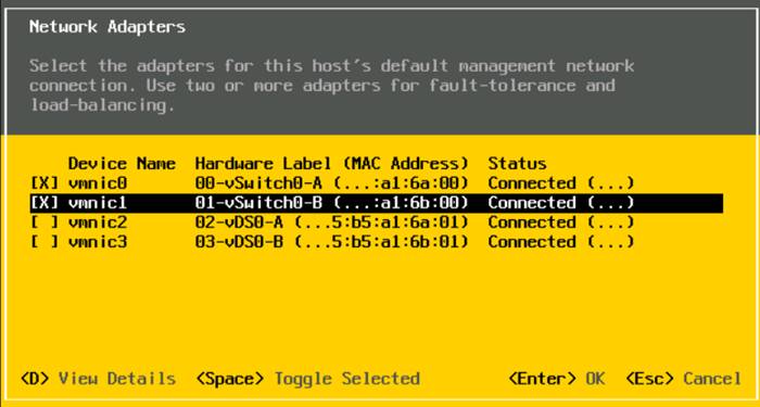
![]() In lab testing, examples have been seen where the vmnic and device ordering do not match. If this is the case, use the Consistent Device Naming (CDN) to note which vmnics are mapped to which vNICs and adjust the upcoming procedure accordingly.
In lab testing, examples have been seen where the vmnic and device ordering do not match. If this is the case, use the Consistent Device Naming (CDN) to note which vmnics are mapped to which vNICs and adjust the upcoming procedure accordingly.
11. Press Enter.
![]() Set the IB-MGMT VLAN as the native VLAN on the vSwitch0-A and vSwitch0-B vNICs which allows untagged VLAN packets from this interface to go into the IB-MGMT VLAN. Because of this, do not set a VLAN on this interface.
Set the IB-MGMT VLAN as the native VLAN on the vSwitch0-A and vSwitch0-B vNICs which allows untagged VLAN packets from this interface to go into the IB-MGMT VLAN. Because of this, do not set a VLAN on this interface.
12. Choose IPv4 Configuration and press Enter.
![]() If you are using DHCP to set the ESXi host networking configuration, alter this process as needed.
If you are using DHCP to set the ESXi host networking configuration, alter this process as needed.
13. Choose the “Set static IPv4 address and network configuration” option by using the arrow keys and space bar.
14. Move to the IPv4 Address field and enter the IP address for managing the ESXi host.
15. Move to the Subnet Mask field and enter the subnet mask for the ESXi host.
16. Move to the Default Gateway field and enter the default gateway for the ESXi host.
17. Press Enter to accept the changes to the IP configuration.
18. Choose the IPv6 Configuration option and press Enter.
19. Using the spacebar, choose Disable IPv6 (restart required) and press Enter.
20. Choose the DNS Configuration option and press Enter.
![]() Since the IP address is assigned manually, the DNS information must also be entered manually.
Since the IP address is assigned manually, the DNS information must also be entered manually.
21. Using the spacebar, choose “Use the following DNS server addresses and hostname:”
22. Move to the Primary DNS Server field and enter the IP address of the primary DNS server.
23. Optional: Move to the Alternate DNS Server field and enter the IP address of the secondary DNS server.
24. Move to the Hostname field and enter the fully qualified domain name (FQDN) for the ESXi host.
25. Press Enter to accept the changes to the DNS configuration.
26. Press Esc to exit the Configure Management Network submenu.
27. Press Y to confirm the changes and reboot the ESXi host.
Reset VMware ESXi Host VMkernel Port vmk0 MAC Address (Optional)
ESXi Host VM-Host-Infra-01, VM-Host-Infra-02, and VM-Host-Infra-03
By default, the MAC address of the management VMkernel port vmk0 is the same as the MAC address of the Ethernet port it is placed on. If the ESXi host’s boot LUN is remapped to a different server with different MAC addresses, a MAC address conflict will exist because vmk0 will retain the assigned MAC address unless the ESXi System Configuration is reset. To reset the MAC address of vmk0 to a random VMware-assigned MAC address, follow these steps:
1. From the ESXi console menu main screen, type Ctrl-Alt-F1 to access the VMware console command line interface. In the UCSM KVM, Ctrl-Alt-F1 appears in the list of Static Macros.
2. Log in as root.
3. Type esxcfg-vmknic –l to get a detailed listing of interface vmk0. vmk0 should be a part of the “Management Network” port group. Note the IP address and netmask of vmk0.
4. To remove vmk0, type esxcfg-vmknic –d “Management Network”.
5. To re-add vmk0 with a random MAC address, type esxcfg-vmknic –a –i <vmk0-ip> -n <vmk0-netmask> “Management Network”.
6. Verify vmk0 has been re-added with a random MAC address by typing esxcfg-vmknic –l.
7. Tag vmk0 as the management interface by typing esxcli network ip interface tag add -i vmk0 -t Management.
8. When vmk0 was re-added, if a message popped up saying vmk1 was marked as the management interface, type esxcli network ip interface tag remove -i vmk1 -t Management.
9. If this VMware ESXi host is iSCSI booted, the vmk1, iScsiBootPG-A interface’s MAC address can also be reset to a random, VMware-assigned MAC address.
a. Type esxcfg-vmknic –l to get a detailed listing of interface vmk1. vmk1 should be a part of the “iScsiBootPG-A” port group and should have a MAC address from the UCS MAC Pool. Note the IP address and netmask of vmk1.
10. To remove vmk1, type esxcfg-vmknic –d “iScsiBootPG-A.”
11. To re-add vmk1 with a random MAC address, type esxcfg-vmknic –a –i <vmk1-ip> -n <vmk1-netmask> -m 9000 “iScsiBootPG-A.”
12. Verify vmk1 has been re-added with a random MAC address by typing esxcfg-vmknic –l.
13. Type exit to log out of the command line interface.
14. Type Ctrl-Alt-F2 to return to the ESXi console menu interface.
FlexPod VMware ESXi Ansible Configuration
The following procedure can be used to configure the three VMware ESXi hosts from the management workstation.
1. Edit the following variable files to ensure proper Nexus variables are entered:
● FlexPod-M6/FlexPod-UCSM-M6/inventory
● FlexPod-M6/FlexPod-UCSM-M6/group_vars/all.yml
● FlexPod-M6/FlexPod-UCSM-M6/roles/ESXIhosts/defaults/main.yml
● FlexPod-M6/FlexPod-UCSM-M6/roles/ESXIiscsi/defaults/main.yml (If using iSCSI boot)
2. From /root/ FlexPod-M6/FlexPod-UCSM-M6, run the Setup_ESXi.yml Ansible playbook:
ansible-playbook ./Setup_ESXi.yml -i inventory
FlexPod VMware ESXi Manual Configuration
Although the VMware ESXi Ansible configuration configures all three ESXi hosts, the manual configuration, after the installation of necessary drivers, configures only the first host using the ESXi web interface then adds the second and third hosts after vCenter is installed.
Install VMware and Cisco VIC Drivers for the ESXi Host
Download the offline bundle for the Cisco VIC nfnic driver, Cisco UCS Tools Component and the NetApp NFS Plug-in for VMware VAAI to the Management workstation: https://customerconnect.vmware.com/downloads/details?downloadGroup=DT-ESXI70-CISCO-NFNIC-50015&productId=974 (Cisco-nfnic_5.0.0.15-1OEM.700.1.0.15843807_18697950.zip)
Cisco UCS Tools Component for ESXi 7.0 1.2.1 (ucs-tool-esxi_1.2.1-1OEM.zip)
NetApp NFS Plug-in for VMware VAAI 2.0 (NetAppNasPluginV2.0.zip)
![]() This document is using the driver versions shown above along with Cisco VIC nenic version 1.0.35.0 (already included in the Cisco Custom ISO) along with VMware vSphere version 7.0.2, Cisco UCS version 4.2(1i), and the latest patch of NetApp ONTAP 9.9.1. These were the versions validated and supported at the time this document was published. This document can be used as a guide for configuring future versions of software. Consult the Cisco UCS Hardware Compatibility List and the NetApp Interoperability Matrix Tool to determine supported combinations of firmware and software.
This document is using the driver versions shown above along with Cisco VIC nenic version 1.0.35.0 (already included in the Cisco Custom ISO) along with VMware vSphere version 7.0.2, Cisco UCS version 4.2(1i), and the latest patch of NetApp ONTAP 9.9.1. These were the versions validated and supported at the time this document was published. This document can be used as a guide for configuring future versions of software. Consult the Cisco UCS Hardware Compatibility List and the NetApp Interoperability Matrix Tool to determine supported combinations of firmware and software.
ESXi Hosts VM-Host-Infra-01, VM-Host-Infra-02, and VM-Host-Infra-03
To install VMware VIC Drivers, the UCS Tool, and the NetApp NFS Plug-in for VMware VAAI on the ESXi host VM-Host-Infra-01 and VM-Host-Infra-02, follow these steps:
1. Using an SCP program such as WinSCP, copy the three offline bundles referenced above to the /tmp directory on each ESXi host.
2. Using a ssh tool such as PuTTY, ssh to each VMware ESXi host. Log in as root with the root password.
3. Type cd /tmp.
4. Run the following commands on each host:
esxcli software component apply -d /tmp/Cisco-nfnic_5.0.0.15-1OEM.700.1.0.15843807_1869750.zip
esxcli software component apply -d /tmp/ucs-tool-esxi_1.2.1-1OEM.zip
esxcli software vib install -d /tmp/NetAppNasPluginV2.0.zip
reboot
5. After reboot, log back into each host and run the following commands and ensure the correct version is installed:
esxcli software vib list | grep nenic
esxcli software component list | grep nfnic
esxcli software component list | grep ucs
esxcli software vib list | grep NetApp
Log into the First VMware ESXi Host by Using VMware Host Client
ESXi Host VM-Host-Infra-01
To log into the VM-Host-Infra-01 ESXi host by using the VMware Host Client, follow these steps:
1. Open a web browser on the management workstation and navigate to the VM-Host-Infra-01 management IP address.
2. Enter root for the User name.
3. Enter the root password.
4. Click Login to connect.
5. Decide whether to join the VMware Customer Experience Improvement Program and click OK.
Set Up VMkernel Ports and Virtual Switch
ESXi Host VM-Host-Infra-01
To set up the VMkernel ports and the virtual switches on the first ESXi host, follow these steps:
![]() In this procedure, you’re only setting up the first ESXi host. The second and third hosts will be added to vCenter and setup from the vCenter HTML5 Interface.
In this procedure, you’re only setting up the first ESXi host. The second and third hosts will be added to vCenter and setup from the vCenter HTML5 Interface.
1. From the Host Client Navigator, choose Networking.
2. In the center pane, choose the Virtual switches tab.
3. Highlight the vSwitch0 line.
4. Choose Edit settings.
5. Change the MTU to 9000.
6. Expand NIC teaming.
7. In the Failover order section, choose vmnic1 and click Mark active.
8. Verify that vmnic1 now has a status of Active.
9. Click Save.
10. Choose Networking, then choose the Port groups tab.
11. In the center pane, right-click VM Network and choose Edit settings.
12. Name the port group IB-MGMT Network. Leave the VLAN ID set at 0.
13. Click Save to finalize the edits for the IB-MGMT Network port group.
14. Click Add port group.
15. Name the port group OOB-MGMT Network and enter the <OOB-MGMT-vlan-id> for the VLAN ID.
16. Click Add to finalize the edits for the OOB-MGMT port group.
17. At the top, choose the VMkernel NICs tab.
18. Click Add VMkernel NIC.
19. For New port group, enter VMkernel-Infra-NFS.
20. For Virtual switch, choose vSwitch0.
21. Enter <infra-nfs-vlan-id> for the VLAN ID.
22. Change the MTU to 9000.
23. Choose Static IPv4 settings and expand IPv4 settings.
24. Enter the ESXi host Infrastructure NFS IP address and netmask.
25. Leave TCP/IP stack set at Default TCP/IP stack and do not choose any of the Services.
26. Click Create.
27. Choose the Virtual Switches tab, then vSwitch0. The properties for vSwitch0 VMkernel NICs should be similar to the following example:
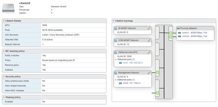
28. Choose Networking and the VMkernel NICs tab to confirm configured virtual adapters. The adapters listed should be similar to the following example:
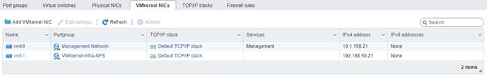
ESXi Host VM-Host-Infra-01
To mount the required datastores, follow these steps on the first ESXi host:
1. From the Host Client, choose Storage.
2. In the center pane, choose the Datastores tab.
3. In the center pane, choose New Datastore to add a new datastore.
4. In the New datastore popup, choose Mount NFS datastore and click Next.
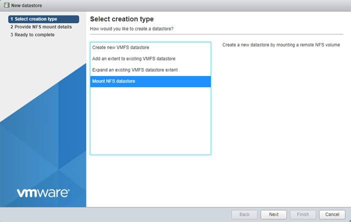
5. Input infra_datastore_01 for the datastore name. Input the IP address for the nfs-lif-01 LIF for the NFS server. Input /infra_datastore_01 for the NFS share. Set the NFS version to NFS 4. Click Next.
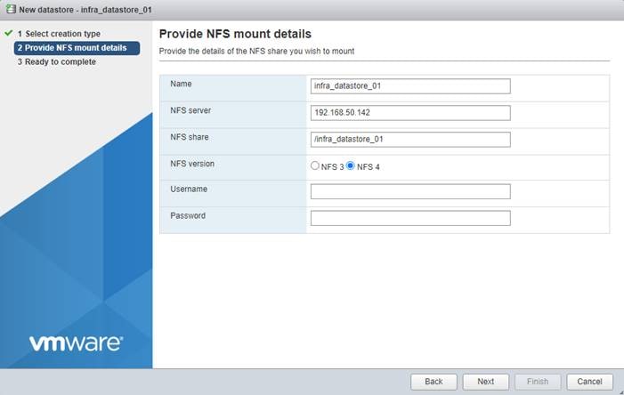
6. Click Finish. The datastore should now appear in the datastore list.
7. In the center pane, choose New Datastore to add a new datastore.
8. In the New datastore popup, choose Mount NFS datastore and click Next.
9. Input infra_datastore_02 for the datastore name. Input the IP address for the nfs-lif-02 LIF for the NFS server. Input /infra_datastore_02 for the NFS share. Set the NFS version to NFS 4. Click Next.
10. Click Finish. The datastore should now appear in the datastore list.
11. In the center pane, choose New Datastore to add a new datastore.
12. In the New datastore popup, choose Mount NFS datastore and click Next.
13. Input infra_swap for the datastore name. Input the IP address for the nfs-lif-01 LIF for the NFS server. Input /infra_swap for the NFS share. Set the NFS version to NFS 4. Click Next.
14. Click Finish. The datastore should now appear in the datastore list.
Configure NTP on First ESXi Host
ESXi Host VM-Host-Infra-01
To configure Network Time Protocol (NTP) on the first ESXi host, follow these steps:
1. From the Host Client, choose Manage.
2. In the center pane, choose System > Time & date.
3. Click Edit NTP settings.
4. Make sure “Manually configure the date and time on this host and enter the approximate date and time.
5. Select Use Network Time Protocol (enable NTP client).
6. Use the drop-down list to choose Start and stop with host.
7. Enter the two Nexus switch NTP addresses in the NTP servers box separated by a comma.
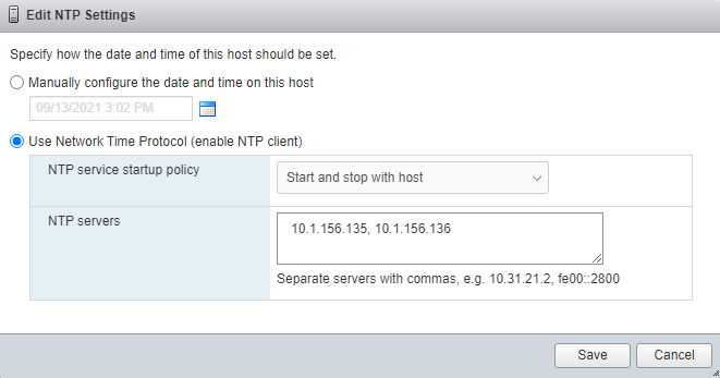
8. Click Save to save the configuration changes.
9. Select the Services tab.
10. Right-click ntpd and choose Start.
11. System > Time & date should now show Running for the NTP service status.
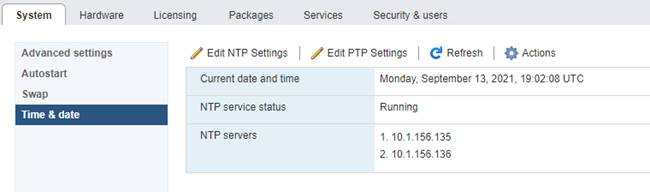
ESXi Host VM-Host-Infra-01
To configure host swap on the first ESXi host, follow these steps on the host:
1. From the Host Client, choose Manage.
2. In the center pane, choose System > Swap.
3. Click Edit settings.
4. Use the drop-down list to choose infra_swap. Leave all other settings unchanged.
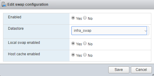
5. Click Save to save the configuration changes.
ESXi Host VM-Host-Infra-01
To configure the host power policy on the first ESXi host, follow these steps on the host:
![]() Implementation of this policy is recommended in https://www.cisco.com/c/en/us/products/collateral/servers-unified-computing/ucs-b-series-blade-servers/performance-tuning-guide-ucs-m6-servers.html for maximum VMware ESXi performance. If your organization has specific power policies, please set this policy accordingly.
Implementation of this policy is recommended in https://www.cisco.com/c/en/us/products/collateral/servers-unified-computing/ucs-b-series-blade-servers/performance-tuning-guide-ucs-m6-servers.html for maximum VMware ESXi performance. If your organization has specific power policies, please set this policy accordingly.
1. From the Host Client, choose Manage.
2. In the center pane, choose Hardware > Power Management.
3. Choose Change policy.
4. Choose High performance and click OK.
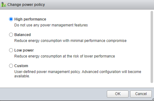
5. If you are implementing iSCSI boot, execute the VMware ESXi setup scripts in the FlexPod iSCSI Addition section.
VMware vCenter 7.0U2B
The procedures in the following subsections provide detailed instructions for installing the VMware vCenter 7.0U2B Server Appliance in a FlexPod environment. After the procedures are completed, a VMware vCenter Server will be configured.
Build the VMware vCenter Server Appliance
The VCSA deployment consists of 2 stages: installation and configuration. To build the VMware vCenter virtual machine, follow these steps:
1. Locate and copy the VMware-VCSA-all-7.0.2-17958471.iso file to the desktop of the management workstation. This ISO is for the VMware vSphere 7.0 U2 vCenter Server Appliance.
2. Using ISO mounting software, mount the ISO image as a disk on the management workstation. (For example, with the Mount command in Windows Server 2012 and above).
3. In the mounted disk directory, navigate to the vcsa-ui-installer > win32 directory and double-click installer.exe. The vCenter Server Appliance Installer wizard appears.
4. Click Install to start the vCenter Server Appliance deployment wizard.
5. Click NEXT in the Introduction section.
6. Read and accept the license agreement and click NEXT.
7. In the “vCenter Server deployment target” window, enter the FQDN or IP address of the first ESXi host, User name (root) and Password. Click NEXT.
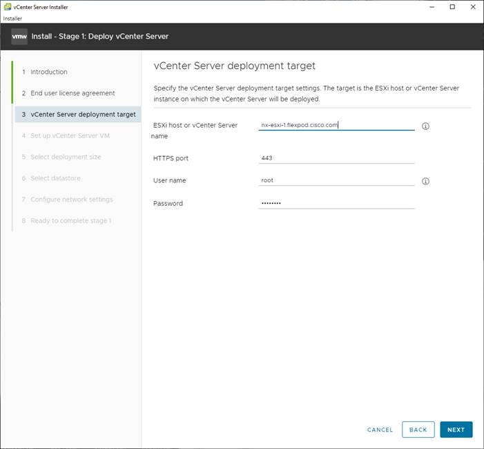
8. Click YES to accept the certificate.
9. Enter the Appliance VM name and password details shown in the “Set up vCenter Server VM” section. Click NEXT.
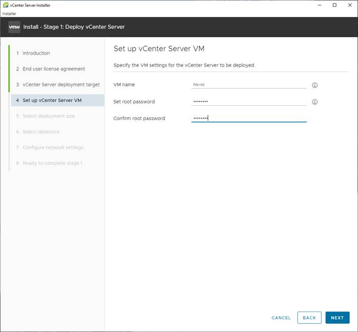
10. In the “Select deployment size” section, choose the Deployment size and Storage size. For example, choose “Small” and “Default.” Click NEXT.
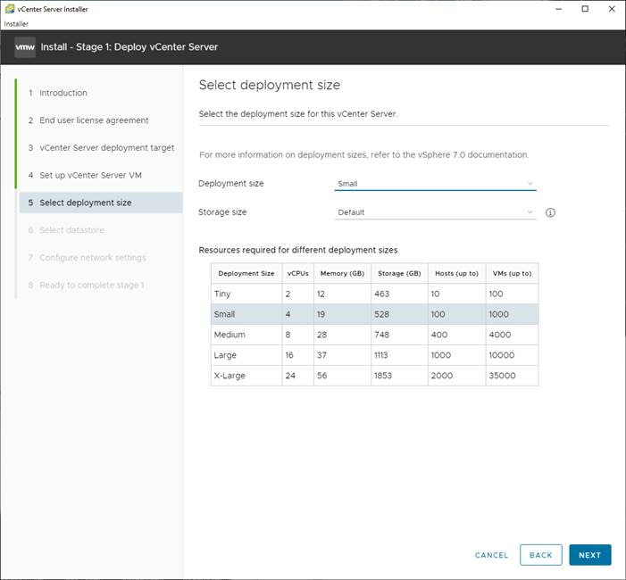
11. Choose infra_datastore_02 for storage. Click NEXT.
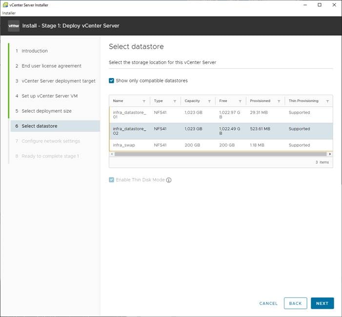
12. In the “Network Settings” section, configure the following settings:
a. Choose a Network: IB-MGMT Network
![]() It is important that the vCenter VM stay on the IB-MGMT Network on vSwitch0 and that it not get moved to a vDS. If vCenter is moved to a vDS and the virtual environment is completely shut down and then brought back up, and it is attempted to bring up vCenter on a different host than the one it was running on before the shutdown, vCenter will not have a functional network connection. With the vDS, for a virtual machine to move from one host to another, vCenter must be up and running to coordinate the move of the virtual ports on the vDS. If vCenter is down, the port move on the vDS cannot occur correctly. Moving vCenter to a different host on vSwitch0 to be brought up always occurs correctly without requiring vCenter to already be up and running.
It is important that the vCenter VM stay on the IB-MGMT Network on vSwitch0 and that it not get moved to a vDS. If vCenter is moved to a vDS and the virtual environment is completely shut down and then brought back up, and it is attempted to bring up vCenter on a different host than the one it was running on before the shutdown, vCenter will not have a functional network connection. With the vDS, for a virtual machine to move from one host to another, vCenter must be up and running to coordinate the move of the virtual ports on the vDS. If vCenter is down, the port move on the vDS cannot occur correctly. Moving vCenter to a different host on vSwitch0 to be brought up always occurs correctly without requiring vCenter to already be up and running.
b. IP version: IPV4
c. IP assignment: static
d. FQDN: <vcenter-fqdn>
e. IP address: <vcenter-ip>
f. Subnet mask or prefix length: <vcenter-subnet-mask>
g. Default gateway: <vcenter-gateway>
h. DNS Servers: <dns-server1>,<dns-server2>
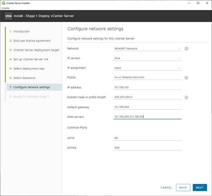
13. Click NEXT.
14. Review all values and click FINISH to complete the installation.
![]() The vCenter Server appliance installation will take a few minutes to complete.
The vCenter Server appliance installation will take a few minutes to complete.
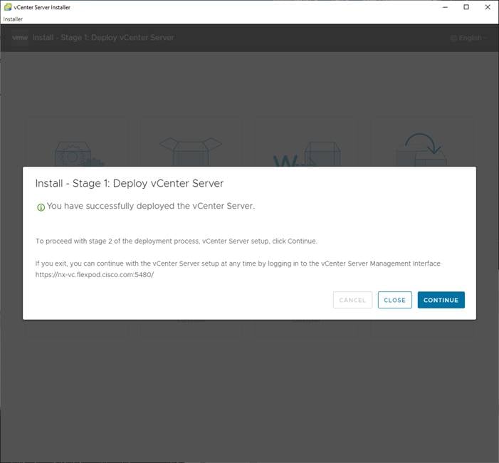
15. Click CONTINUE to proceed with stage 2 configuration.
16. Click NEXT.
17. In the vCenter Server configuration window, configure these settings:
a. Time Synchronization Mode: Synchronize time with NTP servers
b. NTP Servers: <nexus-a-ntp-ip>,<nexus-b-ntp-ip>
c. SSH access: Enabled
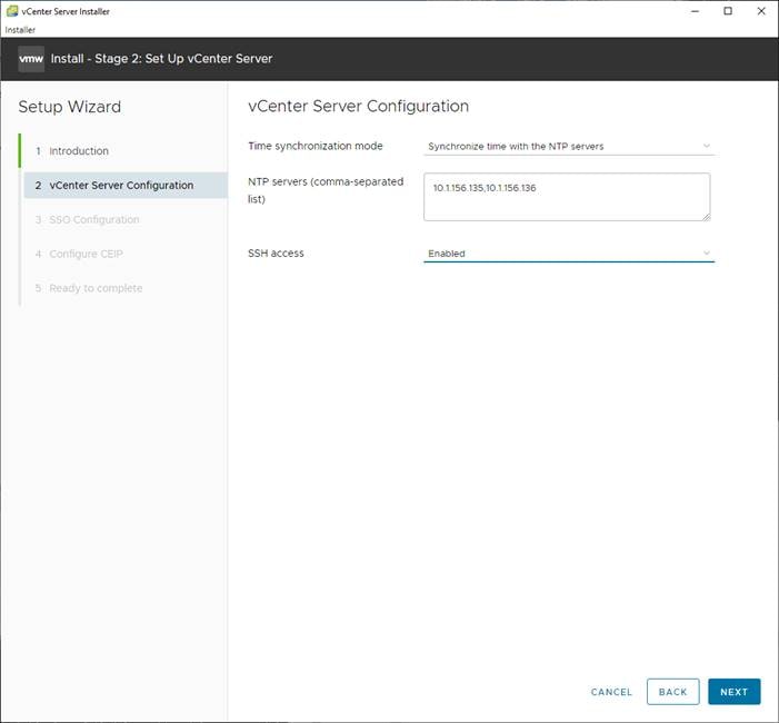
18. Click NEXT.
19. Complete the SSO configuration as shown below (or according to your organization’s security policies):
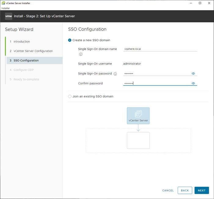
20. Click NEXT.
21. Decide whether to join VMware’s Customer Experience Improvement Program (CEIP).
22. Click NEXT.
23. Review the configuration and click FINISH.
24. Click OK.
![]() vCenter Server setup will take a few minutes to complete.
vCenter Server setup will take a few minutes to complete.
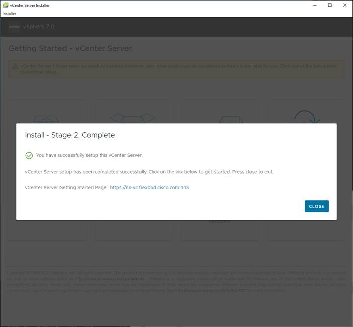
25. Click CLOSE. Eject or unmount the VCSA installer ISO.
If a vCenter deployment size of Small or larger was selected in the vCenter setup, it is possible that the VCSA’s CPU setup does not match the Cisco UCS server CPU hardware configuration. Cisco UCS B and C-Series servers are normally 2-socket servers. In this validation, the Small deployment size was selected and vCenter was setup for a 4-socket server. This setup can cause issues in the VMware ESXi cluster Admission Control. To resolve the Admission Control issue, follow these steps:
1. Open a web browser on the management workstation and navigate to https://<VM-Host-Infra-01-IP>.
2. Enter root for the user name.
3. Enter the root password.
4. Click Login to connect.
5. Choose Virtual Machines.
6. In the center pane, right-click the vCenter VM and choose Edit settings.
7. In the Edit settings window, expand CPU and check the value of Sockets.
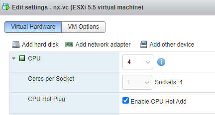
8. If the number of Sockets does not match your server configuration, it will need to be adjusted. Click Cancel.
9. If the number of Sockets needs to be adjusted:
a. Right-click the vCenter VM and choose Guest OS > Shut down. Click Yes on the confirmation.
10. Once vCenter is shut down, right-click the vCenter VM and choose Edit settings.
11. In the Edit settings window, expand CPU and change the Cores per Socket value to make the Sockets value equal to your server configuration (normally 2).
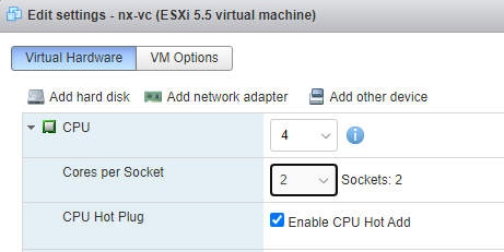
12. Click Save.
13. Right-click the vCenter VM and choose Power > Power on. Wait approximately 10 minutes for vCenter to come up.
Install VMware vCenter Server Log4j Workaround
To install the VMware vCenter Server log4j workaround, follow the steps: https://kb.vmware.com/s/article/87081.
Setup VMware vCenter Server
To setup the VMware vCenter Server, follow these steps:
1. Using a web browser, navigate to https://<vcenter-ip-address>:5480. You will need to navigate security screens.
2. Log into the VMware vCenter Server Management interface as root with the root password set in the vCenter installation.
3. In the menu on the left, choose Time.
4. Choose EDIT to the right of Time zone.
5. Choose the appropriate Time zone and click SAVE.
6. In the menu on the left choose Administration.
7. According to your Security Policy, adjust the settings for the root user and password.
8. In the menu on the left choose Update.
9. Follow the prompts to STAGE AND INSTALL any available vCenter updates. In this validation, vCenter version 7.0.2.00200 was installed.
10. In the upper right-hand corner of the screen, choose root > Logout to logout of the Appliance Management interface.
11. Using a web browser, navigate to https://<vcenter-fqdn>. You will need to navigate security screens.
![]() With VMware vCenter 7.0 and above, the use of the vCenter FQDN is required.
With VMware vCenter 7.0 and above, the use of the vCenter FQDN is required.
12. Choose LAUNCH VSPHERE CLIENT (HTML5).
![]() Although the previous versions of this document used the FLEX vSphere Web Client, the VMware vSphere HTML5 Client is the only option in vSphere 7 and will be used going forward.
Although the previous versions of this document used the FLEX vSphere Web Client, the VMware vSphere HTML5 Client is the only option in vSphere 7 and will be used going forward.
13. Log in using the Single Sign-On username (administrator@vsphere.local) and password created during the vCenter installation. Dismiss the Licensing warning at this time.
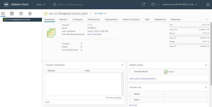
Add AD User Authentication to vCenter (Optional)
If an AD Infrastructure is set up in this FlexPod environment, you can setup in AD and authenticate from vCenter.
To add an AD user authentication to the vCenter, follow these steps:
1. In the AD Infrastructure, using the Active Directory Users and Computers tool, setup a Domain Administrator user with a user name such as flexadmin (FlexPod Admin).
2. Connect to https://<vcenter-ip> and choose LAUNCH VSPHERE CLIENT (HTML5).
3. Log in as Administrator@vsphere.local (or the SSO user set up in vCenter installation) with the corresponding password.
4. Under Menu, choose Administration. In the list on the left, under Single Sign On, choose Configuration.
5. In the center pane, under Configuration, choose the Identity Provider tab.
6. In the list under Type, select Active Directory Domain.
7. Choose JOIN AD.
8. Fill in the AD domain name, the Administrator user, and the domain Administrator password. Do not fill in an Organizational unit. Click JOIN.
9. Click Acknowledge.
10. In the list on the left under Deployment, choose System Configuration. Choose the radio button to choose the vCenter, then choose REBOOT NODE.
11. Input a reboot reason and click REBOOT. The reboot will take approximately 10 minutes for full vCenter initialization.
12. Log back into the vCenter vSphere HTML5 Client as Administrator@vsphere.local.
13. Under Menu, choose Administration. In the list on the left, under Single Sign On, choose Configuration.
14. In the center pane, under Configuration, choose the Identity Provider tab. Under Type, select Identity Sources. Click ADD.
15. Make sure Active Directory (Integrated Windows Authentication) is selected, your Windows Domain name is listed, and Use machine account is selected. Click ADD.
16. In the list select the Active Directory (Integrated Windows Authentication) Identity source type. If desired, select SET AS DEFAULT and click OK.
17. On the left under Access Control, choose Global Permissions.
18. In the center pane, click the + sign to add a Global Permission.
19. In the Add Permission window, choose your AD domain for the Domain.
20. On the User/Group line, enter either the FlexPod Admin username or the Domain Admins group. Leave the Role set to Administrator. Check the box for Propagate to children.
![]() The FlexPod Admin user was created in the Domain Admins group. The selection here depends on whether the FlexPod Admin user will be the only user used in this FlexPod or you would like to add other users later. By selecting the Domain Admins group, any user placed in that group in the AD domain will be able to login to vCenter as an Administrator.
The FlexPod Admin user was created in the Domain Admins group. The selection here depends on whether the FlexPod Admin user will be the only user used in this FlexPod or you would like to add other users later. By selecting the Domain Admins group, any user placed in that group in the AD domain will be able to login to vCenter as an Administrator.
21. Click OK to add the selected User or Group. The user or group should now appear in the Global Permissions list with the Administrator role.
22. Log out and log back into the vCenter HTML5 Client as the FlexPod Admin user. You will need to add the domain name to the user, for example, flexadmin@domain.
vCenter and ESXi Ansible Setup
To complete the configuration of the VMware vCenter and the three management ESXi hosts:
1. Edit the following variable files to ensure proper Nexus variables are entered:
● FlexPod-M6/FlexPod-UCSM-M6/inventory
● FlexPod-M6/FlexPod-UCSM-M6/group_vars/all.yml
● FlexPod-M6/FlexPod-UCSM-M6/roles/ESXIpostvC/defaults/main.yml
2. From /root/ FlexPod-M6/FlexPod-UCSM-M6, run the Setup_vCenter.yml Ansible playbook:
ansible-playbook ./Setup_vCenter.yml -i inventory
To manually set up vCenter, follow these steps:
Initial vCenter Setup
1. In the center pane, choose ACTIONS > New Datacenter.
2. Type “FlexPod-DC” in the Datacenter name field.
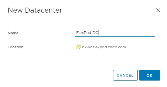
3. Click OK.
4. Expand the vCenter.
5. Right-click the datacenter FlexPod-DC in the list in the left pane. Choose New Cluster.
6. Name the cluster FlexPod-Management.
7. Turn on DRS and vSphere HA. Do not turn on vSAN.
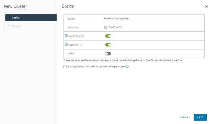
8. Click NEXT and then click FINISH to create the new cluster.
9. Right-click “FlexPod-Management” and choose Settings.
10. Choose Configuration > General in the list located and choose EDIT.
11. Choose Datastore specified by host and click OK.
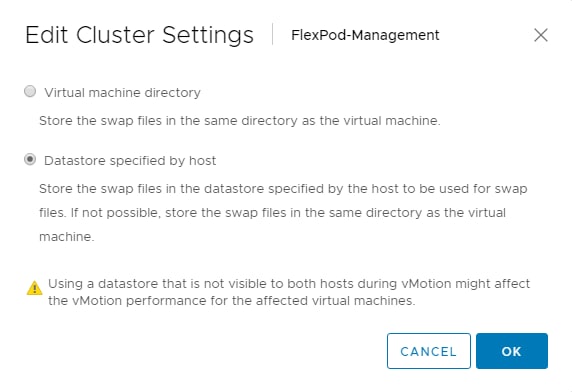
12. Right-click FlexPod-Management and click Add Hosts.
13. In the IP address or FQDN field, enter either the IP address or the FQDN of the first VMware ESXi host. Enter root as the Username and the root password. Click NEXT.
14. In the Security Alert window, choose the host and click OK.
15. Verify the Host summary information and click NEXT.
16. Ignore warnings about the host being moved to Maintenance Mode and click FINISH to complete adding the host to the cluster.
17. The added ESXi host will have Warnings that the ESXi Shell and SSH have been enabled. These warnings can be suppressed. The host will also have a TPM Encryption Key Recovery alert that can be reset to green.
18. In the list, right-click the added ESXi host and choose Settings.
19. In the center pane under Virtual Machines, choose Swap File location.
20. On the right, click EDIT.
21. Because of a known issue with the vCenter UI, you will need to use the TAB key to move the cursor to the first datastore in the datastore list. Then use the arrow keys to move the highlight to the infra_swap datastore. Once the infra_swap datastore is highlighted, use the spacebar to select it and click OK.
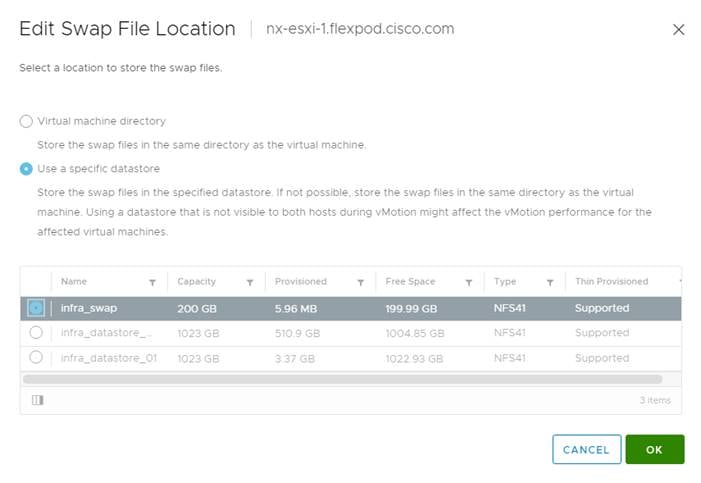
22. In the list under Storage, choose Storage Devices. Make sure the NETAPP Fibre Channel Disk LUN 0 or NETAPP iSCSI Disk LUN 0 is selected.
23. Choose the Paths tab.
24. Ensure that 4 paths appear, two of which should have the status Active (I/O).
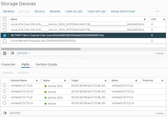
FlexPod VMware vSphere Distributed Switch (vDS)
This section provides detailed procedures for installing the VMware vDS in vCenter and on the first FlexPod ESXi Management Host.
In the Cisco UCS setup section of this document two sets of vNICs were setup. The vmnic ports associated with the vDS0-A and B vNICs will be placed on the VMware vDS in this procedure. The vMotion VMkernel port(s) will be placed on the vDS.
A vMotion, and a VM-Traffic port group will be added to the vDS. Any additional VLAN-based port groups added to the vDS would need to have the corresponding VLANs added to the Cisco UCS LAN cloud, to the Cisco UCS vDS0-A and B vNIC templates, and to the Cisco Nexus 9K switches and vPC peer-link interfaces on the switches.
In this document, the infrastructure ESXi management VMkernel ports, the In-Band management interfaces including the vCenter management interface, and the infrastructure NFS VMkernel ports are left on vSwitch0 to facilitate bringing the virtual environment back up in the event it needs to be completely shut down. The vMotion VMkernel ports are moved to the vDS to allow QoS marking of vMotion to be done at the VLAN level in the vDS if vMotion needs to have QoS policies applied in the future. The vMotion port group is also pinned to Cisco UCS fabric B. Pinning should be done in a vDS to ensure consistency across all ESXi hosts.
Configure the VMware vDS in vCenter
VMware vSphere Web Client
To configure the vDS, follow these steps:
1. After logging into the VMware vSphere HTML5 Client, choose Networking under Menu.
2. Right-click the FlexPod-DC datacenter and choose Distributed Switch > New Distributed Switch.
3. Give the Distributed Switch a descriptive name (vDS0) and click NEXT.
4. Make sure version 7.0.2 – ESXi 7.0.2 and later is selected and click NEXT.
5. Change the Number of uplinks to 2. If VMware Network I/O Control is to be used for Quality of Service, leave Network I/O Control Enabled. Otherwise, Disable Network I/O Control. Enter VM-Traffic for the Port group name. Click NEXT.
6. Review the information and click FINISH to complete creating the vDS.
7. Expand the FlexPod-DC datacenter and the newly created vDS. Choose the newly created vDS.
8. Right-click the VM-Traffic port group and choose Edit Settings.
9. Choose VLAN.
10. Choose VLAN for VLAN type and enter the VM-Traffic VLAN ID. Click OK.
11. Right-click the vDS and choose Settings > Edit Settings.
12. In the Edit Settings window, choose the Advanced tab.
13. Change the MTU to 9000. The Discovery Protocol can optionally be changed to Link Layer Discovery Protocol and the Operation to Both. Click OK.
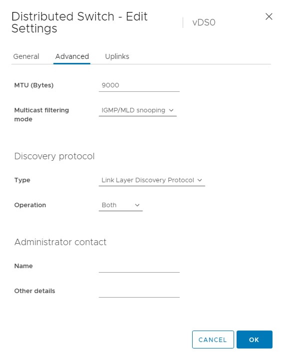
14. For the vMotion port group, right-click the vDS, choose Distributed Port Group > New Distributed Port Group.
15. Enter vMotion as the name and click NEXT.
16. Set the VLAN type to VLAN, enter the VLAN ID used for vMotion, check the box for Customize default policies configuration, and click NEXT.
17. Leave the Security options set to Reject and click NEXT.
18. Leave the Ingress and Egress traffic shaping options as Disabled and click NEXT.
19. Choose Uplink 1 from the list of Active uplinks and click MOVE DOWN twice to place Uplink 1 in the list of Standby uplinks. This will pin all vMotion traffic to UCS Fabric Interconnect B except when a failure occurs.
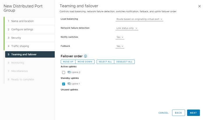
20. Click NEXT.
21. Leave NetFlow disabled and click NEXT.
22. Leave Block all ports set as No and click NEXT.
23. Confirm the options and click FINISH to create the port group.
24. Right-click the vDS and choose Add and Manage Hosts.
25. Make sure Add hosts is selected and click NEXT.
26. Click the green + sign to add New hosts. Choose the one configured FlexPod Management host and click OK. Click NEXT.
27. Choose vmnic2 and click Assign uplink. Choose Uplink 1 and click OK. Choose vmnic3 and click Assign uplink. Choose Uplink 2 and click OK.
![]() It is important to assign the uplinks as shown below. This allows the port groups to be pinned to the appropriate Cisco UCS fabric.
It is important to assign the uplinks as shown below. This allows the port groups to be pinned to the appropriate Cisco UCS fabric.
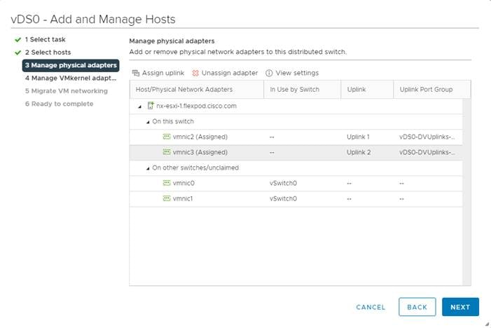
28. Click NEXT.
29. Do not migrate any VMkernel ports and click NEXT.
30. Do not migrate any virtual machine networking ports. Click NEXT.
31. Click FINISH to complete adding the ESXi host to the vDS.
32. Select Hosts and Clusters under Menu and select the first ESXi host. In the center pane, select the Configure tab.
33. In the list under Networking, select VMkernel adapters.
34. Select ADD NETWORKING.
35. In the Add Networking window, ensure that VMkernel Network Adapter is selected and click NEXT.
36. Ensure that Select and existing network is selected and click BROWSE .
37. Select vMotion and click OK.
38. Click NEXT.
39. From the MTU drop-down list, select Custom and ensure the MTU is set to 9000.
40. From the TCP/IP stack drop-down list, select vMotion. Click NEXT.
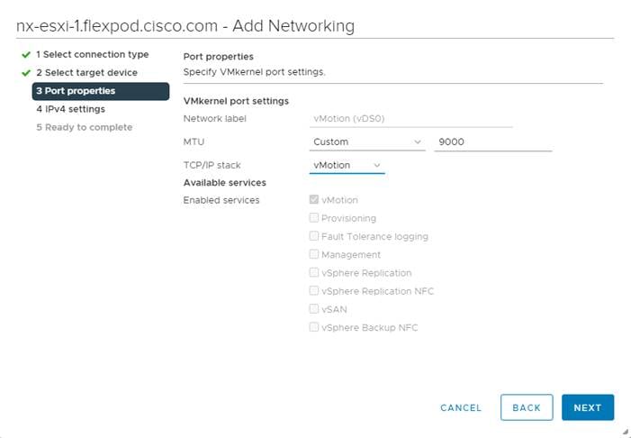
41. Select Use static IPv4 settings and fill in the IPv4 address and Subnet mask for the first ESXi host’s vMotion IP address. Click NEXT.
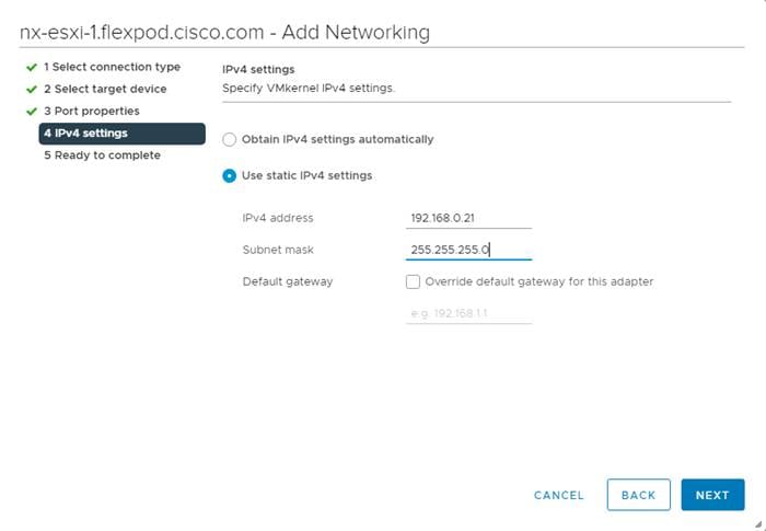
42. Review the information and click FINISH to complete adding the vMotion VMkernel port.
Add and Configure VMware ESXi Hosts in vCenter
This section details the steps to add and configure an ESXi host in vCenter. This section assumes the host has had the VMware ESXi 7.0 U2 Cisco Custom ISO installed, the management IP address set, the nfnic driver updated, and the Cisco UCS Tool and NetApp NFS Plug-in for VMware VAAI installed. This procedure is initially being run on the second and third ESXi management hosts but can be run on any added ESXi host.
ESXi Host VM-Host-Infra-02 and VM-Host-Infra-03
To add the ESXi host(s) to vCenter, follow these steps:
1. From the Home screen in the VMware vCenter HTML5 Interface, choose Menu > Hosts and Clusters.
2. Right-click the “FlexPod-Management” cluster and click Add Hosts.
3. In the IP address or FQDN field, enter either the IP address or the FQDN name of the configured VMware ESXi host. Also enter the user id (root) and associated password. If more than one host is being added, add the corresponding host information, optionally selecting “Use the same credentials for all hosts.” Click NEXT.
4. Choose all hosts being added and click OK to accept the thumbprint(s).
5. Review the host details and click NEXT to continue.
6. Review the configuration parameters and click FINISH to add the host(s).
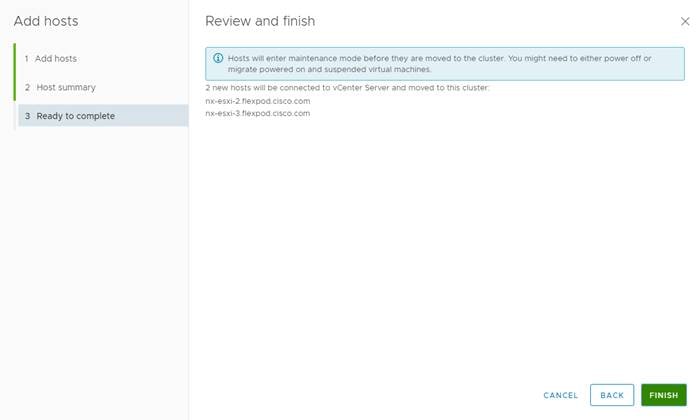
![]() The added ESXi host(s) will be placed in Maintenance Mode and will have Warnings that the ESXi Shell and SSH have been enabled. These warnings can be suppressed. The TPM Encryption Recovery Key Backup Alarm can also be Reset to Green.
The added ESXi host(s) will be placed in Maintenance Mode and will have Warnings that the ESXi Shell and SSH have been enabled. These warnings can be suppressed. The TPM Encryption Recovery Key Backup Alarm can also be Reset to Green.
Set Up VMkernel Ports and Virtual Switch
ESXi Host VM-Host-Infra-02 and VM-Host-Infra-03
To set up the VMkernel ports and the virtual switches on the ESXi host, follow these steps:
1. In the vCenter HTML5 Interface, under Hosts and Clusters choose the ESXi host.
2. In the center pane, choose the Configure tab.
3. In the list, choose Virtual switches under Networking.
4. Expand Standard Switch: vSwitch0.
5. Choose EDIT to Edit settings.
6. Change the MTU to 9000.
7. Choose Teaming and failover located on the left.
8. In the Failover order section, use the arrow icons to move the vmnics until both are Active adapters.
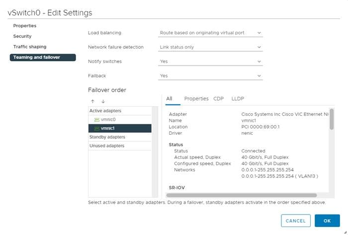
9. Click OK.
10. In the center pane, to the right of VM Network click … > Remove to remove the port group. Click YES on the confirmation.
11. Click ADD NETWORKING to add a new VM port group.
12. Choose Virtual Machine Port Group for a Standard Switch and click NEXT.
13. Ensure vSwitch0 is shown for Select an existing standard switch and click NEXT.
14. Name the port group “IB-MGMT Network” and leave the VLAN ID field set to None (0). Click NEXT.
![]() The IB-MGMT VLAN was set as the native VLAN for the vSwitch0 vNIC templates, allowing DHCP to be used on ESXi vmk0 without putting in a VLAN ID for this port. Since this port group is in the same VLAN, the port group’s VLAN ID should also be set to 0.
The IB-MGMT VLAN was set as the native VLAN for the vSwitch0 vNIC templates, allowing DHCP to be used on ESXi vmk0 without putting in a VLAN ID for this port. Since this port group is in the same VLAN, the port group’s VLAN ID should also be set to 0.
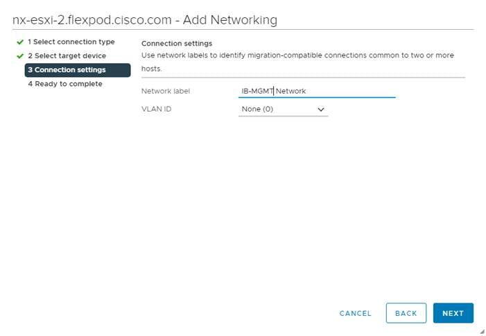
15. Click FINISH to complete adding the IB-MGMT Network VM port group.
16. Click ADD NETWORKING to add a new VM port group.
17. Choose Virtual Machine Port Group for a Standard Switch and click NEXT.
18. Ensure vSwitch0 is shown for Select an existing standard switch and click NEXT.
19. Name the port group “OOB-MGMT Network” and input <OOB-MGMT-vlan-id> for the VLAN ID field. Click NEXT.
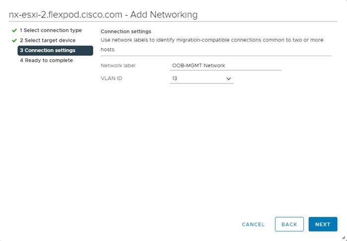
20. Click FINISH to complete adding the OOB-MGMT Network VM port group.
21. Located on the left under Networking, choose VMkernel adapters.
22. In the center pane, click Add Networking.
23. Make sure VMkernel Network Adapter is selected and click NEXT.
24. Choose Select an existing standard switch and click BROWSE. Choose vSwitch0 and click OK. Click NEXT.
25. For Network label, enter VMkernel-Infra-NFS.
26. Enter <infra-nfs-vlan-id> for the VLAN ID.
27. Choose Custom for MTU and make sure 9000 is entered.
28. Leave the Default TCP/IP stack selected and do not choose any of the Enabled services. Click NEXT.
29. Choose Use static IPv4 settings and enter the IPv4 address and subnet mask for the Infra-NFS VMkernel port for this ESXi host.
30. Click NEXT.
31. Review the settings and click FINISH to create the VMkernel port.
32. Under Networking, choose Virtual switches, then expand vSwitch0. The properties for vSwitch0 should be similar to the following example:
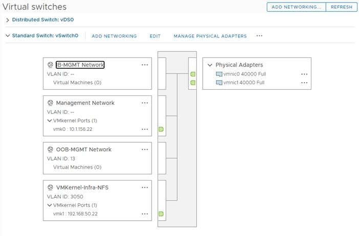
33. Repeat steps 1 - 32 for all hosts being added.
ESXi Host VM-Host-Infra-02 and VM-Host-Infra-03
To mount the required datastores, follow these steps on the ESXi host(s):
1. From the vCenter Home screen, choose Menu > Storage.
2. Expand FlexPod-DC.
3. Right-click infra_datastore_01 and choose Mount Datastore to Additional Hosts.
4. Choose the ESXi host(s) and click OK.
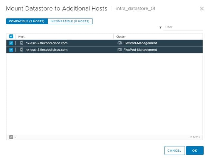
5. Repeat steps 1 - 4 to mount the infra_datastore_02 and infra_swap datastores to the ESXi host(s).
6. Choose infra_datastore_01. In the center pane, choose Hosts. Verify the ESXi host(s) now has the datastore mounted. Repeat this process to also verify that infra_datastore_02 and infra_swap are also mounted on all hosts.
ESXi Host VM-Host-Infra-02 and VM-Host-Infra-03
To configure Network Time Protocol (NTP) on the ESXi host(s), follow these steps:
1. In the vCenter HTML5 Interface, under Hosts and Clusters choose the ESXi host.
2. In the center pane, choose the Configure tab.
3. In the list under System, choose Time Configuration.
4. To the right of Manual Time Configuration, click EDIT.
5. Set the correct local time and click OK.
6. To the right of Network Time Protocol, click EDIT.
7. Check the box for Enable.
8. Enter the two Nexus switch NTP IP addresses in the NTP servers box separated by a comma.
9. Check the box for Start NTP Service.
10. Use the drop-down list to choose Start and stop with host.
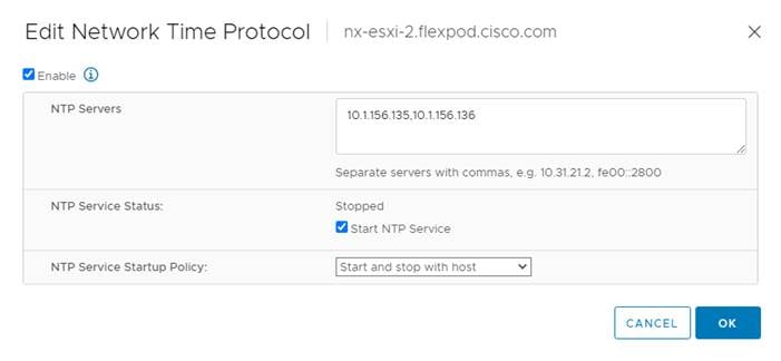
11. Click OK to save the configuration changes.
12. Verify that NTP service is now enabled and running, and the clock is now set to approximately the correct time.
Change ESXi Power Management Policy
ESXi Host VM-Host-Infra-02 and VM-Host-Infra-03
To change the ESXi power management policy, follow these steps:
![]() Implementation of this policy is recommended in Performance Tuning Guide for Cisco UCS M5 Servers for maximum VMware ESXi performance. If your organization has specific power policies, please set this policy accordingly.
Implementation of this policy is recommended in Performance Tuning Guide for Cisco UCS M5 Servers for maximum VMware ESXi performance. If your organization has specific power policies, please set this policy accordingly.
1. In the list under Hardware, choose Overview. Scroll to the bottom and to the right of Power Management, choose EDIT POWER POLICY.
2. Choose High performance and click OK.
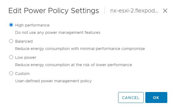
Add the ESXi Host(s) to the VMware Virtual Distributed Switch
ESXi Host VM-Host-Infra-02 and VM-Host-Infra-03
To add the ESXi host(s) to the VMware vDS, follow these steps on the host:
1. After logging into the VMware vSphere HTML5 Client, choose Networking under Menu.
2. Right-click the vDS (vDS0) and click Add and Manage Hosts.
3. Make sure Add hosts is selected and click NEXT.
4. Click the green + sign to add New hosts. Choose the configured FlexPod Management host(s) and click OK. Click NEXT.
5. Choose vmnic2 on each host and click Assign uplink. Choose Uplink 1 and click OK. Choose vmnic3 on each host and click Assign uplink. Choose Uplink 2 and click OK. If more than one host is being connected to the vDS, check the box for Apply this uplink assignment to the rest of the hosts.
![]() It is important to assign the uplinks as shown below. This allows the port groups to be pinned to the appropriate Cisco UCS fabric.
It is important to assign the uplinks as shown below. This allows the port groups to be pinned to the appropriate Cisco UCS fabric.
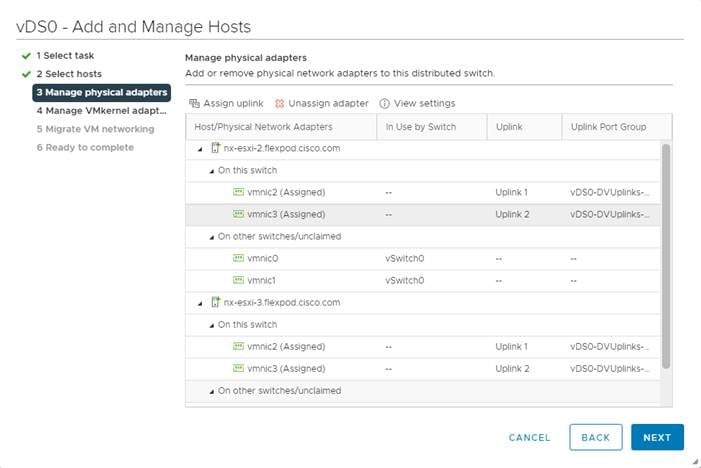
6. Click NEXT.
7. Do not migrate any VMkernel ports and click NEXT.
8. Do not migrate any VM ports and click NEXT.
9. Click FINISH to complete adding the ESXi host(s) to the vDS.
Add the vMotion VMkernel Port(s) to the ESXi Host
ESXi Host VM-Host-Infra-01, VM-Host-Infra-02 and VM-Host-Infra-03
To add the vMotion VMkernel Port to the ESXi host(s) on the VMware vDS, follow these steps on the host:
1. In the vCenter HTML5 Interface, under Hosts and Clusters choose the ESXi host.
2. Click the Configure tab.
3. In the list under Networking, choose VMkernel adapters.
4. Choose Add Networking to Add host networking.
5. Make sure VMkernel Network Adapter is selected and click NEXT.
6. Choose BROWSE to the right of Select an existing network.
7. Choose vMotion on the vDS and click OK.
8. Click NEXT.
9. Make sure the Network label is vMotion with the vDS in parenthesis. From the drop-down list, select Custom for MTU and make sure the MTU is set to 9000. Choose the vMotion TCP/IP stack and click NEXT.
10. Choose Use static IPv4 settings and input the host’s vMotion IPv4 address and Subnet mask.
11. Click NEXT.
12. Review the parameters and click FINISH to add the vMotion VMkernel port.
13. If NetApp VSC is installed, under Hosts and Clusters, right-click the host and click NetApp VSC > Set Recommended Values. Reboot the host.
14. If this is an iSCSI-booted host, execute the instructions in the Appendix for an iSCSI-booted host being added in vCenter.
15. Exit Maintenance Mode on each ESXi host in Maintenance Mode.
16. Migrate the vCenter VM to another ESXi host to move its swap into the infra_swap datastore.
Execute the following steps whether the Ansible or manual setup of VMware vCenter was done.
Configure ESXi Host Swap
ESXi Host VM-Host-Infra-01, VM-Host-Infra-02 and VM-Host-Infra-03
To configure host swap on the ESXi host(s), follow these steps on the host:
1. In the vCenter HTML5 Interface, under Hosts and Clusters choose the ESXi host.
2. In the center pane, choose the Configure tab.
3. In the list under System, choose System Swap.
4. Located on the right, click EDIT.
5. Choose Can use datastore and use the drop-down list to choose infra_swap. Leave all other settings unchanged.
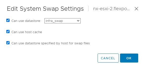
6. Click OK to save the configuration changes.
7. In the list under Virtual Machines, choose Swap File Location.
8. Located on the right, click EDIT.
9. Because of a known issue with the vCenter UI, you will need to use the TAB key to move the cursor to the first datastore in the datastore list. Then use the arrow keys to move the highlight to the infra_swap datastore. Once the infra_swap datastore is highlighted, use the spacebar to select it and click OK.

Configure ESXi IPMI/iLO Settings for Power Management (Optional)
ESXi Host VM-Host-Infra-01, VM-Host-Infra-02 and VM-Host-Infra-03
The vSphere Distributed Power Management (DPM) feature allows a DRS cluster to reduce its power consumption by powering hosts on and off based on cluster resource utilization. In order to implement this optional feature, an IPMI Access Profile was configured in Cisco UCS Manager and assigned to each service profile template. This procedure configures IPMI access for each ESXi host allowing DPM to be configured. To configure ESXi IPMI/iLO Settings for Power Management for each ESXi host, follow these steps:
1. In Cisco UCS Manager, select the ESXi host’s corresponding service profile template under Servers > Service Profiles > root > Sub-Organizations > FlexPod Organization.
2. On the right, click the link for the Associated Server in the format of “sys/chassis-1/blade-1”. A new window should pop up.
3. In the Properties for: window, select the Inventory tab. Then select the CIMC tab.
4. Under the Outband IPv4 tab, note the IP address and MAC.
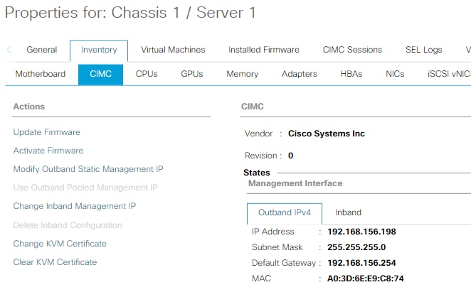
5. In the VMware vSphere Client, under Hosts and Clusters, select the ESXi host. In the center pane, select the Configure tab, and select Power Management under System.
6. Click EDIT.
7. Fill in the User name (ipmiadmin), the corresponding password, and the BMC IP address and BMC MAC address from Cisco UCS Manager.
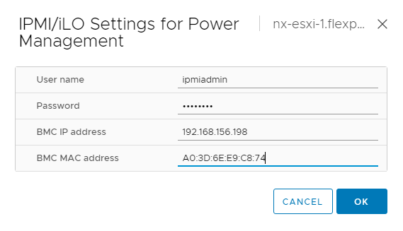
8. Click OK. The ESXi host will query the server CIMC at the BMC IP address and verify the BMC MAC address. If an error occurs, make sure the correct server information is being entered.
![]() The BMC MAC address is hard coded in the CIMC (not part of the service profile), and this set of parameters will need to be entered again if the service profile is associated to a different server.
The BMC MAC address is hard coded in the CIMC (not part of the service profile), and this set of parameters will need to be entered again if the service profile is associated to a different server.
9. Repeat this process for each VMware ESXi host.
Check ESXi Host Fibre Channel Pathing
ESXi Host VM-Host-Infra-01, VM-Host-Infra-02 and VM-Host-Infra-03
For fibre channel SAN-booted ESXi hosts, to ensure that the host(s) boot disk contains all required fibre channel paths, follow these steps:
1. In the list under Storage, choose Storage Devices. Make sure the NETAPP Fibre Channel Disk is selected.
2. Choose the Paths tab.
3. Ensure that 4 fibre channel paths appear, two of which should have the status Active (I/O).
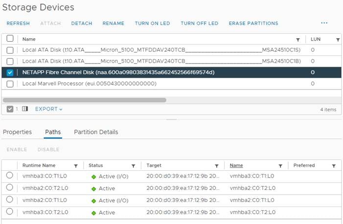
VMware ESXi 7.0 U2 TPM Attestation
If your Cisco UCS servers have Trusted Platform Module (TPM) 2.0 modules installed, the TPM can provide assurance that ESXi has booted with UEFI Secure Boot enabled and using only digitally signed code. In the Cisco UCS Configuration section of this document, UEFI secure boot was enabled in the boot policy. A server can boot with UEFI Secure Boot with or without a TPM 2.0 module. If it has a TPM, VMware vCenter can attest that the server booted with UEFI Secure Boot. To configure the Vmware ESXi 7.0 U2 TPM, follow these steps:
1. If your Cisco UCS servers have TPM 2.0 modules installed, TPM Attestation can be verified in the vSphere HTML5 Client.
2. From the Hosts and Clusters window in the vSphere Client, click the FlexPod-Management cluster. In the center pane, click Monitor > Security. The Attestation status will appear as shown below, where 2 of the 3 hosts have TPM 2.0 modules installed:
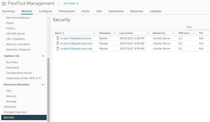
![]() It may be necessary to disconnect and reconnect a host from vCenter to get it to pass attestation the first time.
It may be necessary to disconnect and reconnect a host from vCenter to get it to pass attestation the first time.
Storage Configuration – ONTAP NVMe Namespace Mapping and Finalizing ONTAP Storage
Ansible Configuration
This section details the Ansible Scripts used to configure storage.
To configure storage, follow these steps:
1. Edit the following variable file and update the nvme_specs variable with namespace and subsystem info:
FlexPod-M6/FlexPod-UCSM-M6/vars/ontap_main.yml
![]() Add the NQNs from each host to the subsystem variable. The NVMe namespace will be shared by all the hosts in the nvme subsystem.
Add the NQNs from each host to the subsystem variable. The NVMe namespace will be shared by all the hosts in the nvme subsystem.
2. From /root/ FlexPod-M6/FlexPod-UCSM-M6, invoke the ansible scripts for this section using the following command:
ansible-playbook -i inventory Setup_ONTAP.yml -t ontap_config_part_3
![]() Use the -vvv tag to see detailed execution output log.
Use the -vvv tag to see detailed execution output log.
Manual Configuration
1. Create NVMe namespace:
vserver nvme namespace create -vserver SVM_name -path path -size size_of_namespace -ostype OS_type
aa16-a400::> vserver nvme namespace create -vserver Infra-SVM -path /vol/NVMe_datastore_01/NVMe_namespace_01 -ostype vmware -size 50G
Created a namespace of size 50GB (53687091200).
2. Create NVMe subsystem:
vserver nvme subsystem create -vserver SVM_name -subsystem name_of_subsystem -ostype OS_type
aa16-a400::> vserver nvme subsystem create -vserver Infra-SVM -subsystem nvme_infra_host_01_02_03 -ostype vmware
3. Verify the subsystem was created:
vserver nvme subsystem show -vserver SVM_name
aa16-a400::> vserver nvme subsystem show -vserver Infra-SVM
Vserver Subsystem Target NQN
------- ------------ --------------------------------------------------------
Infra-SVM
nvme_infra_host_01_02_03
nqn.1992-08.com.netapp:sn.e01bbb1de4f911ebac6fd039ea166b8c:subsystem. nvme_infra_host_01_02_03
Configure NVMe over FC on ESXi Host
Execute the following steps whether the Ansible configuration or manual configuration was used to set up the NVME namespace and subsystem. To configure NVMe over FC on the ESXi host, follow these steps:
1. Enabling NVMe/FC with ANA:
esxcfg-advcfg -s 0 /Misc/HppManageDegradedPaths
Reboot the Host
After reboot, verify that the HppManageDegradedPaths parameter is now disabled:
esxcfg-advcfg -g /Misc/HppManageDegradedPaths
The Value of HppManageDegradedPaths is 0
2. Get the ESXi host NQN string and add this to the host NQN string for the corresponding subsystem on the ONTAP array:
esxcli nvme info get
3. Add the host NQNs to the subsystem. This information is obtained in Step 2 for Configuring NVME:
vserver nvme subsystem host add -vserver SVM_name -subsystem Subsystem_name -host-nqn Host_NQN:subsystem.Subsystem_name
aa16-a400::> vserver nvme subsystem host add -vserver Infra_SVM -subsystem nvme_infra_host_01_02_03 -host-nqn nqn.2014-08.com.cisco.flexpod:nvme:nx-esxi-1
aa16-a400::> vserver nvme subsystem host add -vserver Infra_SVM -subsystem nvme_infra_host_01_02_03 -host-nqn nqn.2014-08.com.cisco.flexpod:nvme:nx-esxi-2
aa16-a400::> vserver nvme subsystem host add -vserver Infra_SVM -subsystem nvme_infra_host_01_02_03 -host-nqn nqn.2014-08.com.cisco.flexpod:nvme:nx-esxi-3
aa16-a400::> vserver nvme subsystem host show
Vserver Subsystem Host NQN
------- --------- ----------------------------------------------------------
Infra_SVM
nvme_infra_host_01_02_03
nqn.2014-08.com.cisco.flexpod:nvme:nx-esxi-1
nqn.2014-08.com.cisco.flexpod:nvme:nx-esxi-2
nqn.2014-08.com.cisco.flexpod:nvme:nx-esxi-3
3 entries were displayed.
![]() It is important that the separate host NQNs get added in separate commands and not as a comma-separated list in a single command. If a comma-separated list in a single command is entered, ONTAP will take the input as a single, long NQN and will not indicate an error. Also, the ESXi hosts will not map the namespaces mapped to this subsystem.
It is important that the separate host NQNs get added in separate commands and not as a comma-separated list in a single command. If a comma-separated list in a single command is entered, ONTAP will take the input as a single, long NQN and will not indicate an error. Also, the ESXi hosts will not map the namespaces mapped to this subsystem.
4. Map the Namespace to the subsystem:
vserver nvme subsystem map add -vserver SVM_name -subsystem subsystem_name -path path
aa16-a400::> vserver nvme subsystem map add -vserver Infra_SVM -subsystem nvme_infra_host_01_02_03 -path /vol/NVMe_datastore_01/NVMe_namespace_01
5. Verify the Namespace is mapped to the subsystem:
vserver nvme subsystem map show -vserver Infra-SVM -instance
6. Reboot each ESXi host and then verify that the ONTAP target NVMe/FC controllers are properly discovered on the ESXi Host:
esxcli nvme controller list
[root@nx-esxi-1:~] esxcli nvme controller list
Name Controller Number Adapter Transport Type Is Online
--------------------------------------------------------------------------------------------------------------------------------- ----------------- ------- -------------- ---------
nqn.1992-08.com.netapp:sn.50919001efe111ebb785d039ea166b8c:subsystem.nvme_infra_host_01#vmhba65#2005d039ea17129b:2006d039ea17129b 258 vmhba65 FC true
nqn.1992-08.com.netapp:sn.50919001efe111ebb785d039ea166b8c:subsystem.nvme_infra_host_01#vmhba64#2005d039ea17129b:2007d039ea17129b 261 vmhba64 FC true
nqn.1992-08.com.netapp:sn.50919001efe111ebb785d039ea166b8c:subsystem.nvme_infra_host_01#vmhba65#2005d039ea17129b:2008d039ea17129b 265 vmhba65 FC true
nqn.1992-08.com.netapp:sn.50919001efe111ebb785d039ea166b8c:subsystem.nvme_infra_host_01#vmhba64#2005d039ea17129b:2009d039ea17129b 266 vmhba64 FC true
Configure DNS
To configure DNS for the Infra_SVM, run the following commands:
dns create -vserver <vserver name> -domains <dns-domain> -nameserve <dns-servers>
dns create -vserver Infra_SVM -domains flexpod.cisco.com -nameservers 10.1.156.250,10.1.156.251
Delete Residual Default Broadcast Domains (Applicable for 2-node cluster only)
To delete the Default broadcast domains that are not in use, run the following commands:
broadcast-domain delete -broadcast-domain <broad-domain-name>
broadcast-domain delete -broadcast-domain Default-1
Test AutoSupport
To test the AutoSupport configuration by sending a message from all nodes of the cluster, run the following commands:
autosupport invoke -node * -type all -message “FlexPod storage configuration completed”
ESXi Host NVMe over FC Datastore Configuration
To configure the ESXi host NVMe over FC datastore, follow these steps:
1. The remaining steps in the VMware vSphere Client are manual steps that should be completed whether Ansible configuration or manual configuration is being done. Verify that the NVMe Fibre Channel Disk is mounted on each ESXi host. Under Hosts and Clusters select the ESXi host. In the center pane, select Configure > Storage > Storage Devices. The NVMe Fibre Channel Disk should be listed under Storage Devices. Select the NVMe Fibre Channel Disk, then select Paths underneath. Verify 2 paths have a status of Active (I/O) and 2 paths have a status of Active.
2. Repeat this step for all 3 hosts.
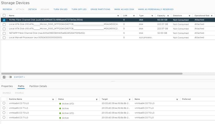
3. For any of the three hosts, right-click the host under Hosts and Clusters and select Storage > New Datastore. Leave VMFS selected and click NEXT.
4. Name the datastore and select the NVMe Fibre Channel Disk. Click NEXT.
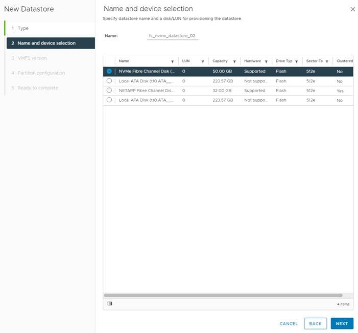
5. Leave VMFS 6 selected and click NEXT.
6. Leave all Partition configuration values at the default values and click NEXT.
7. Review the information and click FINISH.
8. Select Storage and select the just-created NVMe datastore. In the center pane, select Hosts. Ensure all three hosts have the datastore mounted.
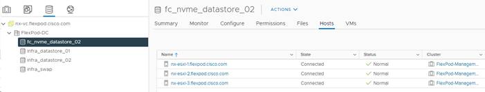
FlexPod Management Tools Setup
Cisco UCS Manager Plug-in for VMware vSphere Web Client
The Cisco UCS Manager Plug-in for VMware vSphere Web Client allows administration of UCS domains through the VMware vCenter administrative interface. The capabilities of the plug-in include:
● Cisco UCS physical hierarchy view
● Overall health of server and other infrastructure components
● Maps UCS servers to ESX hosts
● Inventory, installed firmware, faults, power, and temperature statistics for each server/ESX host
● KVM launch for all ESX and non-ESX servers
● Switch on and off locater LED and launch Cisco UCS Manager GUI for each server
● Registration tool for registering the plug-in with the vCenter
● Perform key actions on ESX, non-ESX servers, and other UCS components
● View service profile, service profile templates, server pools, and host firmware packs for each UCS Domain
● Server firmware management using host firmware pack
● Support for VMware vSphere HTML client 6.7 and later
● Firmware Management for blades and rack servers in UCS domain. You can perform the following operations:
● Upload firmware
● Modify firmware package version for the host firmware packs with option to move the affected ESX host into maintenance mode before triggering the firmware upgrade
● Acknowledge pending activities
● Delete firmware package
● Delete firmware upload task
● View VIF paths for servers
● Monitor UCS domain, chassis, fabric interconnect, fabric extender, ESX, and non-ESX servers
● View faults with ability to filter based on the severity
● Support for In-Band access with IPv4, and IPv6 addresses
● Managing of UCS domains using IPv6 addresses
● Enhancement to allow registered domains to be globally visible
● Support for Proactive High Availability (HA)—The Cisco UCS Provider supports the Proactive HA feature which allows you to protect the hosts within a vCenter cluster from potential failures
The installation is only valid for VMware vCenter 6.7 or higher and will require revisions of .NET Framework 4.5 or higher, and VMware PowerCLI 5.1 or higher.
Cisco UCS Manager Plug-in Installation
To begin the plug-in installation on a Windows system that meets the previously stated requirements, follow these steps:
1. Download the plugin and registration tool from: https://software.cisco.com/download/home/286282669/type/286282010/release/3.0.5.
2. Place the downloaded ucs-vcplugin-html-3.0.5.zip file onto the web server used for hosting the ONTAP software, VMware ESXi ISO, and VMware ESXi drivers.
3. Unzip the Cisco_UCS_Plugin_Registration_Tool_v1-2-3.zip and open the executable file within it.
4. Leave Register Plugin selected for the Action, fill in the following vCenter information and click Submit:
a. IP/Hostname
b. Username (administrator@vsphere.local)
c. Password
d. URL that plugin has been uploaded to
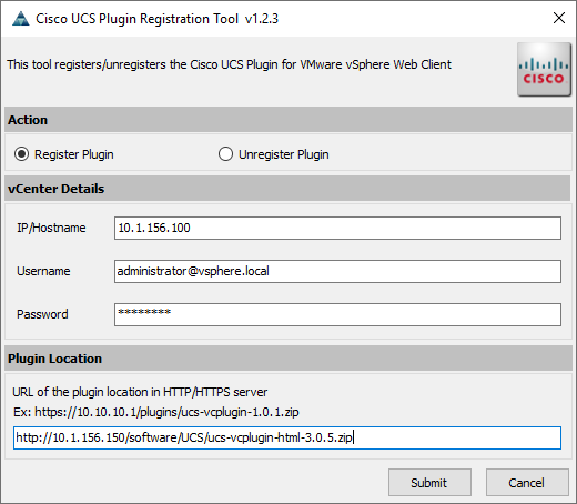
5. A pop-up will appear explaining that ‘allowHttp=true’ will need to be added to the webclient.properties file on the VCSA in the /etc/vmware/vsphere-ui directory.
6. This issue will be resolved after the plugin has been registered, click OK to close the Information dialogue box.
7. Click OK to confirm that the Cisco UCS Plugin registered successfully.
8. Click Cancel to close the registration tool.
9. To resolve the change needed for the HTTP download of the vSphere Web Client launch, connect to the VCSA with ssh using the root account, open the BASH shell, and type:
echo ‘allowHttp=true’ >> /etc/vmware/vsphere-ui/webclient.properties
![]() This will add “allowHttp=true” to the end of the webclient.properties file. Make sure to use two greater than symbols “>>” to append to the end of the configuration file, a single greater than symbol will replace the entire pre-existing file with what has been sent with the echo command.
This will add “allowHttp=true” to the end of the webclient.properties file. Make sure to use two greater than symbols “>>” to append to the end of the configuration file, a single greater than symbol will replace the entire pre-existing file with what has been sent with the echo command.
10. To verify the change, type the following. If allowHttp=true is not on the last line of the file by itself, use an editor such as vim to fix this and make allowHttp=true the last line of the file:
cat /etc/vmware/vsphere-ui/webclient.properties
11. Logout and log back into the vSphere Client.
FlexPod UCS Domain Registration
You can now register the FlexPod UCS Domain. The account used will correlate to the permissions allowed to the plugin, admin will be used in our example, but a read only account could be used with the plugin if that was appropriate for the environment.
To register the UCS Domain, follow these steps:
1. Open the vSphere Client.
2. Select the Menu drop-down list and select the Cisco UCS icon.
3. Click Register and provide the following options in the Register UCS Domain dialogue box that appears:
a. UCS Hostname/IP
b. Username
c. Password
d. Port (if different than 443)
e. Leave SSL selected and click the Visible to All users option
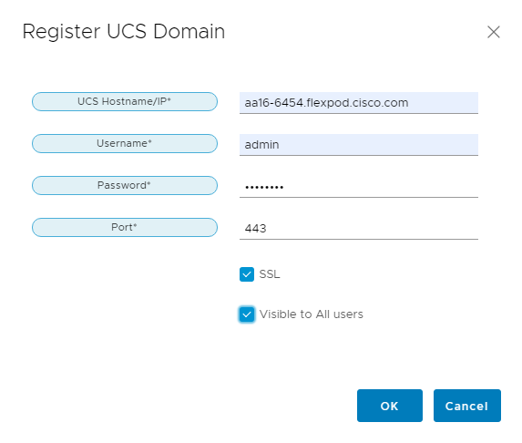
4. Click OK then click OK again to register the UCS Domain.
Use the Cisco UCS vCenter Plugin
The plugin can now enable the functions described at the start of this section by double-clicking the registered UCS Domain:
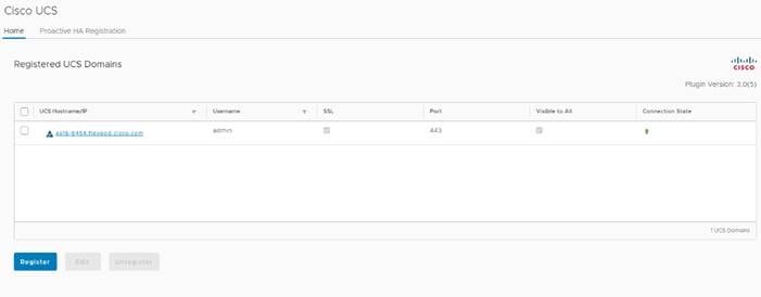
You can view the components associated to the domain:
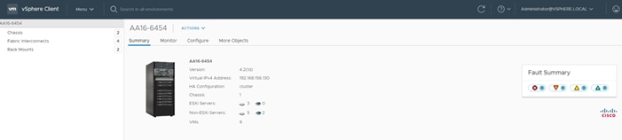
Selecting within the chassis or rack mounts will provide a list of ESXi or non-ESXi servers to perform operations on the following:
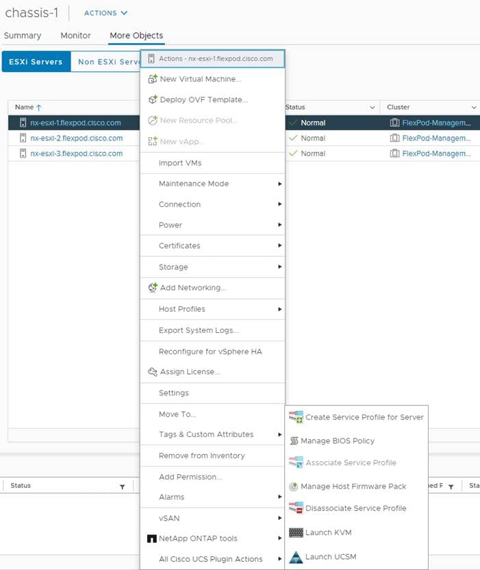
In addition to viewing and working within objects shown in the UCS Plugin’s view of the UCS Domain, direct access of Cisco UCS functions provided by the plugin can be selected within the drop-down list of hosts registered to vCenter.
For full installation instructions and usage information, please refer to the Cisco UCS Manager Plug-in for VMware vSphere Web Client User Guide at: https://www.cisco.com/c/en/us/td/docs/unified_computing/ucs/sw/vmware_tools/vCenter/vCenter_Plugin_User_Guide/3x/b_UCSM_Plugin_VMware_vSphere_Web_Client_User_Guide_3_x.html.
NetApp ONTAP Tools 9.8P2 Deployment Procedure
The ONTAP tools for VMware vSphere provide end-to-end life cycle management for virtual machines in VMware environments that use NetApp storage systems. It simplifies storage and data management for VMware environments by enabling administrators to directly manage storage within the vCenter Server.
This section describes the deployment procedures for the NetApp ONTAP Tools for VMware vSphere.
NetApp ONTAP Tools for VMware vSphere 9.8P2 Pre-installation Considerations
The following licenses are required for ONTAP Tools on storage systems that run ONTAP 9.8 or above:
● Protocol licenses (NFS, FCP, and/or iSCSI)
● NetApp FlexClone® ((optional) Required for performing test failover operations for SRA and for
vVols operations of VASA Provider.
● NetApp SnapRestore® (for backup and recovery)
● The NetApp SnapManager® Suite
● NetApp SnapMirror® or NetApp SnapVault® ((optional) Required for performing failover operations for SRA and VASA Provider if u using vVols replication.)
![]() The Backup and Recovery capability has been integrated with SnapCenter and requires additional licenses for SnapCenter to perform backup and recovery of virtual machines and applications.
The Backup and Recovery capability has been integrated with SnapCenter and requires additional licenses for SnapCenter to perform backup and recovery of virtual machines and applications.
Table 8. Port Requirements for NetApp ONTAP Tools
| Port |
Requirement |
| 443 (HTTPS) |
Secure communications between VMware vCenter Server and the storage systems |
| 8143 (HTTPS) |
VSC listens for secure communications |
| 9083 (HTTPS) |
VASA Provider uses this port to communicate with the vCenter Server and obtain TCP/IP settings |
| 7 |
VSC sends an echo request to ONTAP to verify reachability and is required only when adding storage system and can be disabled later. |
![]() NetApp ONTAP Tools can be installed using the ansible scripts.
NetApp ONTAP Tools can be installed using the ansible scripts.
To invoke the ansible scripts use the following command:
ansible-playbook -i inventory Setup_ONTAP_tools.yml
Update the following variable files:
vars/ontap_tools_main.yml
group_vars/vcenter
To install the NetApp ONTAP tools for VMware vSphere 7.0U2 software by using an Open Virtualization Format (OVF) deployment, follow these steps:
1. Launch the vSphere Web Client and navigate to Hosts and Clusters.
2. Select ACTIONS for the FlexPod-DC datacenter and choose Deploy OVF Template.
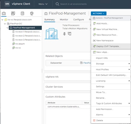
3. Browse to the ONTAP tools file downloaded from the NetApp Support site.
4. Enter the VM name and choose a datacenter or folder in which to deploy and click NEXT.
5. Choose a host cluster resource in which to deploy OVA and click NEXT.
6. Review the details and accept the license agreement.
7. Choose the infra_datastore_02 volume and choose the Thin Provision option for the virtual disk format.
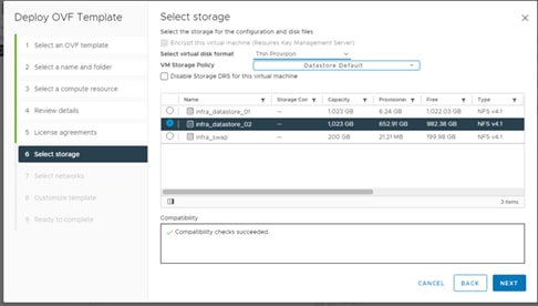
8. From Select Networks, choose a destination network (IB-MGMT Network) and click NEXT.
9. From Customize Template, enter the ONTAP tools administrator password, vCenter name or IP address and other configuration details and click NEXT.
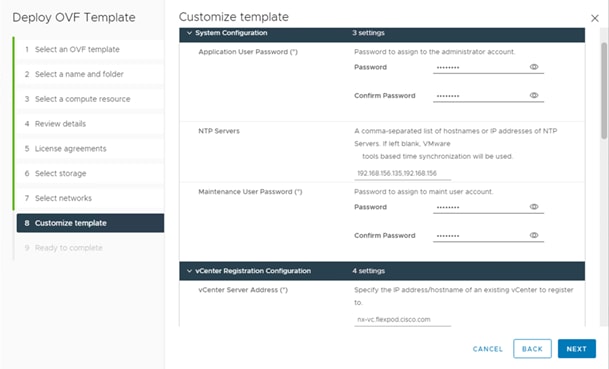
10. Review the configuration details entered and click FINISH to complete the deployment of NetApp ONTAP-tools VM.
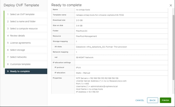
11. Power on the ONTAP-tools VM and open the VM console.
12. During the ONTAP-tools VM boot process, you see a prompt to install VMware Tools. From vCenter, right-click the ONTAP-tools VM > Guest OS > Install VMware Tools.
13. Networking configuration and vCenter registration information was provided during the OVF template customization, therefore after the VM is running, VSC and vSphere API for Storage Awareness (VASA) is registered with vCenter.
14. Refresh the Home Screen and confirm that the ONTAP tools is installed.
![]() The NetApp ONTAP tools vCenter plug-in is only available in the vSphere HTML5 Client and is not available in the vSphere Web Client.
The NetApp ONTAP tools vCenter plug-in is only available in the vSphere HTML5 Client and is not available in the vSphere Web Client.
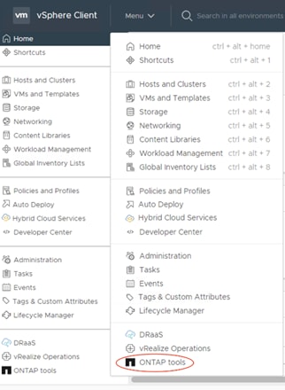
Download the NetApp NFS Plug-in for VAAI
To download the NetApp NFS Plug-in for VAAI, follow this step:
1. Download the NetApp NFS Plug-in 2.0 for VMware .vib file from the NFS Plugin Download page and save it to your local machine or admin host.
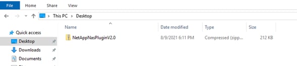
Install the NetApp NFS Plug-in for VAAI
![]() The NFS Plug-in for VAAI was previously installed on the ESXi hosts along with the Cisco UCS VIC drivers; it is not necessary to re-install.
The NFS Plug-in for VAAI was previously installed on the ESXi hosts along with the Cisco UCS VIC drivers; it is not necessary to re-install.
To install the NetApp NFS Plug-in for VAAI, follow these steps:
1. Rename the .vib file that you downloaded from the NetApp Support Site to NetAppNasPlugin.vib to match the predefined name that ONTAP tools uses.
2. Click Settings in the ONTAP tool Getting Started page.
3. Click NFS VAAI Tools tab.
4. Click Change in the Existing version section.
5. Browse and choose the renamed .vib file, and then click Upload to upload the file to the virtual appliance.
6. In the Install on ESXi Hosts section, choose the ESXi host on which you want to install the NFS Plug-in for VAAI, and then click Install.
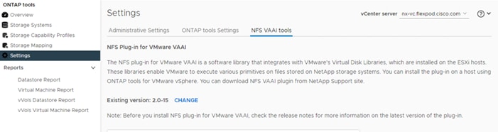
7. Reboot the ESXi host after the installation finishes.
The VASA provider for ONTAP is enabled by default during the installation of the NetApp ONTAP tools. To verify the VASA provider was enabled, follow these steps:
1. From the vSphere Client, click Menu > ONTAP tools.
2. Click Settings.
3. Click Manage Capabilities in the Administrative Settings tab.
4. In the Manage Capabilities dialog box if not enabled, click Enable VASA Provider slider.
5. Enter the IP address of the virtual appliance for ONTAP tools, VASA Provider, and VMware Storage Replication Adapter (SRA) and the administrator password, and then click Apply.
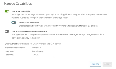
Discover and Add Storage Resources
To Add storage resources for the Monitoring and Host Configuration capability and the Provisioning and Cloning capability, follow these steps:
1. Using the vSphere Web Client, log in to the vCenter Server as the FlexPod admin user. If the vSphere Web Client was previously opened, close the tab, and then reopen it.
2. In the Home screen, click the Home tab and click ONTTAP tools.
![]() When using the cluster admin account, add storage from the cluster level.
When using the cluster admin account, add storage from the cluster level.
![]() You can modify the storage credentials with the vsadmin account or another SVM level account with role-based access control (RBAC) privileges. Refer to the ONTAP 9 Administrator Authentication and RBAC Power Guide for additional information.
You can modify the storage credentials with the vsadmin account or another SVM level account with role-based access control (RBAC) privileges. Refer to the ONTAP 9 Administrator Authentication and RBAC Power Guide for additional information.
3. Choose Storage Systems >Add
4. Click Overview > Getting Started, and then click ADD under Add Storage System.
5. Specify the vCenter Server instance where the storage will be located.
6. In the IP Address/Hostname field, enter the storage cluster management IP.
7. Confirm Port 443 to Connect to this storage system.
8. Enter admin for the username and the admin password for the cluster.
9. Click Save to add the storage configuration to ONTAP tools.
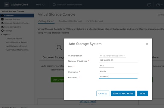
10. Wait for the Storage Systems to update. You might need to click Refresh to complete this update.
To discover the cluster and SVMs with the cluster admin account, follow these steps:
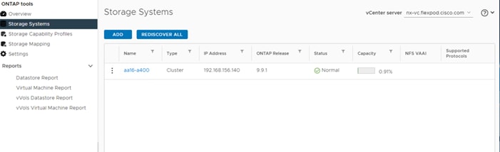
1. From the vSphere Client Home page, click Hosts and Clusters.
2. Right-click the FlexPod-DC datacenter, click NetApp ONTAP tools > Update Host and Storage Data.
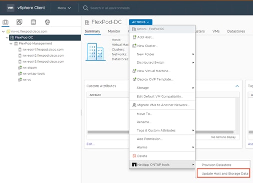
NetApp ONTAP tools displays a Confirm dialog box that informs you that this operation might take a few minutes.
3. Click OK.
Optimal Storage Settings for ESXi Hosts
ONTAP tools enables the automated configuration of storage-related settings for all ESXi hosts that are connected to NetApp storage controllers. To use these settings, follow these steps:
1. From the VMware vSphere Web Client Home page, click vCenter > Hosts.
2. Choose a host and then click Actions > NetApp ONTAP tools > Set Recommended Values.
3. In the NetApp Recommended Settings dialog box, choose all the values for your system.
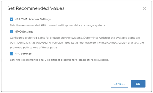
![]() This functionality sets values for HBAs and converged network adapters (CNAs), sets appropriate paths and path-selection plug-ins, and verifies appropriate settings for software-based I/O (NFS). A vSphere host reboot may be required after applying the settings.
This functionality sets values for HBAs and converged network adapters (CNAs), sets appropriate paths and path-selection plug-ins, and verifies appropriate settings for software-based I/O (NFS). A vSphere host reboot may be required after applying the settings.
4. Click OK.
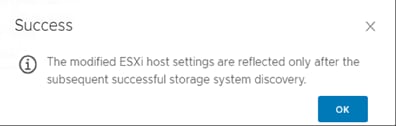
ONTAP Tools 9.8P2 Provisioning Datastores
Using ONTAP tools, the administrator can provision an NFS, FC, FC-NVMe or iSCSI datastore and attach it to a single host or multiple hosts in the cluster. The following steps describe provisioning a datastore and attaching it to the cluster.
![]() It is a NetApp best practice to use ONTAP tools to provision datastores for the FlexPod infrastructure. When using VSC to create vSphere datastores, all NetApp storage best practices are implemented during volume creation and no additional configuration is needed to optimize performance of the datastore volumes.
It is a NetApp best practice to use ONTAP tools to provision datastores for the FlexPod infrastructure. When using VSC to create vSphere datastores, all NetApp storage best practices are implemented during volume creation and no additional configuration is needed to optimize performance of the datastore volumes.
Storage Capabilities
A storage capability is a set of storage system attributes that identifies a specific level of storage performance (storage service level), storage efficiency, and other capabilities such as encryption for the storage object that is associated with the storage capability.
Create the Storage Capability Profile
In order to leverage the automation features of VASA two primary components must first be configured. The Storage Capability Profile (SCP) and the VM Storage Policy. The Storage Capability Profile expresses a specific set of storage characteristics into one or more profiles used to when provisioning a Virtual Machine. The SCP is specified as part of VM Storage Policy which is specified when you deploy a virtual machine. NetApp Virtual Storage Console comes with two pre-configured Storage Capability Profiles- Platinum and Bronze.
![]() The ONTAP tools for VMware vSphere plug-in also allow you to set Quality of Service (QoS) rule using a combination of maximum and/or minimum IOPs.
The ONTAP tools for VMware vSphere plug-in also allow you to set Quality of Service (QoS) rule using a combination of maximum and/or minimum IOPs.
To review or edit one of the built-in profiles pre-configured with ONTAP tools, follow these steps:
1. In the NetApp ONTAP tools click Storage Capability Profiles.
2. Choose the Platinum Storage Capability Profile and choose Clone from the toolbar.
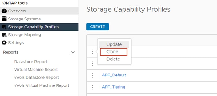
3. Enter a name for the cloned SCP and add a description if desired.
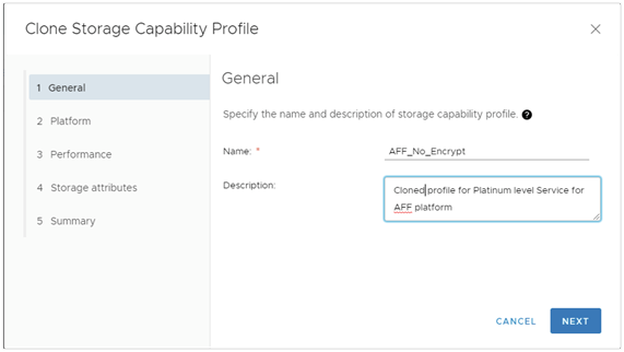
4. Choose All Flash FAS(AFF) for the storage platform and click Next.
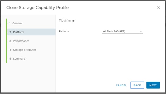
5. Choose None to allow unlimited performance or set a the desired minimum and maximum IOPS for the QoS policy group.
6. On the Storage attributes page, Change the Encryption and Tiering policy to the desired settings and click NEXT.
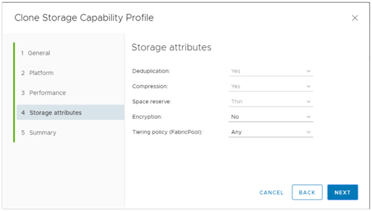
7. Review the summary page and choose FINISH to create the storage capability profile.
![]() It is recommended to Clone the Storage Capability Profile if you wish to make any changes to the default profiles rather than editing the built-in profile.
It is recommended to Clone the Storage Capability Profile if you wish to make any changes to the default profiles rather than editing the built-in profile.
Create a VM storage policy and associate a storage capability profile (SCP) to the datastore that meets the requirements defined in the SCP. To create a new VM Storage policy, follow these steps:
1. Navigate to Policies and Profiles from the vSphere Client menu.
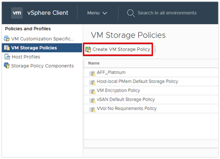
2. Choose VM Storage Policies and click Create VM Storage Policy.
3. Create a name for the VM storage policy and enter a description and click NEXT.
4. Choose Enable rules for NetApp.clustered.Data.ONTAP.VP.VASA10 storage located under the Datastore specific rules section and click NEXT.
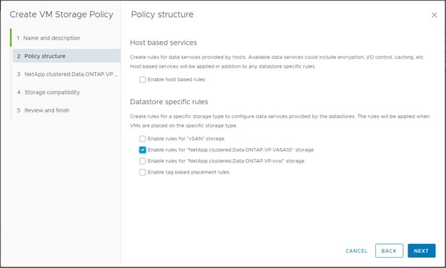
5. On the Placement tab select the SCP created in the previous step and click NEXT.
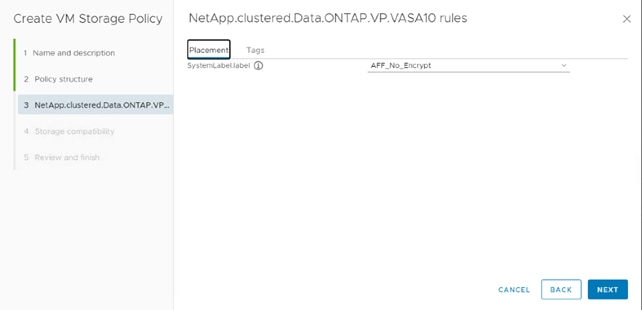
6. The datastores with matching capabilities are displayed, click NEXT.
7. Review the policy summary and click FINISH.
Provision NFS Datastore
To provision the NFS datastore, follow these steps:
1. From the ONTAP tools Home page, click Overview.
2. In the Getting Started tab, click Provision.
3. Click Browse to choose the destination to provision the datastore.
4. Choose the type as NFS and Enter the datastore name.
5. Provide the size of the datastore and the NFS Protocol.
6. Check the storage capability profile and click NEXT.
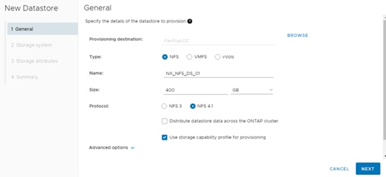
7. Choose the desired Storage Capability Profile, cluster name and the desired SVM to create the datastore. In this example, the Infra-SVM is selected.
8. Click NEXT.
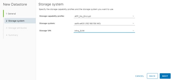
9. Choose the aggregate name and click NEXT.
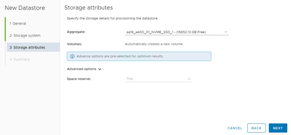
10. Review the Summary and click FINISH.
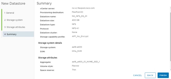
![]() The datastore is created and mounted on the hosts in the cluster. Click Refresh from the vSphere Web Client to see the newly created datastore or it is also listed in the ONTAP tools home page > Traditional Dashboard > Datastores view. Also, ONTAP tools home page > Reports > Datastore Report should list the newly created datastore.
The datastore is created and mounted on the hosts in the cluster. Click Refresh from the vSphere Web Client to see the newly created datastore or it is also listed in the ONTAP tools home page > Traditional Dashboard > Datastores view. Also, ONTAP tools home page > Reports > Datastore Report should list the newly created datastore.
11. Distributed datastore is supported from ONTAP 9.8, which provides FlexGroup volume on ONTAP storage. To create a Distributed Datastore across the ONTAP Cluster select NFS 4.1 and check the box for Distributed Datastore data across the ONTAP Cluster.
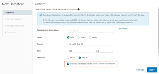
12. Provide the Storage System details and SVM name. Click Next.
13. The storage attributes are assigned automatically. Select the space reserve option by clicking Advanced options. Click Next.
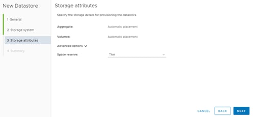
14. Review the summary and click Finish.
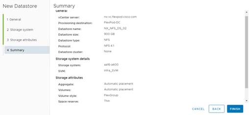
Provision FC Datastore
To provision the FC datastore, follow these steps:
1. From the ONTAP tools Home page, click Overview.
2. In the Getting Started tab, click Provision.
3. Click Browse to choose the destination to provision the datastore.
4. Choose the type as VMFS and Enter the datastore name.
5. Provide the size of the datastore and the FC Protocol.
6. Check the storage capability profile and click NEXT.
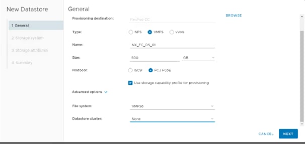
7. Choose the Storage Capability Profile, cluster name and the desired SVM to create the datastore. In this example, the Infra-SVM is selected.
8. Click NEXT.

9. Choose the aggregate name and click NEXT.
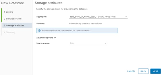
10. Review the Summary and click FINISH.

11. Click OK.
![]() The datastore is created and mounted on all the hosts in the cluster. Click Refresh from the vSphere Web Client to see the newly created datastore or it is also listed in the ONTAP tools home page > Traditional Dashboard > Datastores view. Also, ONTAP tools Home page > Reports > Datastore Report should be listing the newly created datastore.
The datastore is created and mounted on all the hosts in the cluster. Click Refresh from the vSphere Web Client to see the newly created datastore or it is also listed in the ONTAP tools home page > Traditional Dashboard > Datastores view. Also, ONTAP tools Home page > Reports > Datastore Report should be listing the newly created datastore.
Create Virtual Machine with Assigned VM Storage Policy
To create a virtual machine assigned to a VM storage policy, follow these steps:
1. Navigate to the VMs and Templates tab and click the FlexPod-DC datacenter.
2. Click Actions and click New Virtual Machine.
3. Choose Create a new virtual machine and choose NEXT.
4. Enter a name for the VM and click the FlexPod-DC datacenter.
5. Choose the FlexPod-Management Data compute Resource.
6. Choose the VM storage policy from the selections and choose a compatible datastore and click NEXT.
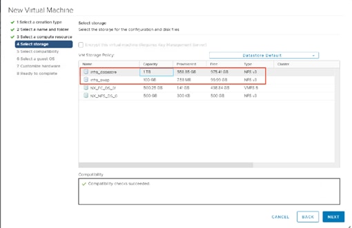
7. Choose Compatibility and click NEXT.
8. Choose the Guest OS and click NEXT.
9. Customize the hardware for the VM and click NEXT.
10. Review the details and click FINISH.
NetApp VASA Provider enables you to create and manage VMware virtual volumes (vVols). A vVols datastore consists of one or more FlexVol volumes within a storage container (also called "backing storage"). A virtual machine can be spread across one vVols datastore or multiple vVols datastores. All of the FlexVol volumes within the storage container must use the same protocol (NFS, iSCSI, or FCP) and the same SVMs.
![]() Lab testing has shown that if a virtual machine (VM) has one or more disks in vVol datastores and the VM is migrated to another host, just at the end of the migration the VM can be stunned or frozen for 45 or more seconds.
Lab testing has shown that if a virtual machine (VM) has one or more disks in vVol datastores and the VM is migrated to another host, just at the end of the migration the VM can be stunned or frozen for 45 or more seconds.
Verify NDMP Vserver Scope Mode
To verify the NDMP Vserver scope mode, follow these steps:
1. View NDMP scope mode with the following command:
system services ndmp node-scope-mode status
NDMP node-scope-mode is enabled.
2. Disable NDMP node-scoped mode:
system services ndmp node-scope-mode off
NDMP node-scope-mode is disabled.
3. Enable NDMP services on the vserver:
vserver add-protocols -protocols ndmp -vserver Infra_svm
vserver services ndmp on -vserver Infra_svm
Create the Storage Capability Profile
You can select one or more VASA Provider storage capability profiles for a vVols datastore. You can also specify a default storage capability profile for any vVols datastores that are automatically created in that storage container.
To create storage capability profile for the vVol datastore, follow these steps:
1. In the NetApp ONTAP tools click Storage Capability Profiles.
2. Choose the Platinum Storage Capability Profile and choose Clone from the toolbar.
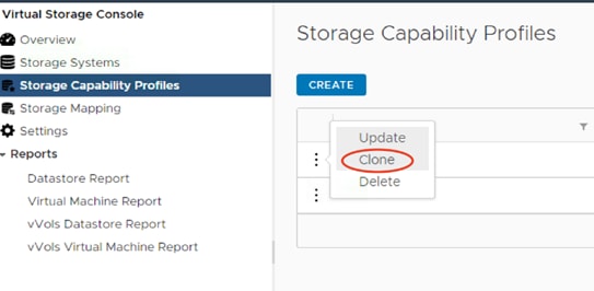
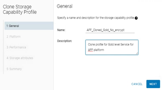
3. Choose All Flash FAS(AFF) for the storage platform and click Next.
4. Choose None to allow unlimited performance or set a the desired minimum and maximum IOPS for the QoS policy group. You can set the value for Max IOPS, which enables you to use the QoS functionality.
![]() When applied for a virtual datastore, a QoS policy with "MAX IOPS" value is created for each data vVols.
When applied for a virtual datastore, a QoS policy with "MAX IOPS" value is created for each data vVols.
![]() When you select ONTAP Service Level, then the existing adaptive QoS policies of ONTAP are applied to a data vVols. You can select one of three service levels: Extreme, Performance, or Value. The ONTAP service level is applicable only to vVols datastores.
When you select ONTAP Service Level, then the existing adaptive QoS policies of ONTAP are applied to a data vVols. You can select one of three service levels: Extreme, Performance, or Value. The ONTAP service level is applicable only to vVols datastores.
5. On the Storage attributes page, change the Encryption and Tiering policy to the desired settings and click NEXT.

6. Review the summary page and choose FINISH to create the storage capability profile.
Create a VM storage policy and associate a storage capability profile (SCP) to the datastore that meets the requirements defined in the SCP. To create a new VM Storage policy, follow these steps:
1. Navigate to Policies and Profiles from the vSphere Client menu.
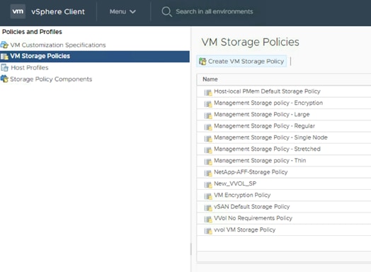
2. Click Create VM Storage Policy.
3. Create a new name for the VM storage Policy and enter a description and click NEXT.
4. Choose Enable rules for NetApp.clustered.Data.ONTAP.VP.VASA.10 storage and NetApp.clustered.Data.ONTAP.VP.vvol storage, located under the Datastore specific rules section and click NEXT.
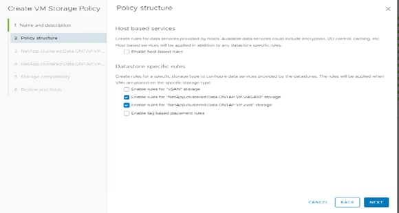
5. On the Placement tab for VP.VASA and VP.vvol storage rules, select the SCP created in the previous step.
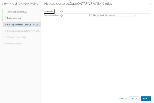
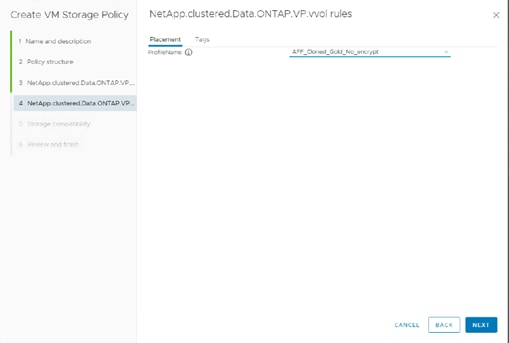
6. The datastores with matching capabilities are displayed, click NEXT.
7. Review the Policy Summary and click Finish.
To provision the vVols datastore over NFS protocol, follow these steps:
1. From the NetApp ONTAP tools Home page, click Overview.
2. In the Getting Started tab, click Provision.
3. Click Browse to choose the destination to provision the datastore as per the next step.
4. Choose the type as vVols and Enter the datastore name.
5. Select NFS for protocol and click Next.
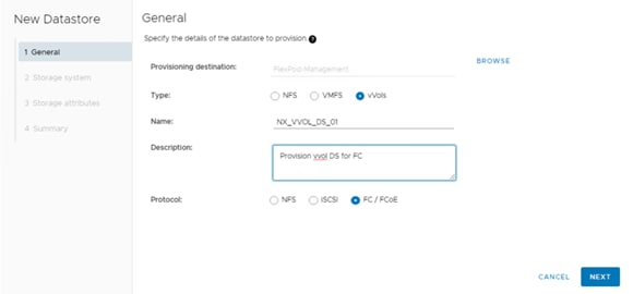
6. Select the Storage capability profile created earlier for vVols.
7. Select the NFS storage server and the NetApp Storage SVM where the vVols needs to be created and click Next.
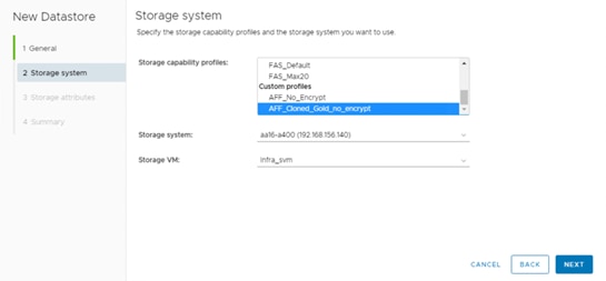
8. Create new vVols or select existing vVols.
![]() You can create multiple vVols for a datastore.
You can create multiple vVols for a datastore.
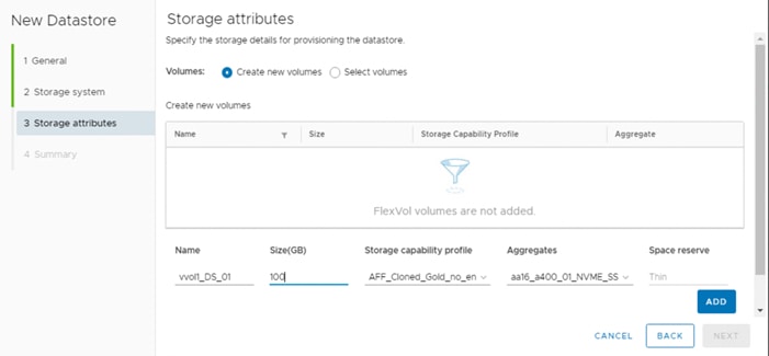
9. Check the storage capability profile and click NEXT.
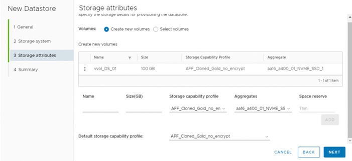
10. Review all the fields on the summary page and click Finish.
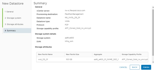
11. Verify in the vVols Datastore report the vVols is mounted correctly, go to VSC > Reports > vVols Datastore Report.
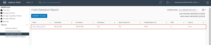
![]() To provision vVols for FC or ISCSI protocol, select it in the General tab and provide protocol-specific storage attributes in the Storage Attributes Inputs to create vVols successfully.
To provision vVols for FC or ISCSI protocol, select it in the General tab and provide protocol-specific storage attributes in the Storage Attributes Inputs to create vVols successfully.
The following actions can be performed on a vVols Datastore:
● Expand Storage on a vVols Datastore
● Remove Storage on a vVols Datastore
● Edit Properties of vVols Datastore
● Mount vVols Datastore
● Delete vVols Datastore
Expand Storage on a vVol Datastore
To expand storage on a vVol datastore, follow these steps:
1. In the Storage tab, click the vVols datastore to expand > Actions > NetApp ONTAP tools > Expand Storage on a vVols Datastore.
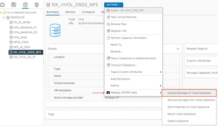
2. Provide the storage attributes. Create new vVols or select existing vVols. Click Add.
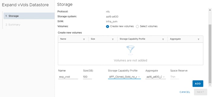
3. Review the details in the Summary page and click Finish.
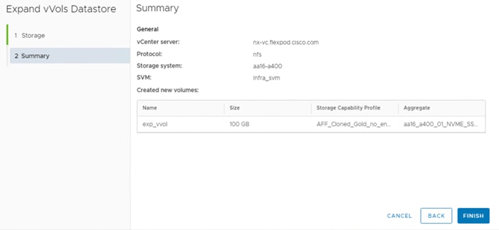
4. Verify that the size of the vVols datastore has been expanded successfully.
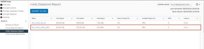
Remove Storage from a vVol Datastore
To remove storage from a vVol datastore, follow these steps:
1. In the Storage tab , click the vVol datastore to remove storage > Actions > NetApp VSC > Remove Storage from vVols Datastore.
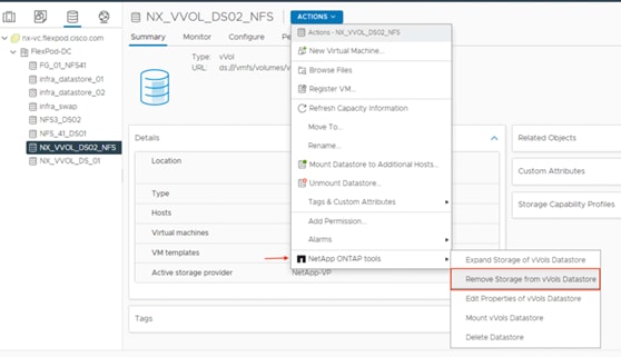
2. Select the vVols within the datastore to remove and click Remove.
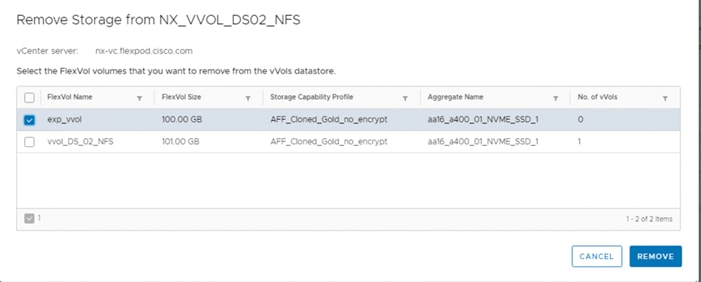
3. Verify the size of the datastore to validate the successful removal of storage from the vVols Datastore.
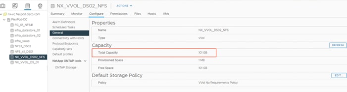
Create a Virtual Machine on a vVols Datastore with Assigned Virtual Machine Storage Policy
To provision a virtual machine on a vVols datastore, follow these steps:
1. Navigate to vSphere Client > VMs and Templates > Actions > New Virtual Machine.
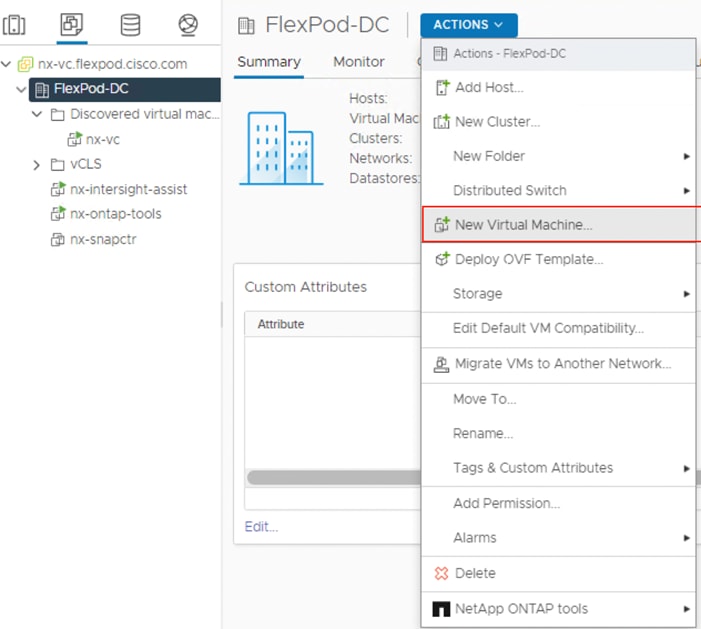
2. Enter the name for the VM and click the datacenter.
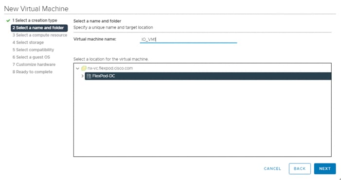
3. Choose the FlexPod-Management Data compute Resource.
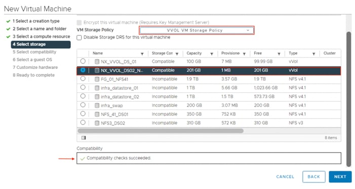
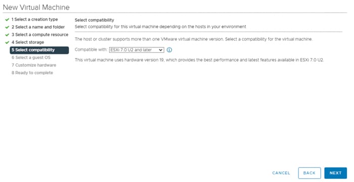
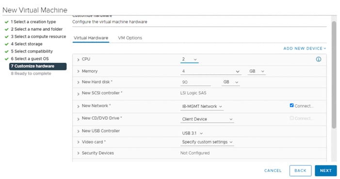
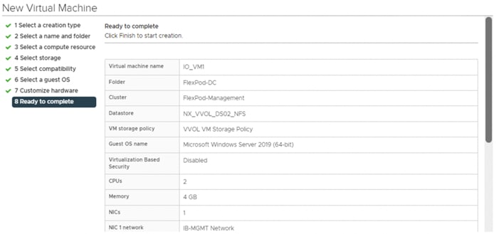
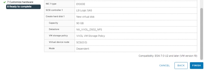
4. Validate that the VM is created successfully.
To monitor a vVols datastore, follow these steps:
1. The vVols dashboard in the NetApp ONTAP tools Overview tab provides:
● Overview
● Top 5 datastores by Space Utilization, IOPs and Latency in ascending and descending order
● A list of VMs on the vVols Datastore
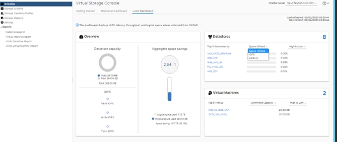
2. The vVol Datastore Report can be retrieved from VSC > Reports > vVol Datastore Report.
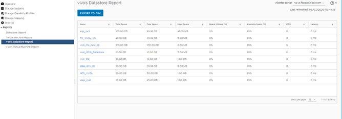
3. The vVol Virtual Machine Report can be retrieved from VSC > Reports > vVol Virtual Machine Report.
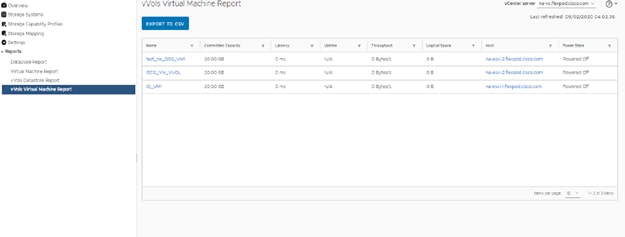
SnapCenter Software is a simple, centralized, scalable platform that provides application-consistent data protection for applications, databases, host file systems, and VMs running on ONTAP systems anywhere in the Hybrid Cloud.
NetApp SnapCenter Architecture
The SnapCenter platform is based on a multitier architecture that includes a centralized management server (SnapCenter Server) and a SnapCenter host agent. The host agent that performs virtual machine and datastore backups for VMware vSphere is the SnapCenter Plug-in for VMware vSphere. It is packaged as a Linux appliance (Debian-based Open Virtual Appliance format) and is no longer part of the SnapCenter Plug-ins Package for Windows. Additional information on deploying SnapCenter server for application backups can be found in the documentation listed below.
This guide focuses on deploying and configuring the SnapCenter plug-in for VMware vSphere to protect virtual machines and VM datastores.
You must install SnapCenter Server and the necessary plug-ins to support application-consistent backups for Microsoft SQL, Microsoft Exchange, Oracle databases and SAP HANA. Application-level protection is beyond the scope of this deployment guide. Refer to the SnapCenter documentation for more information or the application specific CVD’s and technical reports for detailed information on how to deploy SnapCenter for a specific application configuration.
● SnapCenter Documentation: https://docs.netapp.com/us-en/snapcenter/index.html
● FlexPod Datacenter for Microsoft SQL Server 2019 and VMware vSphere 6.7
● SnapCenter Plug-in for VMware vSphere Documentation
Install SnapCenter Plug-In for VMware vSphere 4.6
NetApp SnapCenter Plug-in for VMware vSphere is a Linux-based virtual appliance which enables the SnapCenter Plug-in for VMware vSphere to protect virtual machines and VMware datastores.
Host and Privilege Requirements for the SnapCenter Plug-In for VMware vSphere
Review the following requirements before you install the SnapCenter Plug-in for VMware vSphere virtual appliance:
● You must deploy the SnapCenter Plug-in for VMware vSphere virtual appliance as a Linux VM.
● You should deploy the virtual appliance on the vCenter Server.
● You must not deploy the virtual appliance in a folder that has a name with special characters.
● You must deploy and register a separate, unique instance of the virtual appliance for each vCenter Server.
Table 9. Port Requirements
| Port |
Requirement |
| 8080(HTTPS) bidirectional |
This port is used to manage the virtual appliance |
| 8144(HTTPs) bidirectional |
Communication between SnapCenter Plug-in for VMware vSphere and vCenter |
| 443 (HTTPS) |
Communication between SnapCenter Plug-in for VMware vSphere and vCenter |
License Requirements for SnapCenter Plug-In for VMware vSphere
The following licenses are required to be installed on the ONTAP storage system to backup and restore VM’s in the virtual infrastructure:
Table 10. SnapCenter Plug-in for VMware vSphere License Requirements
| Product |
License Requirements |
| ONTAP |
SnapManager Suite: Used for backup operations One of these: SnapMirror or SnapVault (for secondary data protection regardless of the type of relationship) |
| ONTAP Primary Destinations |
To perform protection of VMware VMs and datastores the following licenses should be installed: SnapRestore: used for restoring operations FlexClone: used for mount and attach operations |
| ONTAP Secondary Destinations |
To perform protection of VMware VMs and datastores only: FlexClone: used for mount and attach operations |
| VMware |
vSphere Standard, Enterprise, or Enterprise Plus A vSphere license is required to perform restore operations, which use Storage vMotion. vSphere Essentials or Essentials Plus licenses do not include Storage vMotion. |
![]() It is recommended but not required, that you add SnapCenter Standard licenses to secondary destinations. If SnapCenter Standard licenses are not enabled on secondary systems, you cannot use SnapCenter after performing a failover operation. A FlexClone license on secondary storage is required to perform mount and attach operations. A SnapRestore license is required to perform restore operations.
It is recommended but not required, that you add SnapCenter Standard licenses to secondary destinations. If SnapCenter Standard licenses are not enabled on secondary systems, you cannot use SnapCenter after performing a failover operation. A FlexClone license on secondary storage is required to perform mount and attach operations. A SnapRestore license is required to perform restore operations.
Download and Deploy the SnapCenter Plug-In for VMware vSphere 4.6
To download and deploy the SnapCenter Plug-in for VMware vSphere appliance, follow these steps:
1. Download SnapCenter Plug-in for VMware vSphere OVA file from NetApp support site (https://mysupport.netapp.com).
2. From VMware vCenter, navigate to the VMs and Templates tab, right-click FlexPod-DC and choose Deploy OVF Template.
3. Specify the location of the OVF Template and click NEXT.
4. On the Select a name and folder page, enter a unique name and location for the VM and click NEXT to continue.
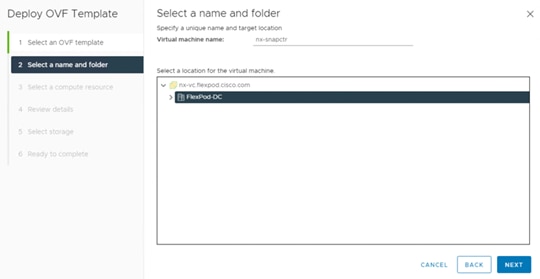
5. On the Select a compute resource page, choose a resource where you want to run the deployed VM template, and click NEXT.
6. On the Review details page, verify the OVA template details and click NEXT.
7. On the License agreements page, check the box I accept all license agreements.
8. On the Select storage page, change the datastore virtual disk format to Thin Provision and click NEXT.
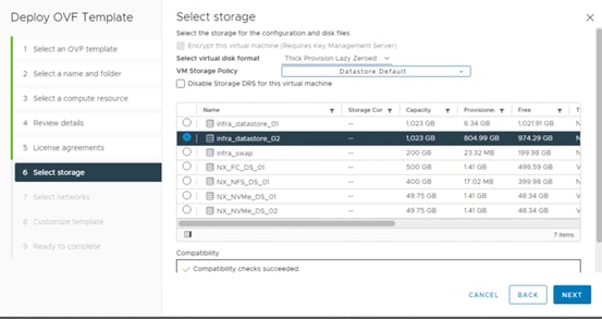
9. On the Select networks page, choose a source network, and map it to a destination network, and then click NEXT.
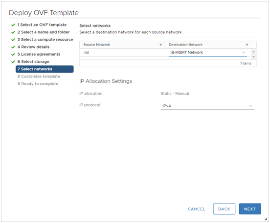
10. On the Customize template page, do the following:
a. In Register to existing vCenter, enter the vCenter credentials.
11. In Create SnapCenter Plug-in for VMware vSphere credentials, enter the SnapCenter Plug-in for VMware vSphere credentials.
12. In Create SCV credentials, create a username and password for the SCV maintenance user.
13. In Setup Network Properties, enter the network information.
14. In Setup Date and Time, choose the time zone where the vCenter is located.
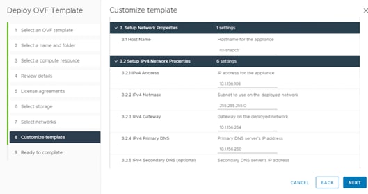
15. On the Ready to complete page, review the page and click FINISH.
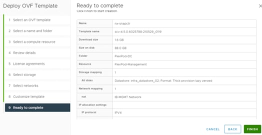
16. Navigate to the VM where the virtual appliance was deployed, then click the Summary tab, and then check the box for Power On to start the virtual appliance.
17. While the virtual appliance is powering on, click Install VMware tools in the orange banner displayed in the summary tab of the appliance.
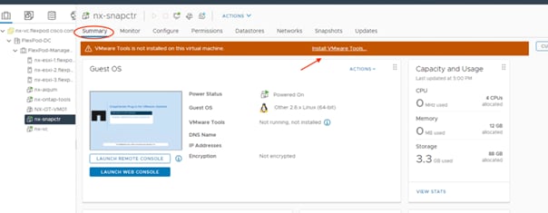
18. Log into SnapCenter Plug-in for VMware vSphere using the IP address (https://<ip>:8080 ) displayed on the appliance console screen with the credentials that you provided in the deployment wizard. Verify on the Dashboard that the virtual appliance is successfully connected to vCenter and the SnapCenter Plug-in for VMware vSphere is successfully enabled and connected.
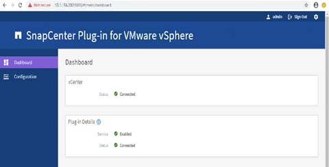
SnapCenter Plug-In for VMware vSphere in vCenter Server
After you have successfully installed the Plug-in for VMware vSphere, to configure SnapCenter and make it ready to backup virtual machines, follow these steps:
1. In your browser, navigate to VMware vSphere Web Client URL https://<vCenter Server>/ui.
![]() If currently logged into vCenter, logoff, close the open tab and sign-on again to access the SnapCenter Plug-in for VMware vSphere.
If currently logged into vCenter, logoff, close the open tab and sign-on again to access the SnapCenter Plug-in for VMware vSphere.
2. After logging on to the vSphere Web Client you will see a blue banner indicating the SnapCenter plug-in was successfully deployed. Click Refresh to activate the plug-in.
3. On the VMware vSphere Web Client page, click the menu and click SnapCenter Plug-in for VMware vSphere to launch the SnapCenter Plug-in for VMware GUI.
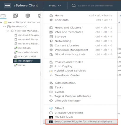
To add storage systems, follow these steps:
1. Go to the Storage Systems tab.
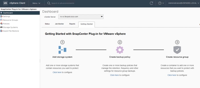
2. Click Add Storage System to add a cluster or SVM.
3. Enter vCenter, Storage System, user credentials, and other required information in following dialog box.
4. Check the box for Log SnapCenter server events to syslog and Send AutoSupport Notification for failed operation to storage system.
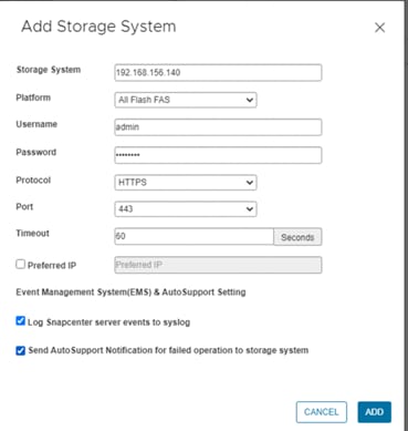
Create Backup Policies for Virtual Machines and Datastores
To create backup policies for VMs and datastores, follow these steps:
1. In the left Navigator pane of the VMware vSphere Web Client, click Policies.
2. On the Policies page, click New Policy in the toolbar.
3. On the New Backup Policy page, follow these steps:
a. Enter the policy name and a description.
b. Enter the backups to keep.
4. From the Frequency drop-down list, choose the backup frequency (hourly, daily, weekly, monthly, and on-demand only).
5. Expand the Advanced options and select VM Consistency and Include datastore with independent disks.
6. Click Add.
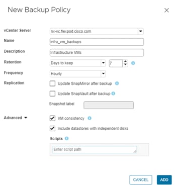
7. Create multiple policies as required for different sets of VMs or datastores.
Resource groups are groups of virtual machines or datastores that are backed up together. A backup policy is associated with the resource group to back up the virtual machines and retain a certain number of backups as defined in the policy.
To create resource groups, follow these steps:
1. In Navigator pane of the SnapCenter Plug-in for VMware vSphere, click Resource Groups and then click Create Resource Group. This is the easiest way to create a resource group. However, you can also create a resource group with one resource by performing one of the following steps:
● To create a resource group for one virtual machine, click VMs and Templates, right-click a virtual machine, choose NetApp SnapCenter from the drop-down list, and then choose Create Resource Group from the secondary drop-down list.
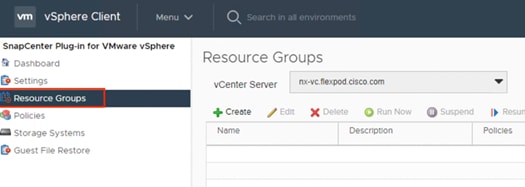
● To create a resource group for one datastore, click Storage, right-click a datastore, choose NetApp SnapCenter from the drop-down list, and then choose Create Resource Group from the secondary drop-down list.
2. In the General Info & Notification page, enter the resource group name and complete the notification settings. Click Next.
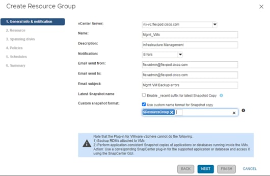
![]() Simplify the task of locating virtual machine and datastore snapshots by selecting the Custom snapshot format option and choose the desired label such as $ResourceGroup to have the resource group name appended to the snapshot name during snapshot operation.
Simplify the task of locating virtual machine and datastore snapshots by selecting the Custom snapshot format option and choose the desired label such as $ResourceGroup to have the resource group name appended to the snapshot name during snapshot operation.
3. Choose a datastore as the parent entity to create a resource group of virtual machines, and then choose the virtual machines from the available list. Click Next.
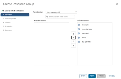
![]() Entire datastores can be backed up by selecting FlexPod-DC in the parent entity list box and selecting the datastore.
Entire datastores can be backed up by selecting FlexPod-DC in the parent entity list box and selecting the datastore.
4. From the Spanning Disks options, choose the Always include all spanning datastores option.
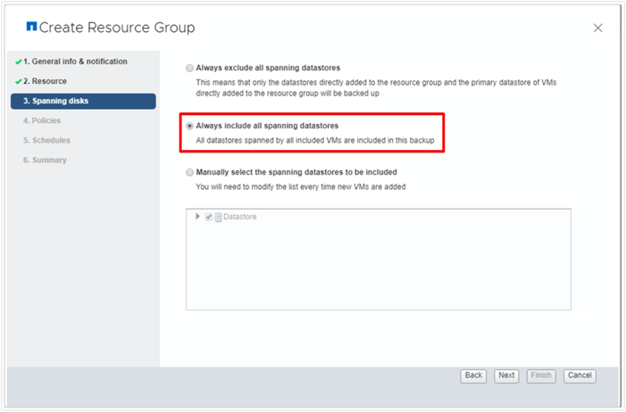
5. From the Policies tab, choose one of the previously created policies that you want to associate with the resource group and click Next.
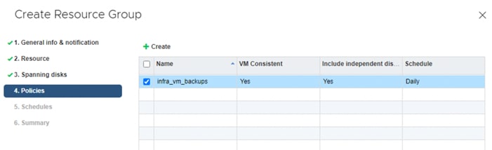
6. From the Schedules option, choose the schedule for each selected policy and click Next.
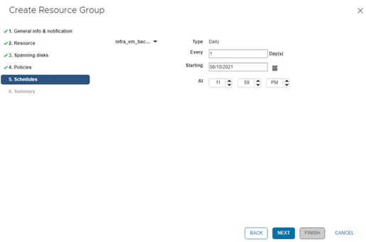
7. Review the summary and click Finish to complete the creation of the resource group.
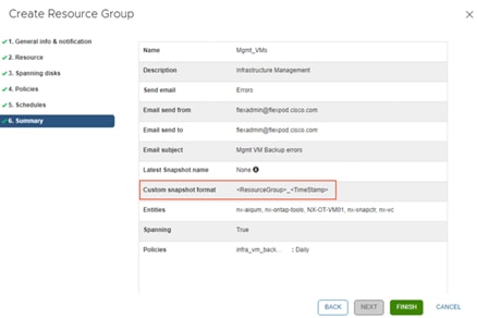
View Virtual Machine Backups from vCenter by Using SnapCenter Plug-In
Backups of the virtual machines included in the resource group occurs according to the schedule of the policies associated with the resource group. To view the backups associated with each schedule, follow these steps:
1. Navigate to the VMs and Templates tab.
2. Go to any virtual machine that is a member of a Resource Group, select the Configure tab. Under SnapCenter Plug-in for VMware vSphere choose the Backups tab to view all the backups available for the virtual machine..
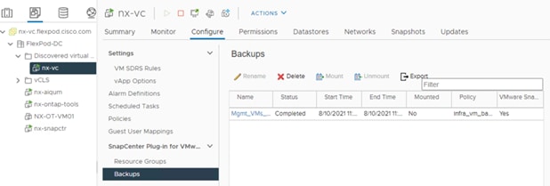
3. Navigate to the SnapCenter Plug-in for VMware vSphere and choose the Dashboard tab to view recent job activity, backup jobs and configuration details.
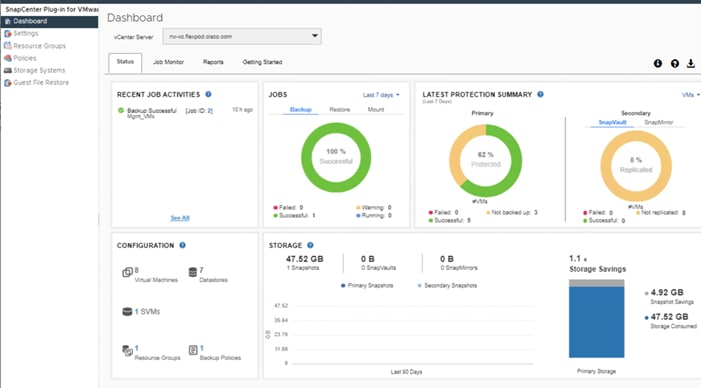
4. In the SnapCenter Plug-in for VMware vSphere, click Resource Groups and choose any resource group. In the right pane, the completed backups are displayed.
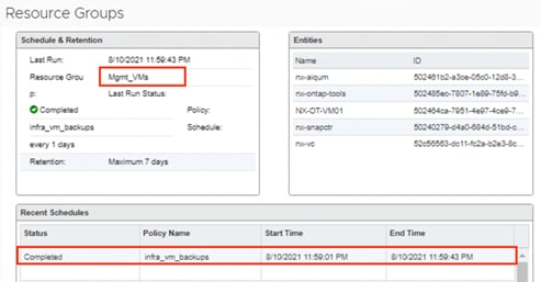
To create an on-demand backup for any resource group, follow these steps:
1. From the VMs and Templates tab, choose a virtual machine contained in the resource group where you want to create an on-demand backup.
2. Click the Configure > SnapCenter Plugin for VMware vSphere > Resource Groups.
3. Select the resource group and click Run Now to run the backup immediately.
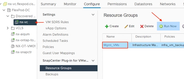
Restore from vCenter by Using SnapCenter Plug-In
To restore from vCenter by using SnapCenter Plug-in, follow these steps:
![]() The Plug-in for VMware vSphere provides native backup, recovery, and cloning of virtualized applications.
The Plug-in for VMware vSphere provides native backup, recovery, and cloning of virtualized applications.
1. Navigate to VMs and Templates, choose a VM and right-click to access the context menu. Choose NetApp SnapCenter > Restore.
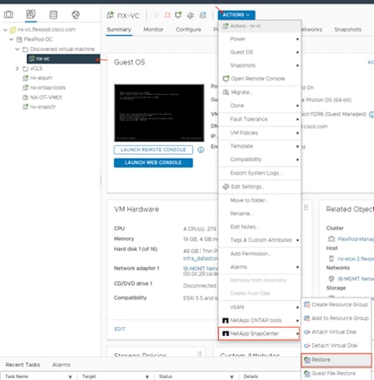
2. Choose a backup from which to restore. Click Next.
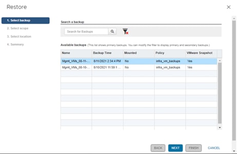
3. From the Restore Scope drop-down list:
a. Choose either "Entire virtual machine" to restore the virtual machine with all Virtual Machine Disks (VMDKs) or choose "Particular Virtual Disk" to restore the VMDK without affecting the virtual machine configuration and other VMDKs.
b. Choose the ESXi host that the VM should be restored to and check the box if you wish to restart the VM upon being restored. Click Next.
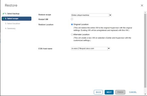
4. Choose the destination datastore and click Next.
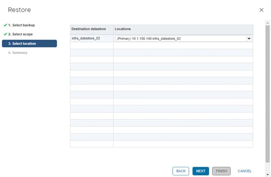
5. Review the Summary and click Finish to complete the restore process.
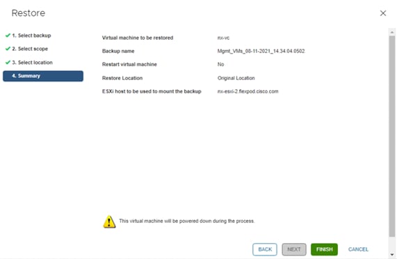
Active IQ Unified Manager 9.10
Active IQ Unified Manager enables you to monitor and manage the health and performance of your ONTAP storage systems and virtual infrastructure from a single interface. Unified Manager provides a graphical interface that displays the capacity, availability, protection, and performance status of the monitored storage systems.
This section describes the steps to deploy NetApp Active IQ Unified Manager 9.10 as a virtual appliance. The following table lists the recommended configuration for the virtual machine to install and run Active IQ Unified Manager to ensure acceptable performance.
Table 11. Virtual Machine Configuration
| Hardware Configuration |
Recommended Settings |
| RAM |
12 GB |
| Processors |
4 CPUs/ vCPUs |
| CPU Cycle Capacity |
9572 MHz total |
| Free Disk Space/virtual disk size |
5 GB - Thin provisioned 152 GB – Thick provisioned |
![]() There is a limit to the number of nodes that a single instance of Active IQ Unified Manager can monitor before you need to install a second instance of Active IQ Unified Manager. See the Unified Manager Best Practices Guide (TR-4621) for more details.
There is a limit to the number of nodes that a single instance of Active IQ Unified Manager can monitor before you need to install a second instance of Active IQ Unified Manager. See the Unified Manager Best Practices Guide (TR-4621) for more details.
Install NetApp Active IQ Unified Manager 9.10
Install Active IQ Unified Manager using Ansible
To install Active IQ Unified Manager using Ansible, follow these steps:
1. Follow the Pre-Requisites from https://github.com/NetApp-Automation/NetApp-AIQUM
2. Download ansible git: git clone https://github.com/NetApp-Automation/NetApp-AIQUM.git
3. To invoke the ansible scripts use the following command:
ansible-playbook aiqum.yml -t aiqum_setup
To install Active IQ Unified Manager 9.10 manually, follow these steps:
1. Download NetApp Active IQ Unified Manager for VMware vSphere OVA file from NetApp support site.
2. From the VMware vCenter, click the VMs and Templates tab, then click Actions> Deploy OVF Template.
3. Specify the location of the OVF Template and click NEXT.
4. On the Select a name and folder page, enter a unique name for the VM, and choose a deployment location, and then click NEXT.
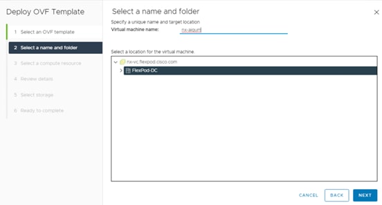
5. On the Select a compute resource page, choose a resource where you want to run the deployed VM template, and click NEXT.
6. On the Review details page, verify the OVA template details and click NEXT.
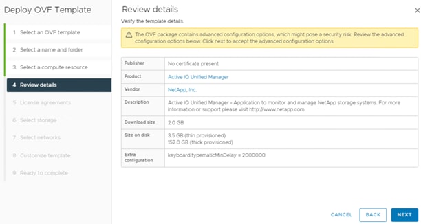
7. On the License agreements page, check the box for I accept all license agreements.
8. On the Select storage page, define where and how to store the files for the deployed OVF template:
a. Choose the disk format for the VMDKs.
b. Choose a VM Storage Policy.
c. Choose a datastore to store the deployed OVA template.
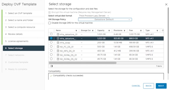
9. On the Select networks page, select a source network, and map it to a destination network, and then click NEXT.
10. On the Customize template page, provide network details.
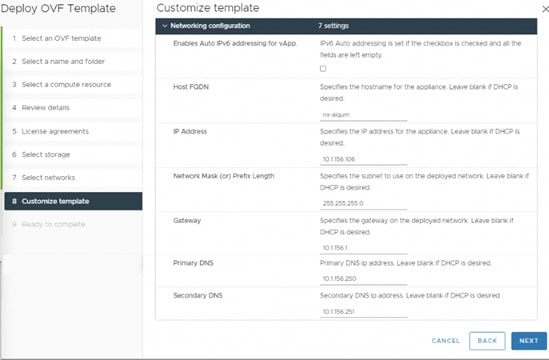
![]() Scroll through the customization template to ensure all required values are entered.
Scroll through the customization template to ensure all required values are entered.
11. On the Ready to complete page, review the page and click FINISH.
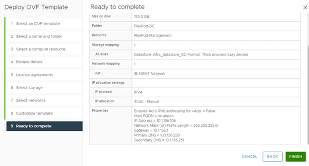
12. Choose the newly created Active IQ Unified Manager VM, right-click it and choose Power > Power On to start the virtual machine.
13. While the virtual machine is powering on, click the prompt in the yellow banner to Install VMware tools.
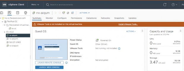
14. Open a console session to the Active IQ Unified Manager appliance and configure the time zone information when displayed.
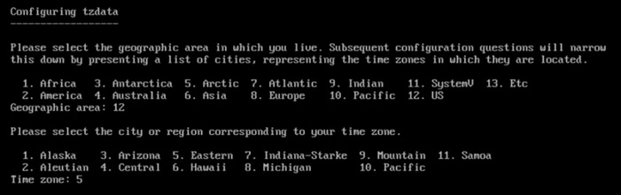
15. Create the maintenance user account when prompted by specifying a user account name and password.
![]() Store the maintenance user account and password in a secure location. It is required for the initial GUI login and to make any configuration changes to the appliance settings that may be needed in the future.
Store the maintenance user account and password in a secure location. It is required for the initial GUI login and to make any configuration changes to the appliance settings that may be needed in the future.
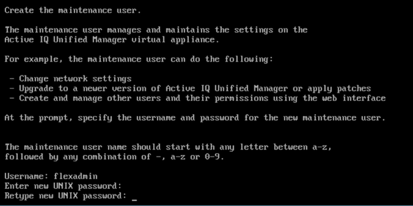
16. Log into NetApp Active IQ Unified Manager using the IP address or URL displayed on the deployment screen and the maintenance user credentials you created in the previous step.
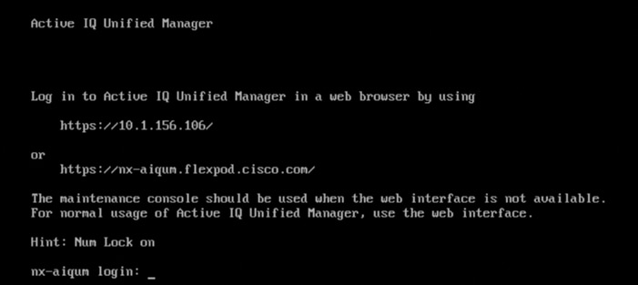
Configure Active IQ Unified Manager
To configure Active IQ Unified Manager and add a storage system for monitoring, follow these steps:
1. Launch a web browser and log into Active IQ Unified Manger.
2. Enter the email address that Unified Manager will use to send alerts, enter the mail server configuration, and the IP address or hostname of the NTP server. Choose Continue and complete the AutoSupport configuration.
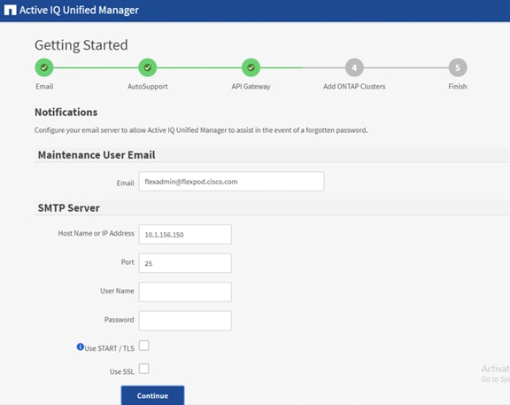
3. Configure AutoSupport for Unified Manager by clicking Agree and Continue.
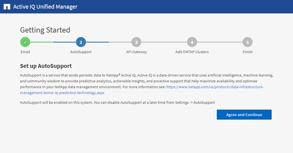
4. Check the box for Enable API Gateway and click Continue to setup the API gateway for Active IQ Unified Manager.
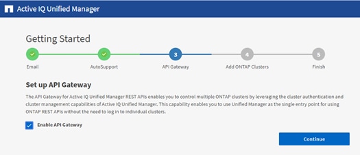
5. Enter the ONTAP cluster hostname or IP address and the admin login credentials then click Add.
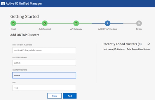
6. A security prompt will be displayed to authorize the cluster certificate. Choose Yes to trust the certificate.
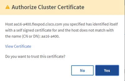
7. When prompted to trust the self-signed certificate from Active IQ Unified Manager, click Yes to finish and add the storage system.
![]() The initial discovery process can take up to 15 minutes to complete.
The initial discovery process can take up to 15 minutes to complete.
Add Local Users to Active IQ Unified Manager
To add a local user to Active IQ Unified Manager, follow these steps:
1. Navigate to the General section and click Users.
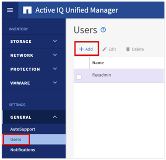
2. Click Add and complete the requested information:
a. Choose Local User for the Type.
b. Enter a username and password.
c. Add the user’s email address.
d. Choose the appropriate role for the new user.
3. Click Save to add the new user to Active IQ Unified Manager.
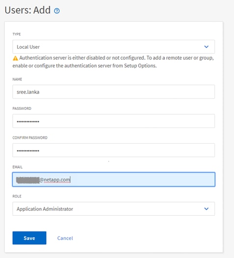
Configure Remote Authentication
Simplify user management and authentication for Active IQ Unified Manager by integrating it with Microsoft Active Directory. To connect Active IQ Unified Manager to Active Directory and perform user authentication with the Active Directory domain, follow these steps:
![]() You must be logged on as the maintenance user created during the installation or another user with Application Administrator privileges to configure remote authentication.
You must be logged on as the maintenance user created during the installation or another user with Application Administrator privileges to configure remote authentication.
1. Navigate to the General section and choose Remote Authentication.
2. Choose the option to Enable remote authentication and define a remote user or remote group.
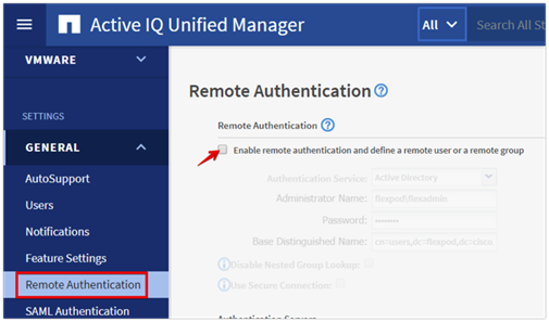
3. Choose Active Directory from the authentication service list.
4. Enter the Active Directory service account name and password. The account name can be in the format of domain\user or user@domain.
5. Enter the base DN where your Active Directory users reside.
6. If Active Directory LDAP communications are protected via SSL enable the Use Secure Connection option.
7. Add one or more Active Directory domain controllers by clicking Add and entering the IP or FQDN of the domain controller.
8. Click Save to enable the configuration.
![]() If you don’t know the base DN to your Active Directory user organizational unit, contact the Active Directory administrator at your organization to provide this information.
If you don’t know the base DN to your Active Directory user organizational unit, contact the Active Directory administrator at your organization to provide this information.
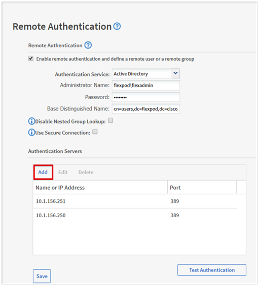
9. Click Test Authentication and enter an Active Directory username and password to test authentication with the Active Directory authentication servers.
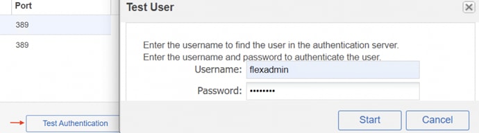
A result message displays indicating authentication was successful:
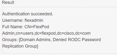
Add a Remote User to Active IQ Unified Manager
To add remote users that need to access Active IQ Unified Manager and authenticate with the Active Directory servers, follow these steps:
1. Navigate to the General section and choose Users.
2. Click Add and choose Remote User from the Type drop-down list.
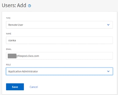
3. Enter the following information into the form:
a. The username of the Active Directory user.
b. Email address of the user.
c. Choose the appropriate role for the user
4. Click Save when finished to add the remote user to Active IQ Unified Manager.
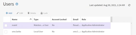
Add the vCenter Server to Active IQ Unified Manager
Active IQ Unified Manager provides visibility into vCenter and the virtual machines running inside the datastores backed by ONTAP storage. Virtual machines and storage are monitored to enable fast identification of performance issues within the various components of the virtual infrastructure stack.
Before adding vCenter into Active IQ Unified Manager, the log level of the vCenter server must be changed by following these steps:
1. In the vSphere client navigate to VMs and Templates and choose the vCenter instance from the top of the object tree.
2. Click the Configure tab, expand the settings, and choose General.
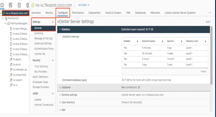
3. Click EDIT.
4. In the pop-up window under Statistics, locate the 5 minutes Interval Duration row and change the setting to Level 3 under the Statistics Level column. Click SAVE.
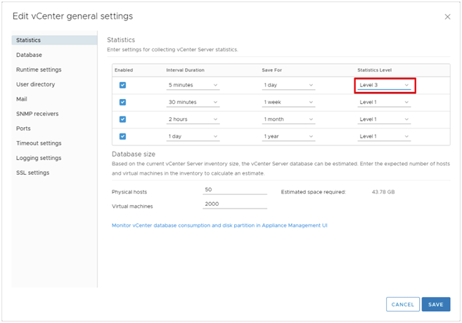
5. Return to Active IQ Unified Manager and navigate to the VMware section located under Inventory.
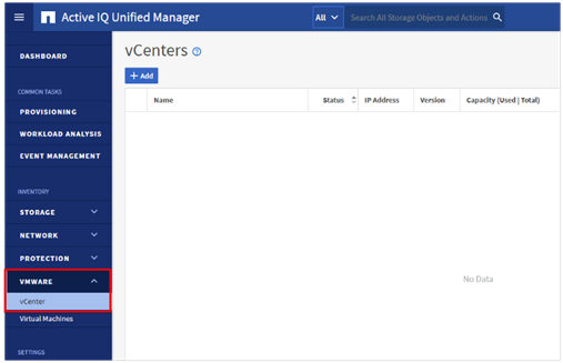
6. Expand the section and choose vCenter and click Add.
7. Enter the VMware vCenter server details and click Save.
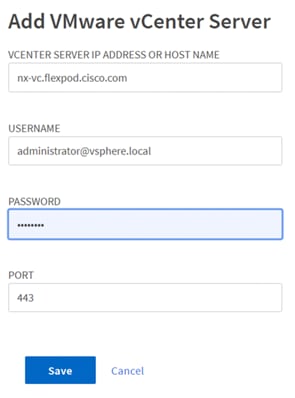
8. A dialog box will appear asking to authorize the certificate. Click Yes to accept the certificate and add the vCenter server.
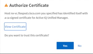
![]() It may take up to 15 minutes to discover the vCenter server. Performance data can take up to an hour after discovery to become available.
It may take up to 15 minutes to discover the vCenter server. Performance data can take up to an hour after discovery to become available.
View Virtual Machine Inventory
The virtual machine inventory is automatically added to Active IQ Unified Manager during discovery of the vCenter server. Virtual machines can be viewed in a hierarchical display detailing storage capacity, IOPS and latency for each component in the virtual infrastructure to troubleshoot the source of any performance related issues.
To review the virtual machine topology and statics, follow these steps:
1. Navigate to the VMware section located under Inventory, expand the section, and click Virtual Machines.
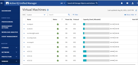
2. Choose a VM and click the blue caret to expose the topology view. Review the compute, network, and storage components and their associated IOPS and latency statistics.
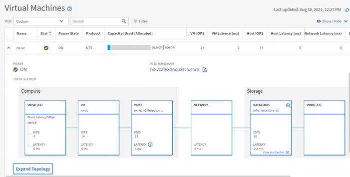
3. Click Expand Topology to see the entire hierarchy of the virtual machine and its virtual disks as it is connected through the virtual infrastructure stack. The VM components are mapped from vSphere and compute through the network to the storage.
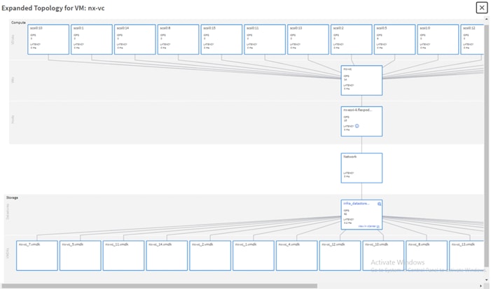
Review Security Compliance with Active IQ Unified Manager
Active IQ Unified Manager identifies issues and makes recommendations to improve the security posture of ONTAP. Active IQ Unified Manager evaluates ONTAP storage based on recommendations made in the Security Hardening Guide for ONTAP 9. Items are identified according to their level of compliance with the recommendations. All events identified do not inherently apply to all environments, for example, FIPS compliance. Review the Security Hardening Guide for NetApp ONTAP 9 (TR-4569) for additional information and recommendations for securing ONTAP 9.
![]()
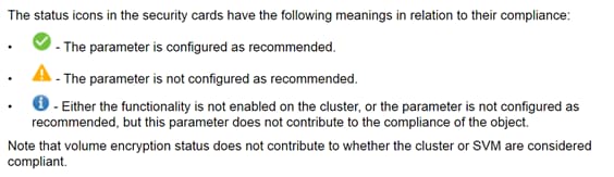
To identify security events in Active IQ Unified Manager, follow these steps:
1. Navigate to the URL of the Active IQ Unified Manager installation and login.
2. Choose the Dashboard from the left menu bar in Active IQ Unified Manager.
3. Locate the Security card and note the compliance level of the cluster and SVM. Click the blue arrow to expand the findings.
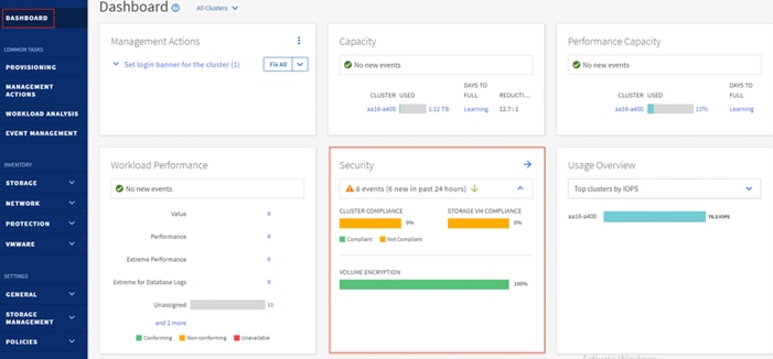
4. Locate Individual Cluster section and the Cluster Compliance card. From the drop-down list choose View All.
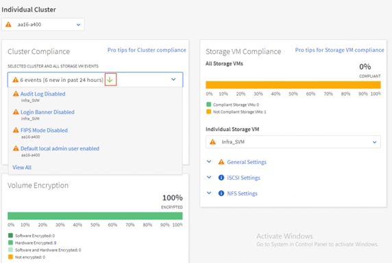
5. Choose an event from the list and click the name of the event to view the remediation steps.
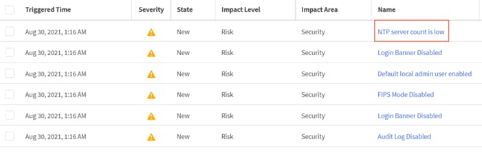
6. Remediate the risk if desired and perform the suggested actions to fix the issue.
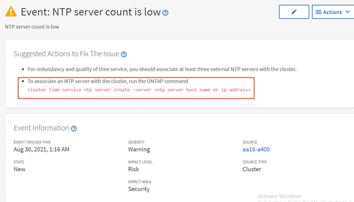
Remediate Security Compliance Findings
Active IQ identifies several security compliance risks after installation that can be immediately corrected to improve the security posture of ONTAP.
Correct Cluster Risks
To correct cluster risks, follow these steps:
1. To associate an NTP server with the cluster, run the ONTAP command:
cluster time-service ntp server create -server <ntp server host name or ip address>
2. Enable the login banner on the cluster:
security login banner modify -vserver <clustername> -message "Access restricted to authorized users"
NetApp Active IQ
NetApp Active IQ is a data-driven service that leverages artificial intelligence and machine learning to provide analytics and actionable intelligence for ONTAP storage systems. Active IQ uses AutoSupport data to deliver proactive guidance and best practices recommendations to optimize storage performance and minimize risk.
Additional Active IQ documentation is available on the Active IQ Documentation Resources web page.
Active IQ is automatically enabled when you configure AutoSupport on the ONTAP storage controllers. To get started with Active IQ, follow these steps:
1. Obtain the controller serial numbers from your ONTAP system with the following command:
system node show -fields serialnumber
2. Navigate to the Active IQ portal at https://activeiq.netapp.com/
3. Login with you NetApp support account ID
4. At the welcome screen enter the cluster name or one of controller serial numbers in the search box. Active IQ will automatically begin searching for the cluster and display results below.
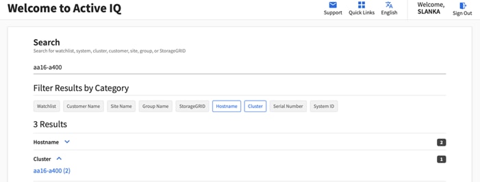
5. Choose the cluster name to launch the main dashboard.
6. From the drop-down list select Set Page as Default Landing View.
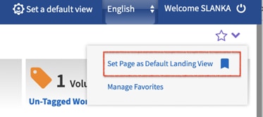
Add a Watchlist to the Discovery Dashboard
The system level dashboard is the default view for systems in Active IQ. To create a watchlist for the quick access cluster to cluster health and risk information, follow these steps:
1. Click Discovery Dashboard in the toolbar at the top of the Active IQ screen.
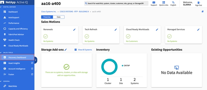
2. Click Create Watchlist and enter a name for the watchlist.
3. Choose the radio button to add systems by serial number and enter the cluster serial numbers to the watchlist.
4. Check the box for Make this my default watchlist if desired and click Create Watchlist.
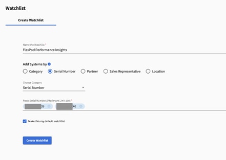
5. Click Manage watchlists and then click the ellipsis on the cluster watchlist card you created and click View in Discovery Dashboard.
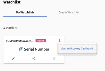
6. View the health and risk overview for the cluster.
Create Active IQ Digital Advisor Dashboard
The Active IQ Digital advisor provides a summary dashboard and system wellness score based on the health and risks that Active IQ have identified. The dashboard provides a quick way to identify and get proactive recommendations on how to mitigate risks in the storage environment including links to technical reports and mitigation plans.
To create an Active IQ Digital Advisor dashboard, follow these steps:
1. At the cluster dashboard, click Active IQ Digital Advisor from the top menu.
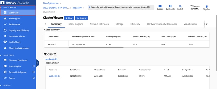
2. Choose the watchlist created in the previous step and click Next.
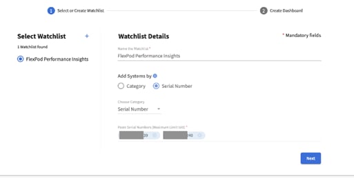
3. Accept the dashboard default name and choose all the available widgets.
4. Check the box Make this the default dashboard and click Create.
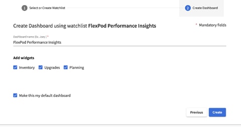
5. Review the enhanced dashboard including the Wellness Score and any recommended actions or risks.
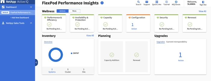
6. Switch between the Actions and Risks tabs to view the risks broken down by category or a list of all risks with their impact and links to corrective actions.
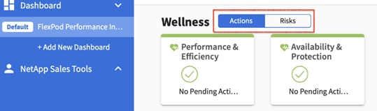
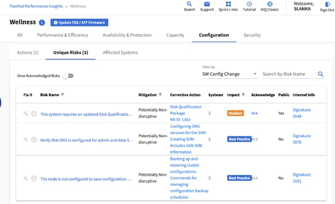
7. Click the link in the Corrective Action column to read the bug information or knowledge base article about how to remediate the risk.
![]() Additional tutorials and video walk-throughs of Active IQ features can be viewed on the Active IQ documentation web page.
Additional tutorials and video walk-throughs of Active IQ features can be viewed on the Active IQ documentation web page.
Cisco Intersight™ is a management platform delivered as a service with embedded analytics for your Cisco and third-party IT infrastructure. This platform offers an intelligent level of management that enables IT organizations to analyze, simplify, and automate their environments in more advanced ways than the prior generations of tools. Cisco Intersight provides an integrated and intuitive management experience for resources in the traditional data center and at the edge. With flexible deployment options to address complex security needs, getting started with Intersight is quick and easy.
Cisco Intersight offers flexible deployment either as Software as a Service (SaaS) on Intersight.com or running on your premises as Cisco Intersight Virtual Appliance. The virtual appliance provides the benefits of Cisco Intersight while allowing more flexibility for those with additional data locality and security requirements. The remainder of this section details Intersight deployment as SaaS on Intersight.com. To learn more about the virtual appliance, see the Cisco Intersight Virtual Appliance Getting Started Guide.
To configure Cisco Intersight, follow these steps:
1. If you do not already have a Cisco Intersight account, to claim your Cisco UCS system into a new account on Cisco Intersight, connect to https://intersight.com. If you have an existing Intersight account, connect to https://intersight.com and sign in with your Cisco ID, select the appropriate account, and skip to step 6.
2. Click Create an account.
3. Sign in with your Cisco ID.
4. Read, scroll through, and accept the End User License Agreement and click Next.
5. Enter an Account Name and click Create.
6. Choose ADMIN > Targets. Click Claim Target. Select Cisco UCS Domain (UCSM Managed) and click Start. Fill in the Device ID and Claim Code and click Claim. The Device ID and Claim Code can be obtained by connecting to Cisco UCS Manager and selecting Admin > All > Device Connector. The Device ID and Claim Code are on the right.
7. To claim your Cisco UCS system into an existing Intersight account, log into the account at https://Intersight.com. Choose Administration > Devices. Click Claim a New Device. Under Direct Claim, fill in the Device ID and Claim Code and click Claim. The Device ID and Claim Code can be obtained by connecting to Cisco UCS Manager and selecting Admin > All > Device Connector. The Device ID and Claim Code are on the right.
8. From the Cisco Intersight window, click ![]() and then click Licensing. If this is a new account, all servers connected to the UCS Domain will appear under the Base license Tier. If you have purchased Cisco Intersight licenses and have them in your Cisco Smart Account, click Register and follow the prompts to register this Cisco Intersight account to your Cisco Smart Account. Cisco Intersight also offers a one-time 90-day trial of Premier licensing for new accounts. Click Start Trial and then Start to begin this evaluation. The remainder of this section will assume Premier licensing.
and then click Licensing. If this is a new account, all servers connected to the UCS Domain will appear under the Base license Tier. If you have purchased Cisco Intersight licenses and have them in your Cisco Smart Account, click Register and follow the prompts to register this Cisco Intersight account to your Cisco Smart Account. Cisco Intersight also offers a one-time 90-day trial of Premier licensing for new accounts. Click Start Trial and then Start to begin this evaluation. The remainder of this section will assume Premier licensing.
9. From the Licensing Window, click Set Default Tier. From the drop-down list choose Premier for Tier and click Set.
10. Click Refresh to refresh the Intersight window with Premier, Advantage, and Essentials features added.
11. Click ![]() in the Intersight window and click Guided Help > Site Tour. Follow the prompts for a tour of Cisco Intersight.
in the Intersight window and click Guided Help > Site Tour. Follow the prompts for a tour of Cisco Intersight.
12. The Essentials tier of Cisco Intersight includes a Cisco driver check against the Cisco Hardware Compatibility List (HCL). In the Servers list, choose one of the servers in your VMware FlexPod-Management cluster by clicking the server name. Review the detailed General and Inventory information for the server. Click the HCL tab. Review the server information, the version of VMware ESXi, and the Cisco VIC driver versions.
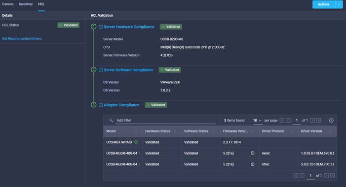
13. Using the Intersight Assist personality of the Cisco Intersight Virtual Appliance, VMware vCenter and NetApp Storage can be monitored (Advantage Licensing Tier) and configured (Premier Licensing Tier). To install Intersight Assist from an Open Virtual Appliance (OVA) in your VMware FlexPod-Management Cluster, first download the latest release of the Cisco Intersight Virtual Appliance for vSphere OVA from https://software.cisco.com/download/home/286319499/type/286323047/release/1.0.9-230?catid=268439477.
Refer to https://www.cisco.com/c/en/us/td/docs/unified_computing/Intersight/b_Cisco_Intersight_Appliance_Getting_Started_Guide/b_Cisco_Intersight_Appliance_Install_and_Upgrade_Guide_chapter_00.html and set up the DNS entries for the Intersight Assist hostname as specified under Before you begin.
14. From Hosts and Clusters in the VMware vCenter HTML5 client, right-click the FlexPod-Management cluster and click Deploy OVF Template.
15. Specify a URL or either browse to the intersight-appliance-installer-vsphere-1.0.9-230.ova or latest release file. Click NEXT.
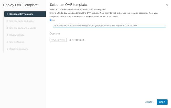
16. Name the Intersight Assist VM and choose the location. Click NEXT.
17. Choose the FlexPod-Management cluster and click NEXT.
18. Review details, click Ignore, and click NEXT.
19. Choose a deployment configuration (Tiny for just Intersight Assist, Small for Intersight Assist and IWO) and click NEXT.
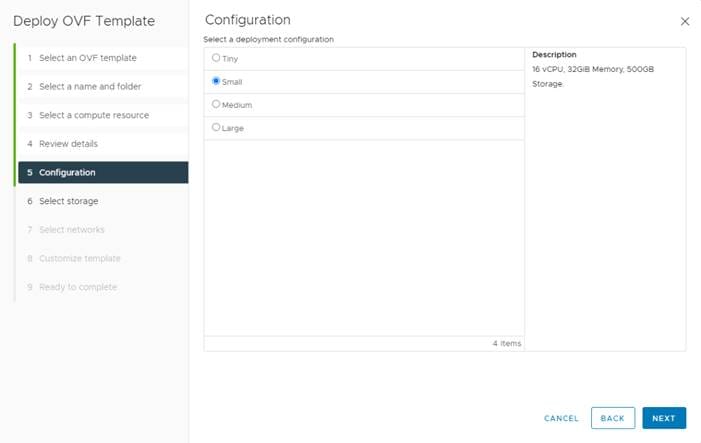
20. Choose infra_datastore_02 for storage and choose the Thin Provision virtual disk format. Click NEXT.
21. Choose IB-MGMT Network for the VM Network. Click NEXT.
22. Fill in all values to customize the template. Click NEXT.
23. Review the deployment information and click FINISH to deploy the appliance.
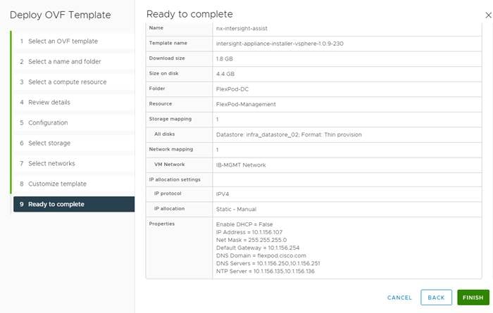
24. Once the OVA deployment is complete, right-click the Intersight Assist VM and click Edit Settings.
25. Expand CPU and adjust the Cores per Socket so that the number of Sockets matches your server CPU configuration. In this example 2 Sockets are shown. Click OK.
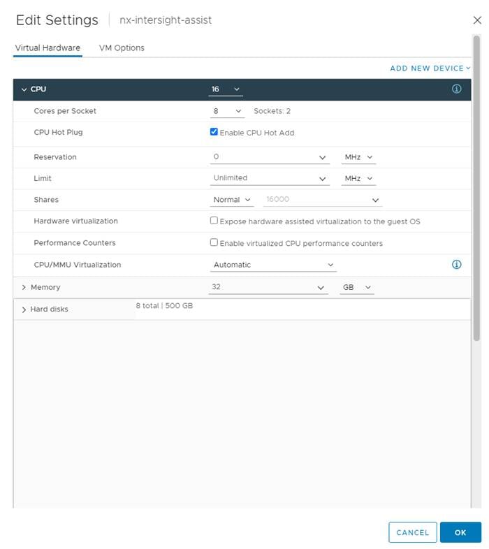
26. Right-click the Intersight Assist VM and choose Open Remote Console.
27. Click ![]() to power on the VM.
to power on the VM.
28. When you see the login prompt, close the Remote Console and connect to https://intersight-assist-fqdn.
![]() It may take a few minutes for https://intersight-assist-fqdn to respond.
It may take a few minutes for https://intersight-assist-fqdn to respond.
29. Navigate the security prompts and select Intersight Assist. Click Proceed.
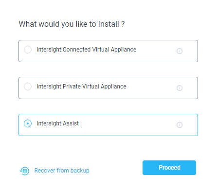
30. From Cisco Intersight, click ADMIN > Targets. Click Claim Target. Select Cisco Intersight Assist and click Start. Click OK on the warning. Copy and paste the Device ID and Claim Code shown in the Intersight Assist web interface to the Cisco Intersight Device Claim Direct Claim window. In Cisco Intersight, click Claim. Intersight Assist will now appear as a claimed device.
31. In the Intersight Assist web interface, verify that Intersight Assist is Connected Successfully, and click Continue.
![]() The Intersight Assist software will now be downloaded and installed into the Intersight Assist VM. This can take up to an hour to complete.
The Intersight Assist software will now be downloaded and installed into the Intersight Assist VM. This can take up to an hour to complete.
32. When the software download is complete, an Intersight Assist login screen will appear. Log into Intersight Assist with the admin user and the password supplied in the OVA installation. Check the Intersight Assist status and log out of Intersight Assist.
33. To claim the vCenter, from Cisco Intersight, click ADMIN > Targets. Click Claim Target. In the Select Target Type window, select VMware vCenter under Hypervisor and click Start. In the VMware vCenter window, make sure the Intersight Assist is correctly selected, fill in the vCenter information. If Intersight Workflow Optimizer (IWO) will be used, turn on Datastore Browsing Enabled and click Claim.
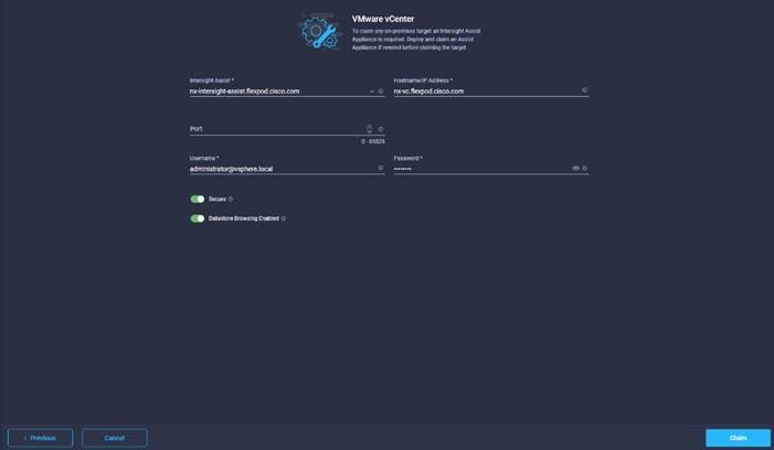
34. After a few minutes, the VMware vCenter will appear in the Devices list. It also can be viewed by clicking Intersight Assist in the Devices list.
35. Detailed information obtained from the vCenter can now be viewed by clicking Virtualization from the menu.
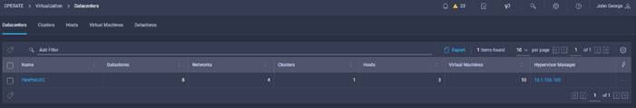
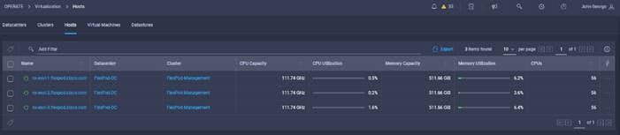
36. If Intersight Premier Licensing is enabled, VMware Virtualization tasks are also defined that can be used to create workflows under Orchestration.
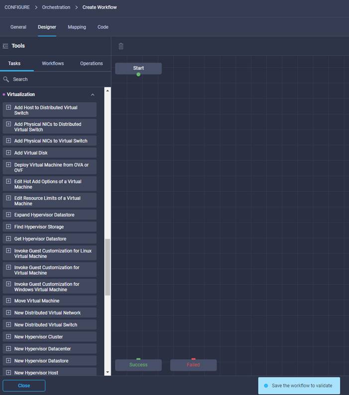
37. To claim the NetApp AIQ UM, from Cisco Intersight, click ADMIN > Targets. Click Claim a New Target. In the Select Target Type window, select NetApp Active IQ Unified Manager under Storage and click Start. In the VMware vCenter window, make sure the Intersight Assist is correctly selected, fill in the AIQ UM information, and click Claim.
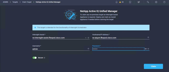
38. After a few minutes, the NetApp ONTAP Storage will appear in the Storage tab. The storage dashboard widgets can also be viewed from Monitoring tab.
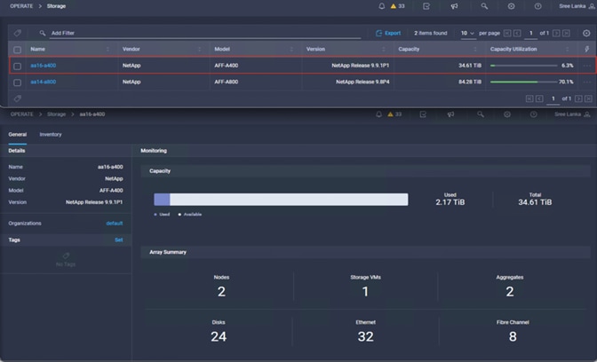
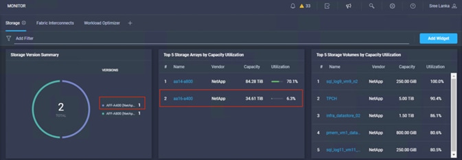
39. Storage and Virtualization tasks and workflows can now be executed from Cisco Intersight Orchestration tab.
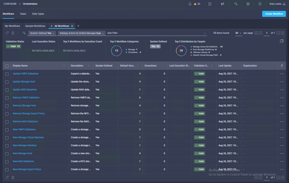
NetApp ONTAP Storage and Virtualization Workflows from Cisco Intersight
Sample Workflow: New NAS Datastore Workflow
This sample workflow creates an NFS storage volume and builds NAS datastores on the volume. It allows you to create an NAS or NFS storage volume by using NetApp storage tasks; then it uses the New NAS Datastore virtualization task to create the NFS datastore on the virtualization hypervisor.
Figure 4. Workflow Designer View
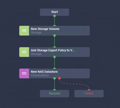
Table 12. Parameters and Values
| Parameter name |
Input value |
| Organization |
default |
| Workflow Instance Name |
New ONTAP NAS Datastore |
| Storage Device* |
aa16-a400 |
| Storage Vendor Virtual Machine* |
Infra_SVM |
| Aggregate* |
aa16_a400_01_NVME_SSD_1 |
| Export Policy* |
default |
| Volume* |
Infra_SVM_NFS_datastore_ICO_01 |
| Volume Capacity* |
100G |
| Mount path* |
/Infra_SVM_NFS_datastore_ICO_01 |
| Hypervisor Manager* |
nx-vc.flexpod.cisco.com |
| Datacenter* |
FlexPod-DC |
| Cluster |
FlexPod-Management |
| Datastore Name* |
Infra_SVM_NFS_datastore_ICO_01 |
| Datastore Type* |
NFS4.1 |
| Remote Host Names* |
192.168.50.141, 192.168.50.142 |
Sample Workflow: Update VMFS Datastore Workflow
Expand a datastore on hypervisor manager by extending the backing storage volume to specified capacity, and then grow the datastore to utilize the additional capacity. This workflow enables single click execution from Cisco Intersight to execute VMware hypervisor and NetApp ONTAP storage tasks and enable you to expand the VMFS or SAN datastore.
Figure 5. Workflow Designer View
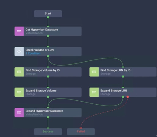
Table 13. Parameters and Values
| Parameter name |
Input value |
| Organization |
default |
| Workflow Instance Name |
Update ONTAP VMFS Datastore |
| Hypervisor Manager* |
nx-vc.flexpod.cisco.com |
| Datacenter* |
FlexPod-DC |
| Cluster |
FlexPod-Management |
| Datastore Name* |
Infra_SVM_VMFS_datastore_ICO_01 |
| Storage Device* |
aa16-a400 |
| Datastore Size |
220G |
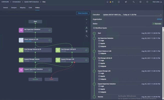
Validate the VMFS Datastore size from Cisco Intersight Virtualization tab.
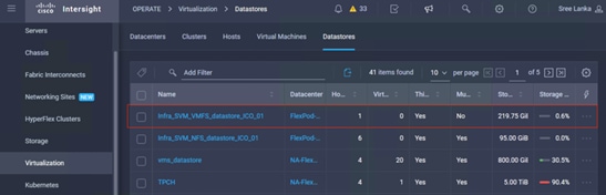
Custom Workflow: New FC Storage Virtual Machine and Add 4 FC LIFs
This workflow creates a new FC SVM and 4 new Fibre Channel interfaces. Using the NetApp ONTAP Storage tasks create a workflow to create a new SVM and add 4 new Logical Interface tasks for the Fiber Channel Protocol.
Figure 6. Workflow Designer View
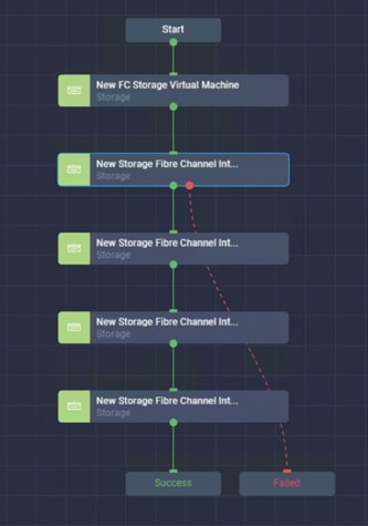
Table 14. Parameters and Values
| Parameter name |
Input value |
| Organization |
default |
| Display Name |
New FC SVM with 4 FC LIFS |
| Storage Device* |
aa16-a400 |
| Storage Vendor Virtual Machine* |
Data_SVM_ICO_01 |
| Storage Vendor Virtual Machine Options |
Storage VM Protocol: FCcol: FC |
| Interface Name |
Data_SVM_FC_LIF_ICO_01 |
| Interface options |
Data Protocol: FCP;Location Port:5a: Location Node Name: aa16-a400-01 |
| Interface Name |
Data_SVM_FC_LIF_ICO_02 |
| Interface options |
Data Protocol: FCP;Location Port:5b: Location Node Name: aa16-a400-01 |
| Interface Name |
Data_SVM_FC_LIF_ICO_03 |
| Interface options |
Data Protocol: FCP;Location Port:5a: Location Node Name: aa16-a400-02 |
| Interface Name |
Data_SVM_FC_LIF_ICO_04 |
| Interface options |
Data Protocol: FCP;Location Port:5b: Location Node Name: aa16-a400-02 |
Cisco Data Center Network Manager (DCNM)–SAN
Cisco DCNM-SAN can be used to monitor, configure, and analyze Cisco fibre channel fabrics. Cisco DCNM-SAN is deployed as a virtual appliance from an OVA and is managed through a web browser. SAN Analytics can be added to provide insights into your fabric by allowing you to monitor, analyze, identify, and troubleshoot performance issues.
Prerequisites
The following prerequisites need to be configured:
1. Licensing. Cisco DCNM-SAN includes a 60-day server-based trial license that can be used to monitor and configure Cisco MDS Fibre Channel switches and monitor Cisco Nexus switches. Both DCNM server-based and switch-based licenses can be purchased. Additionally, SAN Insights and SAN Analytics requires an additional switch-based license on each switch. Cisco MDS 32Gbps Fibre Channel switches provide a 120-day grace period to trial SAN Analytics.
![]() If using the Cisco Nexus 93180YC-FX for SAN switching, it does not support SAN Analytics.
If using the Cisco Nexus 93180YC-FX for SAN switching, it does not support SAN Analytics.
2. Passwords. Cisco DCNM-SAN passwords should adhere to the following password requirements:
● It must be at least eight characters long and contain at least one alphabet and one numeral.
● It can contain a combination of alphabets, numerals, and special characters.
● Do not use any of these special characters in the DCNM password for all platforms: <SPACE> " & $ % ' ^ = < > ; : ` \ | / , .*
3. DCNM SNMPv3 user on switches. Each switch (both Cisco MDS and Nexus) needs an SNMPv3 user added for DCNM to use to query and configure the switch. On each switch, enter the following command in configure terminal mode (in the example, the userid is snmpuser):
snmp-server user snmpadmin network-admin auth sha <password> priv aes-128 <privacy-password>
4. On Cisco MDS switches, type show run. If snmpadmin passphrase lifetime 0 is present, enter username snmpadmin passphrase lifetime 99999 warntime 14 gracetime 3.
![]() It is important to use auth type sha and privacy auth aes-128 for both the switch and UCS snmpadmin users.
It is important to use auth type sha and privacy auth aes-128 for both the switch and UCS snmpadmin users.
5. Type “copy run start” on all switches to save the running configuration to the startup configuration.
6. DCNM SNMPv3 user in UCSM. A SNMPv3 user needs to be added to UCSM to allow DCNM to query the LAN side of the fabric interconnects. In Cisco UCS Manager, click Admin. Navigate to All > Communication Management > Communication Services. Under SNMP, click Enabled, click Save Changes, and the click OK. Under SNMP Users, click Add. Enter the user name and enter and confirm the Password and Privacy Password.
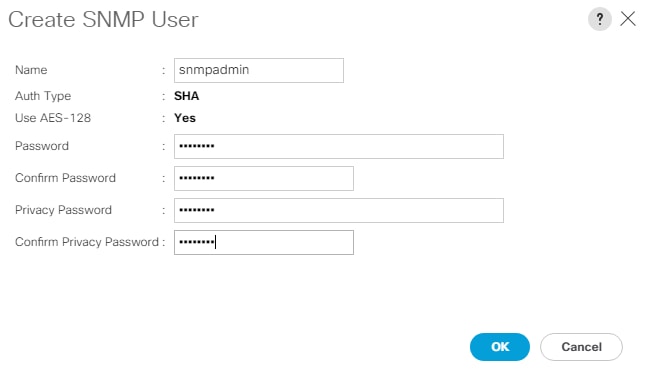
7. Click OK and then click OK again to complete adding the user.
Deploy the Cisco DCNM-SAN OVA
To deploy the Cisco DCNM-SAN OVA, follow these steps:
1. Download the Cisco DCNM 11.5.1 Open Virtual Appliance for VMware from https://software.cisco.com/download/home/281722751/type/282088134/release/11.5(1). Extract dcnm-va.11.5.1.ova from the ZIP file.
2. In the VMware vCenter HTML5 interface, click Menu > Hosts and Clusters.
3. Right-click the FlexPod-Management cluster and select Deploy OVF Template.
4. Choose Local file then click UPLOAD FILES. Navigate to choose dcnm-va.11.5.1.ova and click Open. Click NEXT.
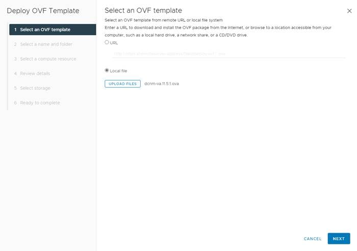
5. Name the virtual machine and choose the FlexPod-DC datacenter. Click NEXT.
6. Choose the FlexPod-Management cluster and click NEXT.
7. Review the details and click NEXT.
8. Scroll through and accept the license agreements. Click NEXT.
9. Choose the appropriate deployment configuration size and click NEXT.
![]() If using the SAN Insights and SAN Analytics feature, it is recommended to use the Huge size.
If using the SAN Insights and SAN Analytics feature, it is recommended to use the Huge size.
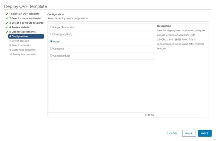
10. Choose infra_datastore_02 and the Thin Provision virtual disk format. Click NEXT.
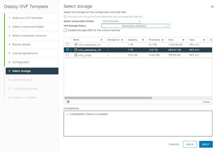
11. Choose IB-MGMT Network for the first and third Source Networks. Choose OOB-MGMT Network for the second enhanced-fabric-mgmt Source Network. Click NEXT.
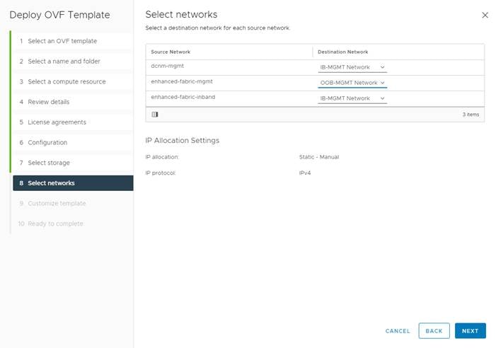
12. Fill in the management IP address, subnet mask, and gateway. Set the Extra Disk Size according to how many Cisco MDS switches you will be monitoring with this DCNM. If you are only monitoring the two Cisco MDS switches in this FlexPod deployment, set this field to 32. Click NEXT.
13. Review the settings and click FINISH to deploy the OVA.
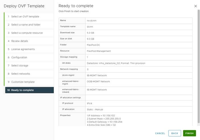
14. After deployment is complete, right-click the newly deployed DCNM VM and click Edit Settings. Expand CPU and adjust the Cores per Socket setting until the number of Sockets is set to match the number of CPUs in the UCS servers used in this deployment. The following example shows 2 sockets.
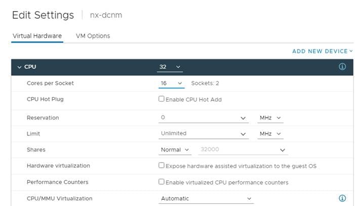
15. Click OK to complete the change.
16. Right-click the newly deployed DCNM VM and click Open Remote Console. Once the console is up, click ![]() to power on the VM. Once the VM has powered up, point a web browser to the URL displayed on the console.
to power on the VM. Once the VM has powered up, point a web browser to the URL displayed on the console.
17. Navigate the security prompts and click Get started.
18. Make sure Fresh installation – Standalone is selected and click Continue.
19. Choose SAN only for the Installation mode and leave Cisco Systems, Inc. for the OEM vendor and click Next.
20. Enter and repeat the administrator, database, and root passwords and click Next.
21. Enter the DCNM FQDN, a comma-separated list of DNS servers, a comma-separated list of NTP servers, and select the appropriate time zone. Click Next.
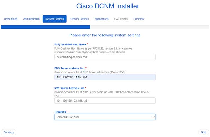
22. The Management Network settings should be filled in. For Out-of-Band Network, enter an IP address in the Out-of-Band management subnet. For the Out-of-Band Network, only input the IPV4 address with prefix. Do not put in the Gateway IPv4 Address. Do not enter any information for the In-Band Network. Scroll down and click Next.
23. If necessary, enter data for the Device connector configuration. Leave Internal Application Services Network set at the default setting and click Next.
24. Review the Summary details and click Start installation.
25. When the Installation status is complete, click Continue.
26. In the vCenter HTML5 client under Hosts and Clusters, choose the DCNM VM and click the Summary tab. If an alert is present that states “A newer version of VMware Tools is available for this virtual machine.”, click Upgrade VMware Tools. Choose Automatic Upgrade and click UPGRADE. Wait for the VMware Tools upgrade to complete.
Configure DCNM-SAN
To configure the DCNM-SAN, follow these steps:
1. When the DCNM installation is complete, the browser should redirect to the DCNM management URL.
2. Log in as admin with the password previously entered.
3. On the message that appears, choose Do not show this message again and click No.
4. If you have purchased DCNM server-based or switch-based licenses, follow the instructions that came with the licenses to install them. A new DCNM installation also has a 60-day trial license.
5. In the menu on the left, click Inventory > Discovery > LAN Switches.
6. Click ![]() to add LAN switches. In the Add LAN Devices window, enter the mgmt0 IP address of the Nexus switch A in the Seed Switch box. Enter the snmpadmin user name and password set up in the Prerequisites section above. Set Auth-Privacy to SHA_AES. Click Next.
to add LAN switches. In the Add LAN Devices window, enter the mgmt0 IP address of the Nexus switch A in the Seed Switch box. Enter the snmpadmin user name and password set up in the Prerequisites section above. Set Auth-Privacy to SHA_AES. Click Next.
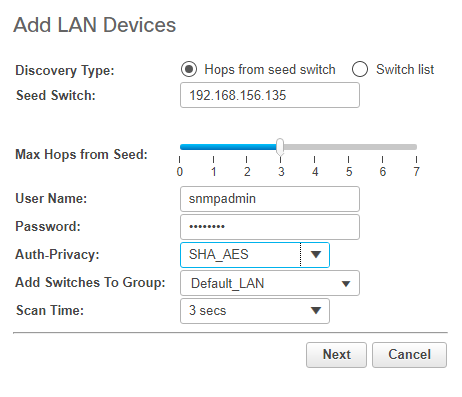
7. LAN switch discovery will take a few minutes. In the LAN Discovery list that appears, the two Nexus switches and two Fabric Interconnects that are part of this FlexPod should appear with a status of “manageable.” Using the checkboxes on the left, select the two Nexus switches and two Fabric Interconnects that are part of this FlexPod. Click Add.
8. After a few minutes (hit the Refresh icon in the upper right-hand corner), the two Nexus switches and two Fabric Interconnects that are part of this FlexPod will appear with detailed information.
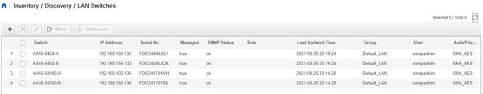
9. In the menu on the left, click Inventory > Discovery > SAN Switches.
10. Click ![]() to add a switching fabric.
to add a switching fabric.
11. Enter either the IP address or hostname of the first Cisco MDS 9132T switch. Leave Use SNMPv3/SSH selected. Set Auth-Privacy to SHA_AES. Enter the snmpadmin user name and password set up in the Prerequisites section above. Click Options>>. Enter the UCS admin user name and password. Click Add.
![]() If Cisco Nexus 93180YC-FX switches are being used for SAN switching, substitute them here for MDS 9132Ts. They will need to be added again under SAN switches since LAN and SAN switching are handled separately in DCNM.
If Cisco Nexus 93180YC-FX switches are being used for SAN switching, substitute them here for MDS 9132Ts. They will need to be added again under SAN switches since LAN and SAN switching are handled separately in DCNM.
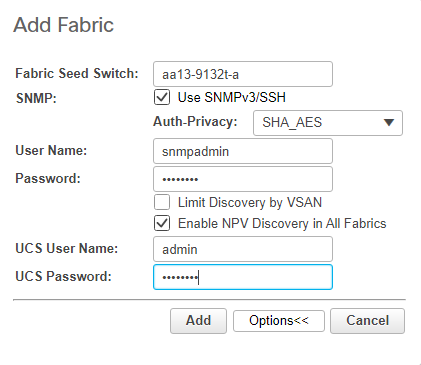
12. Repeat steps 9-11 to add the second Cisco MDS 9132T and Fabric Interconnect.
13. The two SAN fabrics should now appear in the Inventory.
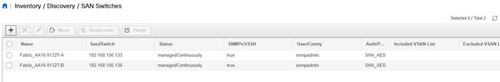
14. Choose Inventory > Discovery > Virtual Machine Manager.
15. Click ![]() to add the vCenter.
to add the vCenter.
16. In the Add VCenter window, enter the IP address of the vCenter VCSA. Enter the administrator@vsphere.local user name and password. Click Add. The vCenter should now appear in the inventory.
17. Choose Inventory > Switches. All LAN and SAN switches should now appear in the inventory.
18. Choose Administration > Performance Setup > LAN Collections.
19. Choose the Default_LAN group and all information you would like to collect. Click Apply. Click Yes to restart the Performance Collector.
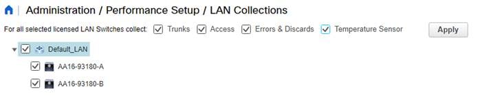
20. Choose Administration > Performance Setup > SAN Collections.
21. Choose both fabrics. Choose all information you would like to collect and click Apply. Click Yes to restart the Performance Collector.
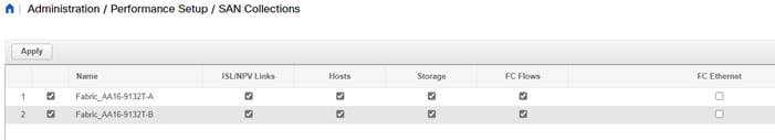
22. Choose Configure > SAN > Device Alias. Since device-alias mode enhanced was configured in the Cisco MDS 9132T switches, Device Aliases can be created and deleted from DCNM and pushed to the MDS switches.
23. Choose Configure > SAN > Zoning. Just as Device Aliases can be created and deleted from DCNM, zones can be created, deleted, and modified in DCNM and pushed to the MDS switches. Remember to enable Smart Zoning and to Zone by Device Alias.
You can now explore all of the different options and information provided by DCNM SAN. See Cisco DCNM SAN Management for OVA and ISO Deployments Configuration Guide, Release 11.5(1).
Configure SAN Insights in DCNM SAN
The SAN Insights feature enables you to configure, monitor, and view the flow analytics in fabrics. Cisco DCNM enables you to visually see health-related indicators in the interface so that you can quickly identify issues in fabrics. Also, the health indicators enable you to understand the problems in fabrics. The SAN Insights feature also provides more comprehensive end-to-end flow-based data from host to LUN.
● Ensure that the time configurations set above, including daylight savings settings are consistent across the MDS switches and Cisco DCNM.
● SAN Insights requires installation of a switch-based SAN Analytics license on each switch. To trial the feature, each switch includes a one-time 120-day grace period for SAN Analytics from the time the feature is first enabled.
● SAN Insights supports current Fibre Channel Protocol (SCSI) and NVMe over Fibre Channel (NVMe).
● SAN Insights works by enabling SAN Analytics and Telemetry Streaming on each switch. The switches then stream the SAN Analytics data to DCNM, which collects, correlates, and displays statistics. All configurations can be done from DCNM.
● Only Cisco MDS switches support SAN Analytics. Cisco Nexus 93180YC-FX switches do not support SAN Analytics.
● For more information on SAN Insights, see the SAN Insights sections of Cisco DCNM SAN Management for OVA and ISO Deployments Configuration Guide, Release 11.5(1).
● For more information on SAN Analytics, see https://www.cisco.com/c/en/us/td/docs/switches/datacenter/mds9000/sw/8_x/config/san_analytics/cisco-mds9000-san-analytics-telemetry-streaming-config-guide-8x.html.
To configure SAN Insights in DCNM SAN, follow these steps:
1. Click Configure > SAN > SAN Insights. Click Continue.
2. Choose Fabric A. Click Continue.
3. Choose the Fabric A Cisco MDS switch. Under Install Query click None and from the drop-down list click Storage. Under Subscriptions, choose SCSI & NVMe or whatever you have currently installed. Optionally, under Receiver, choose the IP address in the Out-of-Band Management subnet configured for DCNM. Click Save, then click Continue.
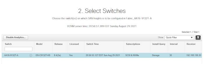
4. Review the information and click Continue.
5. Expand the switch and then the module. Under Enable / Disable SCSI Telemetry, click the left icon to enable telemetry on the ports connected to the NetApp AFF A400. Under Enable / Disable NVMe Telemetry, click the left icon to enable telemetry on the ports connected to the NetApp AFF A400. Click Continue.
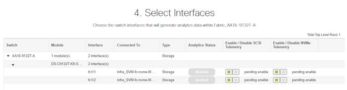
6. Review the information and click Commit to push the configuration to the Cisco MDS switch.
7. Ensure that the two operations were successful and click Close.
8. Repeat steps 1 - 7 to install SAN Analytics and Telemetry on the Fabric B switch.
9. After approximately two hours, you can view SAN Analytics data under the Dashboard and Monitor.
Provision a Sample Application Tenant
This section describes a sample procedure for provisioning an application tenant. The procedure refers to previous sections of this document and can be used as a guide and modified as needed when provisioning an application tenant. Follow these steps:
1. Plan your application tenant and determine what storage protocols will be provided in the tenant. In the architecture explained in this document, fibre channel, NFS, iSCSI, and CIFS/SMB (CIFS/SMB have not been discussed in this document) can be provided to the tenant. Also, plan what network VLANs the tenant will use. It is recommended to have a VLAN for virtual machine management traffic. One or two VLANs (iSCSI needs two if VMware RDM LUNs or iSCSI datastores will be provisioned) are also needed for each storage protocol used except fibre channel. If the infrastructure NFS VLAN will be used in the tenant, consider migrating the infrastructure NFS VMkernel port on each host to the vDS to take advantage of Ethernet adapter policy queuing. Fibre channel will have new storage LIFs defined with the same VSANs configured for the FlexPod Infrastructure.
2. In the Cisco Nexus switches, declare all added VLANs and configure the VM VLAN as an allowed VLAN on the Cisco UCS port channels and the vPC peer link. Also, Layer 3 with HSRP or VRRP can be configured in the Cisco Nexus switches to provide this VLAN access to the outside. Layer 3 setup is not explained in this document but is explained in the Nexus 9000 documentation. Configure the storage VLANs on the Cisco UCS and storage port channels, and on the vPC peer link. The VM VLAN can also be added to the storage port channels in order to configure the tenant SVM management interface on this VLAN.
3. In the storage cluster:
a. Create a broadcast domain with MTU 1500 for the tenant SVM management interface. Create a broadcast domain with MTU 9000 for each tenant storage protocol except fibre channel.
b. Create VLAN interface ports on the node interface group on each node for tenant SVM management (VM VLAN) and for the VLAN for each storage protocol except fibre channel. Add these VLAN ports to the appropriate broadcast domains.
c. Create the tenant SVM and follow all procedures in that section.
d. Create Load-Sharing Mirrors for the tenant SVM.
e. Create the FC or iSCSI service for the tenant SVM if fibre channel or iSCSI is being deployed in this tenant.
f. Optionally, create a self-signed security certificate for the tenant SVM.
g. Configure NFSv3 for the tenant SVM.
h. Create a VM datastore volume in the tenant SVM.
i. If fibre channel is being deployed in this tenant, configure four FCP LIFs in the tenant SVM on the same fibre channel ports as in the Infrastructure SVM.
j. If iSCSI is being deployed in this tenant, configure four iSCSI LIFs in the tenant SVM on the iSCSI VLAN interfaces.
k. Create an NFS LIF in the tenant SVM on each storage node.
l. Create a boot LUN in the esxi_boot volume in the Infra-SVM for each tenant VMware ESXi host.
m. Add the tenant SVM Administrator, SVM management LIF on the SVM management VLAN port, and default route for the SVM.
4. In Cisco UCS, one method of tenant setup is to dedicate a VMware ESXi cluster and set of UCS servers to each tenant. Service profiles will be generated for at least two tenant ESXi hosts. These hosts can boot from LUNs from the esxi_boot volume in the Infra-SVM but will also have access to FC storage in the tenant SVM.
5. Create a Server Pool for the tenant ESXi host servers.
6. Create all tenant VLANs in the LAN Cloud.
7. Add the tenant VLANs to the vDS vNIC templates.
8. Generate service profiles from the service profile template with the vMedia policy for the tenant ESXi hosts. Remember to bind these service profiles to the service profile template without the vMedia policy after VMware ESXi installation.
9. In the Cisco MDS 9132T switches:
a. Create device aliases for the tenant ESXi host vHBAs and the FC LIFs in the tenant storage SVM.
b. Add the tenant host initiators to the Infra-SVM zone.
10. Create a zone for the tenant SVM with fibre channel targets from the tenant SVM.
11. Add these zones to the Fabric zoneset and activate the zoneset.
12. In the storage cluster:
a. Create igroups for the tenant ESXi hosts in both the Infra-SVM and tenant SVM. Also, create an igroup in the tenant SVM that includes the WWPNs for all tenant ESXi hosts to support shared storage from the tenant SVM.
13. In Infra-SVM, map the boot LUNs created earlier to the tenant ESXi hosts. Tenant FC or iSCSI storage can be created later using NetApp VSC.
14. Install and configure VMware ESXi on all tenant host servers. It is not necessary to map infra_datastore unless you want the tenant ESXi hosts to have access to VMs or VM templates in these datastores.
15. In VMware vCenter, create a cluster for the tenant ESXi hosts. Add the hosts to the cluster.
16. Using the vCenter HTML5 Client, add the tenant hosts to vDS0 or create a tenant vDS and add the hosts to it. In vDS0, add port-profiles for the tenant VLANs. When migrating the hosts to the vDS, leave only the ESXi management interfaces on vSwitch0.
17. Back in vCenter, add in any necessary VMkernel ports for storage interfaces remembering to set the MTU correctly on these interfaces. Mount the tenant NFS datastore on the tenant cluster if one was created. Tenant iSCSI VMkernel ports can be created on the vDS with the port groups pinned to the appropriate fabric.
18. Using the NetApp VSC plugin to the vCenter HTML5 Client, set recommended values for all tenant ESXi hosts. Ensure the NetApp NFS Plug-in for VMware VAAI is installed on all tenant hosts and reboot each host.
19. You can now begin provisioning virtual machines on the tenant cluster. The NetApp VSC plugin can be used to provision fibre channel, iSCSI, and NFS datastores.
20. Optionally, use NetApp SnapCenter to provision backups of tenant virtual machines.
FlexPod with Cisco Nexus 93180YC-FX SAN Switching Configuration – Part 1
If the Cisco Nexus switches are to be used for both LAN and SAN switching in the FlexPod configuration, either an automated configuration with Ansible or a manual configuration can be done. For either configuration method, the following base switch setup must be done manually. Figure 7 shows the validation lab cabling for this setup.
Figure 7. FlexPod Cabling for Cisco Nexus 93180YC-FX SAN Switching
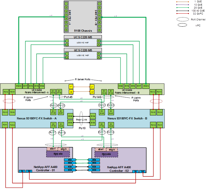
FlexPod Cisco Nexus 93180YC-FX SAN Switching Base Configuration
The following procedures describe how to configure the Cisco Nexus 93180YC-FX switches for use in a base FlexPod environment that uses the switches for both LAN and SAN switching. This procedure assumes you’re using Cisco Nexus 9000 9.3(7), the Cisco suggested Nexus switch release at the time of this validation.
Set Up Initial Configuration in Cisco Nexus 93180YC-FX A
To set up the initial configuration for the Cisco Nexus A switch on <nexus-A-hostname>, follow these steps:
1. Configure the switch:
![]() On initial boot and connection to the serial or console port of the switch, the NX-OS setup should automatically start and attempt to enter Power on Auto Provisioning.
On initial boot and connection to the serial or console port of the switch, the NX-OS setup should automatically start and attempt to enter Power on Auto Provisioning.
Abort Power On Auto Provisioning [yes - continue with normal setup, skip - bypass password and basic configuration, no - continue with Power On Auto Provisioning] (yes/skip/no)[no]: yes
Disabling POAP.......Disabling POAP
poap: Rolling back, please wait... (This may take 5-15 minutes)
---- System Admin Account Setup ----
Do you want to enforce secure password standard (yes/no) [y]: Enter
Enter the password for "admin": <password>
Confirm the password for "admin": <password>
Would you like to enter the basic configuration dialog (yes/no): yes
Create another login account (yes/no) [n]: Enter
Configure read-only SNMP community string (yes/no) [n]: Enter
Configure read-write SNMP community string (yes/no) [n]: Enter
Enter the switch name: <nexus-A-hostname>
Continue with Out-of-band (mgmt0) management configuration? (yes/no) [y]: Enter
Mgmt0 IPv4 address: <nexus-A-mgmt0-ip>
Mgmt0 IPv4 netmask: <nexus-A-mgmt0-netmask>
Configure the default gateway? (yes/no) [y]: Enter
IPv4 address of the default gateway: <nexus-A-mgmt0-gw>
Configure advanced IP options? (yes/no) [n]: Enter
Enable the telnet service? (yes/no) [n]: Enter
Enable the ssh service? (yes/no) [y]: Enter
Type of ssh key you would like to generate (dsa/rsa) [rsa]: Enter
Number of rsa key bits <1024-2048> [1024]: Enter
Configure the ntp server? (yes/no) [n]: Enter
Configure default interface layer (L3/L2) [L2]: Enter
Configure default switchport interface state (shut/noshut) [noshut]: shut
Enter basic FC configurations (yes/no) [n]: y
Configure default physical FC switchport interface state (shut/noshut) [shut]: Enter
Configure default switchport trunk mode (on/off/auto) [on]: auto
Configure default zone policy (permit/deny) [deny]: Enter
Enable full zoneset distribution? (yes/no) [n]: y
Configure CoPP system profile (strict/moderate/lenient/dense) [strict]: Enter
Would you like to edit the configuration? (yes/no) [n]: Enter
2. Review the configuration summary before enabling the configuration:
Use this configuration and save it? (yes/no) [y]: Enter
Set Up Initial Configuration in Cisco Nexus 93180YC-FX B
To set up the initial configuration for the Cisco Nexus B switch on <nexus-B-hostname>, follow these steps:
1. Configure the switch:
![]() On initial boot and connection to the serial or console port of the switch, the NX-OS setup should automatically start and attempt to enter Power on Auto Provisioning.
On initial boot and connection to the serial or console port of the switch, the NX-OS setup should automatically start and attempt to enter Power on Auto Provisioning.
Abort Power On Auto Provisioning [yes - continue with normal setup, skip - bypass password and basic configuration, no - continue with Power On Auto Provisioning] (yes/skip/no)[no]: yes
Disabling POAP.......Disabling POAP
poap: Rolling back, please wait... (This may take 5-15 minutes)
---- System Admin Account Setup ----
Do you want to enforce secure password standard (yes/no) [y]: Enter
Enter the password for "admin": <password>
Confirm the password for "admin": <password>
Would you like to enter the basic configuration dialog (yes/no): yes
Create another login account (yes/no) [n]: Enter
Configure read-only SNMP community string (yes/no) [n]: Enter
Configure read-write SNMP community string (yes/no) [n]: Enter
Enter the switch name: <nexus-B-hostname>
Continue with Out-of-band (mgmt0) management configuration? (yes/no) [y]: Enter
Mgmt0 IPv4 address: <nexus-B-mgmt0-ip>
Mgmt0 IPv4 netmask: <nexus-B-mgmt0-netmask>
Configure the default gateway? (yes/no) [y]: Enter
IPv4 address of the default gateway: <nexus-B-mgmt0-gw>
Configure advanced IP options? (yes/no) [n]: Enter
Enable the telnet service? (yes/no) [n]: Enter
Enable the ssh service? (yes/no) [y]: Enter
Type of ssh key you would like to generate (dsa/rsa) [rsa]: Enter
Number of rsa key bits <1024-2048> [1024]: Enter
Configure the ntp server? (yes/no) [n]: Enter
Configure default interface layer (L3/L2) [L2]: Enter
Configure default switchport interface state (shut/noshut) [noshut]: shut
Enter basic FC configurations (yes/no) [n]: y
Configure default physical FC switchport interface state (shut/noshut) [shut]: Enter
Configure default switchport trunk mode (on/off/auto) [on]: auto
Configure default zone policy (permit/deny) [deny]: Enter
Enable full zoneset distribution? (yes/no) [n]: y
Configure CoPP system profile (strict/moderate/lenient/dense) [strict]: Enter
Would you like to edit the configuration? (yes/no) [n]: Enter
2. Review the configuration summary before enabling the configuration:
Use this configuration and save it? (yes/no) [y]: Enter
![]() SAN switching requires both the SAN_ENTERPRISE_PKG and FC_PORT_ACTIVATION_PKG licenses. Ensure these licenses are installed on each Nexus 93180YC-FX switch.
SAN switching requires both the SAN_ENTERPRISE_PKG and FC_PORT_ACTIVATION_PKG licenses. Ensure these licenses are installed on each Nexus 93180YC-FX switch.
![]() This section is structured as a green field switch setup. If existing switches that are switching active traffic are being setup, execute this procedure down through Perform TCAM Carving and Configure Unified Ports in Cisco Nexus 93180YC-FX A and B first on one switch and then when that is completed, execute on the other switch.
This section is structured as a green field switch setup. If existing switches that are switching active traffic are being setup, execute this procedure down through Perform TCAM Carving and Configure Unified Ports in Cisco Nexus 93180YC-FX A and B first on one switch and then when that is completed, execute on the other switch.
Install feature-set fcoe in Cisco Nexus 93180YC-FX A and B
To add the fcoe feature-set, follow this step on both switches:
1. Run the following commands to set global configurations:
config t
install feature-set fcoe
feature-set fcoe
system default switchport trunk mode auto
system default switchport mode F
![]() These steps are provided in case the basic FC configurations were not configured in the switch setup script detailed in the previous section.
These steps are provided in case the basic FC configurations were not configured in the switch setup script detailed in the previous section.
Set System-Wide QoS Configurations in Cisco Nexus 93180YC-FX A and B
To set system-wide QoS configurations for FCoE for no-drop traffic support, follow this step on both switches:
1. Run the following commands to set global configurations:
config t
system qos
service-policy type queuing input default-fcoe-in-que-policy
service-policy type queuing output default-fcoe-8q-out-policy
service-policy type network-qos default-fcoe-8q-nq-policy
copy run start
Perform TCAM Carving and Configure Unified Ports in Cisco Nexus 93180YC-FX A and B
SAN switching requires TCAM carving for lossless fibre channel no-drop support. Also, unified ports need to be converted to fc ports. To perform TCAM carving on the Cisco Nexus switches and to convert ports 1-16 to fc, follow these steps:
1. Run the following commands:
hardware access-list tcam region ing-racl 1536
hardware access-list tcam region ing-ifacl 256
hardware access-list tcam region ing-redirect 256
slot 1
port 1-8 type fc
copy running-config startup-config
reload
This command will reboot the system. (y/n)? [n] y
2. After the switch reboots, log back in as admin. Run the following commands:
show hardware access-list tcam region |i i ing-racl
show hardware access-list tcam region |i i ifacl
show hardware access-list tcam region |i i ing-redirect
show int status
FlexPod Cisco Nexus 93180YC-FX SAN Switching Ethernet Switching Automated Configuration
For the automated configuration of the Ethernet part of the Cisco Nexus 93180YC-FX switches when using the switches for SAN switching, once the base configuration is set, return to Ansible Nexus Switch Configuration and execute from there.
FlexPod Cisco Nexus 93180YC-FX SAN Switching Ethernet Switching Manual Configuration
For the manual configuration of the Ethernet part of the Cisco Nexus 93180YC-FX switches when using the switches for SAN switching, once the base configuration above is set, return to FlexPod Cisco Nexus Switch Manual Configuration and execute from there.
FlexPod with Cisco Nexus 93180YC-FX SAN Switching Configuration – Part 2
FlexPod Cisco Nexus 93180YC-FX SAN Switching Automated Configuration
To automate the configuration of the SAN part of the Cisco Nexus 93180YC-FX switches when using the switches for SAN switching, follow these steps:
1. Verify Nexus switch ssh keys are in /root/.ssh/known_hosts. Adjust known_hosts as necessary if errors occur.
ssh admin@<nexus-A-mgmt0-ip>
exit
ssh admin@<nexus-B-mgmt0-ip>
exit
2. Edit the /root/ FlexPod-M6/FlexPod-UCSM-M6/inventory file putting the Nexus A information in for MDS A and the Nexus B information in for MDS B.
3. Edit the following variable files to ensure proper Nexus SAN variables are entered:
● /root/ FlexPod-M6/FlexPod-UCSM-M6/group_vars/all.yml
● /root/ FlexPod-M6/FlexPod-UCSM-M6/host_vars/mdsA.yml
● /root/ FlexPod-M6/FlexPod-UCSM-M6/host_vars/mdsB.yml
● /root/ FlexPod-M6/FlexPod-UCSM-M6/roles/NEXUSSANconfig/defaults/main.yml
![]() The SAN variables and port descriptions from the mdsA.yml and mdsB.yml files will be used for the SAN configuration in the Nexus 93180YC-FX switches.
The SAN variables and port descriptions from the mdsA.yml and mdsB.yml files will be used for the SAN configuration in the Nexus 93180YC-FX switches.
4. From /root/ FlexPod-M6/FlexPod-UCSM-M6, run the Setup_NexusSAN.yml Ansible playbook.
ansible-playbook ./Setup_NexusSAN.yml -i inventory
FlexPod Cisco Nexus 93180YC-FX SAN Switching Ethernet Switching Manual Configuration
For the manual configuration of the SAN part of the Cisco Nexus 93180YC-FX switches when using the switches for SAN switching, execute the following:
Enable Features in Cisco Nexus 93180YC-FX A and B
To enable the appropriate features on the Cisco Nexus switches, follow these steps:
1. Log in as admin.
![]() SAN switching requires both the SAN_ENTERPRISE_PKG and FC_PORT_ACTIVATION_PKG licenses. Make sure these licenses are installed on each Cisco Nexus 93180YC-FX switch.
SAN switching requires both the SAN_ENTERPRISE_PKG and FC_PORT_ACTIVATION_PKG licenses. Make sure these licenses are installed on each Cisco Nexus 93180YC-FX switch.
2. Because basic FC configurations were entered in the setup script, feature-set fcoe has been automatically installed and enabled. Run the following commands:
config t
feature npiv
feature fport-channel-trunk
Configure Fibre Channel Ports in Cisco Nexus 93180YC-FX A
To configure individual ports and port-channels for switch A, follow this step:
1. From the global configuration mode, run the following commands:
interface fc1/1
switchport description <st-clustername>-01:5a
port-license acquire
switchport speed 32000
switchport trunk mode off
no shutdown
exit
interface fc1/2
switchport description <st-clustername>-02:5a
port-license acquire
switchport speed 32000
switchport trunk mode off
no shutdown
exit
interface fc1/5
switchport description <ucs-clustername>-a:1/1
port-license acquire
channel-group 15
no shutdown
exit
interface fc1/6
switchport description <ucs-clustername>-a:1/2
port-license acquire
channel-group 15
no shutdown
exit
interface san-port-channel15
channel mode active
switchport trunk allowed vsan <vsan-a-id>
switchport description <ucs-clustername>-a
switchport speed 32000
no shutdown
exit
![]() If VSAN trunking is not being used between the UCS Fabric Interconnects and the MDS switches, do not enter “switchport trunk allowed vsan <vsan-a-id>” for interface port-channel15. Also, the default setting of switchport trunk mode auto is being used for the port channel.
If VSAN trunking is not being used between the UCS Fabric Interconnects and the MDS switches, do not enter “switchport trunk allowed vsan <vsan-a-id>” for interface port-channel15. Also, the default setting of switchport trunk mode auto is being used for the port channel.
Configure Fibre Channel Ports in Cisco Nexus 93180YC-FX B
To configure individual ports and port-channels for switch B, follow this step:
1. From the global configuration mode, run the following commands:
interface fc1/1
switchport description <st-clustername>-01:5b
port-license acquire
switchport speed 32000
switchport trunk mode off
no shutdown
exit
interface fc1/2
switchport description <st-clustername>-02:5b
port-license acquire
switchport speed 32000
switchport trunk mode off
no shutdown
exit
interface fc1/5
switchport description <ucs-clustername>-b:1/1
port-license acquire
channel-group 15
no shutdown
exit
interface fc1/6
switchport description <ucs-clustername>-b:1/2
port-license acquire
channel-group 15
no shutdown
exit
interface san-port-channel15
channel mode active
switchport trunk allowed vsan <vsan-b-id>
switchport description <ucs-clustername>-b
switchport speed 32000
no shutdown
exit
![]() If VSAN trunking is not being used between the Cisco UCS Fabric Interconnects and the Nexus switches, do not enter “switchport trunk allowed vsan <vsan-b-id>” for interface port-channel15. Also, the default setting of switchport trunk mode auto is being used for the port channel.
If VSAN trunking is not being used between the Cisco UCS Fabric Interconnects and the Nexus switches, do not enter “switchport trunk allowed vsan <vsan-b-id>” for interface port-channel15. Also, the default setting of switchport trunk mode auto is being used for the port channel.
Create VSANs in Cisco Nexus 93180YC-FX A
To create the necessary VSANs for fabric A and add ports to them, follow this step:
1. From the global configuration mode, run the following commands:
vsan database
vsan <vsan-a-id>
vsan <vsan-a-id> name Fabric-A
vsan <vsan-a-id> interface fc1/1
Traffic on fc1/1 may be impacted. Do you want to continue? (y/n) [n] y
vsan <vsan-a-id> interface fc1/2
Traffic on fc1/2 may be impacted. Do you want to continue? (y/n) [n] y
vsan <vsan-a-id> interface san-port-channel15
exit
zone smart-zoning enable vsan <vsan-a-id>
zoneset distribute full vsan <vsan-a-id>
copy run start
Create VSANs in Cisco Nexus 93180YC-FX B
To create the necessary VSANs for fabric B and add ports to them, follow this step:
1. From the global configuration mode, run the following commands:
vsan database
vsan <vsan-b-id>
vsan <vsan-b-id> name Fabric-B
vsan <vsan-b-id> interface fc1/1
Traffic on fc1/1 may be impacted. Do you want to continue? (y/n) [n] y
vsan <vsan-b-id> interface fc1/2
Traffic on fc1/2 may be impacted. Do you want to continue? (y/n) [n] y
vsan <vsan-b-id> interface san-port-channel15
exit
zone smart-zoning enable vsan <vsan-b-id>
zoneset distribute full vsan <vsan-b-id>
copy run start
This section explains how to configure Device Aliases, Zoning, and Zonesets in the Cisco Nexus 93180YC-FX switches for use in a FlexPod environment. Follow the steps precisely because failure to do so could result in an improper configuration.
Create Device Aliases in Cisco Nexus 93180YC-FX A
To create device aliases for Fabric A that will be used to create zones, follow this step:
1. Login as admin and from the global configuration mode, run the following commands:
config t
device-alias mode enhanced
device-alias database
device-alias name Infra-SVM-fcp-lif01a pwwn <fcp-lif01a-wwpn>
device-alias name Infra-SVM-fcp-lif02a pwwn <fcp-lif02a-wwpn>
device-alias name VM-Host-Infra-01-A pwwn <vm-host-infra-01-wwpna>
device-alias name VM-Host-Infra-02-A pwwn <vm-host-infra-02-wwpna>
device-alias name VM-Host-Infra-03-A pwwn <vm-host-infra-03-wwpna>
device-alias commit
show device-alias database
Create Device Aliases in Cisco Nexus 93180YC-FX B
To create device aliases for Fabric B that will be used to create zones, follow this step:
1. Login as admin and from the global configuration mode, run the following commands:
config t
device-alias mode enhanced
device-alias database
device-alias name Infra-SVM-fcp-lif01b pwwn <fcp-lif01b-wwpn>
device-alias name Infra-SVM-fcp-lif02b pwwn <fcp-lif02b-wwpn>
device-alias name VM-Host-Infra-01-B pwwn <vm-host-infra-01-wwpnb>
device-alias name VM-Host-Infra-02-B pwwn <vm-host-infra-02-wwpnb>
device-alias name VM-Host-Infra-03-B pwwn <vm-host-infra-03-wwpnb>
device-alias commit
show device-alias database
Create Zones and Zoneset in Cisco Nexus 93180YC-FX A
To create the required zones and zoneset on Fabric A, run the following commands:
zone name Infra-SVM-Fabric-A vsan <vsan-a-id>
member device-alias VM-Host-Infra-01-A init
member device-alias VM-Host-Infra-02-A init
member device-alias VM-Host-Infra-03-A init
member device-alias Infra-SVM-fcp-lif-01a target
member device-alias Infra-SVM-fcp-lif-02a target
exit
zoneset name Fabric-A vsan <vsan-a-id>
member Infra-SVM-Fabric-A
exit
zoneset activate name Fabric-A vsan <vsan-a-id>
show zoneset active
copy r s
Create Zones and Zoneset in Cisco Nexus 93180YC-FX B
To create the required zones and zoneset on Fabric B, run the following commands:
zone name Infra-SVM-Fabric-B vsan <vsan-b-id>
member device-alias VM-Host-Infra-01-B init
member device-alias VM-Host-Infra-02-B init
member device-alias VM-Host-Infra-03-B init
member device-alias Infra-SVM-fcp-lif-01b target
member device-alias Infra-SVM-fcp-lif-02b target
exit
zoneset name Fabric-B vsan <vsan-b-id>
member Infra-SVM-Fabric-B
exit
zoneset activate name Fabric-B vsan <vsan-b-id>
exit
show zoneset active
copy r s
Switch Testing Commands
The following commands can be used to check for correct switch configuration:
![]() Some of these commands need to run after further configuration of the FlexPod components are complete to see complete results.
Some of these commands need to run after further configuration of the FlexPod components are complete to see complete results.
show run
show run int
show int
show int status
show int brief
show flogi database
show device-alias database
show zone
show zoneset
show zoneset active
Except for storage, the following sections describe the additional manual steps for building a FlexPod with iSCSI boot. The Cisco Nexus, Cisco UCS, and VMware Ansible scripts have a configure_iSCSI parameter that when set, completes the iSCSI configuration.
Cisco Nexus Switch Configuration
This section is a delta section for adding infrastructure iSCSI to the Cisco Nexus switches. This section should be executed after the Cisco Nexus Switch Configuration section in the main document is completed.
Create Infrastructure iSCSI VLANs on Cisco Nexus A and Cisco Nexus B
To create the necessary virtual local area networks (VLANs), follow this step on both switches:
1. From the global configuration mode, run the following commands:
config t
vlan <infra-iscsi-a-vlan-id>
name Infra-iSCSI-A-VLAN
vlan <infra-iscsi-b-vlan-id>
name Infra-iSCSI-B-VLAN
exit
Add Infrastructure iSCSI VLANs to Port-Channels on Cisco Nexus A and Cisco Nexus B
To create the necessary virtual local area networks (VLANs), follow this step on both switches:
1. From the global configuration mode, run the following commands:
port-profile type port-channel vPC-Peer-Link
switchport trunk allowed vlan add <infra-iscsi-a-vlan-id>,<infra-iscsi-b-vlan-id>
exit
port-profile type port-channel FP-ONTAP-Storage
switchport trunk allowed vlan add <infra-iscsi-a-vlan-id>,<infra-iscsi-b-vlan-id>
exit
port-profile type port-channel FP-UCS
switchport trunk allowed vlan add <infra-iscsi-a-vlan-id>,<infra-iscsi-b-vlan-id>
exit
copy run start
NetApp Storage Configuration – Part 1
![]() You can use Ansible scripts to configure the iSCSI protocol for the storage configurations.
You can use Ansible scripts to configure the iSCSI protocol for the storage configurations.
To configure the storage, follow these steps:
1. Edit the following variable files to ensure proper ONTAP Storage variables are entered:
· FlexPod-M6/FlexPod-UCSM-M6/inventory
· FlexPod-M6/FlexPod-UCSM-M6/group_vars/all.yml
· FlexPod-M6/FlexPod-UCSM-M6/group_vars/ontap
· FlexPod-M6/FlexPod-UCSM-M6/vars/ontap_main.yml
◦ under the #SVM specific variables > svm specs: > allowed protocols: iscsi
◦ Update all the iscsi parameters
2. From /root/ FlexPod-M6/FlexPod-UCSM-M6, run the Setup_ONTAP.yml Ansible playbook:
ansible-playbook -i inventory Setup_ONTAP.yml -t ontap_config_part_1
![]() Use the -vvv tag to see detailed execution output log.
Use the -vvv tag to see detailed execution output log.
![]() If the iSCSI license was not installed during the cluster configuration, make sure to install the license before creating the iSCSI service.
If the iSCSI license was not installed during the cluster configuration, make sure to install the license before creating the iSCSI service.
Create Block Protocol (iSCSI) Service
To create the block protocol iSCSI service, follow these steps:
![]() If the FCP protocol is not being used in the environment it should be removed from the vserver configured in a previous step. If FCP will be used in addition to iSCSI or in the future, step 1 can be omitted.
If the FCP protocol is not being used in the environment it should be removed from the vserver configured in a previous step. If FCP will be used in addition to iSCSI or in the future, step 1 can be omitted.
1. Remove FCP protocol from the vserver:
vserver remove-protocols -vserver <infra-data-svm> -protocols fcp
2. Enable the iSCSI protocol on the vserver:
vserver add-protocols -vserver <infra-data-svm> -protocols iscsi
3. Create the iSCSI block service:
vserver iscsi create -vserver <infra-data-svm>
vserver iscsi show
Create iSCSI Broadcast Domains
To create the broadcast domains for each of the iSCSI VLANs, run the following commands:
network port broadcast-domain create -broadcast-domain Infra-iSCSI-A -mtu 9000
network port broadcast-domain create -broadcast-domain Infra-iSCSI-B -mtu 9000
Create iSCSI VLANs
To create iSCSI VLANs, follow these steps:
1. Modify the MTU size on the parent interface group hosting the iSCSI traffic using the following commands:
network port modify -node <st-node01> -port a0a -mtu 9000
network port modify -node <st-node02> -port a0a -mtu 9000
2. Create VLAN ports for the iSCSI LIFs on each storage controller:
network port vlan create -node <st-node01> -vlan-name a0a-<infra-iscsi-a-vlan-id>
network port vlan create -node <st-node01> -vlan-name a0a-<infra-iscsi-b-vlan-id>
network port vlan create -node <st-node02> -vlan-name a0a-<infra-iscsi-a-vlan-id>
network port vlan create -node <st-node02> -vlan-name a0a-<infra-iscsi-b-vlan-id>
Add VLANs to iSCSI Broadcast Domains
To add each of the iSCSI VLAN ports to the corresponding broadcast domain, run the following commands:
network port broadcast-domain add-ports -broadcast-domain Infra-iSCSI-A -ports <st-node01>:a0a-<infra-iscsi-a-vlan-id>
network port broadcast-domain add-ports -broadcast-domain Infra-iSCSI-B -ports <st-node01>:a0a-<infra-iscsi-b-vlan-id>
network port broadcast-domain add-ports -broadcast-domain Infra-iSCSI-A -ports <st-node02>:a0a-<infra-iscsi-a-vlan-id>
network port broadcast-domain add-ports -broadcast-domain Infra-iSCSI-B -ports <st-node02>:a0a-<infra-iscsi-b-vlan-id>
network port broadcast-domain show
Create iSCSI LIFs
To create four iSCSI LIFs, run the following commands (two on each node):
network interface create -vserver <infra-data-svm> -lif iscsi-lif-01a -role data -data-protocol iscsi -home-node <st-node01> -home-port a0a-<infra-iscsi-a-vlan-id> -address <st-node01-infra-iscsi-a–ip> -netmask <infra-iscsi-a-mask> -status-admin up
network interface create -vserver <infra-data-svm> -lif iscsi-lif-01b -role data -data-protocol iscsi -home-node <st-node01> -home-port a0a-<infra-iscsi-b-vlan-id> -address <st-node01-infra-iscsi-b–ip> -netmask <infra-iscsi-b-mask> –status-admin up
network interface create -vserver <infra-data-svm> -lif iscsi-lif-02a -role data -data-protocol iscsi -home-node <st-node02> -home-port a0a-<infra-iscsi-a-vlan-id> -address <st-node02-infra-iscsi-a–ip> -netmask <infra-iscsi-a-mask> –status-admin up
network interface create -vserver <infra-data-svm> -lif iscsi-lif-02b -role data -data-protocol iscsi -home-node <st-node02> -home-port a0a-<infra-iscsi-b-vlan-id> -address <st-node02-infra-iscsi-b–ip> -netmask <infra-iscsi-b-mask> –status-admin up
network interface show
The following sections can be completed to add infrastructure iSCSI to the Cisco UCS. These section can be completed in place of the sections found in Cisco UCS Configuration labeled (FCP), or they can be completed in addition to the FCP sections to have the option of FCP or iSCSI boot.
Create IQN Pools for iSCSI Boot
To configure the necessary IQN pools for the Cisco UCS environment, follow these steps:
1. In Cisco UCS Manager, click SAN.
2. Expand Pools > root.
3. Right-click IQN Pools.
4. Choose Create IQN Suffix Pool to create the IQN pool.
5. Enter IQN-Pool for the name of the IQN pool.
6. Optional: Enter a description for the IQN pool.
7. Enter iqn.2010-11.com.flexpod as the prefix.
8. Choose Sequential for Assignment Order.
9. Click Next.
10. Click Add.
11. Enter ucs-host as the suffix.
![]() If multiple Cisco UCS domains are being used, a more specific IQN suffix may need to be used.
If multiple Cisco UCS domains are being used, a more specific IQN suffix may need to be used.
12. Enter 1 in the From field.
13. Specify the size of the IQN block sufficient to support the available server resources.
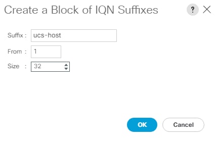
14. Click OK.
15. Click Finish and OK to complete creating the IQN pool.
Create IP Pools for iSCSI Boot
To configure the necessary IP pools for iSCSI boot for the Cisco UCS environment, follow these steps:
![]() The IP Pools for iSCSI Boot are created here in the root organization, assuming that all UCS servers will be booted from the NetApp Infrastructure SVM. If servers will be booted from tenant SVMs with UCS tenant organizations, consider creating the IP Pools for iSCSI Boot in the tenant organization.
The IP Pools for iSCSI Boot are created here in the root organization, assuming that all UCS servers will be booted from the NetApp Infrastructure SVM. If servers will be booted from tenant SVMs with UCS tenant organizations, consider creating the IP Pools for iSCSI Boot in the tenant organization.
1. In Cisco UCS Manager, click LAN.
2. Expand Pools > root.
3. Right-click IP Pools.
4. Choose Create IP Pool.
5. Enter iSCSI-IP-Pool-A as the name of IP pool.
6. Optional: Enter a description for the IP pool.
7. Choose Sequential for the assignment order.
8. Click Next.
9. Click Add to add a block of IP addresses.
10. In the From field, enter the beginning of the range to assign as iSCSI boot IP addresses on Fabric A.
11. Set the size to enough addresses to accommodate the servers.
12. Enter the appropriate Subnet Mask.
13. Click OK.
14. Click Next.
15. Click Finish and OK to complete creating the Fabric A iSCSI IP Pool.
16. Right-click IP Pools.
17. Choose Create IP Pool.
18. Enter iSCSI-IP-Pool-B as the name of IP pool.
19. Optional: Enter a description for the IP pool.
20. Choose Sequential for the assignment order.
21. Click Next.
22. Click Add to add a block of IP addresses.
23. In the From field, enter the beginning of the range to assign as iSCSI IP addresses on Fabric B.
24. Set the size to enough addresses to accommodate the servers.
25. Enter the appropriate Subnet Mask.
26. Click OK.
27. Click Next.
28. Click Finish and OK to complete creating the Fabric B iSCSI IP Pool.
Create iSCSI VLANs
To configure the necessary iSCSI virtual local area networks (VLANs) for the Cisco UCS environment, follow these steps:
1. In Cisco UCS Manager, click LAN.
2. Expand LAN > LAN Cloud.
3. Right-click VLANs.
4. Choose Create VLANs.
5. Enter Infra-iSCSI-A as the name of the VLAN to be used for iSCSI-A.
6. Keep the Common/Global option selected for the scope of the VLAN.
7. Enter the Infra-iSCSI-A VLAN ID.
8. Keep the Sharing Type as None.
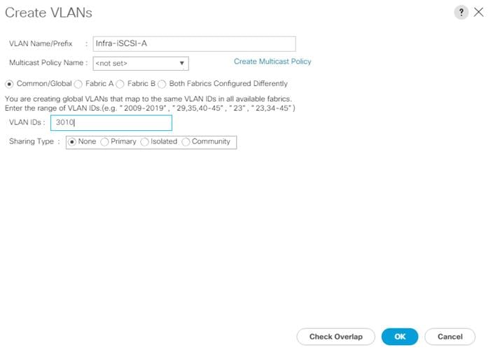
9. Click OK and then click OK again.
10. Right-click VLANs.
11. Choose Create VLANs.
12. Enter Infra-iSCSI-B as the name of the VLAN to be used for iSCSI-B.
13. Keep the Common/Global option selected for the scope of the VLAN.
14. Enter the iSCSI-B VLAN ID.
15. Keep the Sharing Type as None.
16. Click OK and then click OK again.
Create iSCSI vNIC Templates
To create iSCSI virtual network interface card (vNIC) templates for the Cisco UCS environment within the FlexPod Organization, follow these steps:
1. Choose LAN.
2. Expand Policies > root > Sub-Organizations > FlexPod Organization.
3. Right-click vNIC Templates under the FlexPod Organization.
4. Choose Create vNIC Template.
5. Enter iSCSI-A as the vNIC template name.
6. Choose Fabric A. Do not choose the Enable Failover checkbox.
7. Leave Redundancy Type set at No Redundancy.
8. Under Target, make sure that only the Adapter checkbox is selected.
9. Choose Updating Template for Template Type.
10. Under VLANs, choose only Infra-iSCSI-A.
11. Choose Infra-iSCSI-A as the native VLAN.
12. Leave vNIC Name set for the CDN Source.
13. Under MTU, enter 9000.
14. From the MAC Pool list, choose MAC-Pool-A.
15. From the Network Control Policy list, choose Enable-CDP-LLDP.
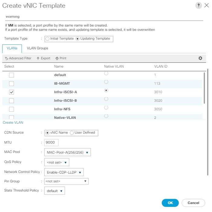
16. Click OK to complete creating the vNIC template.
17. Click OK.
18. Right-click vNIC Templates.
19. Choose Create vNIC Template.
20. Enter iSCSI-B as the vNIC template name.
21. Choose Fabric B. Do not choose the Enable Failover checkbox.
22. Leave Redundancy Type set at No Redundancy.
23. Under Target, make sure that only the Adapter checkbox is selected.
24. Choose Updating Template for Template Type.
25. Under VLANs, choose only Infra-iSCSI-B.
26. Choose Infra-iSCSI-B as the native VLAN.
27. Leave vNIC Name set for the CDN Source.
28. Under MTU, enter 9000.
29. From the MAC Pool list, choose MAC-Pool-B.
30. From the Network Control Policy list, choose Enable-CDP-LLDP.
31. Click OK to complete creating the vNIC template.
32. Click OK.
Create LAN Connectivity Policy for iSCSI Boot
To configure the necessary Infrastructure LAN Connectivity Policy within the FlexPod Organization, follow these steps:
1. In Cisco UCS Manager, click LAN.
2. Expand LAN > Policies > root > Sub-Organizations > FlexPod Organization.
3. Right-click LAN Connectivity Policies under the FlexPod Organization.
4. Choose Create LAN Connectivity Policy.
5. Enter iSCSI-Boot as the name of the policy.
6. Click OK then OK again to create the policy.
7. On the left under LAN > Policies > root > Sub-Organizations > FlexPod Organization > LAN Connectivity Policies, choose iSCSI-Boot.
8. Click Add to add a vNIC.
9. In the Create vNIC dialog box, enter 00-vSwitch0-A as the name of the vNIC.
10. Check the box for Use vNIC Template.
11. In the vNIC Template list, choose vSwitch0-A.
12. In the Adapter Policy list, choose VMWare.
13. Click OK to add this vNIC to the policy.
14. Click Save Changes and OK.
15. Click Add to add another vNIC to the policy.
16. In the Create vNIC box, enter 01-vSwitch0-B as the name of the vNIC.
17. Check the box for Use vNIC Template.
18. In the vNIC Template list, choose vSwitch0-B.
19. In the Adapter Policy list, choose VMWare.
20. Click OK to add the vNIC to the policy.
21. Click Save Changes and OK.
22. Click Add to add a vNIC.
23. In the Create vNIC dialog box, enter 02-vDS0-A as the name of the vNIC.
24. Check the box for Use vNIC Template.
25. In the vNIC Template list, choose vDS0-A.
26. In the Adapter Policy list, choose VMWare-HighTrf.
27. Click OK to add this vNIC to the policy.
28. Click Save Changes and OK.
29. Click Add to add another vNIC to the policy.
30. In the Create vNIC box, enter 03-vDS0-B as the name of the vNIC.
31. Check the box for Use vNIC Template.
32. In the vNIC Template list, choose vDS0-B.
33. In the Adapter Policy list, choose VMWare-HighTrf.
34. Click OK to add the vNIC to the policy.
35. Click Save Changes and OK.
36. Click Add to add a vNIC.
37. In the Create vNIC dialog box, enter 04-iSCSI-A as the name of the vNIC.
38. Check the box for Use vNIC Template.
39. In the vNIC Template list, choose iSCSI-A.
40. In the Adapter Policy list, choose VMWare.
41. Click OK to add this vNIC to the policy.
42. Click Save Changes and OK.
43. Click Add to add a vNIC to the policy.
44. In the Create vNIC dialog box, enter 05-iSCSI-B as the name of the vNIC.
45. Check the box for Use vNIC Template.
46. In the vNIC Template list, choose iSCSI-B.
47. In the Adapter Policy list, choose VMWare.
48. Click OK to add this vNIC to the policy.
49. Click Save Changes and OK.
50. Expand Add iSCSI vNICs.
51. Choose Add in the Add iSCSI vNICs section.
52. Set the name to iSCSI-Boot-A.
53. Choose 04-iSCSI-A as the Overlay vNIC.
54. Set the iSCSI Adapter Policy to default.
55. Leave the VLAN set to Infra-iSCSI-A (native).
56. Leave the MAC Address set to None.
57. Click OK.
58. Click Save Changes and OK.
59. Choose Add in the Add iSCSI vNICs section.
60. Set the name to iSCSI-Boot-B.
61. Choose 05-iSCSI-B as the Overlay vNIC.
62. Set the iSCSI Adapter Policy to default.
63. Leave the VLAN set to Infra-iSCSI-B (native).
64. Leave the MAC Address set to None.
65. Click OK.
66. Click Save Changes and then click OK.
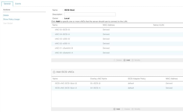
Create iSCSI Boot Policy
This procedure applies to a Cisco UCS environment in which two iSCSI logical interfaces (LIFs) are on cluster node 1 (iscsi-lif-01a and iscsi-lif-01b) and two iSCSI LIFs are on cluster node 2 (iscsi-lif-02a and iscsi-lif-02b). Also, it is assumed that the A LIFs are in the iSCSI-A VLAN and the B LIFs are in the iSCSI-B VLAN.
![]() One boot policy is configured in this procedure. The policy configures the primary target to be iscsi-lif01a.
One boot policy is configured in this procedure. The policy configures the primary target to be iscsi-lif01a.
To create a boot policy for the Cisco UCS environment within the FlexPod Organization, follow these steps:
1. In Cisco UCS Manager, click Servers.
2. Expand Policies > root > Sub-Organizations > FlexPod Organization.
3. Right-click Boot Policies under the FlexPod Organization.
4. Choose Create Boot Policy.
5. Enter Boot-iSCSI-A as the name of the boot policy.
6. Optional: Enter a description for the boot policy.
7. Do not choose the Reboot on Boot Order Change checkbox.
8. Choose the Uefi Boot Mode.
9. Check the box for Boot Security.
10. Expand the Local Devices drop-down menu and click Add Remote CD/DVD.
11. Expand the iSCSI vNICs drop-down menu and click Add iSCSI Boot.
12. In the Add iSCSI Boot dialog box, enter iSCSI-Boot-A.
13. Click OK.
14. Choose Add iSCSI Boot.
15. In the Add iSCSI Boot dialog box, enter iSCSI-Boot-B.
16. Click OK.
17. Expand CIMC Mounted Media and select Add CIMC Mounted CD/DVD.
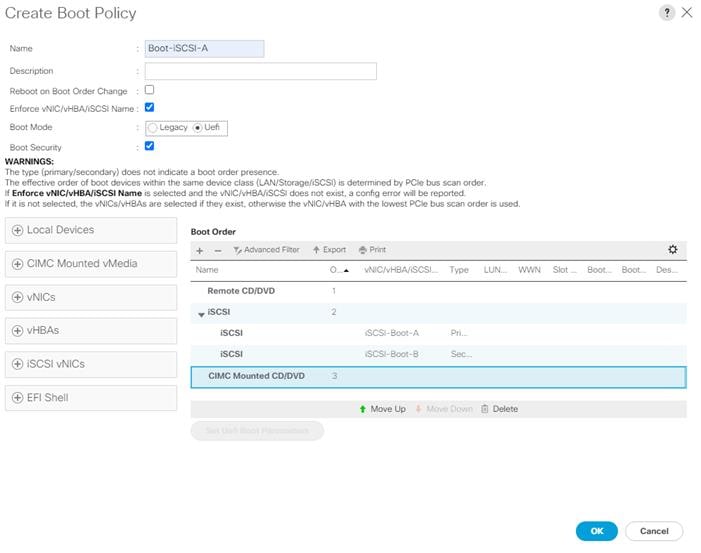
18. Expand iSCSI and select iSCSI-Boot-A. Select Set Uefi Boot Parameters.
![]() For Cisco UCS M5 and M6 servers it is not necessary to set the Uefi Boot Parameters. These servers will boot properly with or without these parameters set. However, for Cisco UCS M4 and earlier servers, VMware ESXi 7.0 will not boot with Uefi Secure Boot unless these parameters are set exactly as shown.
For Cisco UCS M5 and M6 servers it is not necessary to set the Uefi Boot Parameters. These servers will boot properly with or without these parameters set. However, for Cisco UCS M4 and earlier servers, VMware ESXi 7.0 will not boot with Uefi Secure Boot unless these parameters are set exactly as shown.
19. Fill in the Set Uefi Boot Parameters exactly as shown in the following screenshot:
20. Click OK to complete setting the Uefi Boot Parameters for the SAN Boot Target and click OK for the confirmation.
21. Repeat steps 1 - 20 to set Uefi Boot Parameters for each of the 2 iSCSI Boot Targets.
22. Click OK then click OK again to create the policy.
Create iSCSI Boot Service Profile Template
In this procedure, one service profile template for Infrastructure ESXi hosts within the FlexPod Organization is created for Fabric A boot.
To create the service profile template, follow these steps:
1. In Cisco UCS Manager, click Servers.
2. Expand Service Profile Templates > root > Sub-Organizations > FlexPod Organization.
3. Right-click the FlexPod Organization.
4. Choose Create Service Profile Template to open the Create Service Profile Template wizard.
5. Enter VM-Host-Infra-iSCSI as the name of the service profile template.
6. Choose the Updating Template option.
7. Under UUID Assignment, choose UUID_Pool.
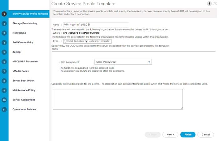
8. Click Next.
Configure Storage Provisioning
To configure the storage provisioning, follow these steps:
1. Click the Local Disk Configuration Policy tab and choose the IgnoreDisk Local Storage Policy.
2. Click Next.
Configure Networking Options
To configure the network options, follow these steps:
1. Choose the “Use Connectivity Policy” option to configure the LAN connectivity.
2. Choose iSCSI-Boot from the LAN Connectivity Policy drop-down list.
3. Choose IQN_Pool in Initiator Name Assignment.
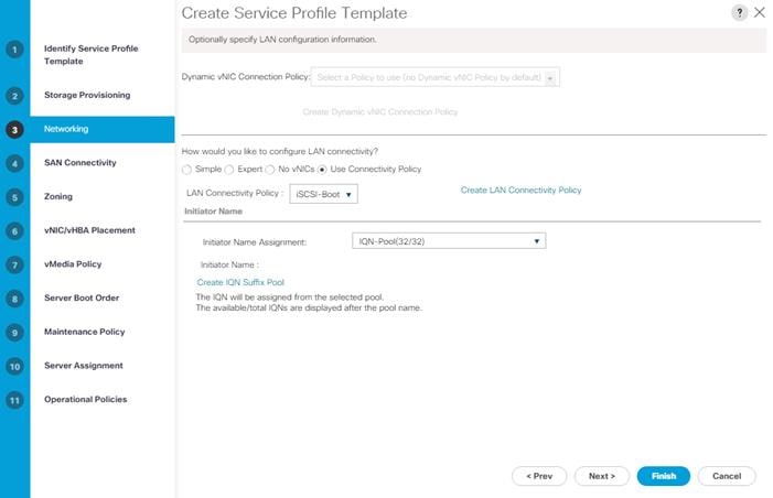
4. Click Next.
Configure Storage Options
To configure the storage options, follow these steps:
1. Choose No vHBAs for the “How would you like to configure SAN connectivity?” field.
2. Click Next.
Configure Zoning Options
To configure the zoning options, follow this step:
1. Make no changes and click Next.
Configure vNIC/HBA Placement
To configure the vNIC/HBA placement, follow these steps:
2. In the “Select Placement” list, leave the placement policy as “Let System Perform Placement”.
3. Click Next.
Configure vMedia Policy
To configure the vMedia policy, follow these steps:
1. Do not select a vMedia Policy.
2. Click Next.
Configure Server Boot Order
To configure the server boot orders, follow these steps:
1. Choose Boot-iSCSI for Boot Policy.
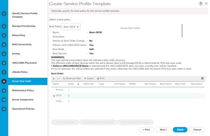
2. In the Boot order, expand iSCSI and choose iSCSI-Boot-A.
3. Click Set iSCSI Boot Parameters.
4. In the Set iSCSI Boot Parameters pop-up, leave Authentication Profile to <not set> unless you have in-dependently created one appropriate to your environment.
5. Leave the “Initiator Name Assignment” dialog box <not set> to use the single Service Profile Initiator Name defined in the previous steps.
6. Set iSCSI-IP-Pool-A as the “Initiator IP address Policy.”
7. Choose iSCSI Static Target Interface option.
8. Click Add.
9. Enter the iSCSI Target Name. To get the iSCSI target name of Infra-SVM, log into the storage cluster management interface and run the “iscsi show” command”.
10. Enter the IP address of iscsi-lif-01a for the IPv4 Address field.
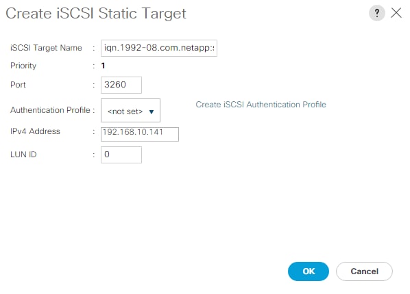
11. Click OK to add the iSCSI static target.
12. Click Add.
13. Enter the iSCSI Target Name.
14. Enter the IP address of iscsi-lif-02a for the IPv4 Address field.
15. Click OK to add the iSCSI static target.
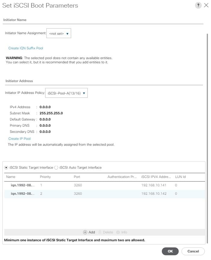
16. Click OK to complete setting the iSCSI Boot Parameters.
17. In the Boot order, choose iSCSI-Boot-B.
18. Click Set iSCSI Boot Parameters.
19. In the Set iSCSI Boot Parameters pop-up, leave Authentication Profile to <not set> unless you have in-dependently created one appropriate to your environment.
20. Leave the “Initiator Name Assignment” dialog box <not set> to use the single Service Profile Initiator Name defined in the previous steps.
21. Set iSCSI-IP-Pool-B as the “Initiator IP address Policy”.
22. Choose the iSCSI Static Target Interface option.
23. Click Add.
24. Enter the iSCSI Target Name. To get the iSCSI target name of Infra-SVM, login into storage cluster management interface and run “iscsi show” command”.
25. Enter the IP address of iscsi-lif-01b for the IPv4 Address field.
26. Click OK to add the iSCSI static target.
27. Click Add.
28. Enter the iSCSI Target Name.
29. Enter the IP address of iscsi-lif-02b for the IPv4 Address field.
30. Click OK to add the iSCSI static target.
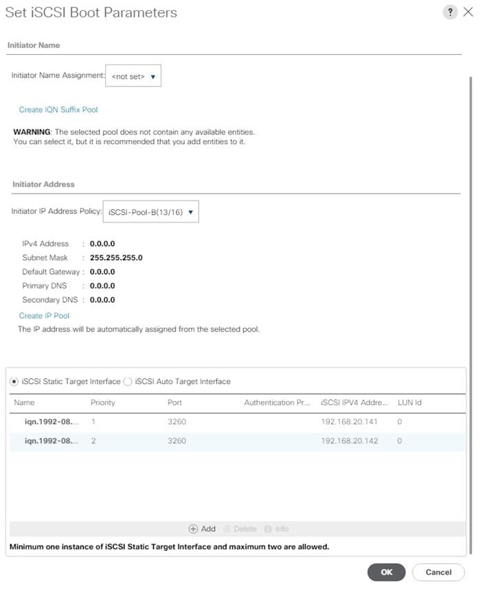
31. Click OK to complete setting the iSCSI Boot Parameters.
32. Click Next.
Configure Maintenance Policy
To configure the maintenance policy, follow these steps:
1. Change the Maintenance Policy to default.
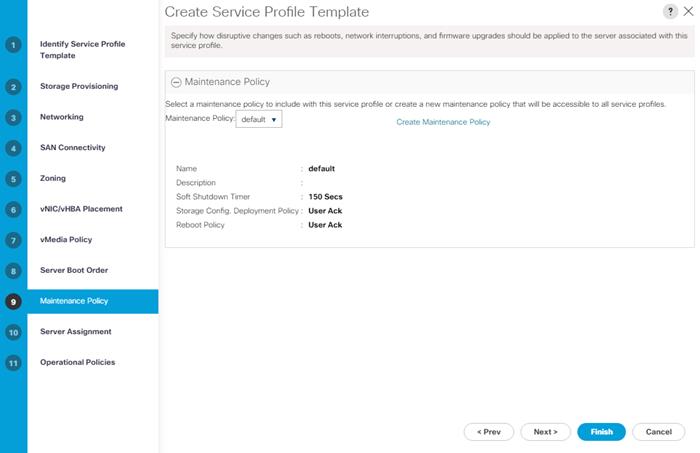
2. Click Next.
Configure Server Assignment
To configure server assignment, follow these steps:
1. In the Pool Assignment list, choose Infra-Pool.
2. Choose Down as the power state to be applied when the profile is associated with the server.
3. Optional: choose “UCS-B200M6” for the Server Pool Qualification to select only UCS B200M6 servers in the pool.
4. Expand Firmware Management at the bottom of the page and choose the default policy.
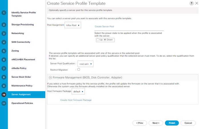
5. Click Next.
Configure Operational Policies
To configure the operational policies, follow these steps:
1. In the BIOS Policy list, choose the BIOS policy for the type of server that you have.
2. Expand External IPMI/Redfish Management Configuration and select IPMI-Profile for the IPMI/Redfish Access Profile.
3. Expand Power Control Policy Configuration and choose No-Power-Cap in the Power Control Policy list.
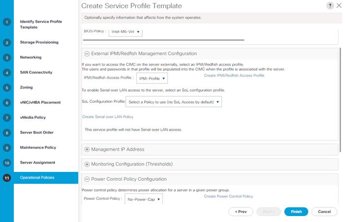
4. Click Finish to create the service profile template.
5. Click OK in the confirmation message.
Create vMedia-Enabled Service Profile Template
To create a service profile template with vMedia enabled, follow these steps:
1. Connect to Cisco UCS Manager and click Servers.
2. Choose Service Profile Templates > root > Sub-Organizations > FlexPod Organization > Service Template VM-Host-Infra-iSCSI.
3. Right-click VM-Host-Infra-iSCSI and click Create a Clone.
4. Name the clone VM-Host-Infra-iSCSI-vM and click OK then click OK again to create the clone.
5. Choose the newly created VM-Host-Infra-iSCSI-vM and choose the vMedia Policy tab.
6. Click Modify vMedia Policy.
7. Choose the ESXi-7U2—CC-HTTP vMedia Policy and click OK.
8. Click OK to confirm.
This same cloning process can be used to create other Service Profile templates that can be modified to accommodate additional features such as Intel Datacenter Persistent Memory (DCPMem) in Memory or App-Direct Mode.
Create Service Profiles
To create service profiles from the service profile template, follow these steps:
1. Connect to Cisco UCS Manager and click Servers.
2. Expand Service Profile Templates > root > Sub-Organizations > FlexPod Organization.
3. Right-click the appropriate vMedia-enabled template and choose Create Service Profiles from Template.
4. For Naming Prefix, enter VM-Host-Infra-0.
5. For Name Suffix Starting Number, enter 1.
6. For Number of Instances, enter 3.
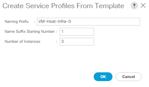
7. Click OK to create the service profiles.
8. Click OK in the confirmation message.
![]() When VMware ESXi 7.0U2 has been installed on the hosts, the host Service Profiles can be bound to the corresponding non-vMedia-enabled Service Profile Template to remove the vMedia Mapping from the host.
When VMware ESXi 7.0U2 has been installed on the hosts, the host Service Profiles can be bound to the corresponding non-vMedia-enabled Service Profile Template to remove the vMedia Mapping from the host.
NetApp Storage Configuration – Part 2
To configure the storage, follow these steps:
1. Edit the following variable file and update the iscsi_igroups variables:
FlexPod-M6/FlexPod-UCSM-M6/vars/ontap_main.yml
![]() Add the host IQNs in the iscsi iGroup variable for iSCSI SAN Boot.
Add the host IQNs in the iscsi iGroup variable for iSCSI SAN Boot.
2. From /root/ FlexPod-M6/FlexPod-UCSM-M6, invoke the ansible scripts for this section use the following command:
ansible-playbook -i inventory Setup_ONTAP.yml -t ontap_config_part_2
![]() Use the -vvv tag to see detailed execution output log.
Use the -vvv tag to see detailed execution output log.
Ansible will implement all the Storage configurations tasks in this section. If implementing an Ansible configuration, skip the following manual steps and go to section Vmware vSphere Configuration.
Create igroups
After the boot LUNs have been created for the three ESXi management hosts, create igroups by following these steps:
| SVM Name |
SVM Target IQN |
| Infra-SVM |
|
Table 16. iSCSI vNIC IQN Configuration
| Cisco UCS Service Profile Name |
iSCSI IQN |
Variable |
| VM-Host-Infra-01 |
|
<vm-host-infra-01-iqn> |
| VM-Host-Infra-02 |
|
<vm-host-infra-02-iqn> |
| VM-Host-Infra-03 |
|
<vm-host-infra-03-iqn> |
1. To obtain the iSCSI vNIC IQN information in Cisco UCS Manager GUI, go to Servers > Service Profiles > root. Click each service profile and then click the iSCSI vNICs tab. The Initiator Name is displayed at the top of the page under the Service Profile Initiator Name.
2. Create igroups by entering the following commands from the storage cluster management LIF SSH connection:
lun igroup create –vserver <infra-data-svm> –igroup VM-Host-Infra-01 –protocol iscsi –ostype vmware –initiator <vm-host-infra-01-iqn>
lun igroup create –vserver <infra-data-svm> –igroup VM-Host-Infra-02 –protocol iscsi –ostype vmware –initiator <vm-host-infra-02-iqn>
lun igroup create –vserver <infra-data-svm> –igroup VM-Host-Infra-03 –protocol iscsi –ostype vmware –initiator <vm-host-infra-03-iqn>
3. To view the two igroups just created, use the command lun igroup show:
lun igroup show -protocol iscsi
Map Boot LUNs to igroups
From the storage cluster management LIF SSH connection, run the following commands:
lun mapping create –vserver <infra-data-svm> –path /vol/esxi_boot/VM-Host-Infra-01 –igroup VM-Host-Infra-01 –lun-id 0
lun mapping create –vserver <infra-data-svm> –path /vol/esxi_boot/VM-Host-Infra-02 –igroup VM-Host-Infra-02 –lun-id 0
lun mapping create –vserver <infra-data-svm> –path /vol/esxi_boot/VM-Host-Infra-03 –igroup VM-Host-Infra-03 –lun-id 0
NetApp Storage Configuration – Part 3
Execute the final Part 3 on NetApp ONTAP Storage configuration.
To invoke the ansible scripts, run the following command:
ansible-playbook -i inventory Setup_ONTAP.yml -t ontap_config_part_3
Configure DNS
To configure DNS for the Infra_SVM, run the following commands:
dns create -vserver <vserver name> -domains <dns-domain> -nameservers <dns-servers>
dns create -vserver Infra_SVM -domains flexpod.cisco.com -nameservers 10.1.156.250,10.1.156.251
Delete Residual Default Broadcast Domains (Applicable for 2-node cluster only)
To delete the Default broadcast domains that are not in use, run the following commands:
broadcast-domain delete -broadcast-domain <broad-domain-name>
broadcast-domain delete -broadcast-domain Default-1
Test AutoSupport
To test the AutoSupport configuration, send a message from all nodes of the cluster, by running the following command:
autosupport invoke -node * -type all -message “FlexPod storage configuration completed”
Set Up VMkernel Ports and Virtual Switch on ESXi Host VM-Host-Infra-01
To add the iSCSI networking configuration on the first ESXi host, follow the steps at the end of section Set Up VMkernel Ports and Virtual Switch. In this section, the iSCSI Boot vSwitch created during the VMware installation is modified and used to connect to UCS fabric A and a second vSwitch is added to connect to fabric B. Two vSwitches is the simplest, easiest to troubleshoot configuration. Other configurations are also valid, such as moving the iSCSI VMkernel ports to pinned port groups on a virtual distributed switch.
To setup VMkernel ports and virtual switches on ESXi hosts on VM-Host-Infra-01, follow these steps:
1. From the Host Client Navigator, click Networking.
2. In the center pane, choose the Virtual switches tab.
3. Highlight the iScsiBootvSwitch line.
4. Choose Edit settings.
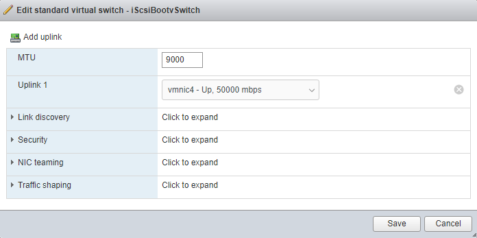
6. Click Save to save the changes to iScsiBootvSwitch.
7. Choose Add standard virtual switch.
8. Name the switch vSwitch1.
9. Change the MTU to 9000.
10. From the drop-down list select vmnic5 for Uplink 1.
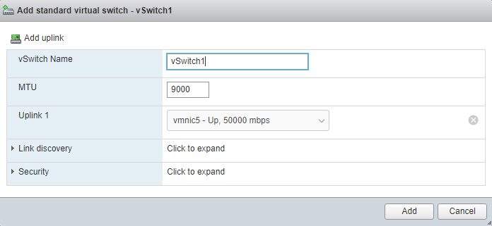
11. Choose Add to add vSwitch1.
12. In the center pane, choose the VMkernel NICs tab.
13. Highlight the iScsiBootPG line.
14. Choose Edit settings.
15. Change the MTU to 9000.
16. Expand IPv4 Settings and enter a unique IP address in the Infra-iSCSI-A subnet but outside of the Cisco UCS iSCSI-IP-Pool-A.
![]() It is recommended to enter a unique IP address for this VMkernel port to avoid any issues related to IP Pool reassignments in Cisco UCS.
It is recommended to enter a unique IP address for this VMkernel port to avoid any issues related to IP Pool reassignments in Cisco UCS.
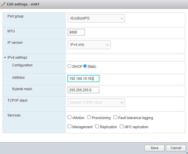
17. Click Save to save the changes to iScsiBootPG VMkernel NIC.
18. Choose Add VMkernel NIC.
19. For New port group, enter iScsiBootPG-B.
20. For Virtual switch, use the pull-down to choose vSwitch1.
21. Change the MTU to 9000.
22. For IPv4 settings, choose Static.
23. Expand IPv4 Settings and enter a unique IP address in the Infra-iSCSI-B subnet but outside of the Cisco UCS iSCSI-IP-Pool-B.
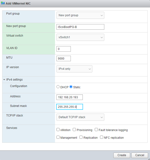
24. Click Create to complete creating the VMkernel NIC.
25. In the center pane, choose the Port groups tab.
26. Highlight the iScsiBootPG line.
27. Choose Edit settings.
28. Change the Name to iScsiBootPG-A.
29. Click Save to complete editing the port group name.
30. On the left choose Storage, then in the center pane choose the Adapters tab.
31. Click Software iSCSI to configure software iSCSI for the host.
32. In the Configure iSCSI window, under Dynamic targets, click Add dynamic target.
33. Choose to add address and enter the IP address of iscsi-lif-01a from storage SVM Infra-SVM. Press Return.
34. Repeat steps 32-33 to add the IP addresses for iscsi-lif-02a, iscsi-lif-01b, and iscsi-lif-02b.
35. Click Save configuration.
36. Click Software iSCSI to configure software iSCSI for the host.
37. Verify that four static targets and four dynamic targets are listed for the host.
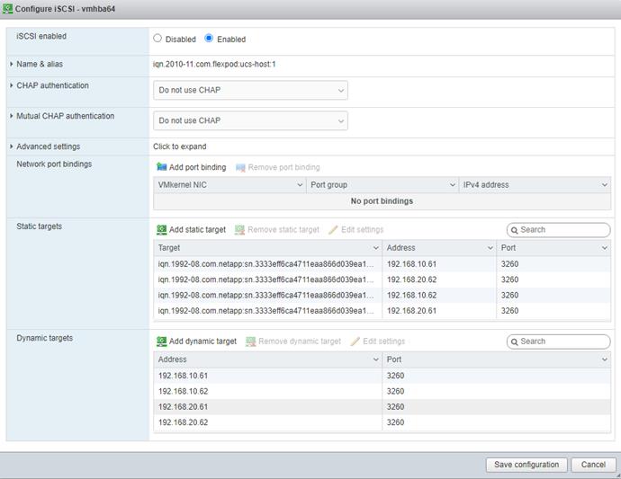
38. Click Cancel to close the window.
Add iSCSI Configuration to a VMware ESXi Host Added in vCenter
This section details the steps to add iSCSI configuration to an ESXi host added and configured in vCenter. This section assumes the host has been added to vCenter and the basic networking completed, NFS datastores set up, and the time configuration and swap files added.
To add an iSCSI configuration to an ESXi host, follow these steps:
1. In the vSphere HTML5 Client, under Hosts and Clusters, choose the ESXi host.
2. In the center pane, click Configure. In the list under Networking, select Virtual switches.
3. In the center pane, expand iScsiBootvSwitch. Click EDIT to edit settings for the vSwitch.
4. Change the MTU to 9000 and click OK.
5. Choose … > Edit Settings to the right of iScsiBootPG. Change the Network label to iScsiBootPG-A and click OK.
6. Choose … > Edit Settings to the right of the VMkernel Port IP address. Change the MTU to 9000.
7. Click IPv4 settings on the left. Change the IP address to a unique IP address in the Infra-iSCSI-A subnet but outside of the Cisco UCS iSCSI-IP-Pool-A.
![]() It is recommended to enter a unique IP address for this VMkernel port to avoid any issues related to IP Pool reassignments.
It is recommended to enter a unique IP address for this VMkernel port to avoid any issues related to IP Pool reassignments.
8. Click OK.
9. In the upper right-hand corner, choose ADD NETWORKING to add another vSwitch.
10. Make sure VMkernel Network Adapter is selected and click NEXT.
11. Choose New standard switch and change the MTU to 9000. Click NEXT.
12. Choose ![]() to add an adapter. Make sure vmnic5 is highlighted and click OK. vmnic5 should now be under Active adapters. Click NEXT.
to add an adapter. Make sure vmnic5 is highlighted and click OK. vmnic5 should now be under Active adapters. Click NEXT.
13. Enter iScsiBootPG-B for the Network label, leave VLAN ID set to None (0), choose Custom – 9000 for MTU, and click NEXT.
14. Choose Use static IPv4 settings. Enter a unique IP address and netmask in the Infra-iSCSI-B subnet but outside of the Cisco UCS iSCSI-IP-Pool-B. Click NEXT.
15. Click FINISH to complete creating the vSwitch and the VMkernel port.
16. In the list under Storage, choose Storage Adapters.
17. Choose the iSCSI Software Adapter and below, choose the Dynamic Discovery tab.
18. Click Add.
19. Enter the IP address of the storage controller’s Infra-SVM LIF iscsi-lif-01a and click OK.
20. Repeat this process to add the IPs for iscsi-lif-02a, iscsi-lif-01b, and iscsi-lif-02b.
21. Under Storage Adapters, click Rescan Adapter to rescan the iSCSI Software Adapter.
22. Under Static Discovery, four static targets should now be listed.
23. Under Paths, four paths should now be listed with two of the paths having the “Active (I/O)” Status.
Create a FlexPod ESXi Custom ISO using VMware vCenter
In this validation document, the Cisco Custom Image for ESXi 7.0 U2 Install CD was used to install VMware ESXi. After this installation the Cisco UCS VIC drivers, Cisco UCS Tools and the NetApp NFS Plug-in for VMware VAAI had to be installed or updated during the FlexPod deployment. vCenter 7.0U2 or later can be used to produce a FlexPod custom ISO containing the updated UCS VIC drivers, UCS Tools and the NetApp NFS Plug-in for VMware VAAI. This ISO can be used to install VMware ESXi 7.0U2 without having to do any additional driver updates. This ISO can be produced by following these steps:
1. Download the Cisco Custom Image for ESXi 7.0 U2 Offline Bundle. This file (VMware_ESXi_7.0.2_17867351_Custom_Cisco_4.1.3_a_Bundle.zip) can be used to produce the FlexPod ESXi 7.0U2 CD ISO.
2. Download the following listed .zip files:
● VMware ESXi 7.0 nfnic 5.0.0.12 Driver for Cisco VIC Adapters – Cisco-nfnic_5.0.0.12-1OEM.700.1.0.15843807_18369224.zip – extracted from the downloaded zip
● UCS Tools Component for ESXi 7.0 1.2.1 - ucs-tool-esxi_1.2.1-1OEM.zip
● NetApp NFS Plug-in for VMware VAAI 2.0 – NetAppNasPluginV2.0.zip
![]() The Cisco VIC nenic driver would also normally be downloaded and added to the FlexPod Custom ISO, but the 1.0.35.0 nenic driver is already included in the Cisco Custom ISO.
The Cisco VIC nenic driver would also normally be downloaded and added to the FlexPod Custom ISO, but the 1.0.35.0 nenic driver is already included in the Cisco Custom ISO.
3. Log into the VMware vCenter HTML5 Client as administrator@vsphere.local.
4. Under Menu, choose Auto Deploy.
5. If you see the following, choose ENABLE IMAGE BUILDER.
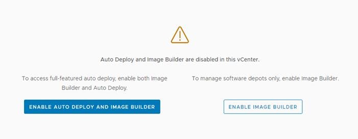
6. Click IMPORT to upload a software depot.
7. Name the depot “Cisco Custom ESXi 7.0U2”. Click BROWSE. Browse to the local location of the VMware_ESXi_7.0.2_17867351_Custom_Cisco-4.1.3_a_Bundle.zip file downloaded above, highlight it, and click Open.
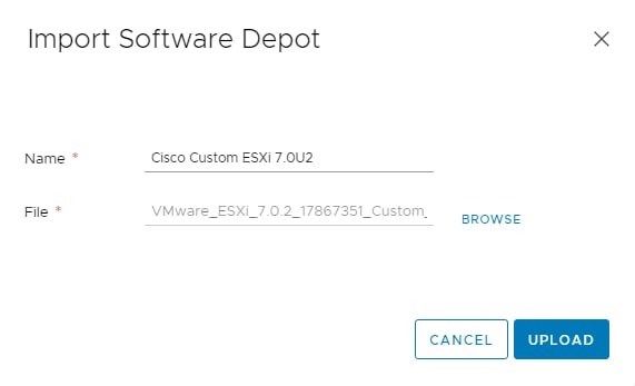
8. Click UPLOAD to upload the software depot.
9. Repeat steps 1 - 8 to add software depots for Cisco-nfnic_5.0.0.15-1OEM.700.1.0.15843807_18697950.zip, ucs-tool-esxi_1.2.1-1OEM.zip, and NetAppNasPluginV2.0.zip.
10. Click NEW to add a custom software depot.
11. Choose Custom depot and name the custom depot FlexPod-ESXi-7.0U2.
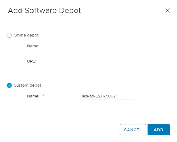
12. Click ADD to add the custom software depot.
13. From the drop-down list, choose the Cisco Custom ESXi-7.0U2 (ZIP) software depot. Make sure the Image Profiles tab is selected and then click the radio button to select the Cisco-UCS-Custom-ESXi-70U2-17867351_4.1.3-a image profile. Click CLONE to clone the image profile.
14. Name the clone FlexPod-ESXi-7.0U2. For Vendor, enter Cisco-NetApp. For Description, enter “Cisco Custom ISO ESXi 7.0U2 with Cisco VIC nfnic 5.0.0.12, UCS Tool-1.2.1 and NetAppNasPluginv2.0”. Choose FlexPod-ESXi-7.0U2 for Software depot.
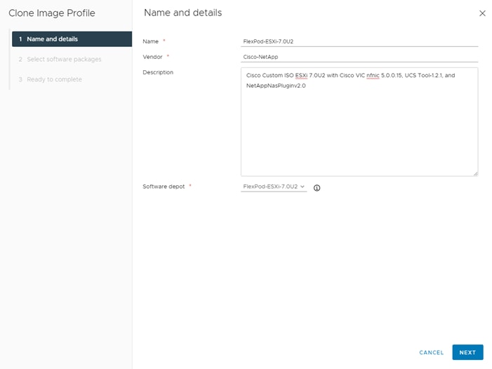
15. Click NEXT.
16. Under Available software packages, check NetAppNasPlugin 2.0-15, nfnic 5.0.0.15, and ucs-tool-esxi 1.2.1. Uncheck nfnic 4.0.0.65 and ucs-tool-esxi 1.1.6. Leave the remaining selections unchanged.
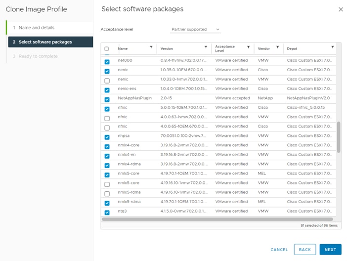
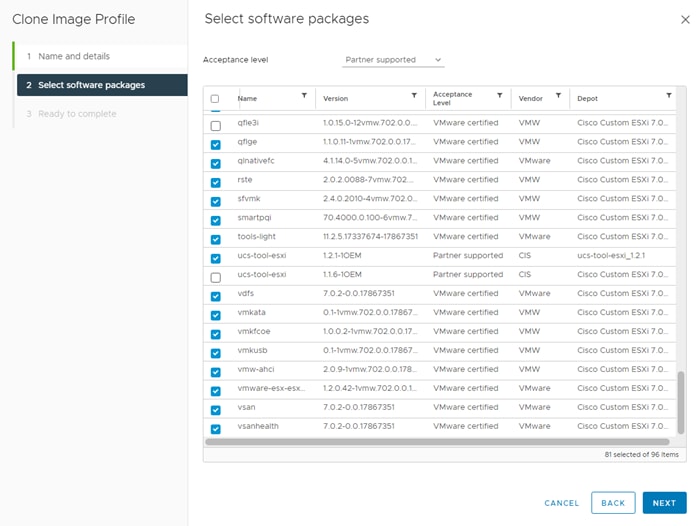
17. Click NEXT.
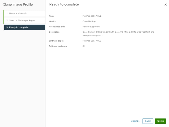
18. Click FINISH.
19. Using the Software Depot pulldown, choose the FlexPod-ESXi-7.0U2 (Custom) software depot. Under Image Profiles choose the FlexPod-ESXi-7.0U2 image profile. Click EXPORT to export an image profile. ISO should be selected. Click OK to generate a bootable ESXi installable image.
20. Once the Image profile export completes, click DOWNLOAD to download the ISO.
21. Once downloaded, you can rename the ISO to a more descriptive name.
22. Optionally, generate the ZIP archive to generate an offline bundle for the FlexPod image using … > Export.
Automated backup of the UCS domain is important for recovery of the UCS Domain from issues ranging catastrophic failure to human error. There is a native backup solution within Cisco UCS that allows local or remote backup using FTP/TFTP/SCP/SFTP as options.
Backups created can be a binary file containing the Full State, which can be used for a restore to the original or a replacement pair of fabric interconnects. Alternately create the XML configuration file consisting of All configurations, just System configurations, or just Logical configurations of the UCS Domain. For scheduled backups, options will be Full State or All Configuration, backup of just the System or Logical configurations can be manually initiated.
To configure the backup, using the Cisco UCS Manager GUI, follow these steps:
1. Choose Admin within the Navigation pane and choose All.
2. Click the Policy Backup & Export tab within All.
3. For a Full State Backup, All Configuration Backup, or both, specify the following:
a. Hostname: <IP or FQDN of host that will receive the backup>
4. Protocol: [FTP/TFTP/SCP/SFTP]
5. User: <account on host to authenticate>
6. Password: <password for account on host>
7. Remote File: <full path and filename prefix for backup file>
![]() Admin State must be Enabled to fill in the Remote File field.
Admin State must be Enabled to fill in the Remote File field.
8. Admin State: <choose Enable to activate the schedule on save, Disable to disable schedule on Save>
9. Schedule: [Daily/Weekly/Bi Weekly]
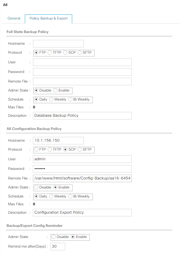
10. Click Save Changes to create the Policy.
The configuration of the Cisco Nexus 9000 and Cisco MDS 9132T switches can be backed up manually at any time with the copy command, but automated backups can be put in place with the NX-OS feature scheduler.
An example of setting up automated configuration backups of one of the FlexPod 93180YC-FX switches is shown below:
conf t
feature scheduler
scheduler logfile size 1024
scheduler job name backup-cfg
copy running-config tftp://<server-ip>/$(SWITCHNAME)-cfg.$(TIMESTAMP) vrf management
exit
scheduler schedule name daily
job name backup-cfg
time daily 2:00
end
![]() On the Cisco MDS 9132T, remove “vrf management” from the copy command.
On the Cisco MDS 9132T, remove “vrf management” from the copy command.
Show the job that has been setup:
show scheduler job
Job Name: backup-cfg
--------------------
copy running-config tftp://10.1.156.150/$(SWITCHNAME)-cfg.$(TIMESTAMP) vrf management
==============================================================================
show scheduler schedule
Schedule Name : daily
---------------------------
User Name : admin
Schedule Type : Run every day at 2 Hrs 0 Mins
Last Execution Time : Yet to be executed
-----------------------------------------------
Job Name Last Execution Status
-----------------------------------------------
backup-cfg -NA-
==============================================================================
copy r s
The documentation for the feature scheduler can be found here: https://www.cisco.com/c/en/us/td/docs/switches/datacenter/nexus9000/sw/93x/system-management/b-cisco-nexus-9000-series-nx-os-system-management-configuration-guide-93x/b-cisco-nexus-9000-series-nx-os-system-management-configuration-guide-93x_chapter_0100001.html
Basic scheduled backup for the vCenter Server Appliance is available within the native capabilities of the VCSA. To create a scheduled backup, follow these steps:
1. Connect to the VCSA Console at https://<VCSA IP>:5480 as root.
2. Click Backup in the list to open the Backup Schedule Dialogue.
3. To the right of Backup Schedule, click CONFIGURE.
4. Specify:
a. The Backup location with the protocol to use (FTPS,HTTPS,SFTP,FTP,NFS,SMB, and HTTP)
b. The User name and password. This can be root and any password. (We used NFSv3 sys security).
c. The Number of backups to retain.
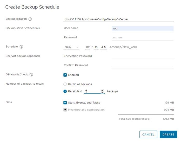
5. Click CREATE.
![]() The Backup Schedule should now show a Status of Enabled.
The Backup Schedule should now show a Status of Enabled.
6. To test the backup setup, you can choose BACKUP NOW and select “Use backup location and user name from backup schedule” to test the backup location.
7. Restoration can be initiated with the backed-up files using the Restore function of the VCSA 7.0 Installer.
John George, Technical Marketing Engineer, Data Center Solutions Engineering, Cisco Systems, Inc.
John has been involved in designing, developing, validating, and supporting the FlexPod Converged Infrastructure since it was developed over ten years ago. Before his role with FlexPod, he supported and administered a large worldwide training network and VPN infrastructure. John holds a master’s degree in Computer Engineering from Clemson University.
Sree Lakshmi Lanka, Senior Technical Marketing Engineer, Hybrid cloud Infrastructures, NetApp
Sree is a Senior Technical Marketing Engineer at NetApp. She has more than 12 years of experience in data center infrastructure solutions, both in traditional and in hybrid/public cloud space. She collaborates with Marketing, Product management and engineering teams to develop and deliver technical marketing product material, which includes Reference Architectures, technical Report, presentations, blogs, demo videos and white papers. This material is aimed at educating customers, partners, or sales team. She has a bachelor’s degree in Computer Science and an artist in the field of Kuchipudi dance, an Indian classical dance form from Andhra Pradesh. She enjoys organic gardening, hiking, and running.
For their support and contribution to the design, validation, and creation of this Cisco Validated Design, the authors would like to thank:
● Haseeb Niazi, Technical Marketing Engineer, Cisco Systems, Inc.
● Arvind Ramakrishnan, Sr. Technical Marketing Engineer, NetApp
● Kamini Singh, Technical Marketing Engineer, NetApp
● Kishore Esanakula, Sr. Technical Marketing Engineer, NetApp
For comments and suggestions about this guide and related guides, join the discussion on Cisco Community at https://cs.co/en-cvds.