-
Cisco Unified Communications SRND Based on Cisco Unified CallManager 4.x
-
Preface
-
Introduction
-
IP Telephony Deployment Models
-
Network Infrastructure
-
Gateways
-
Cisco Unified CallManager Trunks
-
Media Resources
-
Music on Hold
-
Call Processing
-
Call Admission Control
-
Dial Plan
-
Emergency Services
-
Third-Party Voicemail Design
-
Cisco Unity
-
Cisco Unity Express
-
Cisco Unified MeetingPlace Integration
-
Cisco Unified MeetingPlace Express
-
IP Video Telephony
-
LDAP Directory Integration
-
IP Telephony Migration Options
-
Voice Security
-
IP Telephony Endpoints
-
Device Mobility
-
Recommended Hardware and Software Combinations
-
Glossary
-
Index
-
Table Of Contents
Messaging System Infrastructure Components
Port Groups (Separate Integrations)
Cisco Unity and Unity Connection Native Transcoding Operation
Voice Port Integration with a Cisco Unified CallManager Cluster
Voice Port Integration with Dedicated Cisco Unified CallManager Backup Servers
Centralized Messaging and Centralized Call Processing
Distributed Messaging with Centralized Call Processing
Combined Messaging Deployment Models
Centralized Messaging with Clustering Over the WAN
Distributed Messaging with Clustering Over the WAN
Cisco Unity Messaging Failover
Cisco Unity Failover and Clustering Over the WAN
Centralized Messaging with Multiple Cisco Unified CallManager Servers
Cisco Unity
This chapter focuses on the design aspects of integrating Cisco Unity and Cisco Unity Connection with Cisco Unified CallManager. The design topics covered in this chapter apply to both voicemail and unified messaging configurations.
Additionally, this chapter discusses design issues for deploying Cisco Unity with Microsoft Exchange 2000 or 2003 or Lotus Notes Domino message stores and Microsoft Windows 2000 or 2003. This chapter does not cover deployments or upgrades from Microsoft NT 4.0 and/or Exchange 5.5. Cisco Unity Connection has no dependencies on an external message store.
For additional design information about Cisco Unity and Unity Connection, including integrations with other non-Cisco messaging systems, refer to the Cisco Unity Design Guide, available at
This chapter covers the following Cisco Unity and Unity Connection design topics:
•
Messaging System Infrastructure Components
•
•
•
•
•
•
•
•
•
•
•
•
Cisco Unified CallManager Release 4.0 introduced line groups, hunt lists, and hunt pilots, which can impact the operation of existing voice ports. Before upgrading to Cisco Unified CallManager 4.x from Cisco Unified CallManager versions older than Release 4.0, refer to the appropriate Cisco Unified CallManager Administration Guide for your 4.x release, available at
All of the deployment models and design considerations discussed in this chapter are fully supported by the Cisco Unified CallManager 4.x releases.
While Cisco Unified CallManager 4.2 supports SIP trunks, Unity and Unity Connection are not supported for SIP trunk integrations with this release.
Messaging Deployment Models
Cisco Unity supports three primary messaging deployment models:
•
•
Cisco Unity Connection supports single-site messaging and centralized messaging with a single messaging server.
Deployments involving both Cisco Unified CallManager and Cisco Unity or Unity Connection use one call processing model for Cisco Unified CallManager and one messaging model for Cisco Unity. The messaging deployment model is independent from the type of call processing model deployed.
In addition to the three messaging deployment models, Cisco Unity also supports messaging failover. (See Messaging Failover.) Cisco Unity Connection does not currently support failover. Because Cisco Unity Connection uses only a single server without any networking between servers, it supports only the single-site and centralized messaging models.
Cisco Unity supports voicemail only and unified messaging in all messaging models. Cisco Unity Connection supports voicemail only in single-site and centralized messaging models.
Single-Site Messaging
In this model, the messaging systems and messaging infrastructure components are all located at the same site, on the same highly available LAN. The site can be either a single site or a campus site interconnected via high-speed metropolitan area networks (MANs). All clients of the messaging system are also located at the single (or campus) site. The key distinguishing feature of this model is that there are no remote clients.
Centralized Messaging
In this model, similar to the single-site model, all the messaging system and messaging infrastructure components are located at the same site. The site can be one physical site or a campus site interconnected via high-speed MANs. However, unlike the single-site model, centralized messaging clients can be located both locally and remotely.
Because messaging clients may be either local or remote from the messaging system, special design considerations apply to the following graphical user interface (GUI) clients: ViewMail for Outlook (VMO) with Microsoft Exchange and Lotus Notes with Domino Unified Communications Services (DUC) for Cisco. The use of the telephone record and playback (TRaP) and message streaming features should be restricted. Remote clients should not use TRaP and should be configured to download messages before playback because the additional bandwidth usage placed on WAN links cannot be controlled by call admission control. Additionally, because different features and operations for local and remote clients can cause user confusion, TRaP should be disabled on the voice ports and GUI clients should be configured to download messages and not use TRaP, regardless of whether the client is local or remote. Cisco Unity inbox accessed via Cisco Unity Personal Assistant (CPCA) should be allowed only for local clients. The Cisco Unity telephone user interface (TUI) operates the same way for both local and remote clients.
Distributed Messaging
In distributed messaging, the messaging systems and messaging infrastructure components are co-located in a distributed fashion. There can be multiple locations, each with its own messaging system and messaging infrastructure components. All client access is local to each messaging system, and the messaging systems share a messaging backbone that spans all locations. Message delivery from the distributed messaging systems occurs via the messaging backbone through a hub-and-spoke type of message routing infrastructure. No messaging infrastructure components should be separated by a WAN from the messaging system they service. Distributed messaging is essentially multiple, single-site messaging models with a common messaging backbone.
The distributed messaging model has the same design criteria as centralized messaging with regard to local and remote GUI clients, TRaP, and message downloads.
Because Cisco Unity Connection supports only a single server, distribution of messaging servers is not possible with it. Therefore, Cisco Unity Connection does not support the distributed messaging model.
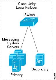
Messaging Failover
All three messaging deployment models support messaging failover. You can implement local messaging failover as illustrated in Figure 13-1. With local failover, both the primary and secondary Cisco Unity servers are located at the same site on the same highly available LAN. This design is only for Cisco Unity; Cisco Unity Connection does not currently support failover.
Figure 13-1 Local Failover of Cisco Unity Messaging
The following list summarize the supported combinations of messaging and call processing models. Cisco Unity and Cisco Unified CallManager support all of the following combinations of messaging and call processing deployment models. Cisco Unity Connection supports all combinations except the distributed messaging models.
•
•
•
•
•
Refer to the Cisco Unity and Cisco Unity Connection design guides available at http://www.cisco.com for further details on site classification and a detailed analysis of supported combinations of messaging and call processing deployment models.
Messaging System Infrastructure Components
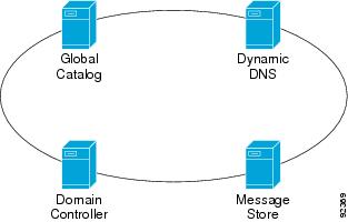
Cisco Unity interacts with various network resources, include Dynamic Domain Name Server (DDNS), directory servers, and message stores. (See Figure 13-2.) Cisco Unity supports both Microsoft Exchange and IBM Lotus Domino as message stores. Each of these message store types has different infrastructure components (refer to the appropriate deployment type in the Cisco Unity Design Guide, available at http://www.cisco.com).
Instead of viewing Cisco Unity as a single monolithic device, it is better to think of it as a system of interdependent components. Each messaging system infrastructure component in a Cisco Unity messaging system is required for normal operation, and it is critical that all of these components be on the same highly available LAN. (In most cases they will be physically co-located.) Any WAN links between these components can introduce delays that will impact the operation of Cisco Unity. These delays will manifest themselves as long delays and periods of silence during TUI operation. For more information, refer to the Network and Infrastructure Considerations chapter in the Cisco Unity Design Guide, available from http://www.cisco.com.
Figure 13-2 Cisco Unity Messaging System Infrastructure Components (Exchange Specific)
Figure 13-2 is a logical representation of the message system infrastructure components. Some of these components can be located on the same server. In the case of IBM Lotus Domino, the message store and directory (Names.nsf) are located on the same server. Microsoft Windows, the global catalog server, and domain controller may also be on the same server. You can also use multiple instances of each component, as in message store clustering, which Cisco Unity supports for Microsoft Exchange 2000 or 2003 and Lotus Domino. All messaging system infrastructure components must be located on the same highly available LAN as the Cisco Unity server(s) that they service.
When deploying Cisco Unity Connection, it is possible to locate the automatic speech recognition (ASR) service on a separate server. In this deployment environment, the Cisco Unity Connection server and the ASR server should reside in the same location. Cisco Unity Connection does not have the same infrastructure requirements or dependencies as Cisco Unity.
Port Groups (Separate Integrations)
Unity Connection introduces the concept of port groups, also known as separate integrations in Cisco Unity 4.2. In earlier releases of Unity, under the Cisco Unity Telephony Integration Manager (UTIM) you were able to configure multiple clusters of the same type of integration. It is important to understand how port groups and separate integrations are different than multiple clusters under a single integration. With the single-integration multiple-cluster approach, the Unity database associated users to an integration, not a cluster. Because there was only a single integration, all subscribers were associated with that single integration regardless of which cluster they were on. For message waiting indication (MWI), Unity then had to broadcast MWI updates out all ports under the single integration, including to clusters where the subscriber was not present. With the new addition of separate integrations in Unity (4.2) and port groups in Unity Connection, subscribers are associated with the specific integration to which they belong. MWI lights no longer have to be broadcast out all ports but are sent only to the specific ports that are associated with the particular subscriber.
Dual integrations occur when you integrate more than one type of system to a Unity or Unity Connection server, such as when integrating a legacy phone system and a Cisco Unified CallManager phone system. Multiple integrations occur when you integrate Cisco Unity 4.1 or earlier versions to more than one Cisco Unified CallManager cluster via the same type of integration, such as when integrating via SCCP to two or more Cisco Unified CallManager clusters.
With Unity 4.2, separate integrations are configured via the UTIM, while for Unity Connection port groups are configured under the System Administrator.
With Cisco Unified CallManager 4.2, SIP integrations to Cisco Unity and Unity Connection are not currently supported. For SIP integrations with Cisco Unified CallManager, refer to the Cisco Unified Communications SRND for Cisco CallManager 5.0, available at
Managing Bandwidth
Cisco Unified CallManager provides a variety of features for managing bandwidth. Through the use of regions, locations, and even gatekeepers, Cisco Unified CallManager can ensure that the number of voice calls going over a WAN link does not oversubscribe the existing bandwidth and cause poor voice quality. Cisco Unity and Unity Connection rely on Cisco Unified CallManager to manage bandwidth and to route calls. If you deploy Cisco Unity or Unity Connection in an environment where calls or voice ports might cross WAN links, these calls will be transparent to gatekeeper-based call admission control. This situation occurs any time the Cisco Unity or Unity Connection server is servicing either distributed clients (distributed messaging (Unity only) or distributed call processing) or when Cisco Unified CallManager is remotely located (distributed messaging (Unity only) or centralized call processing). Cisco Unified CallManager provides regions and locations for call admission control.
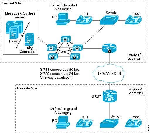
Figure 13-3 uses a small centralized messaging and centralized call processing site to illustrate how regions and locations work together to manage available bandwidth. For a more detailed discussion of regions and locations, refer to the chapter on Call Admission Control, page 9-1.
Figure 13-3 Locations and Regions
In Figure 13-3, regions 1 and 2 are configured to use G.711 for intra-region calls and G.729 for inter-region calls. Locations 1 and 2 are both set to 24 kbps. Location bandwidth is budgeted only in the case of inter-location calls.
An intra-region (G.711) call would not be budgeted against the available bandwidth for the location. For example, when extension 100 calls extension 101, this call is not budgeted against the 24 kbps of available bandwidth for Location 1. However, an inter-region call using G.729 is budgeted against both bandwidth allocations of 24 kbps for Location 1 and Location 2. For example, when extension 100 calls extension 200, this call would be connected but any additional (simultaneous) inter-region calls would receive reorder (busy) tone.
Impact of Non-Delivery of RDNIS on Voicemail Calls Routed via AAR
Automated alternate routing (AAR), a Cisco Unified CallManager feature, can route calls over the PSTN when the WAN is oversubscribed. However, when calls are rerouted over the PSTN, Redirected Dialed Number Information Service (RDNIS) can be affected. Incorrect RDNIS information can impact voicemail calls that are rerouted over the PSTN by AAR when Cisco Unity or Unity Connection is remote from its messaging clients. If the RDNIS information is not correct, the call will not reach the voicemail box of the dialed user but will instead receive the auto-attendant prompt, and the caller might be asked to reenter the extension number of the party they wish to reach. This behavior is primarily an issue when the telephone carrier is unable to ensure RDNIS across the network. There are numerous reasons why the carrier might not be able to ensure that RDNIS is properly sent. Check with your carrier to determine if they provide guaranteed RDNIS deliver end-to-end for your circuits. The alternative to using AAR for oversubscribed WANs is simply to let callers hear reorder tone in an oversubscribed condition.
Cisco Unity and Unity Connection Native Transcoding Operation
By default, the Cisco Unity or Unity Connection server performs transcoding automatically. Currently, Cisco Unified CallManager and Cisco Unity support only G.729 and G.711 for the Skinny Client Control Protocol (SCCP) TAPI Service Provider (TSP) voice ports, and other codecs are supported with legacy integration using Intel or Dialogic voice boards. Cisco Unity native transcoding does not use external hardware transcoders but instead uses the server's main CPU. For SCCP integrations only, the native transcoding must be disabled (turned off) on the Cisco Unity server via a registry setting in order for Cisco Unified CallManager to assign hardware transcoders to voice port calls. The registry setting is called "Audio - Enable G.729a codec support," and the tool for setting it is the Advanced Settings Tool available at http://www.CiscoUnityTools.com. (To disable native transcoding on Cisco Unity Connection, the configuration of the messaging codec is done differently, as described at the end of this section.)
By default, there is no codec registry key, and therefore native transcoding is enabled (on). The Advanced Settings Tool adds a new registry key that enables you to select either one of the two available codecs. Cisco Unity will then "advertise" to Cisco Unified CallManager that it supports only one codec. If a call terminating or originating on the voice ports is using a different codec than the type configured for the Cisco Unity server, Cisco Unified CallManager will assign an external transcoding resource for the call. For detailed information on how to configure transcoding resources on Cisco Unified CallManager, refer to the chapter on Media Resources, page 6-1.
When the Advanced Settings Tool is used to enable only one codec, the Cisco Unity server system prompts must be the same as the codec used. By default, the system prompts are G.711. If the codec is set to G.711, the system prompts will work correctly. However, if G.729 is selected, you will have to change the system prompts. Refer to the Cisco Unity Administration Guide on http://www.cisco.com for details on how to change the system prompts. If the system prompts are not the same as the codec selected by the registry, then the end users will hear unintelligible system prompts.
To change how Cisco Unity Connection advertises which codecs it supports, the configuration is done differently than for Cisco Unity. Instead of using the Cisco Unity Tools Depot, the configuration changes are made from the Cisco Unity Connection Administration page. Under the Telephony Integrations heading, select the Port Groups link. On the Port Groups page, you can change the configuration to advertise either G.711 only, G.729 only, or both, but "prefer" either G.711 or G.729. In the preferred setting, Cisco Unity Connection will advertise that it supports both protocols (native transcoding) but will prefer to use the one specified over the other. With native transcoding disabled, Cisco Unified CallManager will provide a transcoder resource when needed instead of using the CPU on the Unity or Unity Connection server.
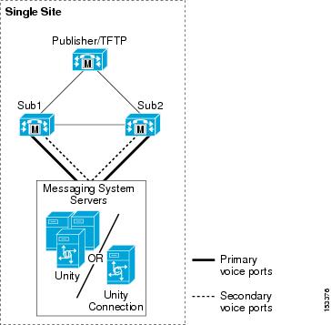
Voice Port Integration with a Cisco Unified CallManager Cluster
When deploying Cisco Unity in a single-site messaging environment, integration with the Cisco Unified CallManager cluster occurs through the SCCP voice ports. Design considerations must include proper deployment of the voice ports among the Cisco Unified CallManager subscribers so that, in the event of a subscriber failure (Cisco Unified CallManager failover), users and outside calls can continue to access voice messaging. (See Figure 13-4.)
Figure 13-4 Cisco Unity Server(s) Integrated with a Cisco Unified CallManager Cluster (No Dedicated Backup Servers)
The Cisco Unified CallManager cluster in Figure 13-4 employs 1:1 server redundancy and 50/50 load balancing. During normal operations, each subscriber server is active and handles up to 50% of the total server call processing load. In the event of a subscriber server failure, the remaining subscriber server takes up the load of the failed server.
This configuration uses two groups of voicemail ports, with each group containing one-half of the total number of licensed voice ports. One group is configured so that its primary server is Sub1 and its secondary (backup) server is Sub2. The second group is configured so that Sub2 is the primary server and Sub1 is the backup.
Make sure that MWI-only ports or any other special ports are equally distributed between the two groups. During the configuration of the voice ports, pay special attention to the naming convention. When configuring the two groups of ports in the Cisco Unity Telephony Integration Manager (UTIM) utility, make sure that the device name prefix is unique for each group and that you use the same device name when configuring the voicemail ports in Cisco Unified CallManager Administration. The device name prefix is unique for each group of ports in this example, with group Sub1 using CiscoUM1 as the device name prefix and Sub2 using CiscoUM2 in this example.
For additional design information on the ratio of inbound to outbound voicemail ports (for MWI, message notification, and TRaP), refer to the Cisco Unity Design Guide available at http://www.cisco.com.
Note
In Cisco Unified CallManager Administration, half of the ports in this example are configured to register using the unique device name prefix of CiscoUM1, and the other half are configured to register using the unique device prefix. (See Table 13-1.) When the ports register with Cisco Unified CallManager, half will be registered with subscriber server Sub1, and the other half will be registered with Sub2, as shown in Table 13-1.
Note
Cisco Unified CallManager 4.0 introduced numerous changes to the configuration of SCCP voicemail ports with regard to how they hunt and forward calls. For information on how these changes impact the voicemail port operation and configuration, refer to the Cisco Unified CallManager 4.0 documentation available at
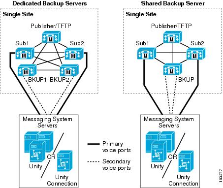
Voice Port Integration with Dedicated Cisco Unified CallManager Backup Servers
This Cisco Unified CallManager cluster configuration allows each subscriber server to operate at a call processing load higher than 50%. Each primary subscriber server has either a dedicated or shared backup server. (See Figure 13-5.) During normal operation the backup server processes no calls, in the event of failure or maintenance of a Subscriber server, the backup server will then take the full load of that server.
Figure 13-5 Cisco Unity Server(s) Integrated with a Single Cisco Unified CallManager Cluster with Backup Subscriber Server(s)
Configuration of the voicemail ports in this case is similar to the 50/50 load-balanced cluster. However instead of configuring the voice ports to use the opposite subscriber server as the secondary server, the individual shared or dedicated backup server is used. In the Cisco Unified CallManager clustered with a shared backup server, both of the secondary ports for the subscribers servers are configured to use the single backup server.
The voice port names (device name prefix) must be unique for each Cisco UTIM group and must be the same as the device names used on the Cisco Unified CallManager server.
To configure the voicemail ports on Cisco Unity, use the UTIM tool. For Cisco Unity Connection, use the Telephony Integration section of the Unity Connection Administration console. For details, refer to the Cisco Unity or Cisco Unity Connection administration guides available at http://www.cisco.com.
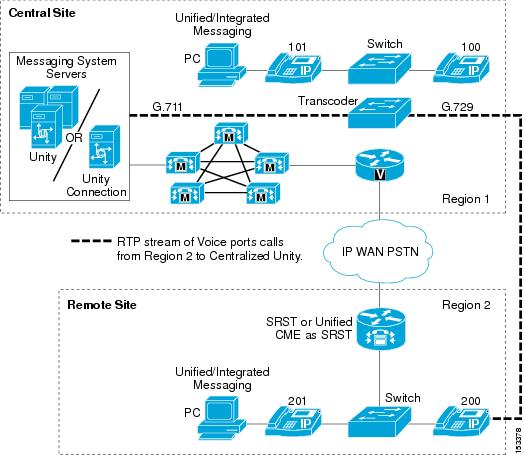
Centralized Messaging and Centralized Call Processing
In centralized messaging, the Cisco Unity server is co-located with the Cisco Unified CallManager cluster. With centralized call processing, subscribers may be located either remotely and/or locally to the cluster and messaging server(s). (See Figure 13-6.) When remote users access resources at the central site (such as voice ports, IP phones, or PSTN gateways, as in Tail-End Hop-Off (TEHO)), these calls are transparent to gatekeeper call admission control. Therefore, regions and locations must be configured in Cisco Unified CallManager for call admission control. (See Managing Bandwidth.) When making inter-region calls to IP phones or MGCP gateways, IP phones automatically select the inter-region codec that has been configured. Native transcoding should be disabled so that the Cisco Unity voice ports use Cisco Unified CallManager transcoding resources for calls that transverse the WAN (inter-region).
Figure 13-6 Centralized Messaging with Centralized Call Processing
In Figure 13-6, regions 1 and 2 are configured to use G.711 for intra-region calls and G.729 for inter-region calls. Native transcoding has been disabled on the Cisco Unity server.
As Figure 13-6 shows, when a call is made from extension 200 to the voicemail ports in Region 1, the inter-region G.729 codec is used at the endpoint but the RTP stream is transcoded to use G.711 on the voice ports. Native transcoding on the Cisco Unity server has been disabled in this example. Cisco Unified CallManager transcoding resources must be located at the same site as the voicemail system.
Hairpinning
Another issue to consider is hairpinning (or tromboning) of voice calls over multiple Cisco Unity voice ports. Hairpinning is not a concern in environments that use only SCCP TSP voice ports, but it is a concern with dual-integration environments, where hairpinning can occur between the voice ports of the legacy system and the SCCP TSP voice ports.
For more information about dual integration, refer to the Cisco Unity Administration Guide, available at
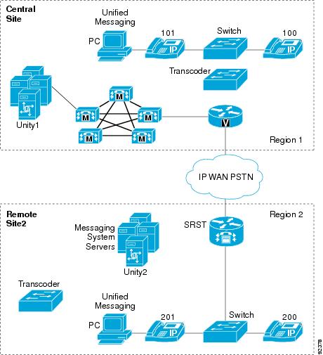
Distributed Messaging with Centralized Call Processing
Distributed messaging means that there are multiple messaging systems distributed within the telephony environment, and each messaging system services only local messaging clients. This model differs from centralized messaging, where clients are both local and remote from the messaging system. Figure 13-7 illustrates the distributed messaging model with centralized call processing. As with other multisite call processing models, the use of regions and locations is require to manage WAN bandwidth. For this model, you must also disable Cisco Unity native transcoding.
Figure 13-7 Distributed Messaging with Centralized Call Processing
For the configuration in Figure 13-7, transcoder resources must be local to each Cisco Unity message system site. Regions 1 and 2 are configured to use G.711 for intra-region calls and G.729 for inter-region calls. Native transcoding has been disabled on the Cisco Unity servers.
Voice messaging ports for both Cisco Unity servers must be assigned the appropriate region and location by means of calling search spaces and device pools configured on the Cisco Unified CallManager server. In addition, to associate telephony users with a specific group of voicemail ports, you must configure Cisco Unified CallManager voicemail profiles. For details on configuring calling search spaces, device pools, and voicemail profiles, refer to the applicable version of the Cisco Unified CallManager Administration Guide, available at
The messaging systems are "networked" together to present a single messaging system to both inside and outside users. For information about Cisco Unity Networking for the distributed Unity servers, Refer to the Networking in Cisco Unity Guide, available at
http://www.cisco.com/en/US/products/sw/voicesw/ps2237/products_feature_guides_list.html
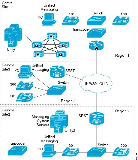
Combined Messaging Deployment Models
It is possible to combine messaging models in the same deployment, provided that the deployment adheres to all the guidelines listed in the preceding sections. Figure 13-8 shows a user environment in which both centralized and distributed messaging are employed simultaneously.
Figure 13-8 Combined Deployment Models
Figure 13-8 shows the combination of two messaging models. Regions 1 and 3 use centralized messaging with centralized call processing, while Region 2 uses distributed messaging with centralized call processing. All regions are configured to use G.711 for intra-regions calls and G.729 for inter-region calls.
In Figure 13-8, centralized messaging and centralized call control are used between the Central Site and Site3. The messaging system at the Central Site provides messaging services for clients at both the Central Site and Site3. Site2 uses the distributed messaging model with centralized call control. The messaging system (Unity2) located at Site2 provides messaging services for only those users located within Site2. In this deployment, both models adhere to their respective design guidelines as presented in this chapter. Transcoding resources are located locally to each messaging system site, and they support clients who access messaging services from a remote site (relative to the messaging system), as in the case of a Site2 user leaving a message for a Central Site user.
Centralized Messaging with Clustering Over the WAN
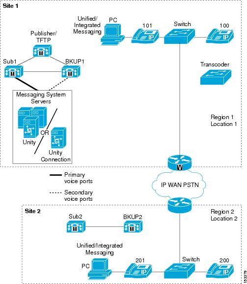
This section addresses Cisco Unity design issues for deploying centralized messaging with Cisco Unified CallManager clustering over the WAN with local failover. In the case of a WAN failure with this model, all remote messaging sites will lose voicemail capability until the WAN is restored. (See Figure 13-9.)
Clustering over the WAN supports local failover. With local failover, each site has a backup subscriber server physically located at the site. This section focuses on deploying Cisco Unity centralized messaging with local failover for clustering over the WAN.
For additional information, refer to the section on Clustering Over the IP WAN, page 2-17.
Figure 13-9 Cisco Unity Centralized Messaging and Clustering Over the WAN with Local Failover
The minimum bandwidth required between cluster sites is a T1 line (1,544 MHz). This amount of bandwidth can support signaling and database traffic for up to 10,000 busy hour call attempts (BHCA), but it does not include the required media bandwidth.
Clustering over the WAN with Cisco CallManager Release 3.3(3) and earlier supports up to four sites per cluster, but Cisco Unified CallManager Release 4.1 and higher supports up to eight sites. Cisco Unity supports up to the maximum number of sites in either case. The voicemail ports are configured only at the site where the Cisco Unity messaging system is located (see Figure 13-9). Voicemail ports do not register over the WAN to the remote site(s). Messaging clients at the other site(s) access all voicemail resources from the primary site. There is no benefit to configuring voice ports over the WAN to any of the remote sites because, in the event of a WAN failure, remote sites would lose access to the centralized messaging system. Because of bandwidth consideration, the voicemail ports should have TRaP disabled and all messaging clients should download voicemail messages to their local PCs (unified messaging only).
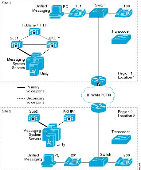
Distributed Messaging with Clustering Over the WAN
Local failover sites that also have Cisco Unity messaging server(s) deployed would have voice ports registered to the local Cisco Unified CallManager subscriber server(s), similar to the centralized messaging model. For information about configuring the voice ports, see Voice Port Integration with a Cisco Unified CallManager Cluster, and Voice Port Integration with Dedicated Cisco Unified CallManager Backup Servers.
Figure 13-10 Cisco Unity Distributed Messaging and Clustering over the WAN with Local Failover
In a purely distributed messaging implementation with clustering over the WAN, each site in the cluster would have its own Cisco Unity messaging server with messaging infrastructure components. If not all of the sites have local Cisco Unity messaging systems but some sites have local messaging clients using a remote messaging server(s), this deployment would be a combination model with both distributed messaging and centralized messaging. (See Combined Messaging Deployment Models.) In the event of a WAN failure in this model, all remote sites that use centralized messaging will lose voicemail capability until the WAN is restored.
Each site that does not have a local messaging server must use a single messaging server for all of its messaging clients, but all such sites do not have to use the same messaging server. For example, suppose Site1 and Site2 each have a local messaging server. Site3 can then have all of its clients use (register with) the messaging server at Site2, while Site4 can have all of its clients use the messaging server at Site1. Transcoder resources are required at sites that have local Cisco Unity messaging server(s).
As with other distributed call processing deployments, calls going between these sites are transparent to gatekeeper call admission control, therefore you must configure regions and locations in Cisco Unified CallManager to provide call admission control. (See Managing Bandwidth.)
The distributed Cisco Unity servers may also be networked digitally. For more information on this topic, refer to the Cisco Unity Networking Guide, available at http://www.cisco.com. The networking guides are specific to the particular messaging store deployed.
Cisco Unity Messaging Failover
Cisco Unity failover provides voicemail survivability in the case of a Cisco Unity server failure. (See Figure 13-1.) With Cisco Unity local failover, both the primary and secondary Unity messaging servers reside at the same physical location, and the messaging infrastructure components are co-located with the primary server. Optionally, messaging infrastructure components (such as messaging store servers, domain controller and global catalog (DC/GC) servers, and DNS servers) can also have redundant components that may be physically co-located with the Cisco Unity secondary server.
Cisco Unity failover is supported by all of the messaging deployment models. Cisco Unity Connection currently does not support failover.
For information on configuring Cisco Unity failover, refer to the Cisco Unity Failover Configuration and Administration Guide, available at
Cisco Unity Failover and Clustering Over the WAN
When deploying Cisco Unity local failover with clustering over the WAN, apply the same design practices described in Centralized Messaging with Clustering Over the WAN, and Distributed Messaging with Clustering Over the WAN. The voice ports from the primary Cisco Unity server should not cross the WAN during normal operation.
Figure 13-11 depicts Cisco Unity local failover. Note that the primary and secondary Cisco Unity servers are both physically located at the same site. Cisco Unity failover supports up to the maximum number of remote sites available with clustering over the WAN for Cisco Unified CallManager.
Note
Figure 13-11 Cisco Unity Local Failover and Clustering Over the WAN
For information on configuring Cisco Unity failover, refer to the Cisco Unity Failover Configuration and Administration Guide, available at
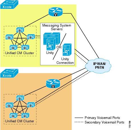
Centralized Messaging with Multiple Cisco Unified CallManager Servers
Cisco Unity and Unity Connection support port groups, which allow subscribers on either of the Unity product servers to be associated with a port group and ultimately an integration. When a subscriber is associated with a particular port group, the MWI function for the user occurs only on the MWI ports belonging to that port group. Cisco Unity supports up to nine port groups, while Cisco Unity Connection supports up to seven port groups. For details, refer to the appropriate Cisco Unity or Cisco Unity Connection administration guides available at http://www.cisco.com.
Figure 13-12 Integrating Cisco Unity or Unity Connection with Multiple Cisco Unified CallManager Clusters
Messaging clients at both Cluster 1 and Cluster 2 sites use the Cisco Unity or Unity Connection messaging infrastructure physically located at Cluster 1. (See Figure 13-12.)