-
Cisco Unified Communications SRND Based on Cisco Unified CallManager 4.x
-
Preface
-
Introduction
-
IP Telephony Deployment Models
-
Network Infrastructure
-
Gateways
-
Cisco Unified CallManager Trunks
-
Media Resources
-
Music on Hold
-
Call Processing
-
Call Admission Control
-
Dial Plan
-
Emergency Services
-
Third-Party Voicemail Design
-
Cisco Unity
-
Cisco Unity Express
-
Cisco Unified MeetingPlace Integration
-
Cisco Unified MeetingPlace Express
-
IP Video Telephony
-
LDAP Directory Integration
-
IP Telephony Migration Options
-
Voice Security
-
IP Telephony Endpoints
-
Device Mobility
-
Recommended Hardware and Software Combinations
-
Glossary
-
Index
-
Table Of Contents
Phone Authentication and Encryption
Port Security: MAC CAM Flooding
Port Security: Prevent Port Access
Port Security: Prevent Rogue Network Extensions
DHCP Snooping: Prevent Rogue DHCP Server Attacks
DHCP Snooping: Prevent DHCP Starvation Attacks
DHCP Snooping: Binding Information
Requirement for Dynamic ARP Inspection
Putting Firewalls Around Gateways
ASA and PIX Configuration Example
Cisco Security Agent on the Cisco Unified CallManager and Application Servers
Unmanaged Cisco Security Agent
Firewall Deployment Example (Centralized Deployment)
Voice Security
This chapter presents guidelines and recommendations for securing IP Telephony networks. Following the guidelines in this chapter does not guarantee a secure environment, nor will it prevent all penetration attacks on a network. You can achieve reasonable security by establishing a good security policy, following that security policy, staying up-to-date on the latest developments in the hacker and security communities, and maintaining and monitoring all systems with sound system administration practices.
The security guidelines presented in this chapter pertain specifically to IP Telephony technology and the voice network. For more information on data network security, refer to the Cisco SAFE Blueprint documentation available at
This chapter addresses centralized but not distributed call processing, and it includes clustering over the WAN but not local failover mechanisms such as Survivable Remote Site Telephony (SRST). This chapter assumes that all remote sites have a redundant link to the head-end or local call-processing backup in case of head-end failure. The interaction between Network Address Translation (NAT) and IP Telephony, for the most part, is not addressed here. This chapter also assumes that all networks are privately addressed and do not contain overlapping IP addresses.
General Security
This section covers general security features and practices that can be used to protect the voice data within a network.
Security Policy
This chapter presumes that your enterprise already has a security policy in place. Cisco Systems recommends that you do not deploy any technology without an associated security policy. The security policy defines which data in your network is sensitive so that it can be protected properly when transported throughout the network. Having this security policy helps you define the security levels required for the types of data traffic that are on your network. Each type of data may or may not require its own security policy.
If no security policy exists for data on the company network, you should create one before enabling any of the security recommendations in this chapter. Without a security policy, there is no way of telling if the security that is enabled in a network is doing what it is designed to accomplish. Without a security policy, there is also no systematic way of enabling security for all the applications and types of data that run in a network.
Note
While it is important to adhere to the security guidelines and recommendations presented in this chapter, they alone are not sufficient to constitute a security policy for your company. You must define a corporate security policy before implementing any security technology.
This chapter details the features and functionality of a Cisco Systems network that are available to protect the voice data on a network. It is up to the security policy to define which data to protect, how much protection is needed for that type of data, and which security techniques to use to provide that protection.
One of the more difficult issues with a security policy that includes IP Telephony is combining the security policies that usually exist for both the data network and the traditional voice network. Ensure that all aspects of the integration of the voice data onto the network are secured at the correct level for your security policy or corporate environment.
The basis of a good security policy is defining how important your data is within the network. Once you have ranked the data according to its importance, you can decide how the security levels should be established for each type of data. You can then achieve the correct level of security by using both the network and application features.
In summary, you can use the following process to define a security policy:
•
•
•
Security in Layers
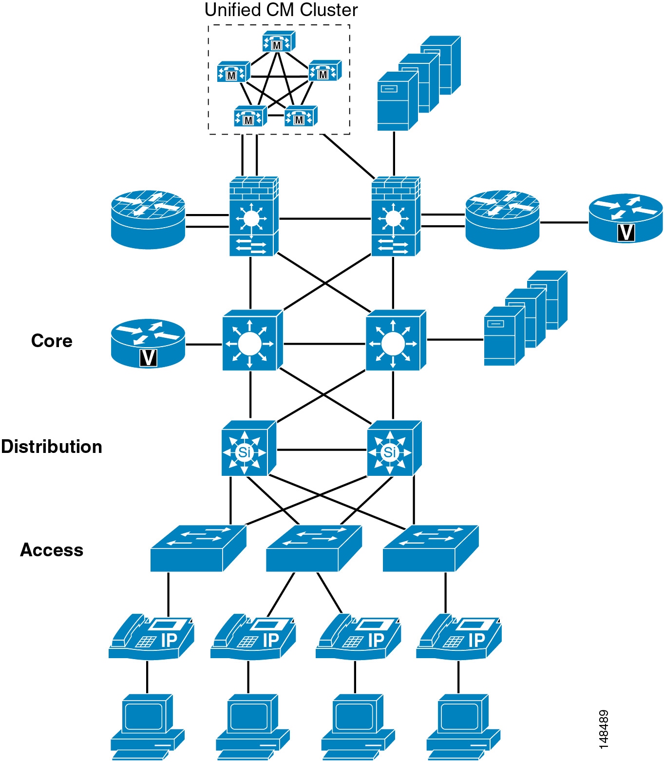
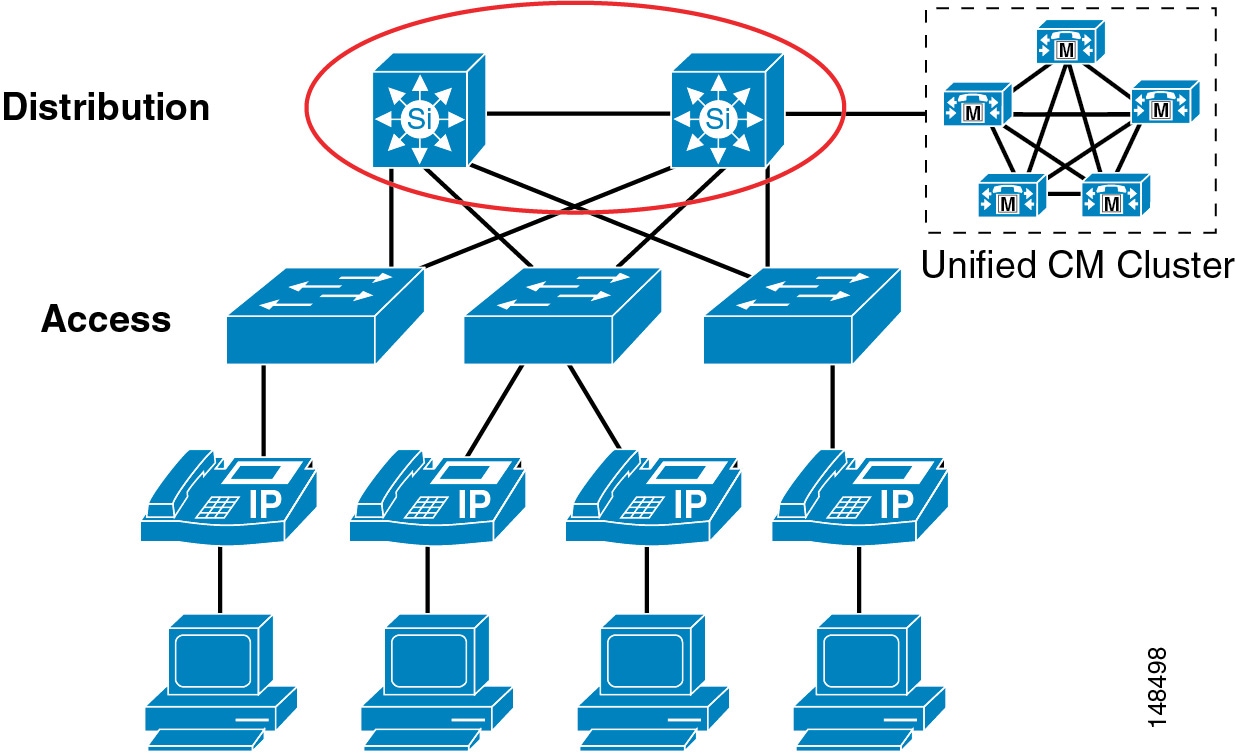
This chapter starts at the phone port that a user can plug a PC into, and it works its way through the network from the phone to the access switch, to the distribution layer, into the core, and then into the data center. (See Figure 20-1.) We build layer upon layer of security, starting at the access port into the network itself. With each feature or function that is discussed, we list advantages and disadvantages that need to be taken into account from the standpoint of your corporate security policy.
For example, Figure 20-1 shows both the advantage and disadvantage of using an IP Telephony network. The voice products can be placed anywhere in a network because they use IP to connect to all those devices. This feature gives a network designer the ability to place the devices where it is both physically and logically easy to deploy IP Telephony applications. But because of this ease of deployment, the security complexity increases because the IP Telephony devices can be placed anywhere in a network as long as they have connectivity.
Figure 20-1 Layers of Security
Secure Infrastructure
As the IP Telephony data crosses a network, that data is only as safe and secure as the devices that are transporting the data. Depending on the security level that is defined in your security policy, the security of the network devices might have to be improved or they might already secure enough for the transportation of IP Telephony traffic.
There are many best-practices within a data network that, if used, will increase the entire security of your network. For example, instead of using Telnet (which sends passwords in clear text) to connect to any of the network devices, use Secure Shell (SSH, the secure form of Telnet) so that an attacker would not be able to see a password in clear text. There are many documents on the Cisco.com website that talk about overall security within a network. Use that documentation along with your security policy to determine what security the infrastructure needs.
Video Infrastructure
The Cisco IOS feature sets that provide the gatekeeper functionality (that is, the IP/H323 and EnterprisePlus/H323 MCU feature sets) support only Telnet and not Secure Shell (SSH). Cisco recommends that you use access control lists (ACLs) to control who is permitted to connect to the routers using Telnet, and that you always try to connect to the gatekeeper from a host that is in a secure segment of the network, because user names and passwords are sent over Telnet in clear text.
Cisco Unified Videoconferencing 3500 Series MCUs and H.320 gateways support Telnet, FTP, HTTP, and SNMP. These IP/VC devices do not support TACACS or RADIUS authentication, and only a limited number of administrative accounts can be configured locally in the device. User names and passwords are sent via clear text in all Telnet, FTP, HTTP, and SNMP communications. Cisco recommends that you access these devices from a host that is in a secure segment of the network. You should also use firewalls, access control lists, Cisco Authentication Proxy, and other Cisco security tools to help protect these devices from unauthorized access.
The following links list just a few of the security documents available on Cisco.com:
•
http://cisco.com/en/US/partner/products/hw/switches/ps663/products_tech_note09186a0080094713.shtml
•
Physical Security
Just as a traditional PBX is usually locked in a secure environment, the IP network should be treated in a similar way. Each of the devices that carries IP Telephony traffic is really part of an IP PBX, and normal general security practices should be used to control access to those devices. Once a user or attacker has physical access to one of the devices in a network, all kinds of problems could occur. Even if you have excellent password security and the user or attacker cannot get into the network device, that does not mean that they cannot cause havoc in a network by simply unplugging the device and stopping all traffic.
For more information on general security practices, refer to the documentation at the following locations:
•
•
IP Addressing
IP addressing can be critical for controlling the data that flows in and out of the logically separated IP Telephony network. The more defined the IP addressing is within a network, the easier it becomes to control the devices on the network.
As stated in other sections of this document (see Campus Access Layer, page 3-4), you should use IP addressing based on RFC 1918. This method of addressing allows deployment of a IP Telephony system into a network without redoing the IP addressing of the network. Using RFC 1918 also allows for better control in the network because the IP addresses of the voice endpoints are well defined and easy to understand. If the voice endpoints are all addressed within a 10.x.x.x. network, access control lists (ACLs) and tracking of data to and from those devices are simplified.
Advantages
If you have a well defined IP addressing plan for your voice deployments, it becomes easier to write ACLs for controlling the IP Telephony traffic and it also helps with firewall deployments.
Using RFC 1918 enables you easily to deploy one VLAN per switch, which is a best-practise for campus design, and also enables you to keep the Voice VLAN free of any Spanning Tree Protocol (STP) loops.
If deployed correctly, route summarization could help to keep the routing table about the same as before the voice deployment, or just slightly larger.
Disadvantages
Routing tables could become large if not designed correctly or if route summarization is not used.
Phone Security
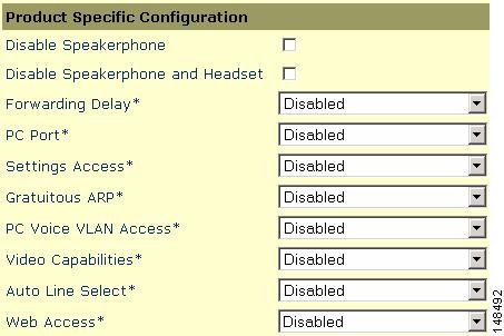
Cisco Unified IP Phones contain built-in features to increase security on a IP Telephony network. These features can be enabled or disabled on a phone-by-phone basis to increase the security of an IP Telephony deployment. Depending on the placement of the phones, a security policy will help determine if these features need to be enabled and where they should be enabled. (See Figure 20-2.)
Figure 20-2 Security at the Phone Level
Before attempting to configure the security features on a phone, check the documentation at the following link to make sure the features are available on that particular phone model:
PC Port on the Phone
The phone has the ability to turn on or turn off the port on the back of the phone, to which a PC would normally be connected. This feature can be used as a control point to access the network if that type of control is necessary.
Depending on the security policy and placement of the phones, the PC port on the back of any given phone might have to be disabled. Disabling this port would prevent a device from plugging into the back of the phone and getting network access through the phone itself. A phone in a common area such as a lobby would typically have its port disabled. Most companies would not want someone to get into the network on a non-controlled port because physical security is very weak in a lobby. Phones in a normal work area might also have their ports disabled if the security policy requires that no device should ever get access to the network through a phone PC port. Depending on the model of phone deployed, Cisco Unified CallManager can disable the PC port on the back of the phone. Before attempting to enable this feature, check the documentation at the following link to verify that this features is supported on your particular model of Cisco Unified IP Phone:
http://www.cisco.com/en/US/products/hw/phones/ps379/tsd_products_support_series_home.html
Advantages
Disabling the phone PC port allows for phones to be placed in areas where network access from the phone should not be allowed. It controls access to the network that otherwise would be there if the PC port on the back of the phone was enabled.
Disadvantages
For each person who needs to have network access and is approved for access, a separate Ethernet port would be required to provide that person with network access if the PC port on the phone is disabled. A person could still unplug the ethernet jack from the phone and attempt to plug it into another device.
For Cisco Unified Video Advantage to operate properly, the PC port and Video Capabilities must both be enabled. The other settings can safely be disabled.
Gratuitous ARP
Just like any other data device on the network, the phones are vulnerable to traditional data attacks. The phones have features to prevent some of the common data attacks that can occur on a corporate network. One such feature is Gratuitous APR (Gratuitous Address Resolution Protocol, or GARP). This feature helps to prevent man-in-the-middle (MITM) attacks to the phone. A MITM attack involves an attacker who tricks an end station into believing that he is the router and tricks the router into believing that he is the end station. This scheme makes all the traffic between the router and the end station travel through the attacker, thus enabling the attacker to log all of the traffic or inject new traffic into the data conversation.
Gratuitous ARP helps protect the phones from having an attacker capture the signaling and RTP voice streams from the phone if the attacker was able to get onto the voice segment of the network. This feature protects only the phones; it does not protect the rest of the infrastructure from a Gratuitous ARP attack. This feature is of less importance if you are running a Cisco infrastructure because the switch port provides features that protect both the phones and the network gear. For a description of these switch port features see the section on Switch Port.
Advantages
The Gratuitous ARP feature protects the phone from a traditional MITM attack on the signaling and RTP voice streams that are sourced from the phone to the network.
Disadvantages
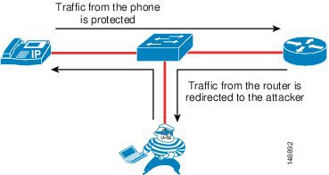
The downstream signaling and RTP voice streams coming from another phone or coming across the network are not protected by this feature in the phone. Only the data coming from the phone that has this feature enabled is protected. (See Figure 20-3.)
If the default gateway is running Hot Standby Router Protocol (HSRP), if the HSRP configuration uses the burned-in MAC address rather than the virtual MAC address for the default gateway, and if the primary router fails-over to a secondary router that has a new MAC address, the phones could maintain the old MAC address of the default gateway. This scenario could cause an outage for up to 40 minutes. Always use the virtual MAC address in an HSRP environment to avoid this potential problem.
Figure 20-3 Gratuitous ARP Protects the Phone that Has It but Not Other Traffic
As shown in Figure 20-3, the traffic from the phone that has Gratuitous ARP is protected, but the attacker could still see the traffic coming from another endpoint because that endpoint might not have the ability to protect the data flow.
PC Voice VLAN Access
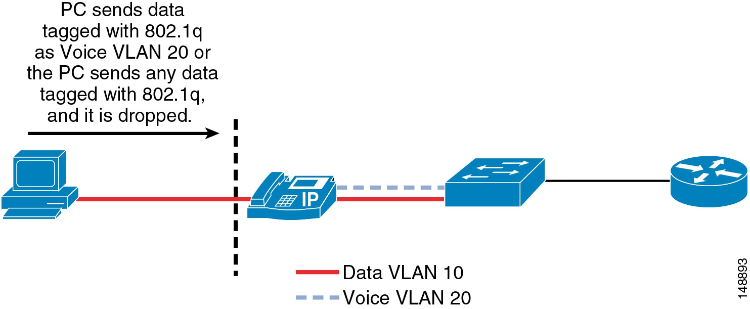
Because there are two VLANs from the switch to the phone, the phone needs to protect the voice VLAN from any unwanted access. The phones can prevent unwanted access into the voice VLAN from the back of the phone. A feature call PC Voice VLAN Access prevents any access to the voice VLAN from the PC port on the back of the phone. When disabled, this feature does not allow the devices plugged into the PC port on the phone to "jump" VLANs and get onto the voice VLAN by sending 802.1q tagged information destined for the voice VLAN to the PC port on the back of the phone. The feature operates one of two ways, depending on the phone that is being configured. On the more advanced phones, the phone will block any traffic destined for the voice VLAN that is sent into the PC port on the back of the phone. In the example shown in Figure 20-4, if the PC tries to send any voice VLAN traffic (with an 802.1q tag of 200 in this case) to the PC port on the phone, that traffic will be blocked. The other way this feature can operate is to block all traffic with an 802.1q tag (not just voice VLAN traffic) that comes into the PC port on the phone.
Currently, 802.1q tagging from an access port is not normally used. If that feature is a requirement for the PC plugged into the port on the phone, you should use a phone that allows 802.1q tagged packets to pass through the phone.
Before attempting to configure the PC Voice VLAN Access feature on a phone, check the documentation at the following link to make sure the feature is available on that particular phone model:
http://www.cisco.com/en/US/products/hw/phones/ps379/tsd_products_support_series_home.html
Figure 20-4 Blocking Traffic to the Voice VLAN from the Phone PC Port
Advantages
The PC Voice VLAN Access feature prevents attackers from sending uncontrolled data into the voice VLAN through the PC port on the back of the phone.
Disadvantages
If the device plugged into the phone is normally allowed to send 802.1q tagged packets, then these packets will be dropped. Most end stations are not allowed to perform this function at the access layer. If that function is considered normal operation within a network, this feature would not allow that function to work.
Web Access
Each Cisco Unified IP Phone has a web server built into it to help with debugging and remote status of the phone for management purposes. The web server also enables the phones to receive applications pushed from Cisco Unified CallManager to the phones. Access to this web server can be enabled or disabled on a phone by means of the Web Access feature in the Cisco Unified CallManager configuration. This setting can be global, or it could be enabled or disabled on a phone-by-phone basis.
Advantages
With Web Access enabled on the phones, the phones can be used to assist in debugging issues with a phone or within the network. If Web Access from the phone is disabled, users or an attacker cannot get information from the phone about the IP Telephony network.
Disadvantages
If Web Access from the phone is disabled, debugging network or IP Telephony issues can be more difficult. If the web server is globally disable but it is needed to help with debugging, then the administrator for Cisco Unified CallManager will have to enable this feature on the phones. The ability to get to this web page can be controlled by an ACL in the network, leaving network operators with the capability to get to the web page when needed.
With the Web Access feature disabled, the phones will be unable to receive applications pushed to them from Cisco Unified CallManager.
Video Capabilities
For Cisco Unified Video Advantage to operate properly, the PC port and Video Capabilities must both be enabled. The other settings can safely be disabled. The Device Security Mode operates as specified, even when Cisco Unified Video Advantage is in use, but Cisco Unified Video Advantage itself does not support authentication or encryption of the Cisco Audio Session Tunnel (CAST) protocol or its RTP media traffic. When an IP Phone is in Authenticated mode, the Skinny Client Control Protocol (SCCP) signaling between the phone and Cisco Unified CallManager will be authenticated, but the CAST signaling between the phone and Cisco Unified Video Advantage will not be authenticated. Likewise, when a phone is in Encrypted mode, the audio stream between the phones will be encrypted, but the video streams between the Cisco Unified Video Advantage clients will not be encrypted. Users should be notified that the video channel is not encrypted even though an icon on the phone appears to indicate that they are in an encrypted call.
Advantages
The PC port and Video Capabilities are required for Cisco Unified Video Advantage to function correctly.
Disadvantages
Enabling these features could possibly allow communication to the phone from the PC if ACLs are not used to protect the phone.
Settings Access
Each Cisco Unified IP Phone has a network settings page that lists many of the network elements and detailed information that is needed for the phone to operate. This information could be used by an attacker to start a reconnaissance on the network with some of the information that is displayed on the phone's web page. For example, an attacker could look at the settings page to determine the default gateway, the TFTP server, and the Cisco Unified CallManager IP address. Each of these pieces of information could be used to gain access to the voice network or to attack a device in the voice network.
This access can be disabled on a phone-by-phone basis (see Figure 20-5) to prevent end users or attackers from obtaining the additional information such as Cisco Unified CallManager IP address and TFTP server information.
For more information on the phone settings page, refer to Cisco Unified IP Phone Authentication and Encryption for Cisco Unified CallManager, available at
Figure 20-5 Phone Configuration Page in Cisco Unified CallManager
Advantages
With access to the phone settings page disabled, end users and potential attackers are not able to see detailed information about the network and the IP Telephony information used by the voice system. With this feature disabled, some of the information that would be protected includes the IP address of the phone and the Cisco Unified CallManager to which the phone is registered.
Disadvantages
With access to the phone settings page disabled, end users lose the ability to change many of the settings on the phone that they would normally be able to control, such as speaker volume, contrast, and ring type. It might not be practical to use this security feature because of the limitations it places on end users with respect to the phone interface. However, access to the phone settings page does not have to be lost if the administrator chooses to restrict access rather than disable it.
Phone Authentication and Encryption
Cisco Unified CallManager can be configured to provide multiple levels of security to the phones within a voice system, if those phones support those features. Depending on your security policy, phone placement, and phone support, the security can be configured to fit the needs of your company.
For information on which Cisco Unified IP Phone models support specific security features, refer to the documentation available at
http://www.cisco.com/en/US/products/hw/phones/ps379/tsd_products_support_series_home.html
To enable security on the phones and in the Cisco Unified CallManager cluster, refer to the Cisco Unified CallManager Security Guide, available at
http://www.cisco.com/en/US/products/sw/voicesw/ps556/prod_maintenance_guides_list.html
Advantages
When the security features are properly configured in Cisco Unified CallManager, all supported phones will have the following capabilities:
•
•
•
•
Disadvantages
Cisco Unified CallManager supports authentication, integrity, and encryption for calls between two Cisco Unified IP Phones within a single cluster where no media services are used. However, Cisco Unified CallManager does not provide authentication, integrity, or encryption for all devices or phones. To determine if your device supports these features, refer to the documentation available at
http://www.cisco.com/en/US/products/hw/phones/ps379/tsd_products_support_series_home.html
In addition, auto-registration does not work if you configure the cluster for mixed mode, which is required for device authentication. You cannot implement signaling or media encryption if device authentication does not exist in the cluster - that is, if you do not install and configure the Cisco Certificate Trust List (CTL) client. Application Layer Gateways (ALGs) that allow IP Telephony traffic to traverse firewalls and Network Address Translation (NAT) also do not work with signaling encryption. Not all gateways, phones, or conference are supported with encrypted media.
Access Security
This section covers security features at the Access level that can be used to protect the voice data within a network.
Voice and Video VLANs
Before the phone has its IP address, the phone determines which VLAN it should be in by means of the Cisco Discovery Protocol (CDP) negotiation that takes place between the phone and the switch. This negotiation allows the phone to send packets with 802.1q tags to the switch in a "voice VLAN" so that the voice data and all other data coming from the PC behind the phone are separated from each other at Layer 2. Voice VLANs are not required for the phones to operate, but they provide additional separation from other data on the network.
Cisco Unified Video Advantage is a client application running on a PC, but it is also associated with an IP Phone. The PC will likely reside in the data VLAN while the phone will likely reside in the voice VLAN. To associate with the IP Phone, Cisco Unified Video Advantage uses the Cisco Audio Session Tunnel (CAST) protocol, which operates over TCP/IP. Therefore, Cisco Unified Video Advantage will have to communicate through whatever Layer 3 router is configured to route IP packets between the voice and data VLANs. If there are any access control lists or firewalls configured between those VLANs, they will have to be modified to permit the CAST protocol to operate. Fortunately, CAST uses TCP port 4224 in both directions, making this task easier. Cisco Unified Video Advantage communicates with the IP Phone but not with Cisco Unified CallManager, except when Cisco Unified Video Advantage periodically checks with the TFTP server (which could be co-resident on one or more of the Cisco Unified CallManager servers) to download any software updates. Therefore, you must also permit the TFTP protocol between the data VLAN and the TFTP server(s).
Sony and Tandberg SCCP endpoints do not support Cisco Discovery Protocol (CDP) or 802.1Q VLAN ID tagging. Therefore, in a typical environment, these devices will reside in the data VLAN, unless the port has been configured manually to use the voice VLAN as the native VLAN. The Sony and Tandberg endpoints communicate with the TFTP server to download their configurations, with Cisco Unified CallManager for SCCP signaling, and with other endpoints for RTP audio/video media channels. Therefore, the TFTP protocol must be permitted between the data VLAN and the TFTP server(s), TCP port 2000 must be permitted between the data VLAN and the Cisco Unified CallManager server(s), and UDP ports for RTP media must be permitted between the data and voice VLANs.
H.323 clients, Multipoint Control Units (MCUs), and gateways communicate with Cisco Unified CallManager using the H.323 protocol. Cisco Unified CallManager H.323 trunks (such as H.225 and intercluster trunk variants as well as the RASAggregator trunk type) use a random port range rather than the well-known TCP port 1720. Therefore, you must permit a wide range of TCP ports between these devices and the Cisco Unified CallManager servers. MCUs and gateways are considered infrastructure devices, and they typically reside within the datacenter adjacent to the Cisco Unified CallManager servers. H.323 clients, on the other hand, typically reside in the data VLAN.
Cisco Unified Videoconferencing 3500 Series MCUs configured to run in SCCP mode communicate with the TFTP server(s) to download their configuration, with the Cisco Unified CallManager servers for signaling, and with other endpoints for RTP media traffic. Therefore, TFTP must be permitted between the MCU and the TFTP server(s), TCP port 2000 must be permitted between the MCUs and the Cisco Unified CallManager server(s), and UDP ports for RTP media must be permitted between the MCUs and the voice, data, and gateway VLANs
Advantages
Voice VLANs can be assigned automatically from the switch to the phone, thus allowing for Layer 2 and Layer 3 separations between voice data and all other data on a network. A voice VLAN also allows for a different IP addressing scheme because the separate VLAN can have a separate IP scope at the Dynamic Host Configuration Protocol (DHCP) server.
Applications use the CDP messaging from the phones to assist in locating phones during an emergency phone call. The location of the phone will be much more difficult to determine if CDP is not enabled on the access port to which that phone is attached.
Disadvantages
There is a possibility that information could be gathered from the CDP messaging that would normally go to the phone, and that information could be used to discover some of the network. Not all devices that can be used for voice or video with Cisco Callmanager are able to use CDP to assist in discovering the voice VLAN.
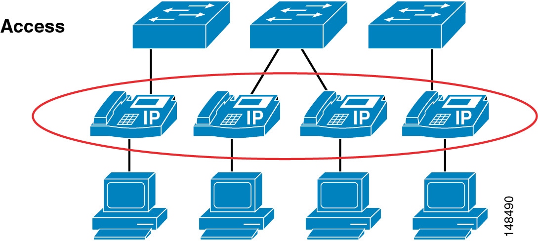
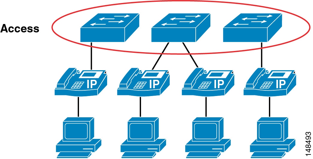
Switch Port
There are many security features within a Cisco switch infrastructure that can be used to secure a data network. This section describes some of the features that can be used in Cisco Access Switches to protect the IP Telephony data within a network. (See Figure 20-6.) This section does not cover all of the security features available for all of the current Cisco switches, but it does list the most common security feature used across many of the switches that Cisco manufactures. For additional information on the security features available on the particular Cisco gear deployed within your network, refer to the appropriate product documentation available at
Figure 20-6 A Typical Access Layer Design to Which the Phones Attach
Port Security: MAC CAM Flooding
A classic attack on a switched network is a MAC content-addressable memory (CAM) flooding attack. This type of attack floods the switch with so many MAC addresses that the switch does not know which port an end station or device is attached to. When the switch does not know which port a device is attached to, it broadcasts the traffic destined for that device to the entire VLAN. In this way, the attacker is able to see all traffic that is coming to all the users in a VLAN.
To disallow malicious MAC flooding attacks from hacker tools such as macof, limit the number of MAC addresses allowed to access individual ports based on the connectivity requirements for those ports. Malicious end-user stations can use macof to originate MAC flooding from random-source to random-destination MAC addresses, both directly connected to the switchport or through the IP phone. The macof tool is very aggressive and typically can fill a Cisco Catalyst switch content-addressable memory (CAM) table in less than ten seconds. The flooding of subsequent packets that remain unlearned because the CAM table is filled, is as disruptive and unsecure as packets on a shared Ethernet hub for the VLAN that is being attacked.
Either port security or dynamic port security can be used to inhibit a MAC flooding attack. A customer with no requirement to use port security as an authorization mechanism would want to use dynamic port security with the number of MAC addresses appropriate to the function attached to a particular port. For example, a port with only a workstation attached to it would want to limit the number of learned MAC addresses to one. A port with a Cisco Unified IP Phone and a workstation behind it would want to set the number of learned MAC addresses to two (one for the IP phone itself and one for the workstation behind the phone) if a workstation is going to plug into the PC port on the phone. This setting in the past has been three MAC addresses, used with the older way of configuring the port in trunk mode. If you use the multi-VLAN access mode of configuration for the phone port, this setting will be two MAC addresses, one for the phone and one for the PC plugged into the phone. If there will be no workstation on the PC port, then the number of MAC addresses on that port should be set to one. These configurations are for a multi-VLAN access port on a switch. The configuration could be different if the port is set to trunk mode (not the recommended deployment of an access port with a phone and PC).
Port Security: Prevent Port Access
Prevent all port access except from those devices designated by their MAC addresses to be on the port. This is a form of device-level security authorization. This requirement is used to authorize access to the network by using the single credential of the device's MAC address. By using port security (in its non-dynamic form), a network administrator would be required to associate MAC addresses statically for every port. However, with dynamic port security, network administrators can merely specify the number of MAC addresses they would like the switch to learn and, assuming the correct devices are the first devices to connect to the port, allow only those devices access to that port for some period of time.
The period of time can be determined by either a fixed timer or an inactivity timer (non-persistent access), or it can be permanently assigned. The feature to permanently assign a MAC address on a Cisco 6000 switch it is call autoconfigure, and on the Cisco 4500, 2550, 2750, or 2950 switches the feature is called sticky. In both cases, the MAC address learned will remain on the port even in the event of a reload or reboot of the switch.
Persistent assignment of MAC addresses via autoconfigure or sticky can be cleared only by a command. The most common default behavior seen across the Cisco Catalyst switching platforms currently is the non-persistent behavior; the only behavior prior to Cisco CatOS Release 7.6(1) was persistent. No provision is made for device mobility by static port security or persistent dynamic port security. Although it is not the primary requirement, MAC flooding attacks are implicitly prevented by port security configurations that aim to limit access to certain MAC addresses.
From a security perspective, there are better mechanisms for both authenticating and authorizing port access based on userid and/or password credentials rather than using MAC address authorization. MAC addresses alone can easily be spoofed or falsified by most operating systems.
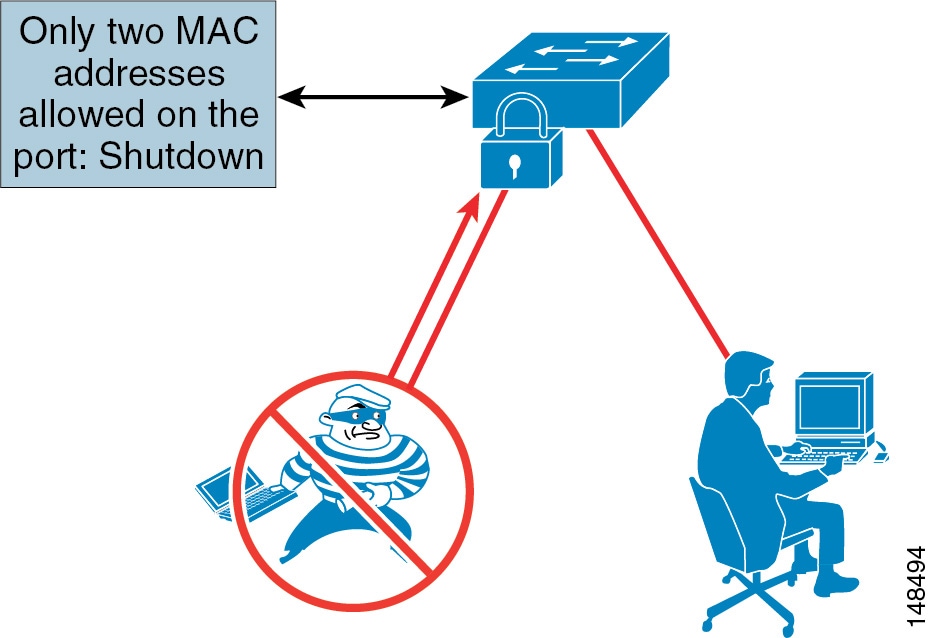
Port Security: Prevent Rogue Network Extensions
Prevent rogue network extensions via hub or wireless access points (APs). Because it limits the number of MAC addresses to a port, port security can also be used as a mechanism to inhibit user extension to the IT-created network. For example, if a user plugs a wireless AP into a user-facing port or data port on a phone with port security defined for a single MAC address, the wireless AP itself would occupy that MAC address and not allow any devices behind it to access the network. (See Figure 20-7.) Generally, a configuration appropriate to stop MAC flooding is also appropriate to inhibit rogue access.
Figure 20-7 Limited Number of MAC Addresses Prevents Rogue Network Extensions
Advantages
Port security prevents an attacker from flooding the CAM table of a switch and from turning any VLAN into a hub that transmits all received traffic to all ports. It also prevents unapproved extensions of the network by adding hubs or switches into the network.
Disadvantages
If the number of MAC addresses is not defined correctly, there is a possibility of denying access to the network or error-disabling the port and removing all devices from the network.
Configuration Example
Note
The following example illustrates the Cisco IOS commands to configure an access port with dynamic port security, running a phone with a device plugged into the data port on the phone:
switchport access vlan 10switchport mode accessswitchport voice vlan 20switchport port-securityswitchport port-security maximum 2switchport port-security violation restrictswitchport port-security aging time 2switchport port-security aging type inactivityThe commands in the preceding example perform the following functions:
•
This command enables the port security on the specified module/port.
•
This command is the recommended configuration. The default is to disable the port. If you restrict the port, it will learn up to the maximum number of MAC addresses and then stop learning any new MAC addresses. If you have the port on the default setting of disable and the maximum number of MAC addresses is exceeded, the port will error-disable and turn off power to the phone. The default timer for the port to re-enable is 5 minutes. Depending on your security policy, it might be preferable to restrict the port and not shut down the phone by disabling the port.
•
This command sets the amount of time that the MAC address will remain on the port without any traffic from that MAC address. Because of CDP communication between some switches and the phone, the recommended minimum time is 2 minutes.
•
This command defines the type of aging that will be used on the port to time-out the learned MAC address.
DHCP Snooping: Prevent Rogue DHCP Server Attacks
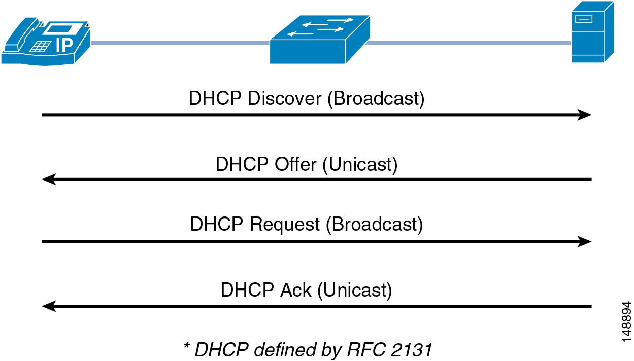
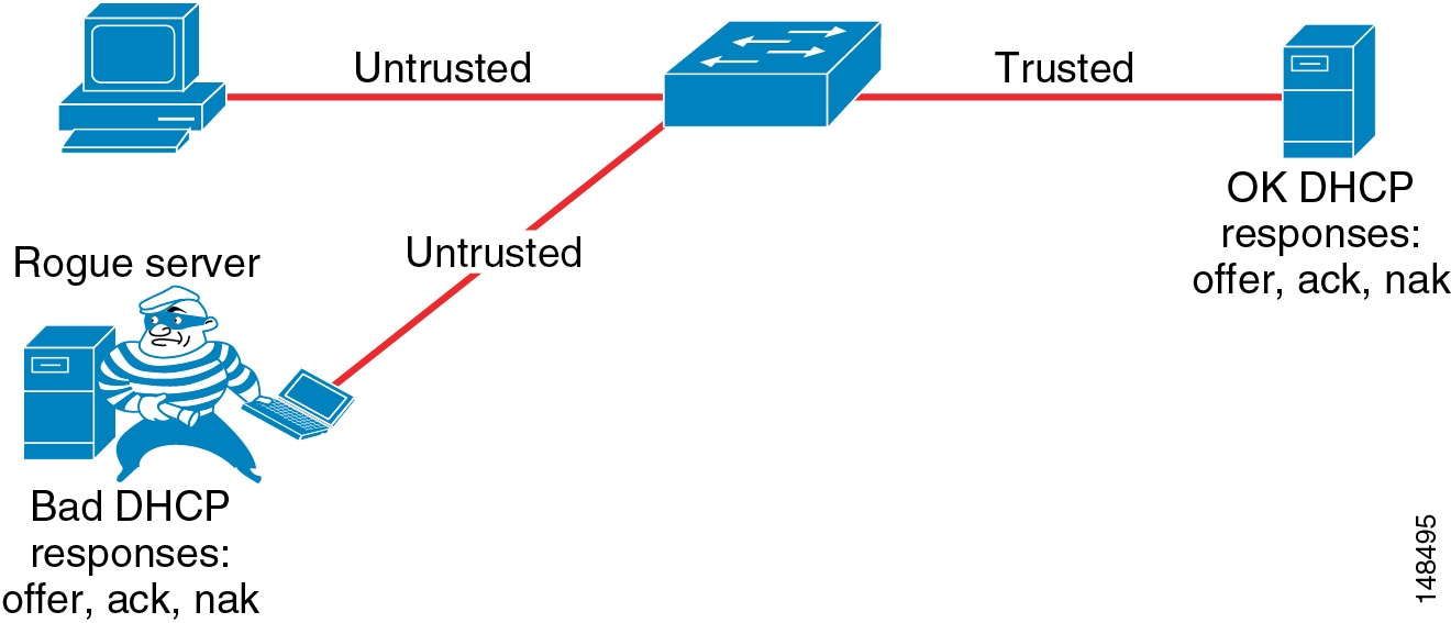
Dynamic Host Configuration Protocol (DHCP) Snooping prevents a non-approved DHCP or rouge DHCP server from handing out IP addresses on a network by blocking all replies to a DHCP request unless that port is allowed to reply. Because most phone deployments use DHCP to provide IP addresses to the phones, you should use the DHCP Snooping feature in the switches to secure DHCP messaging. Rouge DHCP servers can attempt to respond to the broadcast messages from a client to give out incorrect IP addresses, or they can attempt to confuse the client that is requesting an address.
When enabled, DHCP Snooping treats all ports in a VLAN as untrusted by default. An untrusted port is a user-facing port that should never make any reserved DHCP responses. If an untrusted DHCP-snooping port makes a DHCP server response, it will be blocked from responding. Therefore, rogue DHCP servers will be prevented from responding. However, legitimately attached DHCP servers or uplinks to legitimate servers must be trusted.
Figure 20-8 illustrates the normal operation of a network-attached device that requests an IP address from the DHCP server.
Figure 20-8 Normal Operation of a DHCP Request
However, an attacker can request not just a single IP address but all of the IP addresses that are available within a VLAN. (See Figure 20-9.) This means that there would be no addresses for a legitimate device trying to get on the network, and without an IP address the phone cannot connect to Cisco Unified CallManager.
Figure 20-9 An Attacker Can Take All Available IP Addresses on the VLAN
Advantaged
DHCP Snooping prevents unapproved DHCP servers from being on a network.
Disadvantages
Incorrect configurations of this feature can deny IP addresses to approved users.
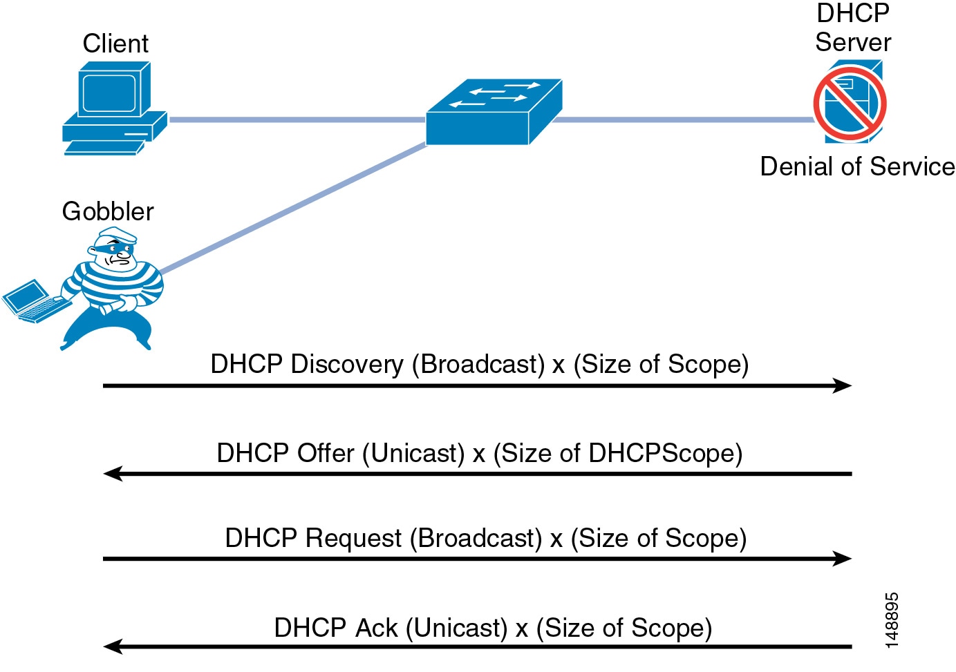
DHCP Snooping: Prevent DHCP Starvation Attacks
DHCP address scope starvation attacks from tools such as Gobbler are used to create a DHCP denial-of-service (DoS) attack. Because the Gobbler tool makes DHCP requests from different random source MAC addresses, you can prevent it from starving a DHCP address space by using port security to limit the number of MAC addresses. (See Figure 20-10.) However, a more sophisticated DHCP starvation tool can make the DHCP requests from a single source MAC address and vary the DHCP payload information. With DHCP Snooping enabled, untrusted ports will make a comparison of the source MAC address to the DHCP payload information and fail the request if they do not match.
Figure 20-10 Using DHCP Snooping to Prevent DHCP Starvation Attacks
Advantages
DHCP Snooping prevents any single device from capturing all the IP addresses in any given scope.
Disadvantages
Incorrect configurations of this feature can deny IP addresses to approved users.
Configuration Example
The following example illustrates the Cisco IOS commands to configure an access port with DHCP Snooping, running a phone with a device plugged into the data port on the phone:
•
ip dhcp snooping vlan 10, 20no ip dhcp snooping information optionip dhcp snooping•
no ip dhcp snooping trust (Default)ip dhcp snooping limit rate 10 (pps)ip dhcp snooping trustThe global commands in the preceding example perform the following functions:
•
This command specifies which VLANs have DHCP Snooping enabled.
•
This command should be used so that Option 82 information is not required to lease a DHCP address. The Option 82 information must be supported by the DHCP server, but most enterprise servers do not support this feature. Option 82 is supported in Cisco IOS DHCP servers.
•
This command enables DHCP Snooping at the global level on the switches.
The interface commands in the preceding example perform the following functions:
•
This command sets the interface to not trust any information coming into the port from a DHCP server.
•
This command sets the default rate limit that is configured on the interface when DHCP Snooping is initially configured. This value can be changed depending on your security policy.
•
You must use this command on the port through which DHCP information will be sent from a DHCP server. If you do not trust the port from which the DHCP information is coming, then none of the devices will ever receive a DHCP address. At least one port (access port or trunk port) with the DHCP server on it must be configured to allow this information to get to the clients. This command can also be used to trust any device connected to a port that has a static IP address and that will not use DHCP to get an IP address. Note that the uplink port to the DHCP server, or the trunk port to the DHCP server, will also have to be trusted.
DHCP Snooping: Binding Information
Another function of DHCP Snooping is to record the DHCP binding information for untrusted ports that successfully get IP addresses from the DHCP servers. The binding information is recorded in a table on the Cisco Catalyst switch. The DHCP binding table contains the IP address, MAC address, lease length, port, and VLAN information for each binding entry. The binding information from DHCP Snooping remains in effect for the length of the DHCP binding period set by the DHCP server (that is, the DHCP lease time). The DHCP binding information is used to create dynamic entries for Dynamic ARP Inspection (DAI) to limit ARP responses for only those addresses that are DHCP-bound. The DHCP binding information is also used by the IP source guard to limit sourcing of IP packets to only those addresses that are DHCP-bound.
The following examples show binding information from DHCP Snooping.
•
show ip dhcp snooping bindingMacAddress IpAddress Lease(sec) Type VLAN Interface---------- --------- ---------- ------------- ---- ---------00:03:47:B5:9F:AD 10.120.4.10 193185 dhcp-snooping 10 FastEthernet3/18•
ngcs-6500-1> (enable) show dhcp-snooping bindingsMacAddress IpAddress Lease(sec) VLAN Port------------------ --------------- ---------- ---- -----00-10-a4-92-bf-dd 10.10.10.21 41303 10 2/5There is a maximum limit to the number of binding table entries that each type of switch can store for DHCP Snooping. (Refer to the product documentation for your switch to determine this limit.) If you are concerned about the number of entries in your switch's binding table, you can reduce the lease time on the DHCP scope so that the entries in the binding table time-out sooner. The entries remain in the DHCP binding table until the lease runs out. In other words, the entries remain in the DHCP Snooping binding table as long at the DHCP server thinks the end station has that address. They are not removed from the port when the workstation or phone is unplugged.
If you have a Cisco Unified IP Phone plugged into a port and then move it to a different port, you might have two entries in the DHCP binding table with the same MAC and IP address on different ports. This behavior is considered normal operation.
Requirement for Dynamic ARP Inspection
Dynamic Address Resolution Protocol (ARP) Inspection (DAI) is a feature used on the switch to prevent Gratuitous ARP attacks on the devices plugged into the switch and on the router. Although it is similar to the Gratuitous ARP feature mentioned previously for the phones, Dynamic ARP protects all the devices on the LAN, and it is not just a phone feature.
In its most basic function, Address Resolution Protocol (ARP) enables a station to bind a MAC address to an IP address in an ARP cache, so that the two stations can communicate on a LAN segment. A station sends out an ARP request as a MAC broadcast. The station that owns the IP address in that request will give an ARP response (with its IP and MAC address) to the requesting station. The requesting station will cache the response in its ARP cache, which has a limited lifetime. The default ARP cache lifetime for Microsoft Windows is 2 minutes; for Linux, the default lifetime is 30 seconds; and for Cisco IP phones, the default lifetime is 40 minutes.
ARP also makes the provision for a function called Gratuitous ARP. Gratuitous ARP (GARP) is an unsolicited ARP reply. In its normal usage, it is sent as a MAC broadcast. All stations on a LAN segment that receive a GARP message will cache this unsolicited ARP reply, which acknowledges the sender as the owner of the IP address contained in the GARP message. Gratuitous ARP has a legitimate use for a station that needs to take over an address for another station on failure.
However, Gratuitous ARP can also be exploited by malicious programs that want to illegitimately take on the identity of another station. When a malicious station redirects traffic to itself from two other stations that were talking to each other, the hacker who sent the GARP messages becomes the man-in-the-middle. Hacker programs such as ettercap do this with precision by issuing "private" GARP messages to specific MAC addresses rather than broadcasting them. In this way, the victim of the attack does not see the GARP packet for its own address. Ettercap also keeps its ARP poisoning in effect by repeatedly sending the private GARP messages every 30 seconds.
Dynamic ARP Inspection (DAI) is used to inspect all ARP requests and replies (gratuitous or non-gratuitous) coming from untrusted (or user-facing) ports to ensure that they belong to the ARP owner. The ARP owner is the port that has a DHCP binding which matches the IP address contained in the ARP reply. ARP packets from a DAI trusted port are not inspected and are bridged to their respective VLANs.
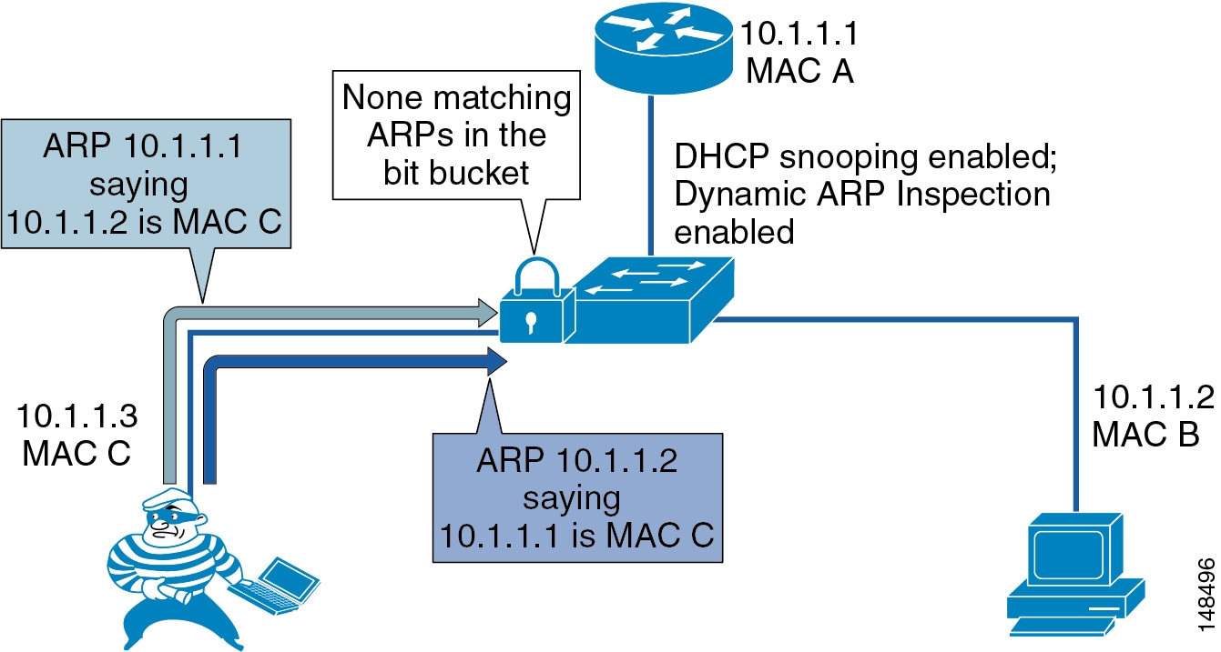
Using DAI
Dynamic ARP Inspection (DAI) requires that a DHCP binding be present to legitimize ARP responses or Gratuitous ARP messages. If a host does not use DHCP to obtain its address, it must either be trusted or an ARP inspection access control list (ACL) must be created to map the host's IP and MAC address. (See Figure 20-11.) Like DHCP Snooping, DAI is enabled per VLAN, with all ports defined as untrusted by default. To leverage the binding information from DHCP Snooping, DAI requires that DHCP Snooping be enabled on the VLAN prior to enabling DAI. If DHCP Snooping is not enabled before you enable DAI, none of the devices in that VLAN will be able to use ARP to connect to any other device in their VLAN, including the default gateway. The result will be a self-imposed denial of service to any device in that VLAN.
Figure 20-11 Using DHCP Snooping and DAI to Block ARP Attacks
Because of the importance of the DHCP Snooping binding table to the use of DAI, it is important to back up the binding table. The DHCP Snooping binding table can be backed up to bootflash, File Transfer Protocol (FTP), Remote Copy Protocol (RCP), slot0, and Trivial File Transfer Protocol (TFTP). If the DHCP Snooping binding table is not backed up, the Cisco Unified IP Phones could lose contact with the default gateway during a switch reboot. For example, assume that the DHCP Snooping binding table is not backed up and that you are using Cisco Unified IP Phones with a power adapter instead of line power. When the switch comes back up after a reboot, there will be no DHCP Snooping binding table entry for the phone, and the phone will not be able to communicate with the default gateway unless the DHCP Snooping binding table is backed up and loads the old information before traffic starts to flow from the phone.
Advantages
DAI prevents an attacker from running ARP-based attacks in a network to disrupt or sniff the traffic between people who are adjacent to the attacker at Layer 2.
Disadvantages
Incorrect configurations of this feature can deny network access to approved users. If a device has no entry in the DHCP Snooping binding table, then that device will not be able to use ARP to connect to the default gateway and therefore will not be able to send traffic. If you use static IP addresses, those addresses will have to be entered manually into the DHCP Snooping binding table. If you have devices that do not use DHCP again to obtain their IP addresses when a link goes down (some UNIX or Linux machines behave this way), then you must back up the DHCP Snooping binding table.
Configuration Example
The following example illustrates the Cisco IOS commands to configure access ports with DHCP Snooping and Dynamic ARP Inspection:
•
ip dhcp snooping vlan 10,20 (required)no ip dhcp snooping information option (required without option 82 dhcp server)ip dhcp snooping (required)ip arp inspection vlan 10,20ip dhcp snooping database tftp://172.26.168.10/tftpboot/cisco/ngcs-dhcpdb•
ip dhcp snooping trustip arp inspection trustno ip arp inspection trust (default)ip arp inspection limit rate 15 (pps)The global commands in the preceding example perform the following functions:
•
This command specifies which VLANs have Dynamic ARP Inspection (DAI) enabled.
•
As with ip dhcp snooping trust, this command allows a trusted device such as a router to reply to ARP messages. This command must be configured on the port for your router, otherwise the router will not be able to respond to any ARP requests because the router will not be in the DHCP Snooping binding table.
•
This is the default setting for every port in the VLAN. Trust must be enabled.
•
This command sets the global default value for the maximum number of packets per second (pps) that are allow for ARP messages on the interfaces. If this value is exceeded, then the interface will be disabled. If this behavior is a concern, you can increase or decrease the limit or set it to none.
•
This command backs up the DHCP Snooping binding table to the TFTP server. The DHCP Snooping binding table can be backed up to bootflash, FTP, RCP, slot0, and TFTP.
The interface commands in the preceding example perform the following functions:
•
This command enables DAI on the port and checks all ARPs against the DHCP Snooping binding table.
•
This command specifies the maximum number of packets per second (pps) that are allow for ARP messages on the interface. If the interface sees more than the specified number of ARP messages in a second, it will disable the port. Depending on your security policy, the default value (15 pps) might be the preferred setting. If you do not want to disable the phone when the port receives more then 15 ARP messages in a second, you can set the rate limit to none, which will allow the phone to stay up.
IP Source Guard
Beyond ARP spoofing, an attacker can also do IP address spoofing. This method is commonly use to perform DoS attacks on a second party by sending packets through a third party, thus masking the identity of the attacking system. A simple example of this occurs when an attacker pings a third-party system while sourcing the IP address of the second party that is being attacked. The ping response will be directed to the second party from the third-party system. Aggressive SYN-flooding originating from spoofed IP addresses is another common type of attack used to overwhelm a server with TCP half-sessions.
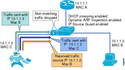
The IP Source Guard (IPSG) feature, when invoked, dynamically creates an ACL based on the contents of the DHCP Snooping binding table. This ACL ensures that traffic is sourced from the IP address issued at DHCP binding time and prevents any traffic from being forwarded by other spoofed addresses. While DHCP Snooping is a prerequisite for IP Source Guard, DAI is not. However, Cisco recommend that you enable DAI in addition to IP Source Guard to prevent ARP-poisoning man-in-the-middle attacks in addition to IP address spoofing. (See Figure 20-12.)
Figure 20-12 Using IP Source Guard to Prevent Address Spoofing
With IP address spoofing, an attacker can impersonate a valid address either by manually changing an address or by running a program design to do address spoofing, such as hping2. Internet worms can use spoofing techniques to disguise their origins.
Configuration Example
The following example illustrates the Cisco IOS commands to configure access ports with IP Source Guard:
•
ip dhcp snooping vlan 4,104no ip dhcp snooping information optionip dhcp snooping•
ip verify source vlan dhcp-snoopingAdditional Information
For additional information on network security, refer to the Cisco documentation at the following locations:
•
Quality of Service
Quality of Service (QoS) is a vital part of any security policy for an enterprise network. Even though most people think of QoS as setting the priority of traffic in a network, it also controls the amount of data that is allowed into the network. In the case of Cisco switches, that control point is at the port level when the data comes from the phone to the Ethernet switch. The more control applied at the edge of the network at the access port, the fewer problems will be encountered as the data aggregates in the network.
As mentioned previously in the lobby phone example, you can provide enough flow control of the traffic at the access port level to prevent any attacker from launching a denial-of-service (DoS) attack from that port in the lobby. The configuration for that example was not as aggressive as it could be because the QoS configuration allowed traffic sent to the port to exceed the maximum rate, but the traffic was remarked to the level of scavenger class. Given a more aggressive QoS policy, any amount of traffic that exceeded that maximum limit of the policy could just be dropped at the port, and that "unknown" traffic would never make it into the network. QoS should be enabled across the entire network to give the IP Telephony data high priority from end to end.
For more information on QoS, refer to the chapter on Network Infrastructure, page 3-1, and the Enterprise QoS Solution Reference Network Design (SRND) Guide available at
Advantages
QoS can be used to control not only the priority of the traffic in the network but also the amount of traffic that can travel through any specific interface. Cisco Smartports templates have been created to assist in deploying voice QoS in a network at the access port level.
Disadvantages
If QoS settings are outside the standard Cisco Smartports template, the configuration can be complex and difficult to manage in large IP Telephony deployments.
Access Control Lists
This section covers access control lists (ACLs) and their uses in protecting voice data.
VLAN Access Control Lists
You can use VLAN access control lists (ACLs) to control data that flows on a network. Cisco switches have the capability of controlling Layers 2 to 4 within a VLAN ACL. Depending on the types of switches in a network, VLAN ACLs can be used to block traffic into and out of a particular VLAN. They can also be used to block intra-VLAN traffic to control what happens inside the VLAN between devices.
If you plan to deploy a VLAN ACL, you should verify which ports are needed to allow the phones to function with each application used in your IP Telephony network. Normally any VLAN ACL would be applied to the VLAN that the phones use. This would allow control at the access port, as close as possible to the devices that are plugged into that access port.
Refer to the following product documentation for information on configuring VLAN ACLs:
•
•
•
•
The following example represents a VLAN ACL that allows only the traffic for a Cisco 7960 IP Phone to boot and function in a VLAN. (Inline comments indicate the purpose of each line of the ACL.) This example VLAN ACL is for the ports used with Cisco Unified CallManager Release 4.1. The example uses the following IP address ranges:
•
•
•
•
•
Note
20 permit udp host 10.0.10.2 eq 1985 any30 permit udp host 10.0.10.3 eq 1985 any!permit HSRP from the routers40 permit udp any any eq bootpc50 permit udp any any eq bootps!permit DHCP activity60 permit udp 10.0.10.0 0.0.0.255 range 49152 65535 10.0.20.0 0.0.0.255 eq tftp70 permit udp 10.0.20.0 0.0.0.255 range 1024 5000 10.0.10.0 0.0.0.255 range 49152 6553580 permit udp 10.0.10.0 0.0.0.255 range 49152 65535 10.0.20.0 0.0.0.255 range 1024 5000!permit the tftp traffic from the tftp server and phone90 permit udp 10.0.10.0 0.0.0.255 range 49152 65535 host 10.0.40.3 eq domain100 permit udp host 172.19.244.2 eq domain 10.0.10.0 0.0.0.255 range 49152 65535!permit DNS to and from the phone110 permit tcp 10.0.10.0 0.0.0.255 range 49152 65535 10.0.20.0 0.0.0.255 eq 2000120 permit tcp 10.0.20.0 0.0.0.255 eq 2000 10.0.10.0 0.0.0.255 range 49152 65535!permit signaling to and from the phone.130 permit udp 10.0.10.0 0.0.0.255 range 16384 32767 10.0.10.0 0.0.0.255 range 16384 32767140 permit udp 10.0.0.0 0.0.255.255 range 16384 32767 10.0.10.0 0.0.0.255 range 16384 32767150 permit udp 10.0.10.0 0.0.0.255 range 16384 32767 10.0.0.0 0.0.255.255 range 16384 43767!permit all phones to send udp to each other160 permit tcp 10.0.10.0 0.0.0.255 range 49152 65535 10.0.20.0 0.0.0.255 eq www170 permit tcp 10.0.20.0 0.0.0.255 eq www 10.0.10.0 0.0.0.255 range 49152 65535180 permit tcp 10.0.20.0 0.0.0.255 range 49152 65535 10.0.10.0 0.0.0.255 eq www190 permit tcp 10.0.10.0 0.0.0.255 eq www 10.0.20.0 0.0.0.255 range 49152 65535!permit web access to and from the phone200 permit Intelligent Contact ManagementP any any!allow all icmp - phone to phone, gateway to phone, and NMS to phone220 permit udp 10.0.30.0 0.0.0.255 rang 16384 327676 10.0.10.0 0.0.0.255 rang 16384 32767!permit udp to the gateways in the network for pstn accessAs this example ACL illustrates, the more well-defined the IP addresses are in a network, the easier it is to write and deploy an ACL.
For more details on how to apply VLAN ACLs, refer to the following documentation:
•
•
•
•
Advantages
ACLs provide the ability to control the network traffic in and out of a VLAN as well as the ability to control the traffic within the VLAN.
Disadvantages
VLAN ACLs are very difficult to deploy and manage at an access-port level that is highly mobile. Because of these management issues, care should be taken when deploying VLAN ACLs at the access port in the network.
Router Access Control Lists
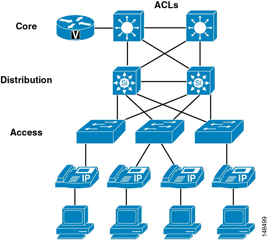
As with VLAN ACLs, routers have the ability to process both inbound and outbound ACLs by port. The first Layer 3 device is the demarcation point between voice data and other types of data when using voice and data VLANs, where the two types of data are allowed to send traffic to each other. Unlike the VLAN ACLs, router ACLs are not deployed in every access device in your network. Rather, they are applied at the edge router, where all data is prepared for routing across the network. This is the perfect location to apply a Layer 3 ACL to control which areas the devices in each of the VLANs have the ability to access within a network. Layer 3 ACLs can be deployed across your entire network to protect devices from each other at points where the traffic converges. (See Figure 20-13.)
Figure 20-13 Router ACLs at Layer 3
There are many types of ACLs that can be deployed at Layer 3. For descriptions and examples of the most common types, refer to Configuring Commonly Used IP ACLs, available (with Cisco partner login required) at
Depending on your security policy, the Layer 3 ACLs can be as simple as not allowing IP traffic from the non-voice VLANS to access the voice gateway in the network, or the ACLs can be detailed enough to control the individual ports and the time of the day that are used by other devices to communicate to IP Telephony devices. Assuming that there are no software phones, ACLs can be written to block all traffic (by IP address or IP range) to Cisco Unified CallManagers, voice gateways, phones, and any other voice application that is being used for voice-only services. This method simplifies the ACLs at Layer 3 compared to the ACLs at Layer 2 or VLAN ACLs.
This example uses the following IP address ranges:
•
•
•
•
10 deny ip 192.168.0.0 0.0.255.255 10.0.10.0 0.0.0.255!deny all non voice devices to the voip servers20 deny 192.168.0.0 0.0.255.255 10.0.30.0 0.0.0.255!deny all non voice devices to the voip gateways30 deny 192.168.0.0 0.0.255.255 10.0.20.0 0.0.0.255!deny all non voice devices to communicate with the phones ip addressesAdvantages
ACLs are much easier to manage and deploy at Layer 3. Layer 3 is one of the first opportunities to apply control to voice data and other non-voice data in the network.
Disadvantages
As the ACLs become more granular and detailed, any changes in port usage in a network could break not only voice but also other applications in the network.
If there are software phones in the network, if web access to the phone is allowed, or if you use the Attendant Console or other applications that need access to the voice VLAN subnets, the ACLs are much more difficult to deploy and control.
Gateways and Media Resources
Gateways and media resources are devices that convert an IP Telephony call into a PSTN call. When an outside call is placed, the gateway or media resource is one of the few places within an IP Telephony network to which all the voice RTP streams flow.
Because IP Telephony gateways and media resources can be placed almost anywhere in a network, securing an IP Telephony gateway or media resource might be considered more difficult than securing other devices, depending on your security policy. However, depending on which point trust is established in the network, the gateways and media resources can be quite easy to secure. Because of the way the gateways and media resources are controlled by Cisco Unified CallManager, if the path that the signaling takes to the gateway or media resource is in what is considered a secure section of the network, a simple ACL can be used to control signaling to and from the gateway or media resource. If the network is not considered secure between the gateways (or media resources) and where the Cisco Unified CallManagers are located (such as when a gateway is located at a remote branch), the infrastructure can be used to build IPSec tunnels to the gateways and media resources to protect the signaling. In most networks there would most likely be a combination of the two approaches (ACL and IPSec) to secure those devices.
For H.323 videoconferencing devices, an ACL can be written to block port 1720 for H.225 trunks from any H.323 client in the network. This method would block users from initiating an H.225 session with each other directly. Cisco devices might use different ports for H.225, so refer to the product documentation for your equipment to see which port is used. If possible, change the port to 1720 so that only one ACL is needed to control signaling.
Because we use QoS at the edge of the network, if an attacker can get into the voice VLAN and determine where the gateways and media resources are, QoS at the port would limit how much data the attacker would be able to send to the gateway or media resource. (See Figure 20-14.)
Figure 20-14 Securing Gateways and Media Resources with IPSec, ACLs, and QoS
Some gateways and media resources support Secure RTP (SRTP) to the gateways and media resources from the phones, if the phone is enabled for SRTP. To determine if a gateway or media resource supports SRTP, refer to the appropriate product documentation at
For more information on IPSec tunnels, refer to the Site-to-Site IPSec VPN Solution Reference Network Design (SRND), available at
Putting Firewalls Around Gateways
Some very interesting issues arise from placing firewalls between a phone making a call and the gateway to the PSTN network. Stateful firewalls look into the signaling messages between Cisco Unified CallManager, the gateway, and the phone, and they open up a pinhole for the RTP streams to allow the call to take place. To do the same thing with a normal ACL, the entire port ranges used by the RTP streams would have to be open to the gateway.
There are two ways to deploy gateways within a network: behind a firewall and in front of a firewall. If you place the gateway behind a firewall, all the media from the phones that are using that gateway have to flow through the firewall, and additional CPU resources are required to run those streams through the firewall. In turn, the firewall adds control of those streams and protects the gateway from denial-of-service attacks. (See Figure 20-15.)
Figure 20-15 Gateway Placed Behind a Firewall
The second way to deploy the gateway is outside the firewall. Because the only type of data that is ever sent to the gateway from the phones is RTP streams, the access switch's QoS features control the amount of RTP traffic that can be sent to that gateway. The only thing that Cisco Unified CallManager sends to the gateway is the signaling to set up the call. If the gateway is put in an area of the network that is trusted, the only communication that has to be allowed between Cisco Unified CallManager and the gateway is that signaling. (See Figure 20-15.) This method of deployment decreases the load on the firewall because the RTP streams are not going through the firewall.
Advantages
Unlike an ACL, most firewall configurations will open only the RTP stream port that Cisco Unified CallManager has told the phone and the gateway to use between those two devices as long as the signaling goes through the firewall. The firewall also has additional features for DoS attacks and Cisco Intrusion Detection System (IDS) signatures to look at interesting traffic and determine if any attackers are doing something they should not be doing.
Disadvantages
As stated in the section on Firewalls, when a firewall is looking at all the signaling and RTP streams from phones to a gateway, capacity could be an issue. Also, if data other than voice data is running through the firewall, CPU usage must be monitored to make sure that the firewall does not affect the calls that are running through the firewall.
In active or standby mode, the lowest setting for the failover timer is 3 seconds for the Cisco Adaptive Security Appliance (ASA) and Cisco Private Internet Exchange (PIX), and the minimum timer setting for the Cisco Firewall Services Module (FWSM) is also 3 seconds. The firewalls will fail-over quickly once the standby unit has determined that it needs to take over. The state of the data running through the primary firewall will be passed to the failover unit if stateful failover is configured, so everything that was taking place before the failover will be maintained. But there is a possibility that, in the case of a complete failure of the primary unit or connectivity to that unit, at least 3 seconds of traffic would not pass to the gateway for the ASA or PIX, or 3 seconds of traffic for the FWSM. In other words, if there is some type of failure that forces the firewalls to fail-over, there would be at least a 3-second stoppage of RTP streams.
Firewalls
Firewalls can be used in conjunction with ACLs to protect the voice servers and the voice gateways from devices that are not allowed to communicate with IP Telephony devices. Because of the dynamic nature of the ports used by IP Telephony, having a firewall does help to control opening up a large range of ports needed for IP Telephony communications. Given the complexities that firewalls introduce into a network design, you must take care in placing and configuring the firewalls and the devices around the firewalls to allow the traffic that is considered correct to pass while blocking the traffic that needs to be blocked.
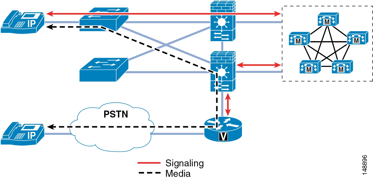
IP Telephony networks have unique data flows. The phones use a client/server model for signaling for call setup, and Cisco Unified CallManager controls the phones through that signaling. The data flows for the IP Telephony RTP streams are more like a peer-to-peer network, and the phones or gateways talk directly to each other via the RTP streams. If the signaling flows do not go through the firewall so that the firewall can inspect the signaling traffic, the RTP streams could be blocked because the firewall will not know which ports need to be opened to allow the RTP streams for a conversation.
A firewall placed in a correctly designed network can force all the data through that device, so capacities and performance need to be taken into account. Performance includes the amount of latency, which can be increased by a firewall if the firewall is under high load or even under attack. The general rule in an IP Telephony deployment is to keep the CPU usage of an FWSM, ASA, or PIX to less than 60% for normal usage. If the CPU runs over 60%, it increases the chance of impacting IP phones, call setup, and registration. If the CPU usage stays at a sustained level above 60%, the registered IP phones will be affected, quality of calls in progress will degrade, and call setup for new calls will suffer. In the worst case, if the sustained CPU usage stays above 60%, phones will start to unregister. When this happens, they will attempt to re-register with Cisco Unified CallManager, thus increasing the load on the firewalls even more. If this were to happen, the effect would be a rolling blackout of phones unregistering and attempting to re-register with Cisco Unified CallManager. Until the CPU usage of the firewall decreases to under 60% sustained load, this rolling blackout would continue and most (if not all) of the phones would be affected. If you are currently using a Cisco firewall in your network, you should monitor the CPU usage carefully when adding IP Telephony traffic to your network so that you do not adversely affect that traffic.
There are many ways to deploy firewalls. This section concentrates on the ASA, PIX, and FWSM in the active/standby mode in both routed and transparent scenarios. Each of the configurations in this section is in single-context mode within the voice sections of the firewall configurations.
All of the Cisco firewalls can run in either multiple-context or single-context mode. In single-context mode, the firewall is a single firewall that controls all traffic flowing through it. In multiple-context mode, the firewalls can be turned into many virtual firewalls. Each of these contexts or virtual firewalls have their own configurations and can be controlled by different groups or administrators. Each time a new context is added to a firewall, it will increase the load and memory requirements on that firewall. When you deploy a new context, make sure that the CPU requirements are met so that voice RTP streams are not adversely affected.
Functionality Differences of the ASA or PIX and the FWSM
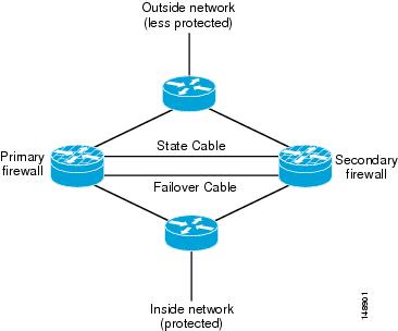
Figure 20-16 shows a logical representation of redundant firewalls in a network. Placement is the same for both routed configurations and transparent configurations.
Figure 20-16 Redundant Routed or Transparent Firewalls
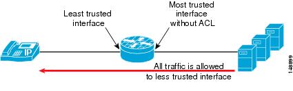
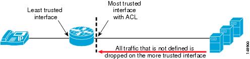
Both the Cisco Adaptive Security Appliance (ASA) and the Cisco Private Internet Exchange (PIX) operate in a different manner than the Cisco Firewall Services Modules (FWSM). Within an ASA or PIX, as long as there are no ACLs on a more trusted interface, all traffic from that interface is trusted and allowed out to a less-trusted interface. (See Figure 20-17.) For example, all traffic from the inside or data center interface of an ASA will be allowed to go out to the outside interface of the ASA. Once any ACL is applied to the more trusted interface on a ASA/PIX, all other traffic is denied (DENY) and the firewall will then function very much like the FWSM. (See Figure 20-18.)
Figure 20-17 Functionality of a Cisco ASA or PIX
Figure 20-18 Functionality of a Cisco FWSM
Overall Advantages of Firewalls
A firewall provides a security control point in the network for applications that run over the network. A firewall also provides dynamic opening of ports for IP Telephony conversations if that traffic is running through the firewall.
Using its Application Layer Gateway (ALG) capability, the firewall can inspect the traffic that runs though it to determine if that traffic is really the type of traffic that the firewall is expecting. For example, does the HTTP traffic really look like HTTP traffic, or is it an attack? If it is an attack, then drop that packet and do not allow that packet to get to the HTTP server behind the firewall.
Overall Disadvantages of Firewalls
Not all IP Telephony application servers or applications are supported through a firewall. Some applications that are not supported with firewalls or with an ALG in the firewall include Cisco Unity voicemail servers, Attendant Console, Cisco Unified Contact Center Enterprise, and Cisco Unified Contact Center Express. ACLs can be written for these applications to allow traffic to flow through a firewall.
SCCP video is not supported through any of the firewalls currently shipping (up to and including versions of ASA/PIX 7.1x and FWSM 3.1.x). SIP used on Cisco Unified CallManager 5.x is not currently supported though the firewalls using ALGs. If SIP signaling or media is required to traverse the firewalls, ACLs must be used until support is available.
Versions of Cisco FWSM prior to version 3.0 do not support SCCP fragmentation. If an SCCP packet is fragmented from a phone, from Cisco Unified CallManager, or from a gateway to another IP Telephony device, the fragmented packet will not be allowed through the FWSM. In cases where fragmentation occurs with an FWSM running version 2.x code, an ACL should be used without the ALG feature of the firewall for the signaling traffic. This configuration will allow the signaling traffic through the FWSM but will not do packet inspection as the signaling goes through the firewall.
To determine if the applications running on your network are supported with the version of firewall in the network or if ACLs have to be written, refer to the appropriate application documentation available at
Routed ASA and PIX
The ASA or PIX firewall in routed mode acts as a router between connected networks, and each interface requires an IP address on a different subnet. In single-context mode, the routed firewall supports Open Shortest Path First (OSPF) and Routing Information Protocol (RIP) in passive mode. Multiple-context mode supports static routes only. Cisco recommends using the advanced routing capabilities of the upstream and downstream routers instead of relying on the security appliance for extensive routing needs. For more information on the routed mode, refer to the Cisco Security Appliance Command Line Configuration Guide, available at
http://www.cisco.com/en/US/products/ps6120/products_configuration_guide_book09186a0080450278.html
Advantages
The routed ASA or PIX firewall supports QoS, NAT, and VPN termination to the box, which are not supported in the transparent mode (see Transparent ASA and PIX).
Figure 20-16 shows the logical placement of firewalls for both routed and transparent configurations in active standby mode. With the routed configuration, each interface on the ASA or PIX would have an IP address. In the transparent mode, there would be no IP address on the interfaces other then the IP address to manage the ASA or PIX remotely.
Disadvantages
Unlike with transparent mode, the device can be seen in the network and, because of that, it can be a point of attack. Placing a routed ASA or PIX firewall in a network changes the network routing because some of the routing can be done by the firewall. IP addresses must also be available for all the interfaces on the firewall that are going to be use, so changing the IP addresses of the routers in the network might also be required. If a routing protocol or RSVP is to be allowed through the ASA or PIX firewall, then an ACL will have to be put on the inside (or most trusted) interface to allow that traffic to pass to the outside (or lesser trusted) interfaces. That ACL must also define all other traffic that will be allowed out of the most trusted interface.
Transparent ASA and PIX
The ASA or PIX firewall can be configured to be a Layer 2 firewall (also known as "bump in the wire" or "stealth firewall"). In this configuration, the firewall does not have an IP address (other than for management proposes), and all of the transactions are done at Layer 2 of the network. Even though the firewall acts as a bridge, Layer 3 traffic cannot pass through the security appliance unless you explicitly permit it with an extended access list. The only traffic allowed without an access list is Address Resolution Protocol (ARP) traffic.
Advantages
This configuration has the advantage that an attacker cannot see the firewall because it is not doing any dynamic routing. Static routing is required to make the firewall work even in transparent mode.
This configuration also makes it easier to place the firewall into an existing network because routing does not have to change for the firewall. It also makes the firewall easier to manage and debug because it is not doing any routing within the firewall. Because the firewall is not processing routing requests, the performance of the firewall is usually somewhat higher with inspect commands and overall traffic than the same firewall model and software that is doing routing.
Disadvantages
With transparent mode, you are unable to use NAT on the firewall. If you are going to pass data for routing, you will also have to define the ACLs both inside and outside the firewall to allow traffic, unlike with the same firewall in routed mode. Cisco Discovery Protocol (CDP) traffic will not pass through the device even if it is defined. Each directly connected network must be on the same subnet. You cannot share interfaces between contexts; if you plan on running multiple-context mode, you will have to use additional interfaces. You must define all non-IP traffic, such as routing protocols, with an ACL to allow that traffic through the firewall. QoS is not supported in transparent mode. Multicast traffic can be allowed to go through the firewall with an extended ACL, but it is not a multicast device. In transparent mode, the firewall does not support VPN termination other than for the management interface.
If a routing protocol or RSVP is to be allowed through the ASA or PIX firewall, then an ACL will have to be put on the inside (or most trusted) interface to allow that traffic to pass to the outside (or lesser trusted) interfaces. That ACL must also define all other traffic that will be allowed out of the most trusted interface.
For more information on the transparent mode, refer to the Cisco Security Appliance Command Line Configuration Guide, available at
http://www.cisco.com/en/US/products/ps6120/products_configuration_guide_book09186a0080450278.html
ASA and PIX Configuration Example
The following configuration example lists the ports and inspect commands that are used to make the firewalls work with voice for ASA and PIX software Release 7.04. This is an example only, and you should review the ports list from all the applications that are used in your network before deploying any firewall. This configuration example shows only the voice sections.
!!object-group service remote-access tcpdescription remote access!Windows terminalport-object range 3389 3389!VNCport-object range 5800 5800!VNCport-object range 5900 5900port-object range 8080 8080port-object eq ssh!SSHport-object eq ftp-data!FTP data transportport-object eq www!HTTP Accessport-object eq ftp!FTPport-object eq https!HTTPS Accessobject-group service voice-protocols-tcp tcpdescription TCP voice protocolsCTI/QBEport-object range 2428 2428!SIP communicationport-object eq ctiqbe!SCCPport-object range 2000 2000!Secure SCCPport-object range 2443 2443object-group service voice-protocols-udp udp!TFTPport-object eq tftp!MGCP Signalingport-object range 2427 2427!DNSport-object eq domain!RASport-object range 1719 1719!SIP!Object Group applied for remote-accessaccess-list OUTSIDE extended permit tcp any any object-group remote-access!Object Group applied for voice-protocols-tcpaccess-list OUTSIDE extended permit tcp any any object-group voice-protocols-tcp!Object Group applied for voice-protocols-udpaccess-list OUTSIDE extended permit udp any any object-group voice-protocols-udp! Object Group applied for remote-accessaccess-list inside_access_in extended permit tcp any any object-group remote-access! Object Group applied for voice-protocols-tcpaccess-list inside_access_in extended permit tcp any any object-group voice-protocols-tcp! Object Group applied for voice-protocols-udpaccess-list inside_access_in extended permit udp any any object-group voice-protocols-udp!Failover configip address 172.19.245.3 255.255.255.248 standby 172.19.245.4failoverfailover lan unit primaryfailover lan interface failover GigabitEthernet0/3failover polltime unit 1 holdtime 3!Lowest and fastest setting for failoverfailover polltime interface 3failover link failover_state GigabitEthernet0/2failover interface ip failover 192.168.1.1 255.255.255.0 standby 192.168.1.2failover interface ip failover_state 192.168.0.1 255.255.255.0 standby 192.168.0.2!!Default inspection with inspects enabledclass-map inspection_defaultmatch default-inspection-traffic!!policy-map global_policyclass inspection_defaultinspect h323 h225inspect h323 rasinspect skinnyinspect sipinspect tftpinspect mgcpFWSM Routed Mode
In routed mode, the FWSM is considered to be a router hop in the network. It performs NAT between connected networks and can use OSPF or passive RIP (in single-context mode). Routed mode supports up to 256 interfaces per context or in single mode, with a maximum of 1000 interfaces divided between all contexts.
Advantages
As a routed device in your network, the FWSM supports routing and all other features that are not available in transparent mode.
Disadvantages
Unlike the transparent mode, the routed device is visible in the network and, because of that, it can be a point of attack. To place the device in a network, IP addressing and routing must be change.
FWSM Transparent Mode
In transparent mode, the FWSM acts like a "bump in the wire," or a "stealth firewall," and is not a router hop. The FWSM connects the same network on its inside and outside interfaces, but each interface must be on a different VLAN. No dynamic routing protocols or NAT are required. However, like routed mode, transparent mode also requires ACLs to allow traffic to pass through. Transparent mode can also optionally use EtherType ACLs to allow non-IP traffic. Transparent mode supports only two interfaces, an inside interface and an outside interface.
You might use a transparent firewall to simplify your network configuration. Transparent mode is also useful if you want the firewall to be invisible to attackers. You can also use a transparent firewall for traffic that would otherwise be blocked in routed mode. For example, a transparent firewall can allow multicast streams using an EtherType ACL.
Advantages
This configuration has the advantage that an attacker cannot see the firewall because it is not doing any routing. This configuration also makes it easier to place the firewall into an existing network because routing does not have to change for the firewall. It also makes the firewall easier to manage and debug because it is not doing any routing within the firewall. You can also bridge non-IP traffic and IP multicast traffic, static ARP inspection, and MAC move detection and static MAC.
Disadvantages
To avoid loops when you use failover in transparent mode, you must use switch software that supports Bridge Port Data Unit (BPDU) forwarding, and you must configure the FWSM to allow BPDUs. Transparent mode does not support NAT, dynamic routing, or a unicast reverse path forwarding (RPF) check. There is no NAT 0 with the FWSM in transparent mode.
FWSM Configuration Example
The following configuration example lists the ports and inspect commands that are used to make the firewalls work with voice for FWSM software Release 2.3.x. This is only an example, and you should review the ports list from all the applications that are used in your network before deploying any firewall. This configuration example shows only the voice sections.
fixup protocol h323 H225 1720!Enable fixup h3232 h225fixup protocol h323 ras 1718-1719!Enable fixup h323 RASfixup protocol mgcp 2427!Enable fixup mgcpfixup protocol skinny 2000!Enable fixupfixup protocol tftp 69!Enable fixupobject-group service VoiceProtocols tcpdescription Unified CM Voice protocolsport-object eq ctiqbeport-object eq 2000port-object eq 3224port-object eq 2443port-object eq 2428port-object eq h323!Defining the ports for TCP voiceobject-group service VoiceProtocolsUDP udpdescription UDP based Voice Protocolsport-object range 2427 2427port-object range 1719 1719port-object eq tftp!Defining the ports for UDP voiceobject-group service RemoteAccess tcpdescription Remote Accesport-object range 3389 3389port-object range 5800 5809port-object eq sshport-object range 5900 5900port-object eq wwwport-object eq https!Defining remote access TCP portsaccess-list inside_nat0_outbound extended permit ip any any!access-list phones_access_in extended permit tcp any any object-group RemoteAccess log notifications interval 2access-list phones_access_in extended permit tcp any any object-group VoiceProtocols log notifications interval 2access-list phones_access_in extended permit udp any any object-group VoiceProtocolsUDP log notifications interval 2access-list phones_access_in extended deny ip any any log notifications interval 2access-list outside_access_in extended permit tcp any any object-group VoiceProtocols log notifications interval 2access-list outside_access_in extended permit tcp any any object-group RemoteAccess log notifications interval 2access-list outside_access_in extended permit udp any any object-group VoiceProtocolsUDP log notifications interval 2!Access lists applying the object groups defined above for inside and outside interfacesaccess-list outside_access_in extended deny ip any any log notifications interval 2access-list inside_access_in extended deny ip any any!Deny all other trafficaccess-list phones_nat0_outbound extended permit ip any any!failoverfailover lan unit primaryfailover lan interface flan vlan 4050failover polltime unit 1 holdtime 5failover polltime interface 15!Failover config - 15 secondsfailover interface-policy 50%failover link flin vlan 4051failover interface ip flan 1.1.1.1 255.255.255.252 standby 1.1.1.2failover interface ip flin 1.1.1.5 255.255.255.252 standby 1.1.1.6nat (inside) 0 access-list inside_nat0_outbound_V1access-group outside_access_in in interface outsideaccess-group inside_access_in in interface insideData Center
Within the data center, the security policy should define what security is needed for the IP Telephony applications servers. Because the Cisco Unified Communications servers are based on IP, the security that you would put on any other time-sensitive data within a data center could be applied to those servers as well.
If clustering over the WAN is being used between data centers, any additional security that is applied both within and between those data centers has to fit within the maximum round-trip time that is allowed between nodes in a cluster. If your current security policy for application servers within your network covers the IP Telephony servers from Cisco, then you should use that security. You can also use any of the infrastructure security that is already deployed.
To design appropriate data center security for your data applications, Cisco recommends following the guidelines presented in the Data Center Networking: Server Farm Security SRND (Server Farm Security in the Business Ready Data Center Architecture), available at
Applications Servers
For a list of the Cisco Unified CallManager security features and how to enable them, refer to the Cisco Unified CallManager Security Guide, available at
http://www.cisco.com/en/US/products/sw/voicesw/ps556/prod_maintenance_guides_list.html
Before enabling any of the Cisco Unified CallManager security features, verify that they will satisfy the security requirements specified in your enterprise security policy for these types of devices in a network.
Cisco Security Agent on the Cisco Unified CallManager and Application Servers
The Cisco Security Agent is used on most of the application servers that Cisco uses to provide IP Telephony and IP Telephony services. The Cisco Security Agent software is Host Intrusion Prevention software that looks at the behavior of the traffic to and from the server, and the way the applications are running on that server, to determine if everything is working correctly. If something is considered abnormal, then the Cisco Security Agent software prevents that activity from happening. For example, if a virus is trying to install a software package on a Cisco Unified CallManager and that is something that has never happened before, the virus would be prevented from installing. Antivirus software is still needed on the server because Cisco Security Agent cannot clean a server that has been infected; it can only prevent the infection.
Unmanaged Cisco Security Agent
Cisco developed a default Cisco Security Agent policy for its servers that allows all the correct things needed for that IP Telephony server to function, while also preventing known and unknown attacks from affecting the IP Telephony servers. At a minimum, you should install and run this unmanaged version Cisco Security Agent. This software protects the application and the operating system from both viruses and worm attacks. To get the maximum protection from these types of intrusions, ensure that the newest version of the Cisco Security Agent software is always installed on your servers. With the unmanaged agent installed on your servers, you will be able to see the logs of attacks on only the system where the agent is installed. You will have to log into each system to check the log files that might be there because of some type of alarm that has occurred.
Advantages
The unmanaged Cisco Security Agent protects each system from both known and unknown attacks, worms, and viruses.
Disadvantages
When run in unmanaged mode, Cisco Security Agent does not correlate alarms, and you have to access each system individually to see the log files on that system. When you upgrade the unmanaged Cisco Security Agent, you have to install the new client and usually reboot the system to make the client settings take effect. Cisco Security Agent cannot clean a system if that system does become infected for some reason. You also have to run an antivirus software on the system to help maintain security and protect the system.
Managed Cisco Security Agent
Managed Cisco Security Agent works in the same way as the unmanaged version, but some additional benefits come along with the management console. If you run the managed system, you will receive all the alarms from all of the systems on one console. This feature also enables you to be notified of any anomaly by being emailed or paged if an anomaly reaches a critical level.
Note
Advantages
Managed Cisco Security Agent provides the same protection as the unmanaged system, but it also gives you control of the agent. This control allows for the correlation of events, global reporting back to the management console, and upgrades to the Cisco Security Agent configuration of the agent without reloading the system when you have an update.
Disadvantages
A separate piece of software is required on a separate server for global monitoring and configuration of the managed agent. Cisco Security Agent cannot clean a system if that system does become infected for some reason. You must also run an antivirus software on the system to help maintain security and protect the system.
Antivirus
Approved antivirus software should be run on all of the IP Telephony servers and IP Telephony application servers that have been approved to run that software. As with any other server in a network, antivirus software helps protect the Cisco Unified CallManager server from being infected with a worm or a virus that could impact call processing. The Cisco Security Agent should not be the only preventative software installed on the system because Cisco Security Agent cannot clean the system of infection. Only an antivirus software can clean and infected system.
Additional information about running antivirus software on the Cisco Unified CallManager servers is available at
http://www.cisco.com/en/US/products/sw/voicesw/ps556/tsd_products_support_series_home.html
Advantages
Antivirus software helps prevent the application server from being infected and suffering performance degradation.
Disadvantages
Managing the antivirus software involves some overhead. In addition, you must ensure that the version of software is approved for installation on Cisco Unified CallManager and the other IP Telephony application servers.
General Server Guidelines
Your Cisco Unified CallManager and other IP Telephony application servers should not be treated as normal servers. Anything you do while configuring the system could affect calls that are trying to be places or that are in progress. As with any other business-class application, major configuration changes should be done within maintenance windows to keep from disrupting phone conversations.
Standard security policies for application servers might not be adequate for IP Telephony servers. Unlike email servers or web servers, voice servers will not allow you to refresh a screen or re-send a message. The voice communications are real-time events. Any security policy for IP Telephony servers should ensure that work that is not related to configuring or managing the voice systems is not done on the IP Telephony servers at any time. Activities that might be considered normal on application servers within a network (for example, surfing the internet) should not take place on the IP Telephony servers.
In addition, Cisco provides a well defined patch system for the IP Telephony servers, and it should be applied based on the patch policy within your IT organization. You should not patch the system normally using the OS vendor's patch system unless it is approved by Cisco Systems. All patches should be downloaded from Cisco or from the OS vendor as directed by Cisco Systems, and applied according to the patch installation process.
Additional information on how to increase the hardening of the OS for Cisco Unified CallManager is listed in the C:\Utils\SecurityTemplates directory on your Cisco Unified CallManager server. You should use the OS hardening techniques if your security policy requires you to lock down the OS even more than what is provided in the default installation.
Various software patches are available at the following location:
http://www.cisco.com/public/sw-center/sw-voice.shtml
Note
The above site also contains a notification tool that will email you when a critical patch must be applied to an IP Telephony server.
Advantages
General server security practices help to mitigate viruses and worms if the application server is treated like a PBX and not like other application servers.
Disadvantages
When the additional security features are configured, some of the Cisco Unified CallManager functionality might be reduced. Also, additional care is needed during upgrades because some of the services that are disabled for the additional security will have to be enabled for a successful upgrade.
Deployment Examples
This section presents examples of what could be done from a security perspective for a lobby phone and a firewall deployment. A good security policy should be in place to cover deployments similar to these types.
Lobby Phone Example
The example in this section illustrates one possible way to configure a phone and a network for use in an area with low physical security, such as a lobby area. None of the features in this example are required for a lobby phone, but if your security policy states more security is needed, then you could use the features listed in this example.
Because you would not want anyone to gain access to the network from the PC port on the phone, you should disable the PC port on the back of the phone to limit network access (see PC Port on the Phone). You should also disable the settings page on the phone so that potential attackers cannot see the IP addresses of the network to which the lobby phone is connected (see Settings Access). The disadvantage of not being able to change the settings on the phone usually will not matter for a lobby phone.
Because there is very little chance that a lobby phone will be moved, you could use a static IP address for that phone. A static IP address would prevent an attacker from unplugging the phone and then plugging into that phone port to get a new IP address (see IP Addressing). Also, if the phone is unplugged, the port state will change and the phone will no longer be registered with Cisco Unified CallManager. You can track this event in just the lobby phone ports to see if someone is trying to attach to the network.
Using static port security for the phone and not allowing the MAC address to be learned would mean that an attacker would have to change his MAC address to that of the phone, if he were able to discover that address. Dynamic port security could be used with an unlimited timer to learn the MAC address (but never unlearn it), so that it would not have to be added. Then the switchport would not have to be changed to clear that MAC address unless the phone is changed. The MAC address is listed in a label on the bottom of the phone. If listing the MAC address is considered a security issue, the label can be removed and replaced with a "Lobby Phone" label to identify the device. (See Switch Port.)
A single VLAN could be used and Cisco Discovery Protocol (CDP) could be disabled on the port so that attackers would not be able to see any information from the Ethernet port about that port or switch to which it is attached. In this case, the phone would not have a CDP entry in the switch for E911 emergency calls, and each lobby phone would need either a label or an information message to local security when an emergency number is dialed.
A static entry in the DHCP Snooping binding table could be made because there would be no DHCP on the port (see DHCP Snooping: Prevent Rogue DHCP Server Attacks). Once the static entry is in the DHCP Snooping binding table, Dynamic ARP Inspection could be enabled on the VLAN to keep the attacker from getting other information about one of the Layer 2 neighbors on the network (see Requirement for Dynamic ARP Inspection).
With a static entry in the DHCP Snooping binding table, IP Source Guard could be used (see IP Source Guard). If an attacker got the MAC address and the IP address and then started sending packets, only packets with the correct IP address could be sent.
A VLAN ACL could be written to allow only the ports and IP addresses that are needed for the phones to operate (see VLAN Access Control Lists). The following example contains a very small ACL that can be applied to a port at Layer 2 or at the first Layer 3 device to help control access into the network (see Router Access Control Lists). This example is based on a Cisco 7960 IP Phone being used in a lobby area, without music on hold to the phone or HTTP access from the phone.
This example uses the following IP address ranges:
•
•
•
•
•
10 permit icmp any any! Allow all icmp - phone to phone, gateway to phone and NMS to phone20 permit udp host 10.0.10.2 eq 1985 any!Allow HSRP information in, do not allow out30 permit udp host 10.0.10.3 eq 1985 any! Allow in from HSRP neighbor40 permit udp host 10.0.40.5 range 49152 65535 10.0.20.0 0.0.0.255 eq tftp! Using ip host from ephemeral port range from phone to the TFPT server port 69 (start of tftp)50 permit udp 10.0.20.0 0.0.0.255 range 1024 5000 host 10.0.40.5 range 49152 65535!Using IP subnet from TFTP server with ephemeral port range to ip host and ephemeral port range for phone60 permit udp host 10.0.40.5 range 49152 65535 10.0.20.0 0.0.0.255 range 1024 5000! Using host from phone to TFTP server with ephemeral port range to ip range and ephemeral port range for TFTP (continue the TFTP conversation)70 permit udp host 10.0.40.5 range 49152 65535 host 10.0.30.2 eq domain! Using IP host and ephemeral port range from phone to DNS server host80 permit udp host 10.0.30.2 eq domain host 10.0.40.5 range 49152 65535! Using IP from DNS server to phone host ip and ephemeral port range90 permit tcp 10.0.40.5 range 49152 65535 10.0.20.0 0.0.0.255 eq 2000! Using IP host and ephemeral port range from phone to Unified CM cluster for SCCP100 permit tcp 10.0.20.0 0.0.0.255 eq 2000 host 10.0.40.5 range 49152 65535! Using IP range and SCCP port to phone IP host and ephemeral port range110 permit udp 10.0.0.0 0.0.255.255 range 16384 32767 host 10.0.40.5 range 16384 32767! Using IP range and ephemeral port range from all phones or gateways outside a vlan to the IP host to phone120 permit udp host 10.0.40.5 range 16384 32767 10.0.0.0 0.0.255.255 range 16384 43767! Using IP host and ephemeral port range from vlan to all other phones or gateways130 permit udp host 172.19.244.3 range 1024 5000 host 10.0.40.5 eq snmp!From IP host of NMS server and ephemeral port range (Different for Windows vs Sun) to IP host of phones and SNMP port (161)140 permit udp host 10.0.40.5 eq snmp host 172.19.244.3 range 1024 5000! From IP host of phone with SNMP port (161) to IP host of NMS server and ephemeral port rangeBasic QoS Example for a Lobby Phone
Set the voice stream to G.729 and use QoS to limit the amount of traffic that can be sent into the port (see Quality of Service). Even if the QoS maximum is exceeded, the traffic will be reset to CS1, or Scavenger Class, which is the lowest priority traffic in most enterprise networks.
CAT2970(config)#mls qos map policed-dscp 0 24 46 to 8! Excess traffic marked 0 or CS3 or EF will be remarked to CS1CAT2970(config)#CAT2970(config)#class-map match-all LOBBY-VOICECAT2970(config-cmap)# match access-group name LOBBY-VOICECAT2970(config-cmap)#class-map match-all LOBBY-SIGNALINGCAT2970(config-cmap)# match access-group name LOBBY-SIGNALINGCAT2970(config-cmap)#exitCAT2970(config)#CAT2970(config)#policy-map LOBBY-PHONECAT2970(config-pmap)#class LOBBY-VOICECAT2970(config-pmap-c)# set ip dscp 46 ! Lobby phone VoIP is marked to DSCP EFCAT2970(config-pmap-c)# police 48000 8000 exceed-action policed-dscp-transmit! Out-of-profile Lobby voice traffic (g.729) is marked down to Scavenger (CS1)CAT2970(config-pmap-c)#class LOBBY-SIGNALINGCAT2970(config-pmap-c)# set ip dscp 24 ! Signaling is marked to DSCP CS3CAT2970(config-pmap-c)# police 32000 8000 exceed-action policed-dscp-transmit! Out-of-profile Signaling traffic is marked down to Scavenger (CS1)CAT2970(config-pmap-c)#class class-defaultCAT2970(config-pmap-c)# set ip dscp 0CAT2970(config-pmap-c)# police 56000 8000 exceed-action policed-dscp-transmit! Out-of-profile data traffic is marked down to Scavenger (CS1)CAT2970(config-pmap-c)# exitCAT2970(config-pmap)#exitCAT2970(config)#CAT2970(config)#interface GigabitEthernet0/1CAT2970(config-if)# service-policy input LOBBY-PHONE ! Applies policy to intCAT2970(config-if)#exitCAT2970(config)#CAT2970(config)#ip access list extended LOBBY-VOICECAT2970(config-ext-nacl)# permit udp any any range 16384 32767 ! VoIP portsCAT2970(config-ext-nacl)#CAT2970(config-ext-nacl)#ip access list extended LOBBY-SIGNALINGCAT2970(config-ext-nacl)# permit tcp any any range 2000 2002 ! SCCP portsCAT2970(config-ext-nacl)#endCAT2970#Firewall Deployment Example (Centralized Deployment)
The example in this section is one way that firewalls could be deployed within the data center, with Cisco Unified CallManagers behind them (see Figure 20-19). In this example, the Cisco Unified CallManagers are in a centralized deployment, single cluster with all the phones outside the firewalls. Because the network in this deployment already contained firewalls that are configured in routed mode within the corporate data center, the load was reviewed before the placement of gateways was determined. After reviewing the average load of the firewall, it was decided that all the RTP streams would not transverse the firewall in order to keep the firewalls under the 60% CPU load (see Putting Firewalls Around Gateways). The gateways are placed outside the firewalls, and ACLs within the network are used to control the TCP data flow to and from the gateways from the Cisco Unified CallManagers. An ACL is also written in the network to control the RTP streams from the phones because the IP addresses of the phones are well defined (see IP Addressing). The voice applications servers are placed within the demilitarized zone (DMZ), and ACLs are used at the firewalls to control access to and from the Cisco Unified CallManagers and to the users in the network. This configuration will limit the amount of RTP streams through the firewall using inspects, which will minimize the impact to the firewalls when the new voice applications are added to the existing network.
Figure 20-19 Firewall Deployment Example
Conclusion
This chapter did not cover all of the security that could be enabled to protect the voice data within your network. The techniques presented here are just a subset of all the tools that are available to network administrators to protect all the data within a network. On the other hand, even these tools do not have to be enabled within a network, depending on what level of security is required for the data within the network overall. Choose your security methods wisely. As the security within a network increases, so do the complexity and troubleshooting problems. It is up to each enterprise to define both the risks and the requirements of its organization and then to apply the appropriate security within the network and on the devices attached to that network.