-
Cisco Unified Communications SRND Based on Cisco Unified CallManager 4.x
-
Preface
-
Introduction
-
IP Telephony Deployment Models
-
Network Infrastructure
-
Gateways
-
Cisco Unified CallManager Trunks
-
Media Resources
-
Music on Hold
-
Call Processing
-
Call Admission Control
-
Dial Plan
-
Emergency Services
-
Third-Party Voicemail Design
-
Cisco Unity
-
Cisco Unity Express
-
Cisco Unified MeetingPlace Integration
-
Cisco Unified MeetingPlace Express
-
IP Video Telephony
-
LDAP Directory Integration
-
IP Telephony Migration Options
-
Voice Security
-
IP Telephony Endpoints
-
Device Mobility
-
Recommended Hardware and Software Combinations
-
Glossary
-
Index
-
Table Of Contents
Planning for 911 Functionality
Public Safety Answering Point (PSAP)
Interface Points into the Appropriate 911 Networks
Dynamic ANI (Trunk Connection)
Emergency Response Location Mapping
Emergency Location Identification Number Mapping
Cisco Emergency Responder Considerations
Emergency Responder Version Compatibility with Cisco Unified CallManager
Device Mobility Across Call Admission Control Locations
Default Emergency Response Location
PSAP Callback to Shared Directory Numbers
Emergency Call Routing within a Cisco ER Cluster
Scalability Considerations for Cisco ER Clustering
Emergency Services
Emergency services are of great importance in the proper deployment of a voice system. This chapter presents a summary of the following major design considerations essential to planning for emergency calls:
•
Planning for 911 Functionality
•
This chapter presents some information specific to the 911 emergency networks as deployed in Canada and the United States. Many of the concepts discussed here are adaptable to other locales. Please consult with your local telephony network provider for appropriate implementation of emergency call functionality.
In the United States, some states have already enacted legislation covering the 911 functionality required for users in a multi-line telephone system (MLTS). The National Emergency Number Association (NENA) has also produced the Technical Information Document on Model Legislation Enhanced 911 for Multi-Line Telephone Systems, available online at
http://www.nena9-1-1.org/9-1-1TechStandards/TechInfoDocs/MLTS_ModLeg_Nov2000.PDF
The Federal Communications Commission (FCC) has also drafted a proposed new section to title 47, part 68, section 319, which is available at
http://www.apcointl.org/about/pbx/worddocs/mltspart68.doc
This chapter assumes that you are familiar with the generic 911 functionality available to residential PSTN users in North America. For more information on the subject, refer to the following URL for a description of the current state of E911 services in North America:
http://www.nena.org/florida/Directory/911Tutorial%20Study%20Guide.pdf
Planning for 911 Functionality
This section highlights some of the functionality requirements for lifeline calls in multi-line telephone systems (MLTS). In the context of this section, lifeline calls are 911 calls serviced by the North American public switched telephone network (PSTN).
When planning an MLTS deployment, first establish all of the physical locations where phone services are needed. The locations can be classified as follows:
•
•
•
The locations, or type of deployment, affect the criteria used to design and implement 911 services. The following sections describe the key criteria, along with typical and exceptional situations for each. When analyzing and applying these criteria, consider how they are affected by the phone locations in your network.
Public Safety Answering Point (PSAP)
The public safety answering point (PSAP) is the party responsible for answering the 911 call and arranging the appropriate emergency response, such as sending police, fire, or ambulance teams. The physical location of the phone making the 911 call is the primary factor in determining the appropriate PSAP for answering that call. Generally, each building is serviced by one local PSAP.
To determine the responsible PSAP for a given location, contact a local public safety information service such as the local fire marshal or police department. Also, the phone directory of the local exchange carrier usually lists the agency responsible for servicing 911 calls in a given area.
Typical Situation
•
•
Exceptional Situation
•
•
911 Network Service Provider
After identifying the responsible PSAPs, you must also identify the 911 network service providers to which each PSAP is connected. It is commonly assumed that PSAPs receive 911 phone calls from the PSTN, but that is not the case. Instead, 911 calls are carried over dedicated, regionally significant networks, and each PSAP is connected to one or more such regional networks. In the majority of cases, the incumbent Local Exchange Carrier (LEC) is the 911 network service provider for a PSAP. Some exceptions include military installations, university campuses, federal or state parks, or other locations where the public safety responsibility falls outside the jurisdiction of the local authorities and/or where a private network is operated by an entity other than a public local exchange carrier.
If you are in doubt about the 911 network service provider for a given PSAP, contact the PSAP directly to verify the information.
Typical Situation
•
•
Exceptional Situation
•
•
•
Interface Points into the Appropriate 911 Networks
For larger telephony systems, 911 connectivity might require many interface points. Typically, more than one E911 selective router is used within a LEC's territory, and these routers usually are not interconnected.
For example, an enterprise with a large campus could have the following situation:
•
•
•
•
•
This type of situation would require two separate interface points, one per E911 selective router. The information pertaining to the E911 selective router territories is generally kept by the incumbent LEC, and the local account representative for that LEC should be able to provide an enterprise customer with the pertinent information. Many LECs also provide the services of 911 subject matter experts who can consult with their own account representatives on the proper mapping of 911 access services.
Typical Situation
•
•
Exceptional Situation
•
•
Note
Interface Type
In addition to providing voice communications, the interfaces used to present 911 calls to the network must also provide identification data about the calling party.
Automatic Number Identification (ANI) refers to the E.164 number of the calling party, which is used by networks to route a 911 call to the proper destination. This number is also used by the PSAP to look up the Automatic Location Identification (ALI) associated with a call.
911 calls are source-routed, which means that they are routed according to the calling number. Even though different locations are all dialing the same number (911), they will reach different PSAPs based on their location of origin, which is represented by the ANI (calling number).
You can implement 911 call functionality with either of the following interface types:
•
•
While dynamic ANI assignment scales better (because it supports multiple ANIs) and lends itself to all but the smallest of applications, static ANI assignment can be used in a wider variety of environments, from the smallest to the largest systems.
Dynamic ANI (Trunk Connection)
The dynamic aspect of ANI refers to the fact that a system has many phones sharing access to the 911 network across the same interface, and the ANI transmitted to the network might need to be different for each call.
There are two main types of dynamic ANI interfaces:
•
•
PRI
This type of interface usually connects a telephony system to a PSTN Class 5 switch. The calling party number (CPN) is used at call setup time to identify the E.164 number of the calling party.
Most LECs treat the CPN differently when a call is made to 911. Depending upon the functionality available in the Class 5 switch and/or upon LEC or government policy, the CPN may not be used as the ANI for 911 call routing. Instead, the network may be programmed to use the listed directory number (LDN) or the bill-to number (BTN) for ANI purposes.
If the CPN is not used for ANI, then 911 calls coming from a PRI interface all look the same to the 911 network because they all have the same ANI, and they are all routed to the same destination (which might not be the appropriate one).
Some LECs offer a feature to provide CPN transparency through a PRI interface for 911 calls. With this feature, the CPN presented to the Class 5 switch at call setup is used as ANI to route the call. The feature name for this functionality varies, depending on the LEC. (For example, SBC calls it Inform 911 in California.)
Note
Note
Many Class 5 switches are connected to E911 selective routers through trunks that do not support more than one area code. In such cases, if PRI is used to carry 911 calls, then the only 911 calls that will be routed properly are those whose CPN (or ANI) have the same Numbering Plan Area (NPA) as the Class 5 switch.
Example
An MLTS is connected to a Class 5 switch in area code 514 (NPA = 514). If the MLTS were to send a 911 call on the PRI trunk, with a CPN of 450.555.1212, the Class 5 switch would send the call to the E911 selective router with an ANI of 514.555.1212 (instead of the correct 450.555.1212), yielding inappropriate routing and ALI lookup.
To use PRI properly as a 911 interface, the system planner must ensure that the CPN will be used for ANI and must properly identify the range of numbers (in the format NPA NXX TNTN) acceptable on the link. For example, if a PRI link is defined to accept ANI numbers within the range 514 XXX XXXX, then only calls that have a Calling Party Number with NPA = 514 will be routed appropriately.
CAMA
Centralized Automatic Message Accounting (CAMA) trunks also allow the MLTS to send calls to the 911 network, with the following differences from the PRI approach:
•
•
•
Note
Static ANI (Line Connection)
Static ANI provides a line (rather than a trunk) connection to the PSTN, and the ANI of the line is associated with all 911 calls made on that line, regardless to the CPN of the calling phone. A plain old telephone service (POTS) line is used for this purpose.
POTS lines are one of the simplest and most widely supported PSTN interfaces. A POTS line usually comes fully configured to accept 911 calls. In addition, the existing E911 infrastructure supports 911 calls from POTS lines very well.
The POTS approach has the following attributes:
•
•
•
•
•
All outgoing 911 calls through this type of interface are treated the same by the E911 network, and the tools that enable Cisco Unified CallManager to control the ANI presented to the E911 network (such as calling party transformation masks) are irrelevant because the ANI can be only the POTS line's number.
Emergency Response Location Mapping
The National Emergency Number Association (NENA) has recently proposed model legislation to be used by state and federal agencies in enacting the rules that govern 911 in enterprise telephony systems. One of the concepts in the NENA proposal is that of the emergency response location (ERL), which is defined as:
A location to which a 911 emergency response team may be dispatched. The location should be specific enough to provide a reasonable opportunity for the emergency response team to quickly locate a caller anywhere within it.
Rather than having to identify each phone's location individually, the requirement allows for the grouping of phones into a "zone," the ERL. The maximum size of the ERL may vary, depending upon local implementation of the legislation, but we will use 7000 square feet (sq ft) as a basis for discussion in this section. (The concepts discussed here are independent of the maximum ERL size that may be allowed in any given state or region.)
An emergency location identification number (ELIN) is associated with each ERL. The ELIN is a fully qualified E.164 number, used to route the call within the E911 network. The ELIN is sent to the E911 network for any 911 call originating from the associated ERL. This process allows more than one phone to be associated with the same fully qualified E.164 number for 911 purposes, and it can be applied to DID and non-DID phones alike.
Note
For example, assume a building has a surface area of 70,000 sq ft and 100 phones. In planning for 911 functionality, the building can be divided into 10 zones (ERLs) of 7000 sq ft each, and each phone can be associated with the ERL where it is located. When a 911 call is made, the ERL (which could be the same for multiple phones) is identified by sending the associated ELIN to the PSAP. If the phones were evenly distributed in this example, each group of 10 phones would have the same ERL and, therefore, the same ELIN.
The various legislations define a minimum number of phones (for example, 49) and a minimum surface area (for example, 40,000 sq ft) below which the requirements for MLTS 911 are not applicable. But even if the legislation does not require 911 functionality for a given enterprise, it is always best practice to provision for it.
Emergency Location Identification Number Mapping
In general, you must associate a single fully qualified E.164 number, known as the emergency location identification number (ELIN), with each ERL. (However, if using Cisco Emergency Responder, you can configure more than one ELIN per ERL.) The ELIN is used to route the call across the E911 infrastructure and is used by the PSAP as the index into the ALI database.
ELINs must meet the following requirements:
•
•
The ELIN mapping process can be one of the following, depending on the type of interface to the E911 infrastructure for a given ERL:
•
With this type of interface, the calling party number identification passed to the network is controlled by the MLTS. The telephony routing table of the MLTS is responsible for associating the correct ELIN with the call, based on the calling phone's ERL. Within Cisco Unified CallManager, the calling party number can be modified by using transformation masks for calls made to 911. For example, all phones located in a given ERL can share the same calling search space that lists a partition containing a translation pattern (911) and a calling party transformation mask that would replace the phone's CPN with the ELIN for that location.
•
With this type of interface, the calling party number identification passed to the network is controlled by the PSTN. This is the case if the interface is a POTS line. The ELIN is the phone number of the POTS line, and no further manipulation of the phone's calling party identification number is possible.
PSAP Callback
The PSAP might have to reach the caller after completion of the initial conversation. The PSAP's ability to call back relies on the information that it receives with the original incoming call.
The delivery of this information to the PSAP is a two-part process:
1.
2.
–
–
–
–
Typical Situation
•
•
•
•
Exceptional Situation
•
•
Nomadic Phone Considerations
All discussions in this chapter thus far have relied upon the assumption that the phone locations are static. If, however, phones are moved across ERL boundaries, then 911 calls from the newly relocated phone will not be routed correctly. Because it is now physically located in a different ERL, the phone should use the ELIN of its current ERL. If the configuration is not changed in the Cisco Unified CallManager database, the following events will occur:
•
•
•
•
•
The only way to remedy this situation is to manually update the phone's configuration (including its calling search space and location information) in Cisco Unified CallManager to reflect its new physical location.
Cisco Emergency Responder
Ease of administration for moves, adds, and changes is one of the key advantages of IP telephony technology. To provide for moves, adds, and changes that automatically update 911 information without user intervention, Cisco has developed a product called the Cisco Emergency Responder (Cisco ER).
Cisco ER provides the following primary functionality:
•
•
•
For more information on Cisco ER, refer to the section on Cisco Emergency Responder Considerations, and to the Cisco ER product documentation available online at
http://www.cisco.com/en/US/products/sw/voicesw/ps842/tsd_products_support_series_home.html
The key functionality of Cisco ER relies on the detection of the phone's location by discovery of the network port (Layer 2 port, such as a Fast Ethernet switched port) from which the phone made the 911 call. The discovery mechanism relies on two main assumptions:
•
•
Once Cisco ER discovers the originating port for the call, it associates the call with the pre-established ERL for the location of that port. This process also yields an association with a pre-established ELIN for the location and the selection of the appropriate egress point to the E911 infrastructure, based on the originating ERL.
With Cisco ER, the ERL-to-ELIN mapping process described in the preceding sections still applies, but with one variation: without Cisco ER, each ERL is associated with only one ELIN, but Cisco ER allows for the use of two or more ELINs per ERL. The purpose of this enhancement is to cover the specific case of more than one 911 call originating from a given ERL within the same general time period, as illustrated by the following examples.
Example 1
•
•
•
To work around this situation, Cisco ER allows you to define a pool of ELINs for each ERL. This pool provides for the use, in a round-robin fashion, of a distinct ELIN for each successive call. With the definition of two ELINs for ERL X in our example, we now have the situation described in Example 2.
Example 2
•
•
•
Of course, if a third 911 call were made but there were only two ELINs for the ERL, the situation would allow for callback functionality to properly reach only the last two callers in the sequence.
Emergency Call String
It is highly desirable to configure a dial plan so that the system easily recognizes emergency calls, whether an access code (for example, 9) is used or not. The emergency string for North America is generally 911. Cisco strongly recommends that you configure the system to recognize both the strings 911 and 9911.
Cisco also strongly recommends that you explicitly mark the emergency route patterns with Urgent Priority so that Cisco Unified CallManager does not wait for the inter-digit timeout (Timer T.302) before routing the call.
Other emergency call strings may be supported concurrently on your system. Cisco highly recommends that you provide your telephony system users with training on the selected emergency call strings.
Also, it is highly desirable that users be trained to react appropriately if they dial the emergency string by mistake. In North America, 911 may be dialed in error by users trying to access a long distance number through the use of 9 as an access code. In such a case, the user should remain on the line to confirm that there is no emergency, and therefore no need to dispatch emergency personnel. Cisco ER's on-site notification capabilities can help in identifying the phone at the origin of such spurious 911 calls by providing detailed accounts of all calls made to 911, including calls made by mistake.
Gateway Considerations
Consider the following factors when selecting the gateways to handle emergency calls for your system:
Gateway Placement
Within the local exchange carrier (LEC) networks, 911 calls are routed over a locally significant infrastructure based on the origin of the call. The serving Class 5 switches are connected either directly to the relevant PSAP for their location or to an E911 selective router, which itself is connected to a group of PSAPs significant for its region.
With Cisco's IP-based enterprise telephony architecture, it is possible to route calls on-net to gateways that are remotely situated. As an example, a phone located in San Francisco could have its calls carried over an IP network to a gateway situated in San Jose, and then sent to the LEC's network.
For 911 calls, it is critical to chose the egress point to the LEC network so that emergency calls are routed to the appropriate local PSAP. In the example above, a 911 call from the San Francisco phone, if routed to a San Jose gateway, could not reach the San Francisco PSAP because the San Jose LEC switch receiving the call does not have a link to the E911 selective router serving the San Francisco PSAP. Furthermore, the San Jose area 911 infrastructure would not be able to route the call based on a San Francisco calling party number.
As a rule of thumb, route 911 calls to a gateway physically co-located with the originating phone. Contact the LEC to explore the possibility of using a common gateway to aggregate the 911 calls from multiple locations. Be aware that, even if the 911 network in a given region lends itself to using a centralized gateway for 911 calls, it might be preferable to rely on gateways co-located with the calling phones to prevent 911 call routing from being impacted during WAN failures.
Gateway Blocking
It is highly desirable to protect 911 calls from "all trunks busy" situations. If a 911 call needs to be connected, it should be allowed to proceed even if other types of calls are blocked due to lack of trunking resources. To provide for such situations, you can dedicate an explicit trunk group just for 911 calls.
It is acceptable to route emergency calls exclusively to an emergency trunk group. Another approach is to send emergency calls to the same trunk group as the regular PSTN calls (if the interface permits it), with an alternative path to a dedicated emergency trunk group. This latter approach allows for the most flexibility.
As an example, we can point emergency calls to a PRI trunk group, with an alternate path (reserved exclusively for emergency calls) to POTS lines for overflow conditions. If we put 2 POTS lines in the alternate trunk group, we are guarantying that a minimum of two simultaneous 911 calls can be routed in addition to any calls that were allowed in the main trunk group.
If the preferred gateway becomes unavailable, it may be acceptable to overflow emergency calls to an alternate number so that an alternate gateway is used. For example, in North America calls dialed as 911 could overflow to an E.164 (non-911) local emergency number. This approach does not take advantage of the North American 911 network infrastructure (that is, there is no selective routing, ANI, or ALI services), and it should be used only if it is acceptable to the applicable public safety authorities and only as a last resort to avoid blocking the emergency call due to a lack of network resources.
Answer Supervision
Under normal conditions, calls made to an emergency number should return answer supervision upon connection to the PSAP. The answer supervision may, as with any other call, trigger the full-duplex audio connection between the on-net caller and the egress interface to the LEC's network.
With some North American LECs, answer supervision might not be returned when a "free" call is placed. This may be the case for some toll-free numbers (for example, 800 numbers). In exceptional situations, because emergency calls are considered "free" calls, answer supervision might not be returned upon connection to the PSAP. You can detect this situation simply by making a 911 test call. Upon connection to the PSAP, if audio is present, the call timer should record the duration of the ongoing call; if the call timer is absent, it is very likely that answer supervision was not returned. If answer supervision is not returned, Cisco highly recommends that you contact the LEC and report this situation because it is most likely not the desired functionality.
If this situation cannot be rectified by the Local Exchange Carrier, it would be advisable to configure the egress gateway not to require answer supervision when calls are placed to the LEC's network, and to cut through the audio in both directions so that progress indicator tones, intercept messages, and communications with the PSAP are possible even if answer supervision is not returned.
By default, Cisco IOS-based H.323 gateways must receive answer supervision in order to connect audio in both directions. To forego the need for answer supervision on these gateways, use the following commands:
•
This command provides the equivalent of receiving a progress indicator value of 8 (in-band information now available) when alerting is received. This command allows the POTS side of the gateway to connect audio toward the origin of the call.
•
This command allows audio cut-through in both the backward and forward directions before a Connect message is received from the destination switch. This command affects all Voice over IP (VoIP) calls when it is enabled.
Be advised that, in situations where answer supervision is not provided, the call detail records (CDRs) will not accurately reflect the connect time or duration of 911 calls. This inaccuracy can impede the ability of a call reporting system to document the relevant statistics properly for 911 calls.
In all cases, Cisco highly recommends that you test 911 call functionality from all call paths and verify that answer supervision is returned upon connection to the PSAP.
Cisco Emergency Responder Considerations
Device mobility brings about special design considerations for emergency calls. Cisco Emergency Responder (Cisco ER) can be used to track device mobility and to adapt the system's routing of emergency calls based on a device's dynamic physical location.
Emergency Responder Version Compatibility with Cisco Unified CallManager
Emergency Responder 1.3(1) is required for compatibility with Cisco Unified CallManager 5.0. For a full description of the compatibility between Emergency Responder and Cisco Unified CallManager software versions, refer to the Cisco Emergency Responder Administration Guide 1.3(1), available at
Device Mobility Across Call Admission Control Locations
In a centralized call processing deployment, Cisco ER cannot fully support device movement across call admission control locations because Cisco Unified CallManager does not know about device movements. For example, if you physically move a phone from Branch A to Branch B but the phone's call admission control location remains the same (for example, Location_A), then it is possible that calls made to 911 from that phone would be blocked due to call admission control denial if all available bandwidth to Location_A is in use for other calls. This call blocking occurs even if the phone, now in location B, is physically co-located with the gateway used to connect to the PSAP for location B.
For the same reasons, Cisco ER cannot support device movement across gatekeeper-controlled call admission control zones. However, Cisco ER can fully support device movements within a call admission control location.
In centralized call processing deployments, Cisco ER automatically supports device movement within branches. However, if a device is moved between branches, manual intervention is required to adapt the device's location and region parameters before Cisco ER can fully support 911 calls.
Default Emergency Response Location
If Cisco ER cannot directly determine the physical location of a phone, it assigns a default emergency response location (ERL) to the call. The default ERL points all such calls to a specific PSAP. Although there is no universal recommendation as to where calls should be sent when this situation occurs, it is usually desirable to choose a PSAP that is centrally located and that offers the largest public safety jurisdiction. It is also advisable to populate the ALI records of the default ERL's emergency location identification numbers (ELINs) with contact information for the enterprise's emergency numbers and to offer information about the uncertainty of the caller's location. In addition, it is advisable to mark those ALI records with a note that a default routing of the emergency call has occurred.
Soft Clients
In cases where soft clients such as Cisco IP Communicator are used within the enterprise, Cisco ER can provide device mobility support. However, if the soft client is used outside the boundaries of the enterprise (for example, VPN access from a home office or hotel), Cisco ER will not be able to determine the location of the caller. Furthermore, it is unlikely that the Cisco system would have a gateway properly situated to allow sending the call to the appropriate PSAP for the caller's location.
It is a matter of enterprise policy to allow or not to allow the use of soft clients for 911 calls. It is highly advisable to disallow 911 calls by policy for soft clients that can roam across the internet. Nevertheless, if such a user were to call 911, the best-effort system response would be to route the call to either an on-site security force or a large PSAP close to the system's main site.
The following paragraph is an example notice that you could issue to users to warn them that emergency call functionality is not guaranteed to soft client users:
Emergency calls should be placed from phones that are located at the site for which they are configured (for example, your office). A local safety authority might not answer an emergency call placed from a phone that has been removed from its configured site. If you must use this phone for emergency calls while away from your configured site, be prepared to provide the answering public safety authority with specific information regarding your location. Use a phone that is locally configured to the site (for example, your hotel phone or your home phone) for emergency calls when traveling or telecommuting.
Test Calls
For any enterprise telephony system, it is a good idea to test 911 call functionality, not only after the initial installation, but regularly, as a preventive measure.
The following suggestions can help you carry out the testing:
•
•
•
•
•
PSAP Callback to Shared Directory Numbers
Cisco ER handles the routing of inbound calls made to emergency location identification numbers (ELINs). In cases where the line from which a 911 call was made is a shared directory number, the PSAP callback will cause all shared directory number appearances to ring. Any of the shared appearances can then answer the call, which means that it may not be the phone from which the 911 call originated.
Multi-Cluster Considerations
Enterprise telephony systems based on multiple Cisco Unified CallManager clusters can benefit from the functionality of Cisco Emergency Responder (Cisco ER).
The Cisco Emergency Responder Administration Guide provides detailed descriptions of the terms used herein, as well as the background information required to support the following discussion. Of specific interest is the chapter on Planning for Cisco Emergency Responder. This documentation is available at
Single Cisco ER Group
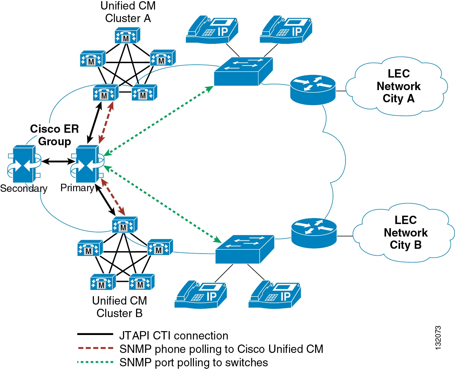
A single Emergency Responder group can be deployed to handle emergency calls from two or more Cisco Unified CallManager clusters. The design goal is to ensure that any phone's emergency call is routed to the Cisco ER group, which will assign an ELIN and route the call to the appropriate gateway based on the phone's location.
One advantage of using a single Cisco ER group is that all ERLs and ELINs are configured into a single system. A phone registered on any cluster will be located by the single Cisco ER group because that group is responsible for polling all of the system's access switches. Figure 11-1 illustrates a single Cisco ER group interfaced with two Cisco Unified CallManager clusters.
Figure 11-1 A Single Cisco ER Group Connected to Two Cisco Unified CallManager Clusters
The single Cisco ER group in Figure 11-1 interfaces with the following components:
•
•
•
The version of the JTAPI interface used by Cisco Emergency Responder is determined by the version of the Cisco Unified CallManager software to which it is connected. At system initialization, Cisco ER interrogates the Cisco Unified CallManager cluster and loads the appropriate JTAPI Telephony Service Provider (TSP). Because there can be only one version of JTAPI TSP on the Cisco ER server, all Cisco Unified CallManager clusters to which a single Cisco ER group is interfaced must run the same version of Cisco Unified CallManager software.
For some deployments, this software version requirement might present some difficulties. For instance, during a Cisco Unified CallManager upgrade, different clusters will be running different versions of software, and some of the clusters will be running a version of JTAPI that is not compatible with the version running on the Cisco ER servers. When this situation occurs, emergency calls from the cluster running a version of JTAPI different than that of the Cisco ER group might receive the call treatment provided by the Call Forward Busy settings of the emergency number's CTI Route Point.
When considering if a single Cisco ER group is appropriate for multiple Cisco Unified CallManager clusters, apply the following guidelines:
•
•
For example, a deployment with one large eight-server cluster in parallel with a small two-server cluster could be considered for use with a single Cisco ER group. In this case, it would be best to upgrade the large cluster first, thus minimizing the number of users (those served by the small cluster) that might be without Cisco ER service during the maintenance window of the upgrade. Furthermore, the small cluster's users can more appropriately be served by the temporary static routing of emergency calls in effect while Cisco ER is not reachable because they can be identified by the single ERL/ELIN assigned to all non-ER calls made during that time.
Note
Multiple Cisco ER Groups
Multiple Cisco ER groups can also be deployed to support multi-cluster systems. In this case, each ER group interfaces with the following components:
•
–
–
•
This approach allows Cisco Unified CallManager clusters to run different versions of software because each is interfaced to a separate Cisco ER group.
To allow phones to roam between various parts of the network and still be tracked by Cisco ER, you might have to configure the Cisco ER groups into a Cisco ER cluster. For details on Cisco ER clusters and groups, refer to the chapter on Planning for Cisco Emergency Responder in the Cisco Emergency Responder Administration Guide, available at
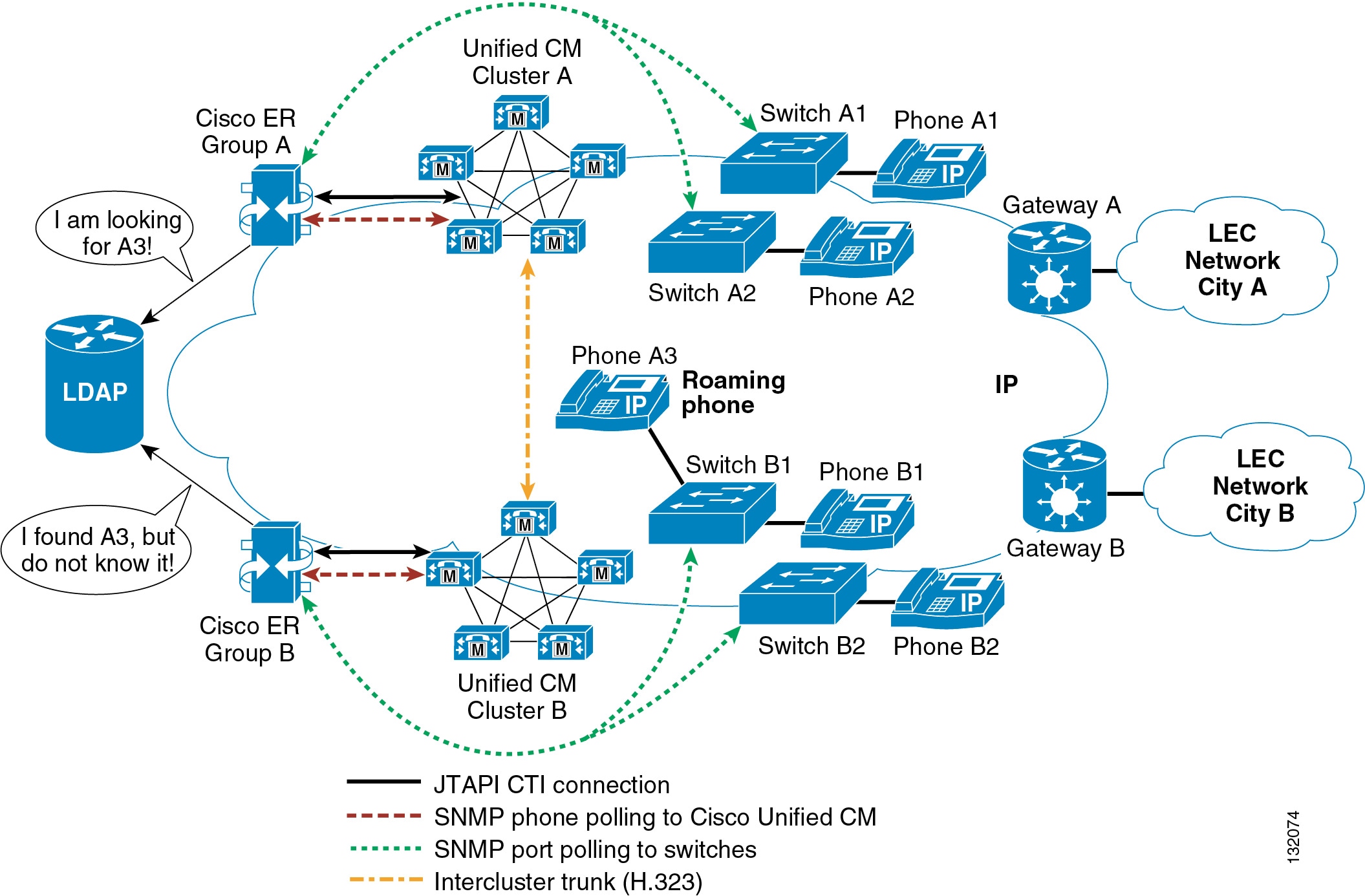
Figure 11-2 presents a sample topology illustrating some of the basic concepts behind Cisco ER clustering.
Figure 11-2 Multiple Cisco ER Groups
Figure 11-2 illustrates the following topology:
•
•
Note
Phone Movements Within the Tracking Domain of a Cisco ER Group
The emergency call processing for phones moving between access switches controlled by the same home Cisco ER group is the same as the processing done for a deployment with a single Cisco Unified CallManager cluster. For example, a phone moving between access switches A1 and A2 remains registered with Cisco Unified CallManager cluster A, and its location is determined by Cisco ER group A both before and after the move. The phone is still under full control of Cisco ER group A, for both the discovery of the phone by Cisco Unified CallManager cluster A and the determination of the phone's location by switch A2. The phone is therefore not considered to be an unlocated phone.
Phone Movements Between the Various Tracking Domains of a Cisco ER Cluster
A Cisco ER cluster is essentially a collection of Cisco ER groups that share location information through a Lightweight Directory Access Protocol (LDAP) database. Each group shares the location of any phone it finds on an access switch or in an IP subnet. However, any phone found in the Cisco ER group's own Cisco Unified CallManager cluster is deemed to be unknown, and its information is not shared.
Cisco ER groups also share information about phones that cannot be located within a Cisco ER group's tracking domain (in switches or IP subnets) but which are known to be registered in the group's associated Cisco Unified CallManager cluster. Such phones are deemed unlocated.
If a phone is roaming between access switches monitored by different Cisco ER groups, those groups must be configured in a Cisco ER cluster so they can exchange information about the phone's location. For example, phone A3 is registered with Cisco Unified CallManager cluster A, but it is connected to an access switch controlled by Cisco ER group B. Cisco ER group A is aware that phone A3 is registered with Cisco Unified CallManager cluster A, but group A cannot locate phone A3 in any of the site A switches. Therefore, phone A3 is deemed unlocated by Cisco ER group A.
Cisco ER group B, on the other hand, has detected the presence of phone A3 in one of the switches that it monitors. Because the phone is not registered with Cisco Unified CallManager cluster B, phone A3 is advertised through the Cisco ER LDAP database as an unknown phone.
Because the two Cisco ER groups are communicating through an LDAP database, they can determine that Cisco ER group B's unknown phone A3 is the same as Cisco ER group A's unlocated phone A3.
The Unlocated Phone page in Cisco ER group A will display the phone's host name along with the remote Cisco ER group (in this, case Cisco ER group B).
Emergency Call Routing within a Cisco ER Cluster
Cisco ER clustering also relies on route patterns that allow emergency calls to be redirected between pairs consisting of a Cisco Unified CallManager cluster and a Cisco ER. For more details, refer to the section on Creating Route Patterns for Inter-Cisco Emergency Responder-Group Communications in the Cisco Emergency Responder Administration Guide, available at
If phone A3 places an emergency call, the call signaling flow will be as follows:
1.
2.
3.
4.
5.
6.
7.
8.
Scalability Considerations for Cisco ER Clustering
In a Cisco ER cluster, the quantity of phones roaming outside the tracking domain of their home Cisco ER group is a scalability factor that you must kept within the limits set forth in the section on Network Hardware and Software Requirements in the Cisco Emergency Responder Administration Guide 1.2(3), available at:
http://www.cisco.com/en/US/products/sw/voicesw/ps842/prod_maintenance_guides_list.html
With the Cisco MCS 7845 server platform and version 1.2(3) of the Cisco ER software, a Cisco ER cluster can support a maximum of 3000 roaming phones. For deployments that have to exceed this limit (for instance, large campus deployments with multiple Cisco Unified CallManager clusters), phone movement can be tracked by IP subnets. By defining the IP subnets in each of the Cisco ER groups and by assigning each ERL with one ELIN per Cisco ER group, you can virtually eliminate roaming phones because all phones in the campus will be part of the tracking domain of their respective Cisco ER group.
ALI Formats
In multi-cluster configurations, there might be instances where the physical locations of ERLs and ELINs defined in a single Cisco ER group span the territory of more than one phone company. This condition can lead to situations where records destined for different phone companies have to be extracted from a common file that contains records for multiple LECs.
Cisco ER exports this information in ALI records that conform to National Emergency Number Association (NENA) 2.0, 2.1, and 3.0 formats. However, many service providers do not use NENA standards. In such cases, you can use the ALI Formatting Tool (AFT) to modify the ALI records generated by Cisco ER so that they conform to the formats specified by your service provider. That service provider can then use the reformatted file to update their ALI database.
The ALI Formatting Tool (AFT) enables you to perform the following functions:
•
•
•
Given the flexibility of the AFT, a single Cisco ER group can export ALI records in multiple ALI database formats. For a Cisco ER group serving a Cisco Unified CallManager cluster with sites in the territories of two LECs, the basic approach is as follows:
1.
2.
3.
4.
5.
For more information about the ALI formatting tools, refer to the online documentation available at
http://www.cisco.com/en/US/products/sw/voicesw/ps842/prod_maintenance_guides_list.html
For LECs not listed at this URL, the output from Cisco Unified CallManager can be formatted using standard text file editing tools, such as spreadsheet programs and standard text editors.