-
Cisco Nexus 5500 Series NX-OS SAN Switching Configuration Guide, Release 7.x
-
Preface
-
Overview
-
Configuring Fibre Channel Interfaces
-
Configuring Fibre Channel Domain Parameters
-
Configuring N Port Virtualization
-
Configuring FCoE NPV
-
Configuring VSAN Trunking
-
Configuring SAN Port Channels
-
Configuring and Managing VSANs
-
Configuring and Managing Zones
-
Distributing Device Alias Services
-
Configuring Fibre Channel Routing Services and Protocols
-
Managing FLOGI, Name Server, FDMI, and RSCN Databases
-
Discovering SCSI Targets
-
Configuring iSCSI TLV
-
Advanced Fibre Channel Features
-
Configuring FC-SP and DHCHAP
-
Configuring Port Security
-
Configuring Fabric Binding
-
Configuring Fabric Configuration Servers
-
Configuring Port Tracking
-
Index
-
 Feedback
Contents
- Configuring SAN Port Channels
- Configuring SAN Port Channels
- Information About SAN Port Channels
- Understanding Port Channels and VSAN Trunking
- Understanding Load Balancing
- Configuring SAN Port Channels
- SAN Port Channel Configuration Guidelines
- F and TF Port Channel Guidelines
- Creating a SAN Port Channel
- About Port Channel Modes
- Configuring Active Mode SAN Port Channel
- About SAN Port Channel Deletion
- Deleting SAN Port Channels
- Interfaces in a SAN Port Channel
- About Interface Addition to a SAN Port Channel
- Compatibility Check
- Suspended and Isolated States
- Adding an Interface to a SAN Port Channel
- Forcing an Interface Addition
- About Interface Deletion from a SAN Port Channel
- Deleting an Interface from a SAN Port Channel
- SAN Port Channel Protocol
- About Channel Group Creation
- Autocreation Guidelines
- Enabling and Configuring Autocreation
- About Manually Configured Channel Groups
- Converting to Manually Configured Channel Groups
- Example Port Channel Configurations
- Verifying SAN Port Channel Configuration
- Default Settings for SAN Port Channels
Configuring SAN Port Channels
This chapter contains the following sections:
Configuring SAN Port Channels
SAN port channels refer to the aggregation of multiple physical interfaces into one logical interface to provide higher aggregated bandwidth, load balancing, and link redundancy.
On Cisco Nexus devices, SAN port channels can include physical Fibre Channel interfaces, but not virtual Fibre Channel interfaces. A SAN port channel can include up to eight Fibre Channel interfaces.
- Information About SAN Port Channels
- Configuring SAN Port Channels
- Interfaces in a SAN Port Channel
- SAN Port Channel Protocol
- Example Port Channel Configurations
- Verifying SAN Port Channel Configuration
- Default Settings for SAN Port Channels
Information About SAN Port Channels
About E and TE Port Channels
An E port channel refers to the aggregation of multiple E ports into one logical interface to provide higher aggregated bandwidth, load balancing, and link redundancy. Port channel can connect to interfaces across switching modules, so a failure of a switching module cannot bring down the port channel link. Cisco Nexus devices support a maximum of four SAN port channels in FC switch mode, which includes E/TE-port port channels.
A SAN port channel has the following functionality:
- Provides a point-to-point connection over ISL (E ports) or EISL (TE ports). Multiple links can be combined into a SAN port channel.
- Increases the aggregate bandwidth on an ISL by distributing traffic among all functional links in the channel.
- Load balances across multiple links and maintains optimum bandwidth utilization. Load balancing is based on the source ID, destination ID, and exchange ID (OX ID).
- Provides high availability on an ISL. If one link fails, traffic previously carried on this link is switched to the remaining links. If a link goes down in a SAN port channel, the upper layer protocol is not aware of it. To the upper layer protocol, the link is still there, although the bandwidth is diminished. The routing tables are not affected by link failure.
About NPV and NP Port Channels
Cisco Nexus devices support a maximum of four SAN port channels in NPV mode (with eight interfaces per port channel). This means we support a maximum of 4xNP-Port-Channels on Cisco Nexus devices in NPV mode. A port channel number refers to the unique (within each switch) identifier associated with each channel group. This number ranges from 1 to 256.
About F and TF Port Channels
An F port channel is also a logical interface that combines a set of F ports connected to the same Fibre Channel node and operates as one link between the F ports and the NP ports. The F port channels support bandwidth utilization and availability like the E port channels. F port channel are mainly used to connect MDS core and NPV switches to provide optimal bandwidth utilization and transparent failover between the uplinks of a VSAN. An F port channel trunk combines the functionality and advantages of a TF port and an F port channel. This logical link uses the Cisco PTP and PCP protocols over Cisco EPP (ELS). Cisco Nexus devices support a maximum of four SAN port channels in FC switch mode, which includes F/TF-port port channels.
Understanding Port Channels and VSAN Trunking
Cisco Nexus devices implement VSAN trunking and port channels as follows:
- A SAN port channel enables several physical links to be combined into one aggregated logical link.
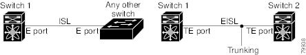
- An industry standard E port can link to other vendor switches and is referred to as inter-switch link (ISL), as shown on the left side of the figure below.
- VSAN trunking enables a link transmitting frames in the EISL format to carry traffic for multiple VSAN . When trunking is operational on an E port, that E port becomes a TE port. EISLs connects only between Cisco switches, as shown on the right side of the figure below.
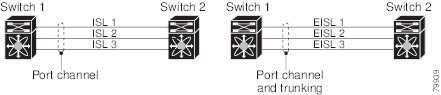
- You can create a SAN port channel with members that are E ports, as shown on the left side of the figure below. In this configuration, the port channel implements a logical ISL (carrying traffic for one VSAN).
- You can create a SAN port channel with members that are TE-ports, as shown on the right side of the figure below. In this configuration, the port channel implements a logical EISL (carrying traffic for multiple VSANs).
- Port channel interfaces can be channeled between the following port sets:
- Trunking permits traffic on multiple VSANs between switches.
- Port channels and trunking can be used between TE ports over EISLs.
Understanding Load Balancing
Load-balancing functionality can be provided using the following methods:
- Flow based—All frames between source and destination follow the same links for a given flow. That is, whichever link is selected for the first exchange of the flow is used for all subsequent exchanges.
- Exchange based—The first frame in an exchange is assigned to a link, and then subsequent frames in the exchange follow the same link. However, subsequent exchanges can use a different link. This method provides finer granularity for load balancing while preserving the order of frames for each exchange.
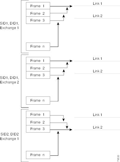
The following figure illustrates how flow-based load balancing works. When the first frame in a flow is received on an interface for forwarding, link 1 is selected. Each subsequent frame in that flow is sent over the same link. No frame in SID1 and DID1 utilizes link 2.
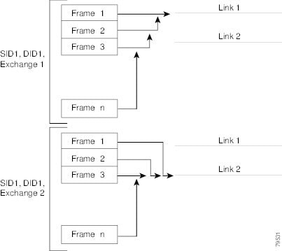
The following figure illustrates how exchange-based load balancing works. When the first frame in an exchange is received for forwarding on an interface, link 1 is chosen by a hash algorithm. All remaining frames in that particular exchange are sent on the same link. For exchange 1, no frame uses link 2. For the next exchange, link 2 is chosen by the hash algorithm. Now all frames in exchange 2 use link 2.
Configuring SAN Port Channels
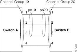
SAN port channels are created with default values. You can change the default configuration just as any other physical interface.
The following figure provides examples of valid SAN port channel configurations.
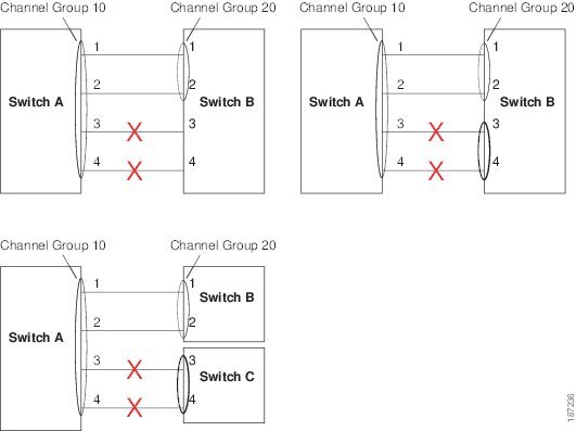
The following figure shows examples of invalid configurations. Assuming that the links are brought up in the 1, 2, 3, 4 sequence, links 3 and 4 will be operationally down as the fabric is misconfigured.
- SAN Port Channel Configuration Guidelines
- Creating a SAN Port Channel
- About Port Channel Modes
- About SAN Port Channel Deletion
SAN Port Channel Configuration Guidelines
Before configuring a SAN port channel, consider the following guidelines:
- Configure the SAN port channel using Fibre Channel ports from both expansion modules to provide increased availability (if one of the expansion modules failed).
- Ensure that one SAN port channel is not connected to different sets of switches. SAN port channels require point-to-point connections between the same set of switches.
- If you misconfigure SAN port channels, you may receive a misconfiguration message. If you receive this message, the port channel’s physical links are disabled because an error has been detected.
- If the following requirements are not met, a SAN port channel error is detected:
- Each switch on either side of a SAN port channel must be connected to the same number of interfaces.
- Each interface must be connected to a corresponding interface on the other side.
- Links in a SAN port channel cannot be changed after the port channel is configured. If you change the links after the port channel is configured, be sure to reconnect the links to interfaces within the port channel and reenable the links. If all three conditions are not met, the faulty link is disabled.
Enter the show interface command for that interface to verify that the SAN port channel is functioning as required.
F and TF Port Channel Guidelines
The guidelines for F and TF port channels are as follows:
- The ports must be in F mode.
- Automatic creation is not supported.
- ON mode is not supported. Only Active-Active mode is supported. By default, the mode is Active on the NPV switches.
- Devices logged in through the F port channel on an MDS switch are not supported in IVR non-NAT configuration. The devices are supported only in IVR NAT configuration.
- Port security rules are enforced only on physical PWWNs at the single link level.
- The name server registration of the N ports logging in through an F port channel will use the FWWN of the port channel interface.
- DPVM configuration is not supported.
- The port channel port VSAN cannot be configured using Dynamic Port VSAN Membership (DPVM).
About Port Channel Modes
You can configure each SAN port channel with a channel group mode parameter to determine the port channel protocol behavior for all member ports in this channel group. The possible values for a channel group mode are as follows:
- On (default)—The member ports only operate as part of a SAN port channel or remain inactive. In this mode, the port channel protocol is not initiated. However, if a port channel protocol frame is received from a peer port, the software indicates its nonnegotiable status. Port channels configured in the On mode require you to explicitly enable and disable the port channel member ports at either end if you add or remove ports from the port channel configuration. You must physically verify that the local and remote ports are connected to each other.
- Active—The member ports initiate port channel protocol negotiation with the peer port(s) regardless of the channel group mode of the peer port. If the peer port, while configured in a channel group, does not support the port channel protocol, or responds with a nonnegotiable status, it will default to the On mode behavior. The Active port channel mode allows automatic recovery without explicitly enabling and disabling the port channel member ports at either end.
NoteA F port channel is supported only in Active Mode.
The table below compares On and Active modes.
Table 1 Channel Group Configuration Differences On Mode
Active Mode
No protocol is exchanged.
A port channel protocol negotiation is performed with the peer ports.
Moves interfaces to the suspended state if its operational values are incompatible with the SAN port channel.
Moves interfaces to the isolated state if its operational values are incompatible with the SAN port channel.
When you add or modify a port channel member port configuration, you must explicitly disable (shut) and enable (no shut) the port channel member ports at either end.
When you add or modify a port channel interface, the SAN port channel automatically recovers.
Port initialization is not synchronized.
There is synchronized startup of all ports in a channel across peer switches.
All misconfigurations are not detected as no protocol is exchanged.
Consistently detect misconfigurations using a port channel protocol.
Transitions misconfigured ports to the suspended state. You must explicitly disable (shut) and enable (no shut) the member ports at either end.
Transitions misconfigured ports to the isolated state to correct the misconfiguration. Once you correct the misconfiguration, the protocol ensures automatic recovery.
This is the default mode.
You must explicitly configure this mode.
Configuring Active Mode SAN Port Channel
ProcedureAbout SAN Port Channel Deletion
When you delete the SAN port channel, the corresponding channel membership is also deleted. All interfaces in the deleted SAN port channel convert to individual physical links. After the SAN port channel is removed, regardless of the mode (active and on) used, the ports at either end are gracefully brought down, indicating that no frames are lost when the interface is going down.
If you delete the SAN port channel for one port, then the individual ports within the deleted SAN port channel retain the compatibility parameter settings (speed, mode, port VSAN, allowed VSAN, and port security). You can explicitly change those settings as required.
Related Tasks
Interfaces in a SAN Port Channel
You can add or remove a physical Fibre Channel interface (or a range of interfaces) to an existing SAN port channel. The compatible parameters on the configuration are mapped to the SAN port channel. Adding an interface to a SAN port channel increases the channel size and bandwidth of the SAN port channel. Removing an interface from a SAN port channel decreases the channel size and bandwidth of the SAN port channel.
Note
Virtual Fibre Channel interfaces cannot be added to SAN port channels.
- About Interface Addition to a SAN Port Channel
- Adding an Interface to a SAN Port Channel
- Forcing an Interface Addition
- About Interface Deletion from a SAN Port Channel
- Deleting an Interface from a SAN Port Channel
About Interface Addition to a SAN Port Channel
You can add a physical interface (or a range of interfaces) to an existing SAN port channel. The compatible parameters on the configuration are mapped to the SAN port channel. Adding an interface to a SAN port channel increases the channel size and bandwidth of the SAN port channel.
After the members are added, regardless of the mode (Active and On) used, the ports at either end are gracefully brought down, indicating that no frames are lost when the interface is going down.
Compatibility Check
A compatibility check ensures that the same parameter settings are used in all physical ports in the channel. Otherwise, they cannot become part of a SAN port channel. The compatibility check is performed before a port is added to the SAN port channel.
The check ensures that the following parameters and settings match at both ends of a SAN port channel:
- Capability parameters (type of interface, Fibre Channel at both ends).
- Administrative compatibility parameters (speed, mode, port VSAN, allowed VSAN, and port security).
- Operational parameters (speed and remote switch’s WWN).
A port addition procedure fails if the capability and administrative parameters in the remote switch are incompatible with the capability and administrative parameters in the local switch. If the compatibility check is successful, the interfaces are operational and the corresponding compatibility parameter settings apply to these interfaces.
Beginning with Cisco NX-OS Release 5.0(2)N2(1), after you enable forcing a port to be added to a channel group by entering the channel-group force command, the following two conditions occur:
Adding an Interface to a SAN Port Channel
ProcedureForcing an Interface Addition
ProcedureYou can force the port configuration to be overwritten by the SAN port channel. In this case, the interface is added to a SAN port channel.
- If you use the default On mode to avoid inconsistent states across switches and to maintain consistency across switches, then the ports shut down. You must explicitly enable those ports again.
- If you use the Active mode, then the port channel ports automatically recover from the addition.
Note
When SAN port channels are created from within an interface, the force option cannot be used.
After the members are forcefully added, regardless of the mode (Active and On) used, the ports at either end are gracefully brought down, indicating that no frames are lost when the interface is going down.
To force the addition of a port to a SAN port channel, perform this task:
Command or Action Purpose
Step 1 switch# configure terminal Enters global configuration mode.
Step 2 switch(config)# interface type slot/port
Enters configuration mode for the specified interface.
Note If this is a QSFP+ GEM, the slot/port syntax is slot/QSFP-module/port.
Step 3 switch(config-if)# channel-group channel-number force
Forces the addition of the interface into the specified channel group. The E port is shut down.
About Interface Deletion from a SAN Port Channel
When a physical interface is deleted from the SAN port channel, the channel membership is automatically updated. If the deleted interface is the last operational interface, then the port channel status is changed to a down state. Deleting an interface from a SAN port channel decreases the channel size and bandwidth of the SAN port channel.
- If you use the default On mode to avoid inconsistent states across switches and to maintain consistency across switches, then the ports shut down. You must explicitly enable those ports again.
- If you use the Active mode, then the port channel ports automatically recover from the deletion.
After the members are deleted, regardless of the mode (Active and On) used, the ports at either end are gracefully brought down, indicating that no frames are lost when the interface is going down.
Deleting an Interface from a SAN Port Channel
ProcedureTo delete a physical interface (or a range of physical interfaces) from a SAN port channel, perform this task:
Command or Action Purpose
Step 1 switch# configure terminal Enters global configuration mode.
Step 2 switch(config)# interface type slot/port
Enters configuration mode for the specified interface.
Note If this is a QSFP+ GEM, the slot/port syntax is slot/QSFP-module/port.
Step 3 switch(config-if)# no channel-group channel-number
Deletes the physical Fibre Channel interface from the specified channel group.
SAN Port Channel Protocol
The switch software provides robust error detection and synchronization capabilities. You can manually configure channel groups, or they can be automatically created. In both cases, the channel groups have the same capability and configurational parameters. Any change in configuration applied to the associated SAN port channel interface is propagated to all members of the channel group.
Cisco SAN switches support a protocol to exchange SAN port channel configurations, which simplifies port channel management with incompatible ISLs. An additional autocreation mode enables ISLs with compatible parameters to automatically form channel groups without manual intervention.
The port channel protocol is enabled by default.
The port channel protocol expands the port channel functional model in Cisco SAN switches. It uses the exchange peer parameters (EPP) services to communicate across peer ports in an ISL. Each switch uses the information received from the peer ports along with its local configuration and operational values to decide if it should be part of a SAN port channel. The protocol ensures that a set of ports are eligible to be part of the same SAN port channel. They are only eligible to be part of the same port channel if all the ports have a compatible partner.
The port channel protocol uses two subprotocols:
- Bringup protocol—Automatically detects misconfigurations so you can correct them. This protocol synchronizes the SAN port channel at both ends so that all frames for a given flow (as identified by the source FC ID, destination FC ID and OX_ID) are carried over the same physical link in both directions. This helps make applications such as write acceleration work for SAN port channels over FCIP links.
- Autocreation protocol—Automatically aggregates compatible ports into a SAN port channel.
- About Channel Group Creation
- Autocreation Guidelines
- Enabling and Configuring Autocreation
- About Manually Configured Channel Groups
- Converting to Manually Configured Channel Groups
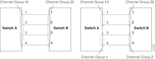
About Channel Group Creation
If channel group autocreation is enabled, ISLs can be configured automatically into channel groups without manual intervention. The following figure shows an example of channel group autocreation.
The first ISL comes up as an individual link. In the example shown in the following figure, this is link A1-B1. When the next link comes up (A2-B2 in the example), the port channel protocol determines if this link is compatible with link A1-B1 and automatically creates channel groups 10 and 20 in the respective switches. Link A3-B3 can join the channel groups (and the port channels) if the respective ports have compatible configurations. Link A4-B4 operates as an individual link, because it is not compatible with the existing member ports in the channel group.
The channel group numbers are assigned dynamically (when the channel group is formed).
The channel group number may change across reboots for the same set of port channels depending on the initialization order of the ports.
The following table identifies the differences between user-configured and auto-configured channel groups.
Table 2 Channel Group Configuration Differences User-Configured Channel Group
Autocreated Channel Group
Manually configured by the user.
Created automatically when compatible links come up between two compatible switches, if channel group autocreation is enabled in all ports at both ends.
Member ports cannot participate in autocreation of channel groups. The autocreation feature cannot be configured.
None of these ports are members of a user-configured channel group.
You can form the SAN port channel with a subset of the ports in the channel group. Incompatible ports remain in a suspended or isolated state depending on the On or Active mode configuration.
All ports included in the channel group participate in the SAN port channel. No member port becomes isolated or suspended; instead, the member port is removed from the channel group when the link is found to be incompatible.
Any administrative configuration made to the SAN port channel is applied to all ports in the channel group, and you can save the configuration for the port channel interface.
Any administrative configuration made to the SAN port channel is applied to all ports in the channel group, but the configurations are saved for the member ports; no configuration is saved for the port channel interface. You can explicitly convert this channel group, if required.
You can remove any channel group and add members to a channel group.
You cannot remove a channel group. You cannot add members to the channel group or remove members. The channel group is removed when no member ports exist.
Autocreation Guidelines
When using the autocreation protocol, follow these guidelines:
- A port is not allowed to be configured as part of a SAN port channel when the autocreation feature is enabled. These two configurations are mutually exclusive.
- Autocreation must be enabled in both the local and peer ports to negotiate a SAN port channel.
- Aggregation occurs in one of two ways:
- Newly created SAN port channels are allocated from the maximum possible port channel number in a decreasing order based on availability. If all port channel numbers are used up, aggregation is not allowed.
- You cannot change the membership or delete an autocreated SAN port channel.
- When you disable autocreation, all member ports are removed from the autocreated SAN port channel.
- Once the last member is removed from an autocreated SAN port channel, the channel is automatically deleted and the number is released for reuse.
- An autocreated SAN port channel is not persistent through a reboot. An autocreated SAN port channel can be manually configured to appear the same as a persistent SAN port channel. Once the SAN port channel is made persistent, the autocreation feature is disabled in all member ports.
- You can enable or disable the autocreation feature on a per-port basis or for all ports in the switch. When this configuration is enabled, the channel group mode is assumed to be active. The default for this task is disabled.
- If autocreation of channel groups is enabled for an interface, you must first disable autocreation before downgrading to earlier software versions or before configuring the interface in a manually configured channel group.
Tip
When enabling autocreation in any Cisco Nexus device, we recommend that you retain at least one interconnected port between the switches without any autocreation configuration. If all ports between two switches are configured with the autocreation feature at the same time, a possible traffic disruption may occur between these two switches as ports are automatically disabled and reenabled when they are added to an autocreated SAN port channel.
Enabling and Configuring Autocreation
Procedure
Command or Action Purpose
Step 1 switch# configure terminal Enters global configuration mode.
Step 2 switch(config)# interface type slot/port
Enters configuration mode for the specified interface.
Note If this is a QSFP+ GEM, the slot/port syntax is slot/QSFP-module/port.
Step 3 switch(config- if)# channel-group auto
Automatically creates the channel group for the selected interface(s).
Step 4 switch(config- if)# no channel-group auto
Disables the autocreation of channel groups for this interface, even if the system default configuration may have autocreation enabled.
About Manually Configured Channel Groups
A user-configured channel group cannot be converted to an autocreated channel group. However, you can convert an autocreated channel group to a manual channel group. This task is irreversible. The channel group number does not change, but the member ports operate according to the properties of the manually configured channel group, and channel group autocreation is implicitly disabled for all the member ports.
If you enable persistence, be sure to enable it at both ends of the SAN port channel.
Example Port Channel Configurations
This section shows examples on how to configure an F port channel in shared mode and how to bring up the link between F ports on the NPIV core switches and NP ports on the NPV switches. Before you configure the F port channel, ensure that F port trunking, F port channeling, and NPIV are enabled.
This example shows how to create the port channel:
switch(config)# interface port-channel 2switch(config-if)# switchport mode Fswitch(config-if)# switchport dedicatedswitch(config-if)# channel mode activeswitch(config-if)# exitThis example shows how to configure the port channel member interfaces on the core switch in dedicated mode:
switch(config)# interface fc1/4-6switch(config-if)# shutswitch(config-if)# switchport mode Fswitch(config-if)# switchport speed 4000switch(config-if)# switchport rate-mode dedicatedswitch(config-if)# switchport trunk mode onswitch(config-if)# channel-group 2switch(config-if)# no shutswitch(config-if)# exitThis example shows how to create the port channel in dedicated mode on the NPV switch:
switch(config)# interface san-port-channel 2switch(config-if)# switchport mode NPswitch(config-if)# no shutswitch(config-if)# exitThis example shows how to configure the port channel member interfaces on the NPV switch:
switch(config)# interface fc2/1-2switch(config-if)# shutswitch(config-if)# switchport mode NPswitch(config-if)# switchport trunk mode onswitch(config-if)# channel-group 2switch(config-if)# no shutswitch(config-if)# exitVerifying SAN Port Channel Configuration
ProcedureYou can view specific information about existing SAN port channels at any time from EXEC mode. The following show commands provide further details on existing SAN port channels.
The show san-port-channel summary command displays a summary of SAN port channels within the switch. A one-line summary of each SAN port channel provides the administrative state, the operational state, the number of attached and active interfaces (up), and the first operational port (FOP), which is the primary operational interface selected in the SAN port channel to carry control-plane traffic (no load-balancing). The FOP is the first port that comes up in a SAN port channel and can change if the port goes down. The FOP is also identified by an asterisk ( * ).
To display VSAN configuration information, perform one of the following tasks:
Command or Action Purpose
Step 1 switch# show san-port-channel summary | database | consistency [ details ] | usage | compatibility-parameters
Displays SAN port channel information.
Step 2 switch# show san-port-channel database interface san-port-channel channel-number
Displays information for the specified SAN port channel.
Step 3 switch# switch# show interface fc slot/port
Displays VSAN configuration information for the specified Fibre Channel interface.
Note If this is a QSFP+ GEM, the slot/port syntax is slot/QSFP-module/port.
Example of Verification Commands
The following example shows how to display a summary of SAN port channel information:
switch# show san-port-channel summary
------------------------------------------------------------------------------
Interface                 Total Ports        Oper Ports        First Oper Port
------------------------------------------------------------------------------
san-port-channel 7              2                 0                  --
san-port-channel 8              2                 0                  --
san-port-channel 9              2                 2
The following example shows how to display SAN port channel consistency:
switch# show san-port-channel consistency
Database is consistent
The following example shows how to display details of the used and unused port channel numbers:
switch# show san-port-channel usage
Totally 3 port-channel numbers used
===================================
Used  :   77 - 79
Unused:   1 - 76 , 80 - 256
Autocreated SAN port channels are indicated explicitly to help differentiate them from the manually created SAN port channels. The following example shows how to display an autocreated port channel:
switch# show interface fc2/1
fc2/1 is trunking
    Hardware is Fibre Channel, FCOT is short wave laser
    Port WWN is 20:0a:00:0b:5f:3b:fe:80
    ...
    Receive data field Size is 2112
    Port-channel auto creation is enabled

Belongs to port-channel 123
...