-
Cisco Nexus 5500 Series NX-OS SAN Switching Configuration Guide, Release 7.x
-
Preface
-
Overview
-
Configuring Fibre Channel Interfaces
-
Configuring Fibre Channel Domain Parameters
-
Configuring N Port Virtualization
-
Configuring FCoE NPV
-
Configuring VSAN Trunking
-
Configuring SAN Port Channels
-
Configuring and Managing VSANs
-
Configuring and Managing Zones
-
Distributing Device Alias Services
-
Configuring Fibre Channel Routing Services and Protocols
-
Managing FLOGI, Name Server, FDMI, and RSCN Databases
-
Discovering SCSI Targets
-
Configuring iSCSI TLV
-
Advanced Fibre Channel Features
-
Configuring FC-SP and DHCHAP
-
Configuring Port Security
-
Configuring Fabric Binding
-
Configuring Fabric Configuration Servers
-
Configuring Port Tracking
-
Index
-
 Feedback
Contents
- Configuring FCoE NPV
- Information About FCoE NPV
- FCoE NPV Model
- Mapping Requirements
- Port Requirements
- NPV Features
- vPC Topologies
- Supported and Unsupported Topologies
- Guidelines and Limitations
- FCoE NPV Configuration Limits
- Default Settings
- Enabling FCoE and Enabling NPV
- Enabling FCoE NPV
- Configuring NPV Ports for FCoE NPV
- Verifying FCoE NPV Configuration
- Configuration Examples for FCoE NPV
Configuring FCoE NPV
This chapter contains the following sections:
- Information About FCoE NPV
- FCoE NPV Model
- Mapping Requirements
- Port Requirements
- NPV Features
- vPC Topologies
- Supported and Unsupported Topologies
- Guidelines and Limitations
- Default Settings
- Enabling FCoE and Enabling NPV
- Enabling FCoE NPV
- Configuring NPV Ports for FCoE NPV
- Verifying FCoE NPV Configuration
- Configuration Examples for FCoE NPV
Information About FCoE NPV
FCoE NPV is supported on the Cisco Nexus devices. The FCoE NPV feature is an enhanced form of FIP snooping that provides a secure method to connect FCoE-capable hosts to an FCoE-capable FCoE forwarder (FCF) switch. The FCoE NPV feature provides the following benefits:
- FCoE NPV does not have the management and troubleshooting issues that are inherent to managing hosts remotely at the FCF.
- FCoE NPV implements FIP snooping as an extension to the NPV function while retaining the traffic-engineering, vsan-management, administration and trouble-shooting aspects of NPV.
- FCoE NPV and NPV together allow communication through FC and FCoE ports at the same time. This provides a smooth transition when moving from FC to FCoE topologies.
You can enable FCoE NPV by choosing one of the following methods:
- Enable FCoE and then enable NPV—This method requires that you enable FCoE first using the feature fcoe command and then you enable NPV by using the feature npv command. When FCoE is enabled, the default mode of operation is FC switching and when you enable NPV, the mode changes to NPV mode. Switching to NPV mode automatically performs a write erase and reloads the system. After the reload, the system comes up in NPV mode. To exit NPV mode and return to FC switching mode, enter the no feature npv command. Exiting NPV mode also triggers a write erase and a switch reload. This method requires the Storage Protocols Services Package (FC_FEATURES_PKG) license .
- Enable FCoE NPV—When you enable FCoE NPV using the feature fcoe-npv command, the mode changes to NPV. When you use this method, a write erase and reload does not occur. This method requires a separate license package (FCOE_NPV_PKG). This license is also included in the Storage Protocol Services License.
Method License Write Erase Reload Enable FCoE and then Enable NPV Storage Protocols Services Package (FC_FEATURES_PKG) Yes Yes Enable FCoE NPV (FCOE_NPV_PKG) No No Interoperability with FCoE-Capable Switches
The Cisco Nexus device interoperates with the following FCoE-capable switches:For detailed information about switch interoperability, see the Cisco Data Center Interoperability Support Matrix.
Licensing
The following table shows the licensing requirements for FCoE NPV:
Product License Requirement NX-OS FCoE NPV requires a separate license (FCOE_NPV_PKG). The FCoE NPV license is also included in the Storage Protocol Services License.
FCoE and NPV require the Storage Protocols Services Package (FC_FEATURES_PKG).
For detailed information about features that require licensing and Cisco NX-OS license installation, see the Cisco NX-OS Licensing Guide.
For information about troubleshooting licensing issues, see the Troubleshooting Guide for your device.
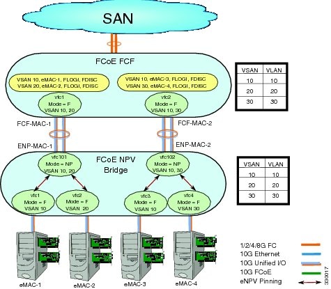
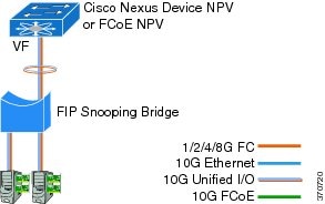
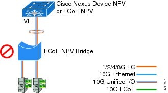
FCoE NPV Model
The following figure shows the FCoE NPV bridge connecting hosts and FCFs. From a control plane perspective, FCoE NPV performs proxy functions towards the FCF and the hosts in order to load balance logins from the hosts evenly across the available FCF uplink ports. An FCoE NPV bridge is VSAN-aware and capable of assigning VSANs to the hosts.
Mapping Requirements
VSANs and VLAN-VSAN Mapping
VSANs from the hosts must be created and for each VSAN, a dedicated VLAN must also be created and mapped. The mapped VLAN is used to carry FIP and FCoE traffic for the corresponding VSAN. The VLAN-VSAN mapping must be configured consistently in the entire fabric. The Cisco Nexus device supports 32 VSANs.
Port Requirements
VF Ports
For each host directly connected over Ethernet interfaces on the FCoE NPV bridge, a virtual Fibre Channel (vFC) interface must be created and bound to the Ethernet interface. By default, the vFC interface is configured in the F mode (VF port).
The VF port must be configured with the following parameters:VNP Ports
Connectivity from an FCoE NPV bridge to the FCF is only supported over point-to-point links. These links can be individual Ethernet interfaces or members of an Ethernet port channel interface. For each FCF connected Ethernet interfaces, a vFC interface must be created and bound to the Ethernet interface. These vFC interfaces must be configured as VNP ports. On the VNP port, an FCoE NPV bridge emulates an FCoE-capable host with multiple enodes, each with a unique enode MAC address. A VNP port interface binding to MAC address is not supported. By default, the VNP port is enabled in trunk mode. Multiple VSANs can be configured on the VNP port. The FCoE VLANs that correspond to the VNP port VSANs must be configured on the bound Ethernet interface.
NoteThe spanning-tree protocol (STP) is automatically disabled in the FCoE VLAN on the interfaces that the VNP port are bound to.
vPC Topologies
When VNP ports are configured vPC topologies between an FCoE NPV bridge and an FCF, the following limitations apply:
- vPC spanning multiple FCFs in the same SAN fabric is not supported.
- For LAN traffic, dedicated links must be used for FCoE VLANs between the FCoE NPV bridge and the FCF connected over a vPC.
- FCoE VLANs must not be configured on the inter-switch vPC interfaces.
- VF port binding to a vPC member port is not supported for an inter-switch vPC.
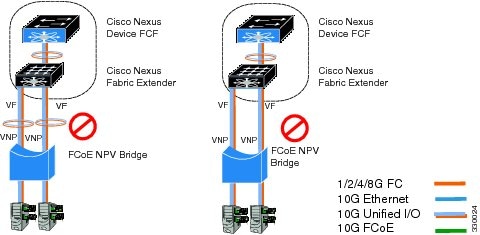
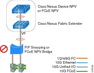
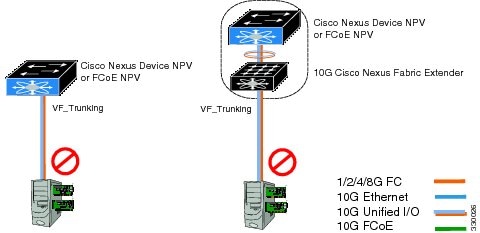
Supported and Unsupported Topologies
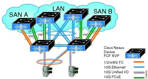
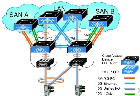
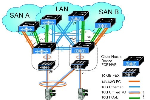
FCoE NPV supports the following topologies:
Figure 3. Cisco Nexus Device As An FCoE NPV Device Connected to a Cisco Nexus Device Over A Non- vPC Port ChannelFigure 4. Cisco Nexus Device As An FCoE NPV Device Connected Over a vPC To Another Cisco Nexus DeviceFigure 5. Cisco Nexus Device With A 10GB Fabric Extender As An FCoE NPV Device Connected to a Cisco Nexus Device Over A Non- vPC Port ChannelFigure 6. Cisco Nexus Device With A 10GB Fabric Extender as an FCoE NPV Device Connected Over a vPC to Another Cisco Nexus DeviceGuidelines and Limitations
The FCoE NPV feature has the following configuration guidelines and limitations:
- When FCoE NPV mode is configured on a switch, the FCoE feature cannot be enabled. A warning is displayed to reload the system first in order to enable FCoE.
The FCoE NPV feature has the following upgrade and downgrade guidelines and limitations:
- You can not perform an in-service software downgrade (ISSD) to Cisco NX-OS Release 5.0(3)N1(1) or an earlier release if FCoE NPV is enabled and if VNP ports are configured.
- A warning is displayed if an ISSD is performed to Cisco NX-OS Release 5.0(3)N1(1) or an earlier release when FCoE NPV is enabled but VNP ports are not configured.
- Before performing an ISSU on an FCoE NPV bridge, use the disable-fka command to disable the timeout value check (FKA check) on the core switch.
FCoE NPV Configuration Limits
The following table lists the FCoE configuration limits over Ethernet, Ethernet port channel, and virtual Ethernet interfaces.
Table 1 VNP Port Configuration Limits Interface Type Cisco Nexus 5500 Platform Cisco Nexus 2000 Series (10G interfaces) VNP port bound to Ethernet interface
16 VNP ports
Not Supported
VNP port bound to Ethernet port channel interface
16 VNP ports
Not Supported
VNP port bound to virtual Ethernet (vEth) interface
Not Supported
Not Supported
The configuration limits guidelines are as follows:
- The number of VF port and VN port interfaces that can be supported between a given FCF and an FCoE NPV bridge also depends on the FCF to MAC advertising capability of the FCF:
- If an FCF advertises the same FCF-MAC address over all of its interfaces, then the FCoE NPV bridge can connect to it over one VNP Port. In this scenario, we recommend that one port channel interface be used for redundancy.
- If an FCF advertises multiple FCF-MAC addresses, then the limits in the previous table apply. For additional information, see the best practices recommendations for the FCF switch.
- The total number of supported VSANs is 31 (excluding the EVFP VSAN).
- The total number of supported FCIDs is 2048.
Enabling FCoE and Enabling NPV
You can enable FCoE first and then enable NPV. This method requires the full Storage Services License. A write erase reload occurs when this method is used. This method allows both FCoE and FC upstream and host NPV connections. You must also configure class-fcoe in all QoS policy types.
Enabling FCoE NPV
ProcedureYou can enable FCoE NPV using the feature fcoe-npv command. We recommend this method in topologies that include all FCoE connections. A write erase reload does not occur when you use this method and a storage service license is not required. Enabling FCoE NPV using the feature fcoe-npv command requires an installed FCOE_NPV_PKG license.
This example shows how to enable FCoE NPV using the feature fcoe-npv command.
switch# configure terminal
switch(config)# feature fcoe-npv
FCoE NPV license checked out successfully
fc_plugin extracted successfully
FC plugin loaded successfully
FCoE manager enabled successfully
FCoE NPV enabled on all modules successfully
This example shows how to enable FCoE NPV using the feature fcoe and feature npv commands.
switch# configure terminal
switch(config)# feature fcoe
switch(config)# feature npv
Configuring NPV Ports for FCoE NPV
You can configure NVP port for FCoE NPV.
- Create a vFC port.
switch# config t switch(config)# interface vfc 20 switch(config-if)#- Bind the vFC to an Ethernet port.
switch(config-if)# bind interface ethernet 1/20 switch(config-if)#- Set the port mode to NP.
switch(config-if)# switchport mode NP switch(config-if)#- Bring up the port:
switch(config-if)# interface vfc 20no shutdown
switch(config-if)#
Verifying FCoE NPV Configuration
To display FCoE NPV configuration information, perform one of the following tasks:
Command Purpose show fcoe database
Displays information about the FCoE database. show interface Ethernet x/y fcoe
Displays FCoE information for a specified Ethernet interface including the following:
show interface vfc x
Displays information about the specified vFC interface including attributes and status.
show npv status
Displays the status of the NPV configuration including information about VNP ports.
show fcoe-npv issu-impact
Displays the impact of FCoE NPV on an ISSU.
show running-config fcoe_mgr
Displays the running configuration information about FCoE.
show startup-config fcoe_mgr
Displays the startup configuration information about FCoE.
show tech-support fcoe
Displays troubleshooting information about FCoE.
show npv flogi-table
Displays information about N port virtualization (NPV) fabric login (FLOGI) session
show fcoe
Displays the status of Fibre Channel over Ethernet (FCoE) configurations.
For detailed information about the fields in the output from these commands, refer to the command reference for your device.
Configuration Examples for FCoE NPV
This example shows how to enable FCoE NPV, LACP, QoS for no drop queuing, and VLAN/VSAN mapping:
switch# config t
switch(config)# feature fcoe-npv
FCoE NPV license checked out successfully
fc_plugin extracted successfully
FC plugin loaded successfully
FCoE manager enabled successfully
FCoE NPV enabled on all modules successfully

switch(config)# feature lacp

switch# config t
switch(config)# system qos
switch(config-sys-qos)# service-policy type qos input fcoe-default-in-policy
switch(config-sys-qos)# service-policy type queuing input fcoe-default-in-policy
switch(config-sys-qos)# service-policy type queuing output fcoe-default-out-policy
switch(config-sys-qos)# service-policy type network-qos fcoe-default-nq-policy

switch(config)# vsan database
switch(config-vsan-db)# vsan 50-51
switch(config-vsan-db)# vlan 50
switch(config-vlan)# fcoe vsan 50
switch(config-vlan)# vlan 51
switch(config-vlan)# fcoe vsan 51

This example shows a summary of the interface configuration information for trunked NP ports:
switch# show interface brief | grep TNP
fc2/5      400    NP     on      trunking         swl    TNP     2    --
fc2/6      400    NP     on      trunking         swl    TNP     2    --

vfc130     1      NP     on      trunking         --     TNP     auto --
switch#
This example shows the running configuration information about FCoE:
switch# show running-config fcoe_mgr

!Command: show running-config fcoe_mgr
!Time: Wed Jan  20 21:59:39 2013

version 6.0(2)N1(1)

interface vfc1
  bind interface Ethernet1/19

interface vfc2
  bind interface Ethernet1/2

interface vfc90
  bind interface Ethernet1/9

interface vfc100
  bind interface Ethernet1/10

interface vfc110
  bind interface port-channel110

interface vfc111
  bind interface Ethernet1/11

interface vfc120
  bind interface port-channel120

interface vfc130
  bind interface port-channel130

interface vfc177
  bind interface Ethernet1/7
fcoe fka-adv-period 16
This example shows the FCoE VLAN to VSAN mappings:
switch# show vlan fcoe

Original VLAN ID        Translated VSAN ID      Association State
----------------        ------------------      -----------------

      400                       400              Operational
      20                        20               Operational
      100                       100              Operational
      500                       500              Operational
      200                       200              Operational
      300                       300              Operational
This example shows the information about the vFC 130 interface including attributes and status:
switch# show interface vfc 130
vfc130 is trunking (Not all VSANs UP on the trunk)
    Bound interface is port-channel130
    Hardware is Virtual Fibre Channel
    Port WWN is 20:81:00:05:9b:74:bd:bf
    Admin port mode is NP, trunk mode is on
    snmp link state traps are enabled
    Port mode is TNP
    Port vsan is 1
    Trunk vsans (admin allowed and active) (1,20,100,200,300,400,500)
    Trunk vsans (up)                       (500)
    Trunk vsans (isolated)                 ()
    Trunk vsans (initializing)             (1,20,100,200,300,400)
    1 minute input rate 0 bits/sec, 0 bytes/sec, 0 frames/sec
    1 minute output rate 0 bits/sec, 0 bytes/sec, 0 frames/sec
      15 frames input, 2276 bytes
        0 discards, 0 errors
      7 frames output, 1004 bytes
        0 discards, 0 errors
    last clearing of "show interface" counters Tue May 31 20:56:41 2011

    Interface last changed at Wed Jun  1 21:53:08 2011
This example shows the information about the vFC 1 interface including attributes and status:
switch# show interface vfc 1
vfc1 is trunking (Not all VSANs UP on the trunk)
    Bound interface is Ethernet1/19
    Hardware is Virtual Fibre Channel
    Port WWN is 20:00:00:05:9b:74:bd:bf
    Admin port mode is F, trunk mode is on
    snmp link state traps are enabled
    Port mode is TF
    Port vsan is 20
    Trunk vsans (admin allowed and active) (1,20,100,200,300,400,500)
    Trunk vsans (up)                       (20)
    Trunk vsans (isolated)                 ()
    Trunk vsans (initializing)             (1,100,200,300,400,500)
    1 minute input rate 0 bits/sec, 0 bytes/sec, 0 frames/sec
    1 minute output rate 0 bits/sec, 0 bytes/sec, 0 frames/sec
      355278397 frames input, 573433988904 bytes
        0 discards, 0 errors
      391579316 frames output, 572319570200 bytes
        0 discards, 0 errors
    last clearing of "show interface" counters Tue May 31 20:56:41 2011

    Interface last changed at Wed Jun  1 20:25:36 2011
This example shows the information about the NPV FLOGI session:
switch# show npv flogi-table
--------------------------------------------------------------------------------
SERVER                                                                  EXTERNAL
INTERFACE VSAN FCID             PORT NAME               NODE NAME       INTERFACE
--------------------------------------------------------------------------------
vfc1      20   0x670000 21:01:00:1b:32:2a:e5:b8 20:01:00:1b:32:2a:e5:b8 fc2/6

Total number of flogi = 1.
This example shows the status of the NPV configuration including information about VNP ports:
switch# show npv status

npiv is enabled

disruptive load balancing is disabled

External Interfaces:
====================
  Interface:  fc2/5, State: Trunking
        VSAN:    1, State: Up
        VSAN:  200, State: Up
        VSAN:  400, State: Up
        VSAN:   20, State: Up
        VSAN:  100, State: Up
        VSAN:  300, State: Up
        VSAN:  500, State: Up, FCID: 0xa10000
  Interface:  fc2/6, State: Trunking
        VSAN:    1, State: Up
        VSAN:  200, State: Up
        VSAN:  400, State: Up
        VSAN:   20, State: Up
        VSAN:  100, State: Up
        VSAN:  300, State: Up
        VSAN:  500, State: Up, FCID: 0xa10001
  Interface: vfc90,  State: Down
  Interface: vfc100, State: Down
  Interface: vfc110, State: Down
  Interface: vfc111, State: Down
  Interface: vfc120, State: Down
  Interface: vfc130, State: Trunking
        VSAN:    1, State: Waiting For VSAN Up
        VSAN:  200, State: Up
        VSAN:  400, State: Up
        VSAN:  100, State: Up
        VSAN:  300, State: Up
        VSAN:  500, State: Up, FCID: 0xa10002

  Number of External Interfaces: 8

Server Interfaces:
==================
  Interface:   vfc1, VSAN:   20, State: Up
  Interface:   vfc2, VSAN: 4094, State: Down
  Interface:   vfc3, VSAN: 4094, State: Down
  Interface: vfc5000, VSAN: 4094, State: Down
  Interface: vfc6000, VSAN: 4094, State: Down
  Interface: vfc7000, VSAN: 4094, State: Down
  Interface: vfc8090, VSAN: 4094, State: Down
  Interface: vfc8191, VSAN: 4094, State: Down

  Number of Server Interfaces: 8
This example shows the running configuration of port channel 130:
switch# show running-config interface port-channel 130

!Command: show running-config interface port-channel130
!Time: Wed Jan  30 22:01:05 2013

version 6.0(2)N1(1)

interface port-channel130
  switchport mode trunk
  switchport trunk native vlan 2
  no negotiate auto
This example shows the impact of FCoE NPV on an ISSU:
switch# show fcoe-npv issu-impact
show fcoe-npv issu-impact
-------------------------

Please make sure to enable "disable-fka" on all logged in VFCs
Please increase the FKA duration to 60 seconds on FCF


Active VNP ports with no disable-fka set
----------------------------------------

vfc90
vfc100
vfc110
vfc111
vfc120
vfc130

ISSU downgrade not supported as feature fcoe-npv is enabled
switch#