-
Cisco Nexus 5500 Series NX-OS SAN Switching Configuration Guide, Release 7.x
-
Preface
-
Overview
-
Configuring Fibre Channel Interfaces
-
Configuring Fibre Channel Domain Parameters
-
Configuring N Port Virtualization
-
Configuring FCoE NPV
-
Configuring VSAN Trunking
-
Configuring SAN Port Channels
-
Configuring and Managing VSANs
-
Configuring and Managing Zones
-
Distributing Device Alias Services
-
Configuring Fibre Channel Routing Services and Protocols
-
Managing FLOGI, Name Server, FDMI, and RSCN Databases
-
Discovering SCSI Targets
-
Configuring iSCSI TLV
-
Advanced Fibre Channel Features
-
Configuring FC-SP and DHCHAP
-
Configuring Port Security
-
Configuring Fabric Binding
-
Configuring Fabric Configuration Servers
-
Configuring Port Tracking
-
Index
-
 Feedback
Contents
- Configuring N Port Virtualization
- Configuring N Port Virtualization
- Information About NPV
- NPV Overview
- NPV Mode
- Server Interfaces
- NP Uplinks
- FLOGI Operation
- NPV Traffic Management
- Automatic Uplink Selection
- Traffic Maps
- Disruptive Load Balancing
- NPV Traffic Management Guidelines
- NPV Guidelines and Limitations
- Configuring NPV
- Enabling NPV
- Configuring NPV Interfaces
- Configuring an NP Interface
- Configuring a Server Interface
- Configuring NPV Traffic Management
- Configuring NPV Traffic Maps
- Enabling Disruptive Load Balancing
- Verifying NPV
- Verifying NPV Examples
- Verifying NPV Traffic Management
Configuring N Port Virtualization
This chapter contains the following sections:
Configuring N Port Virtualization
Information About NPV
NPV Overview
By default, Cisco Nexus devices switches operate in fabric mode. In this mode, the switch provides standard Fibre Channel switching capability and features.
In fabric mode, each switch that joins a SAN is assigned a domain ID. Each SAN (or VSAN) supports a maximum of 239 domain IDs, so the SAN has a limit of 239 switches. In a SAN topology with a large number of edge switches, the SAN may need to grow beyond this limit. NPV alleviates the domain ID limit by sharing the domain ID of the core switch among multiple edge switches.
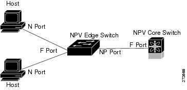
In NPV mode, the edge switch relays all traffic from server-side ports to the core switch. The core switch provides F port functionality (such as login and port security) and all the Fibre Channel switching capabilities.
The edge switch appears as a Fibre Channel host to the core switch and as a regular Fibre Channel switch to its connected devices.
The following figure shows an interface-level view of an NPV configuration.
NPV Mode
In NPV mode, the edge switch relays all traffic to the core switch, which provides the Fibre Channel switching capabilities. The edge switch shares the domain ID of the core switch.
To convert a switch into NPV mode, you set the NPV feature to enabled. This configuration command automatically triggers a switch reboot. You cannot configure NPV mode on a per-interface basis. NPV mode applies to the entire switch.
In NPV mode, a subset of fabric mode CLI commands and functionality is supported. For example, commands related to fabric login and name server registration are not required on the edge switch, because these functions are provided in the core switch. To display the fabric login and name server registration databases, you must enter the show flogi database and show fcns database commands on the core switch.
Server Interfaces
Server interfaces are F ports on the edge switch that connect to the servers. A server interface may support multiple end devices by enabling the N port identifier virtualization (NPIV) feature. NPIV provides a means to assign multiple FC IDs to a single N port, which allows the server to assign unique FC IDs to different applications.
Note
To use NPIV, enable the NPIV feature and reinitialize the server interfaces that will support multiple devices.
Server interfaces are automatically distributed among the NP uplinks to the core switch. All of the end devices connected to a server interface are mapped to the same NP uplink.
In Cisco Nexus devices, server interfaces can be physical or virtual Fibre Channel interfaces.
Related Information
NP Uplinks
All interfaces from the edge switch to the core switch are configured as proxy N ports (NP ports).
An NP uplink is a connection from an NP port on the edge switch to an F port on the core switch. When an NP uplink is established, the edge switch sends a fabric login message (FLOGI) to the core switch, and then (if the FLOGI is successful) it registers itself with the name server on the core switch. Subsequent FLOGIs from end devices connected to this NP uplink are converted to fabric discovery messages (FDISCs).
Note
In the switch CLI configuration commands and output displays, NP uplinks are called External Interfaces.
In Cisco Nexus devices, NP uplink interfaces must be native Fibre Channel interfaces.
Related Concepts
FLOGI Operation
When an NP port becomes operational, the switch first logs itself in to the core switch by sending a FLOGI request (using the port WWN of the NP port).
After completing the FLOGI request, the switch registers itself with the fabric name server on the core switch (using the symbolic port name of the NP port and the IP address of the edge switch).
The following table identifies port and node names in the edge switch used in NPV mode.
Table 1 Edge Switch FLOGI Parameters Parameter
Derived From
pWWN
The fWWN of the NP port on the edge switch.
nWWN
The VSAN-based sWWN of the edge switch.
symbolic port name
The edge switch name and NP port interface string.
Note If no switch name is available, the output will read "switch." For example, switch: fc 1/5.
IP address
The IP address of the edge switch.
symbolic node name
The edge switch name.
NoteThe buffer-to-buffer state change number (BB-SCN) of internal FLOGIs on an NP port is always set to zero. The BB_SCN is supported by the F port on the edge switch.
We do not recommend using fWWN-based zoning on the edge switch for the following reasons:
- Zoning is not enforced at the edge switch (rather, it is enforced on the core switch).
- Multiple devices attached to an edge switch log in through the same F port on the core, so they cannot be separated into different zones.
- The same device might log in using different fWWNs on the core switch (depending on the NPV link it uses) and may need to be zoned using different fWWNs.
Related Concepts
NPV Traffic Management
Automatic Uplink Selection
NPV supports automatic selection of NP uplinks. When a server interface is brought up, the NP uplink interface with the minimum load is selected from the available NP uplinks in the same VSAN as the server interface.
When a new NP uplink interface becomes operational, the existing load is not redistributed automatically to include the newly available uplink. Server interfaces that become operational after the NP uplink can select the new NP uplink.
Traffic Maps
In Release 4.0(1a)N2(1) and later software releases, NPV supports traffic maps. A traffic map allows you to specify the NP uplinks that a server interface can use to connect to the core switches.
Note
When an NPV traffic map is configured for a server interface, the server interface must select only from the NP uplinks in its traffic map. If none of the specified NP uplinks are operational, the server remains in a non-operational state.
The NPV traffic map feature provides the following benefits:
- Facilitates traffic engineering by allowing configuration of a fixed set of NP uplinks for a specific server interface (or range of server interfaces).
- Ensures correct operation of the persistent FC ID feature, because a server interface will always connect to the same NP uplink (or one of a specified set of NP uplinks) after an interface reinitialization or switch reboot.
Disruptive Load Balancing
In Release 4.0(0)N1(2a) and later software releases, NPV supports disruptive load balancing. When disruptive load balancing is enabled, NPV redistributes the server interfaces across all available NP uplinks when a new NP uplink becomes operational. To move a server interface from one NP uplink to another NP uplink, NPV forces reinitialization of the server interface so that the server performs a new login to the core switch.
Only server interfaces that are moved to a different uplink are reinitialized. A system message is generated for each server interface that is moved.
Note
Redistributing a server interface causes traffic disruption to the attached end devices.
To avoid disruption of server traffic, you should enable this feature only after adding a new NP uplink, and then disable it again after the server interfaces have been redistributed.
If disruptive load balancing is not enabled, you can manually reinitialize some or all of the server interfaces to distribute server traffic to new NP uplink interfaces.
NPV Traffic Management Guidelines
When deploying NPV traffic management, follow these guidelines:
- Use NPV traffic management only when automatic traffic engineering does not meet your network requirements.
- You do not need to configure traffic maps for all server interfaces. By default, NPV will use automatic traffic management.
- Server interfaces configured to use a set of NP uplink interfaces cannot use any other available NP uplink interfaces, even if none of the configured interfaces are available.
- When disruptive load balancing is enabled, a server interface may be moved from one NP uplink to another NP uplink. Moving between NP uplink interfaces requires NPV to relogin to the core switch, causing traffic disruption.
- To link a set of servers to a specific core switch, associate the server interfaces with a set of NP uplink interfaces that all connect to that core switch.
- Configure Persistent FC IDs on the core switch and use the Traffic Map feature to direct server interface traffic onto NP uplinks that all connect to the associated core switch.
NPV Guidelines and Limitations
When configuring NPV, note the following guidelines and limitations:
- In-order data delivery is not required in NPV mode because the exchange between two end devices always takes the same uplink from the edge switch to the core. Upstream of the edge switch, core switches will enforce in-order delivery if configured.
- You can configure zoning for end devices that are connected to edge switches using all available member types on the core switch. For fWWN, sWWN, domain, or port-based zoning, use the fWWN, sWWN, domain, or port of the core switch in the configuration commands.
- Port tracking is not supported in NPV mode.
- Port security is supported on the core switch for devices logged in through the NPV switch. Port security is enabled on the core switch on a per-interface basis. To enable port security on the core switch for devices that log in through an NPV switch, you must adhere to the following requirements:
- Edge switches can connect to multiple core switches. In other words, different NP ports can be connected to different core switches.
- NPV uses a load-balancing algorithm to automatically assign end devices in a VSAN to one of the NP uplinks (in the same VSAN) upon initial login. If there are multiple NP uplinks in the same VSAN, you cannot assign an end device to a specific NP uplink.
- If a server interface goes down and then returns to service, the interface is not guaranteed to be assigned to the same NP uplink.
- The server interface is only operational when its assigned NP uplink is operational.
- Servers can be connected to the switch when in NPV mode.
- Targets can not be connected to the switch when in NPV mode.
- Fibre Channel switching is not performed in the edge switch; all traffic is switched in the core switch.
- NPV supports NPIV-capable module servers. This capability is called nested NPIV.
- Only F, NP, and SD ports are supported in NPV mode.
Configuring NPV
Enabling NPV
ProcedureWhen you enable NPV, the system configuration is erased and the switch reboots.
Note
We recommend that you save your current configuration either in boot flash memory or to a TFTP server before you enable NPV.
To enable NPV, perform this task:
Configuring NPV Interfaces
After you enable NPV, you should configure the NP uplink interfaces and the server interfaces.
Configuring an NP Interface
ProcedureAfter you enable NPV, you should configure the NP uplink interfaces and the server interfaces. To configure an NP uplink interface, perform this task:
To configure a server interface, perform this task:
Command or Action Purpose
Step 1 switch# configure terminal Enters global configuration mode.
Step 2 switch(config)# interface fc slot/port
Selects an interface that will be connected to the core NPV switch.
Note If this is a QSFP+ GEM, the slot/port syntax is slot/QSFP-module/port.
Step 3 switch(config-if)# switchport mode NP
Configures the interface as an NP port.
Step 4 switch(config-if)# no shutdown
Brings up the interface.
Configuring a Server Interface
Procedure
Command or Action Purpose
Step 1 switch# configure terminal Enters global configuration mode.
Step 2 switch(config)# interface fc slot/port
Selects an interface that will be connected to the core NPV switch.
Note If this is a QSFP+ GEM, the slot/port syntax is slot/QSFP-module/port.
Step 3 switch(config-if)# switchport mode F
Configures the interface as an F port.
Step 4 switch(config-if)# no shutdown
Brings up the interface.
Configuring NPV Traffic Management
Configuring NPV Traffic Maps
ProcedureAn NPV traffic map associates one or more NP uplink interfaces with a server interface. The switch associates the server interface with one of these NP uplinks.
Note
If a server interface is already mapped to an NP uplink, you should include this mapping in the traffic map configuration.
To configure a traffic map, perform this task:
Command or Action Purpose
Step 1 switch# configure terminal Enters global configuration mode.
Step 2 switch(config)# npv traffic-map server-interface {fc slot/port | vfc vfc-id} external-interface fc slot/port
Configures a mapping between a server interface (or range of server interfaces) and an NP uplink interface (or range of NP uplink interfaces).
Note If this is a QSFP+ GEM, the slot/port syntax is slot/QSFP-module/port.
Step 3 switch(config)# no npv traffic-map server-interface {fc slot/port | vfc vfc-id} external-interface fc slot/port
Removes the mapping between the specified server interfaces and NP uplink interfaces.
Note If this is a QSFP+ GEM, the slot/port syntax is slot/QSFP-module/port.
Enabling Disruptive Load Balancing
Verifying NPV
Verifying NPV Examples
To display a list of devices on a server interface and their assigned NP uplinks, enter the show npv flogi-table command on the Cisco Nexus device:
switch# show npv flogi-table
--------------------------------------------------------------------------------
SERVER                                                                  EXTERNAL
INTERFACE VSAN FCID             PORT NAME               NODE NAME       INTERFACE
---------------------------------------------------------------------------------
vfc3/1    1    0xee0008 10:00:00:00:c9:60:e4:9a 20:00:00:00:c9:60:e4:9a  fc2/1
vfc3/1    1    0xee0009 20:00:00:00:0a:00:00:01 20:00:00:00:c9:60:e4:9a  fc2/2
vfc3/1    1    0xee000a 20:00:00:00:0a:00:00:02 20:00:00:00:c9:60:e4:9a  fc2/3
vfc3/1    1    0xee000b 33:33:33:33:33:33:33:33 20:00:00:00:c9:60:e4:9a  fc2/4

Total number of flogi = 4
NoteFor each server interface, the External Interface value displays the assigned NP uplink.
To display the status of the server interfaces and the NP uplink interfaces, enter the show npv status command:
switch# show npv status
npiv is enabled

External Interfaces:
====================
  Interface: fc2/1, VSAN: 1, FCID: 0x1c0000, State: Up
  Interface: fc2/2, VSAN: 1, FCID: 0x040000, State: Up
  Interface: fc2/3, VSAN: 1, FCID: 0x260000, State: Up
  Interface: fc2/4, VSAN: 1, FCID: 0x1a0000, State: Up

  Number of External Interfaces: 4

Server Interfaces:
==================
  Interface: vfc3/1, VSAN: 1, NPIV: No, State: Up

  Number of Server Interfaces: 1
Note
To view fcns database entries for NPV edge switches, you must enter the show fcns database command on the core switch.
To view all the NPV edge switches, enter the show fcns database command on the core switch:
core-switch# show fcns databaseFor additional details (such as IP addresses, switch names, interface names) about the NPV edge switches that you see in the show fcns database output, enter the show fcns database detail command on the core switch:
core-switch# show fcns database detailVerifying NPV Traffic Management
To display the NPV traffic map, enter the show npv traffic-map command.
switch# show npv traffic-map
NPV Traffic Map Information:
----------------------------------------
Server-If       External-If(s)
----------------------------------------
fc1/3           fc1/10,fc1/11
fc1/5           fc1/1,fc1/2
----------------------------------------
To display the NPV internal traffic details, enter the show npv internal info traffic-map command.
To display the disruptive load-balancing status, enter the show npv status command:
switch# show npv status
npiv is enabled
disruptive load balancing is enabled
External Interfaces:
====================
  Interface: fc2/1, VSAN: 2, FCID: 0x1c0000, State: Up
...