-
Cisco Nexus 5500 Series NX-OS SAN Switching Configuration Guide, Release 7.x
-
Preface
-
Overview
-
Configuring Fibre Channel Interfaces
-
Configuring Fibre Channel Domain Parameters
-
Configuring N Port Virtualization
-
Configuring FCoE NPV
-
Configuring VSAN Trunking
-
Configuring SAN Port Channels
-
Configuring and Managing VSANs
-
Configuring and Managing Zones
-
Distributing Device Alias Services
-
Configuring Fibre Channel Routing Services and Protocols
-
Managing FLOGI, Name Server, FDMI, and RSCN Databases
-
Discovering SCSI Targets
-
Configuring iSCSI TLV
-
Advanced Fibre Channel Features
-
Configuring FC-SP and DHCHAP
-
Configuring Port Security
-
Configuring Fabric Binding
-
Configuring Fabric Configuration Servers
-
Configuring Port Tracking
-
Index
-
 Feedback
Contents
- Configuring Fibre Channel Interfaces
- Configuring Fibre Channel Interfaces
- Information About Fibre Channel Interfaces
- Licensing Requirements for Fibre Channel
- Physical Fibre Channel Interfaces
- Virtual Fibre Channel Interfaces
- VF Port
- VE Ports
- VNP Ports
- Interface Modes
- E Port
- F Port
- NP Port
- TE Port
- TF Port
- TNP Port
- SD Port
- Auto Mode
- Interface States
- Administrative States
- Operational States
- Reason Codes
- Buffer-to-Buffer Credits
- Configuring Fibre Channel Interfaces
- Configuring a Fibre Channel Interface
- Configuring a Range of Fibre Channel Interfaces
- Setting the Interface Administrative State
- Configuring Interface Modes
- Configuring the Interface Description
- Configuring Port Speeds
- Autosensing
- Configuring SD Port Frame Encapsulation
- Configuring Receive Data Field Size
- Understanding Bit Error Thresholds
- Configuring Buffer-to-Buffer Credits
- Configuring Global Attributes for Fibre Channel Interfaces
- Configuring Switch Port Attribute Default Values
- Information About N Port Identifier Virtualization
- Enabling N Port Identifier Virtualization
- Example Port Channel Configurations
- Verifying Fibre Channel Interfaces
- Verifying SFP Transmitter Types
- Verifying Interface Information
- Verifying BB_Credit Information
- Default Fibre Channel Interface Settings
Configuring Fibre Channel Interfaces
This chapter contains the following sections:
Configuring Fibre Channel Interfaces
Information About Fibre Channel Interfaces
Licensing Requirements for Fibre Channel
On Cisco Nexus devices, Fibre Channel capability is included in the Storage Protocol Services license.
Ensure that you have the correct license installed (N5010SS or N5020SS) before using Fibre Channel interfaces and capabilities.
Note
You can configure virtual Fibre Channel interfaces without a Storage Protocol Services license, but these interfaces will not become operational until the license is activated.
Physical Fibre Channel Interfaces
Cisco Nexus devices support up to sixteen physical Fibre Channel (FC) uplinks through the use of two, optional explansion modules. The first module contains eight FC interfaces. The second module includes four Fibre Channel ports and four Ethernet ports.
Each Fibre Channel port can be used as a downlink (connected to a server) or as an uplink (connected to the data center SAN network). The Fibre Channel interfaces support the following modes: E, F, NP, TE, TF, TNP, SD, and Auto.
Virtual Fibre Channel Interfaces
Fibre Channel over Ethernet (FCoE) encapsulation allows a physical Ethernet cable to simultaneously carry Fibre Channel and Ethernet traffic. In Cisco Nexus devices, an FCoE-capable physical Ethernet interface can carry traffic for one virtual Fibre Channel (vFC) interface.
Like any interface in Cisco NX-OS, vFC interfaces are manipulable objects with properties such as configuration and state. Native Fibre Channel and vFC interfaces are configured using the same CLI commands.
vFC interfaces support only F mode and operate in trunk mode only.
The following capabilities are not supported for virtual Fibre Channel interfaces:
VF Port
vFC interfaces always operate in trunk mode; vFC interfaces do not operate in any other mode. You can configure allowed VSANs on a vFC by using the switchport trunk allowed vsan command under the vfc interface (which is similar to FC TF and TE ports). For vFC interfaces that are connected to hosts, port VSAN is the only VSAN that supports logins (FLOGI). We recommend that you restrict the allowed VSANs for such vFC interfaces to the port VSAN by using the switchport trunk allowed vsan command in the interface mode to configure a VF port.
Includes support for 160 vFC interfaces.
The vFC VSAN assignment and the global VLAN-to-VSAN mapping table enables the Cisco Nexus device to choose the appropriate VLAN for a VF port.
The VF port support over 10G-FEX interfaces feature is supported only in Cisco Nexus Fabric Extender straight-through topologies where each Fabric Extender is directly connected to a Cisco Nexus device.
VE Ports
A virtual E port (VE port) is a port that emulates an E port over a non-Fibre Channel link. VE port connectivity between Fibre Channel Forwarders (FCFs) is supported over point-to-point links. These links can be individual Ethernet interfaces or members of an Ethernet port-channel interface. For each of the FCF connected Ethernet interfaces you must create and bind an vFC interface to the Ethernet interface. Configure vFC interfaces as VE ports by using the switchport mode e command in interface mode.
VE ports have the following guidelines:
- Auto mode on the vFC is not supported.
- VE Port trunking is supported over FCoE-enabled VLANs.
- VE Port interface binding to MAC addresses is not supported.
- By default the VE Port is enabled for trunk mode. You can configure multiple VSANs on the VE port. You must configure the FCoE VLANs that correspond to the VE port’s VSANs on the bound Ethernet interface.
- The Spanning Tree Protocol is disabled on the FCoE VLANs on any interface that a vFC interface is bound to, which includes the interfaces that the VE ports are bound to.
The number of VE port pairs that can be supported between a given FCF and a peer FCF depends on the FCF-MAC advertising capability of the peer FCF:
- If a peer FCF advertises the same FCF-MAC address over all its interfaces, the FCF can connect to it over one VE port. In such a topology, we recommended that you use one port-channel interface for redundancy.
- If a peer FCF advertises multiple FCF-MAC addresses, the limits in the table apply.
VE Ports in a vPC Topology
VE ports in a vPC topology have the following guidelines:
- Dedicated links are required for FCoE VLANs between FCFs connected over a vPC for LAN traffic.
- FCoE VLANs must not be configured on the inter-switch vPC interfaces.
FSPF Parameters
FSPF operates on a per-VSAN basis over a VE port once it is brought up on the VSAN. The default FSPF cost (metric) of the vFC interface is as per 10-Gbps bandwidth. For VE ports that are bound to Ethernet port channels, the cost is adjusted based on the number of operational member ports.
VE Port Configuration Limits
VNP Ports
Connectivity from an FCoE NPV bridge to the FCF is only supported over point-to-point links. These links can be individual Ethernet interfaces or members of an Ethernet port channel interface. For each FCF connected Ethernet interfaces, a vFC interface must be created and bound to the Ethernet interface. These vFC interfaces must be configured as VNP ports. On the VNP port, an FCoE NPV bridge emulates an FCoE-capable host with multiple enodes, each with a unique enode MAC address. A VNP port interface binding to MAC address is not supported. By default, the VNP port is enabled in trunk mode. Multiple VSANs can be configured on the VNP port. The FCoE VLANs that correspond to the VNP port VSANs must be configured on the bound Ethernet interface.
The spanning-tree protocol (STP) is automatically disabled in the FCoE VLAN on the interfaces that the VNP port are bound to.
Interface Modes
Each physical Fibre Channel interface in a switch may operate in one of several port modes: E mode, TE mode, F mode, TF mode, TNP mode, and SD mode. A physical Fibre Channel interface can be configured as an E port, an F port, or an SD port. Interfaces may also be configured in Auto mode; the port type is determined during interface initialization.
In NPV mode, Fibre Channel interfaces may operate in NP mode, F mode, or SD mode.
Virtual Fibre Channel interfaces can only be configured in F mode.
Interfaces are automatically assigned VSAN 1 by default.
Each interface has an associated administrative configuration and an operational status:
- The administrative configuration does not change unless you modify it. This configuration has various attributes that you can configure in administrative mode.
- The operational status represents the current status of a specified attribute such as the interface speed. This status cannot be changed and is read-only. Some values may not be valid when the interface is down (for example, the operational speed).
E Port
In expansion port (E port) mode, an interface functions as a fabric expansion port. This port may be connected to another E port to create an Inter-Switch Link (ISL) between two switches. E ports carry frames between switches for configuration and fabric management. They serve as a conduit between switches for frames destined to remote N ports. E ports support class 3 and class F service.
An E port connected to another switch may also be configured to form a SAN port channel.
Related Information
TE Port
In trunking E port (TE port) mode, an interface functions as a trunking expansion port. It may be connected to another TE port to create an extended ISL (EISL) between two switches. TE ports connect to another Cisco Nexus device or a Cisco MDS 9000 Family switch. They expand the functionality of E ports to support the following:
In TE port mode, all frames are transmitted in EISL frame format, which contains VSAN information. Interconnected switches use the VSAN ID to multiplex traffic from one or more VSANs across the same physical link. This feature is referred to as VSAN trunking in the Cisco Nexus device. TE ports support class 3 and class F service.
Related Information
TF Port
When the switch is operating in NPV mode, the interfaces that connect the switch to the core network switch are configured as NP ports. NP ports operate like N ports that function as proxies for multiple physical N ports.
In trunking F port (TF port) mode, an interface functions as a trunking expansion port. It may be connected to another trunked N port (TN port) or trunked NP port (TNP port) to create a link between a core switch and an NPV switch or an HBA to carry tagged frames. TF ports expand the functionality of F ports to support VSAN trunking.
In TF port mode, all frames are transmitted in an EISL frame format, which contains VSAN information. Interconnected switches use the VSAN ID to multiplex traffic from one or more VSANs across the same physical link. This feature is referred to as VSAN trunking in Cisco Nexus devices. TF ports support class 3 and class F service.
SD Port
In SPAN destination port (SD port) mode, an interface functions as a switched port analyzer (SPAN). The SPAN feature monitors network traffic that passes though a Fibre Channel interface. This monitoring is done using a standard Fibre Channel analyzer (or a similar switch probe) that is attached to an SD port. SD ports do not receive frames, instead they transmit a copy of the source traffic. The SPAN feature is nonintrusive and does not affect switching of network traffic for any SPAN source ports.
Auto Mode
Interfaces configured in auto mode can operate in one of the following modes: E, F, NP, TE, TF, and TNP port. The port mode is determined during interface initialization. For example, if the interface is connected to a node (host or disk), it operates in F port mode. If the interface is attached to a third-party switch, it operates in E port mode. If the interface is attached to another switch in the Cisco Nexus device or Cisco MDS 9000 Family, it may become operational in TE port mode.
SD ports are not determined during initialization and are administratively configured.
Related Information
Interface States
Administrative States
Operational States
The operational state indicates the current operational state of the interface. The table below describes the operational states.
Table 2 Operational States Operational State
Description
Up
Interface is transmitting or receiving traffic as desired. To be in this state, an interface must be administratively up, the interface link layer state must be up, and the interface initialization must be completed.
Down
Interface cannot transmit or receive (data) traffic.
Trunking
Interface is operational in TE or TF mode.
Reason Codes
Reason codes are dependent on the operational state of the interface. The following table describes the reason codes for operational states.
Table 3 Reason Codes for Interface States Administrative Configuration
Operational Status
Reason Code
Up
Up
None.
Down
Down
Administratively down. If you administratively configure an interface as down, you disable the interface. No traffic is received or transmitted.
Up
Down
See the table below.
If the administrative state is up and the operational state is down, the reason code differs based on the nonoperational reason code. The table below describes the reason codes for nonoperational states.
Note
Only some of the reason codes are listed in the table.
Buffer-to-Buffer Credits
Buffer-to-buffer credits (BB_credits) are a flow-control mechanism to ensure that Fibre Channel interfaces do not drop frames. BB_credits are negotiated on a per-hop basis.
In Cisco Nexus devices, the BB_credit mechanism is used on Fibre Channel interfaces but not on virtual Fibre Channel interfaces. The receive BB_credit determines the receive buffering capability on the receive side without having to acknowledge the peer. This is important for links with large bandwidth-delays (long links with large latency) to be able to sustain line-rate traffic with increased latency.
The receive BB_credit value (fcrxbbcredit) may be configured for each Fibre Channel interface. In most cases, you do not need to modify the default configuration.
For virtual Fibre Channel interfaces, BB_credits are not used. Virtual Fibre Channel interfaces provide flow control based on capabilities of the underlying physical Ethernet interface.
Note
The receive BB_credit values depend on the port mode. For physical Fibre Channel interfaces, the default value is 16 for F mode and E mode interfaces. This value can be changed as required. The maximum value is 240.
Configuring Fibre Channel Interfaces
Configuring a Fibre Channel Interface
ProcedureConfiguring a Range of Fibre Channel Interfaces
Procedure
Command or Action Purpose
Step 1 switch# configuration terminal
Enters configuration mode.
Step 2 switch(config)# interface { fc slot/port - port [ , fc slot/port - port ] | vfc vfc-id - vfc-id [ , vfc vfc-id - vfc-id ] }
Selects the range of Fibre Channel interfaces and enters interface configuration mode.
Note If this is a QSFP+ GEM, the slot/port syntax is slot/QSFP-module/port.
Setting the Interface Administrative State
Procedure
Command or Action Purpose
Step 1 switch# configuration terminal
Enters configuration mode.
Step 2 switch(config)# interface {fc slot/port}|{vfc vfc-id}
Selects a Fibre Channel interface and enters interface configuration mode.
Note If this is a QSFP+ GEM, the slot/port syntax is slot/QSFP-module/port.
Step 3 switch(config-if)# shutdown
Gracefully shuts down the interface and administratively disables traffic flow (default).
Configuring Interface Modes
Procedure
Command or Action Purpose
Step 1 configure terminal
Example:switch# configure terminal switch(config)#Enters global configuration mode.
Step 2 switch(config) # interface vfc vfc-id}
Example:switch(config) # interface vfc 20 switch(config-if) #Selects a virtual Fibre Channel interface and enters interface configuration mode.
Step 3 switch(config-if) # switchport mode {E|NP}
Example:switch(config-if) # switchport mode E switch(config-if) #Sets the port mode.
vFC interfaces only support modes E and NP.
Note SD ports cannot be configured automatically. They must be administratively configured.
This example shows how to configure VE port 20 and bind it to Ethernet slot 1, port 3:
switch# config t
switch(config) # interface vfc 20
switch(config-if) # bind interface ethernet 1/3
switch(config-if) # switchport mode E
switch(config-if) # exit
switch#
This example shows the running configuration for vFC 20 bound to the Ethernet slot1,port 3 interface.
switch# show running-config
switch(config) # interface vfc20
switch(config-if) # bind interface Ethernet 1/3
switch(config-if) # switchport mode E
switch(config-if) # no shutdown
This example shows how to configure VNP port 10 and bind it to Ethernet slot 2, port 1:
switch # config t
switch(config) # interface vfc 10
switch(config-if) # bind interface ethernet 2/1
switch(config-if) # switchport mode NP
switch(config-if) # exit
switch#
Configuring the Interface Description
ProcedureInterface descriptions should help you identify the traffic or use for that interface. The interface description can be any alphanumeric string.
To configure a description for an interface, perform this task:
Command or Action Purpose
Step 1 switch# configuration terminal
Enters configuration mode.
Step 2 switch(config)# interface {fc slot/port}|{vfc vfc-id}
Selects a Fibre Channel interface and enters interface configuration mode.
Note If this is a QSFP+ GEM, the slot/port syntax is slot/QSFP-module/port.
Step 3 switch(config-if)# switchport description cisco-HBA2
Configures the description of the interface. The string can be up to 80 characters long.
Step 4 switch(config-if)# no switchport description
Clears the description of the interface.
Configuring Port Speeds
ProcedurePort speed can be configured on a physical Fibre Channel interface but not on a virtual Fibre Channel interface. By default, the port speed for an interface is automatically calculated by the switch.
Caution
Changing the interface speed is a disruptive operation.
To configure the port speed of the interface, perform this task:
Command or Action Purpose
Step 1 switch# configuration terminal
Enters configuration mode.
Step 2 switch(config)# interface fc slot/port
Selects the specified interface and enters interface configuration mode.
Note You cannot configure the port speed of a virtual Fibre Channel interface.
Note If this is a QSFP+ GEM, the slot/port syntax is slot/QSFP-module/port.
Step 3 switch(config-if)# switchport speed 1000
Configures the port speed of the interface to 1000 Mbps.
The number indicates the speed in megabits per second (Mbps). You can set the speed to 1000 (for 1-Gbps interfaces), 2000 (for 2-Gbps interfaces), 4000 (for 4-Gbps interfaces), or auto (default).
Step 4 switch(config-if)# no switchport speed
Reverts to the factory default (auto) administrative speed of the interface.
Autosensing
Autosensing speed is enabled on all 4-Gbps interfaces by default. This configuration enables the interfaces to operate at speeds of 1 Gbps, 2 Gbps, or 4 Gbps on the 4-Gbps ports. When autosensing is enabled for an interface operating in dedicated rate mode, 4-Gbps of bandwidth is reserved, even if the port negotiates at an operating speed of 1-Gbps or 2-Gbps.
Configuring SD Port Frame Encapsulation
The switchport encap eisl command only applies to SD port interfaces. This command determines the frame format for all frames transmitted by the interface in SD port mode. If the encapsulation is set to EISL, all outgoing frames are transmitted in the EISL frame format, for all SPAN sources.
The switchport encap eisl command is disabled by default. If you enable encapsulation, all outgoing frames are encapsulated, and you will see a new line (Encapsulation is eisl) in the show interface SD_port_interface command output.
Configuring Receive Data Field Size
ProcedureYou can configure the receive data field size for native Fibre Channel interfaces (but not for virtual Fibre Channel interfaces). If the default data field size is 2112 bytes, the frame length will be 2148 bytes.
To configure the receive data field size, perform this task:
Command or Action Purpose
Step 1 switch# configuration terminal
Enters configuration mode.
Step 2 switch(config)# interface fc slot/port
Selects a Fibre Channel interface and enters interface configuration mode.
Note If this is a QSFP+ GEM, the slot/port syntax is slot/QSFP-module/port.
Step 3 switch(config-if)# switchport fcrxbufsize 2000
Reduces the data field size for the selected interface to 2000 bytes. The default is 2112 bytes and the range is from 256 to 2112 bytes.
Understanding Bit Error Thresholds
ProcedureThe bit error rate threshold is used by the switch to detect an increased error rate before performance degradation seriously affects traffic.
The bit errors can occur for the following reasons:
- Faulty or bad cable.
- Faulty or bad GBIC or SFP.
- GBIC or SFP is specified to operate at 1 Gbps but is used at 2 Gbps.
- GBIC or SFP is specified to operate at 2 Gbps but is used at 4 Gbps.
- Short haul cable is used for long haul or long haul cable is used for short haul.
- Momentary synchronization loss.
- Loose cable connection at one or both ends.
- Improper GBIC or SFP connection at one or both ends.
A bit error rate threshold is detected when 15 error bursts occur in a 5-minute period. By default, the switch disables the interface when the threshold is reached.
You can enter the shutdown/no shutdown command sequence to reenable the interface.
You can configure the switch to not disable an interface when the threshold is crossed.
Note
The switch generates a syslog message when bit error threshold events are detected, even if the interface is configured not to be disabled by bit-error threshold events.
To disable the bit error threshold for an interface, perform this task:
Command or Action Purpose
Step 1 switch# configuration terminal
Enters configuration mode.
Step 2 switch(config)# interface fc slot/port
Selects a Fibre Channel interface and enters interface configuration mode.
Note If this is a QSFP+ GEM, the slot/port syntax is slot/QSFP-module/port.
Step 3 switch(config-if)# switchport ignore bit-errors
Prevents the detection of bit error threshold events from disabling the interface.
Step 4 switch(config-if)# no switchport ignore bit-errors
Prevents the detection of bit error threshold events from enabling the interface.
Configuring Buffer-to-Buffer Credits
Procedure
Command or Action Purpose
Step 1 switch# configure terminal Enters global configuration mode.
Step 2 switch(config)# interface fc slot/port
Selects a Fibre Channel interface and enters interface configuration mode.
Note If this is a QSFP+ GEM, the slot/port syntax is slot/QSFP-module/port.
Step 3 switch(config-if)# switchport fcrxbbcredit default
Applies the default operational value to the selected interface. The operational value depends on the port mode.
The default values are assigned based on the port capabilities.
Step 4 switch(config-if)# switchport fcrxbbcredit number mode {E | F | TE}
Assigns a buffer-to-buffer credit number to the selected interface and optionally specifies if the port is operating in E, F, or TE mode.
Note If you specify E, F, or TE for the mode, the buffer-to-buffer credit value is applicable only when the port is set to that particular mode.
The number range for buffer-to-buffer credits is between 1 and 240.
The default value is 16.
Step 5 switch(config-if)# do show int fc slot/port
Displays the receive and transmit buffer-to-buffer credit along with other pertinent interface information for this interface.
Note The buffer-to-buffer credit values are correct at the time the registers are read. They are useful to verify situations when the data traffic is slow.
Note If this is a QSFP+ GEM, the slot/port syntax is slot/QSFP-module/port.
Step 6 switch(config-if)# copy running-config startup-config (Optional) Saves the change persistently through reboots and restarts by copying the running configuration to the startup configuration.
Configuring Global Attributes for Fibre Channel Interfaces
Configuring Switch Port Attribute Default Values
ProcedureYou can configure attribute default values for various switch port attributes. These attributes will be applied globally to all future switch port configurations, even if you do not individually specify them at that time.
To configure switch port attributes, perform this task:
Command or Action Purpose
Step 1 switch# configuration terminal
Enters configuration mode.
Step 2 switch(config)# no system default switchport shutdown san
Configures the default setting for administrative state of an interface as Up. (The factory default setting is Down).
Tip This command is applicable only to interfaces for which no user configuration exists for the administrative state.
Step 3 switch(config)# system default switchport shutdown san
Configures the default setting for administrative state of an interface as Down. This is the factory default setting.
Tip This command is applicable only to interfaces for which no user configuration exists for the administrative state.
Step 4 switch(config)# system default switchport trunk mode auto
Configures the default setting for administrative trunk mode state of an interface as Auto.
Note The default setting is trunk mode on.
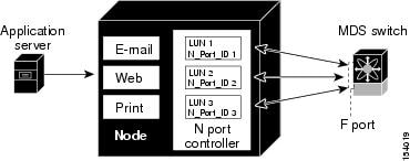
Information About N Port Identifier Virtualization
N port identifier virtualization (NPIV) provides a means to assign multiple FC IDs to a single N port. This feature allows multiple applications on the N port to use different identifiers and allows access control, zoning, and port security to be implemented at the application level. The following figure shows an example application using NPIV.
Enabling N Port Identifier Virtualization
Before You BeginProcedureYou must globally enable NPIV for all VSANs on the switch to allow the NPIV-enabled applications to use multiple N port identifiers.
Note
All of the N port identifiers are allocated in the same VSAN.
Command or Action Purpose
Step 1 configure terminal
Example:switch# configure terminal switch(config)#Enters configuration mode.
Step 2 feature npiv
Example:switch(config)# feature npivEnables NPIV for all VSANs on the switch.
Step 3 no feature npiv
Example:switch(config)# no feature npivDisables (default) NPIV on the switch.
Example Port Channel Configurations
This section shows examples on how to configure an F port channel in shared mode and how to bring up the link between F ports on the NPIV core switches and NP ports on the NPV switches. Before you configure the F port channel, ensure that F port trunking, F port channeling, and NPIV are enabled.
This example shows how to create the port channel:
switch(config)# interface port-channel 2switch(config-if)# switchport mode Fswitch(config-if)# switchport dedicatedswitch(config-if)# channel mode activeswitch(config-if)# exitThis example shows how to configure the port channel member interfaces on the core switch in dedicated mode:
switch(config)# interface fc1/4-6switch(config-if)# shutswitch(config-if)# switchport mode Fswitch(config-if)# switchport speed 4000switch(config-if)# switchport rate-mode dedicatedswitch(config-if)# switchport trunk mode onswitch(config-if)# channel-group 2switch(config-if)# no shutswitch(config-if)# exitThis example shows how to create the port channel in dedicated mode on the NPV switch:
switch(config)# interface san-port-channel 2switch(config-if)# switchport mode NPswitch(config-if)# no shutswitch(config-if)# exitThis example shows how to configure the port channel member interfaces on the NPV switch:
switch(config)# interface fc2/1-2switch(config-if)# shutswitch(config-if)# switchport mode NPswitch(config-if)# switchport trunk mode onswitch(config-if)# channel-group 2switch(config-if)# no shutswitch(config-if)# exitVerifying Fibre Channel Interfaces
Verifying SFP Transmitter Types
The SPF transmitter type can be displayed for a physical Fibre Channel interface (but not for a virtual Fibre Channel).
The small form-factor pluggable (SFP) hardware transmitters are identified by their acronyms when displayed in the show interface brief command. If the related SFP has a Cisco-assigned extended ID, then the show interface and show interface brief commands display the ID instead of the transmitter type. The show interface transceiver command and the show interface fc slot/port transceiver command display both values for Cisco supported SFPs.
Verifying Interface Information
The show interface command displays interface configurations. If no arguments are provided, this command displays the information for all the configured interfaces in the switch.
You can also specify arguments (a range of interfaces or multiple, specified interfaces) to display interface information. You can specify a range of interfaces by entering a command with the following example format: interface fc2/1 - 4 , fc3/2 - 3
The following example shows how to display all interfaces:
switch# show interface

fc3/1 is up
...
fc3/3 is up
...
Ethernet1/3 is up
...
mgmt0 is up
...
vethernet1/1 is up
...
vfc 1 is up
The following example shows how to display multiple specified interfaces:
switch# show interface fc3/1 , fc3/3
fc3/1 is up
...
fc3/3 is up
...
The following example shows how to display a specific interface:
switch# show interface vfc 1vfc 1 is up...The following example shows how to display interface descriptions:
switch# show interface description
-------------------------------------------------
Interface          Description
-------------------------------------------------
fc3/1              test intest
Ethernet1/1              --
vfc 1              --
...
The following example shows how to display all interfaces in brief:
switch# show interface briefThe following example shows how to display interface counters:
switch# show interface countersThe following example shows how to display transceiver information for a specific interface:
switch# show interface fc3/1 transceiver
Note
The show interface transceiver command is only valid if the SFP is present.
The show running-configuration command displays the entire running configuration with information for all interfaces. The interfaces have multiple entries in the configuration files to ensure that the interface configuration commands execute in the correct order when the switch reloads. If you display the running configuration for a specific interface, all the configuration commands for that interface are grouped together.
The following example shows the interface display when showing the running configuration for all interfaces:
switch# show running configuration
...
interface fc3/5
  switchport speed 2000
...
interface fc3/5
  switchport mode E
...
interface fc3/5
  channel-group 11 force
  no shutdown
The following example shows the interface display when showing the running configuration for a specific interface:
switch# show running configuration fc3/5
interface fc3/5
  switchport speed 2000
  switchport mode E
  channel-group 11 force
  no shutdown
Verifying BB_Credit Information
The following example shows how to display the BB_credit information for all Fibre Channel interfaces:
switch# show interface bbcredit...fc2/3 is trunkingTransmit B2B Credit is 255Receive B2B Credit is 12Receive B2B Credit performance buffers is 37512 receive B2B credit remaining255 transmit B2B credit remainingDefault Fibre Channel Interface Settings
The following table lists the default settings for native Fibre Channel interface parameters.
Table 5 Default Native Fibre Channel Interface Parameters Parameters
Default
Interface mode
Auto
Interface speed
Auto
Administrative state
Shutdown (unless changed during initial setup)
Trunk mode
On (unless changed during initial setup)
Trunk-allowed VSANs
1 to 4093
Interface VSAN
Default VSAN (1)
Beacon mode
Off (disabled)
EISL encapsulation
Disabled
Data field size
2112 bytes
The following table lists the default settings for virtual Fibre Channel interface parameters.
Table 6 Default Virtual Fibre Channel Interface Parameters Parameters
Default
Interface mode
F mode
Interface speed
n/a
Administrative state
Shutdown (unless changed during initial setup)
Trunk mode
On
Trunk-allowed VSANs
All VSANs
Interface VSAN
Default VSAN (1)
EISL encapsulation
n/a
Data field size
n/a