-
Cisco Nexus 5500 Series NX-OS SAN Switching Configuration Guide, Release 7.x
-
Preface
-
Overview
-
Configuring Fibre Channel Interfaces
-
Configuring Fibre Channel Domain Parameters
-
Configuring N Port Virtualization
-
Configuring FCoE NPV
-
Configuring VSAN Trunking
-
Configuring SAN Port Channels
-
Configuring and Managing VSANs
-
Configuring and Managing Zones
-
Distributing Device Alias Services
-
Configuring Fibre Channel Routing Services and Protocols
-
Managing FLOGI, Name Server, FDMI, and RSCN Databases
-
Discovering SCSI Targets
-
Configuring iSCSI TLV
-
Advanced Fibre Channel Features
-
Configuring FC-SP and DHCHAP
-
Configuring Port Security
-
Configuring Fabric Binding
-
Configuring Fabric Configuration Servers
-
Configuring Port Tracking
-
Index
-
 Feedback
Contents
- Configuring and Managing VSANs
- Configuring and Managing VSANs
- Information About VSANs
- VSAN Topologies
- VSAN Advantages
- VSANs Versus Zones
- Guidelines and Limitations for VSANs
- About VSAN Creation
- Creating VSANs Statically
- Port VSAN Membership
- Assigning Static Port VSAN Membership
- Displaying VSAN Static Membership
- Default VSANs
- Isolated VSANs
- Displaying Isolated VSAN Membership
- Operational State of a VSAN
- Static VSAN Deletion
- Deleting Static VSANs
- About Load Balancing
- Configuring Load Balancing
- Interop Mode
- Displaying the Static VSAN Configuration
- Default Settings for VSANs
Configuring and Managing VSANs
This chapter describes how to configure and manage VSANs.
This chapter includes the following sections:
Configuring and Managing VSANs
You can achieve higher security and greater stability in Fibre Channel fabrics by using virtual SANs (VSANs). VSANs provide isolation among devices that are physically connected to the same fabric. With VSANs you can create multiple logical SANs over a common physical infrastructure. Each VSAN can contain up to 239 switches and has an independent address space that allows identical Fibre Channel IDs (FC IDs) to be used simultaneously in different VSANs.
- Information About VSANs
- Guidelines and Limitations for VSANs
- Displaying the Static VSAN Configuration
- Default Settings for VSANs
Information About VSANs
A VSAN is a virtual storage area network (SAN). A SAN is a dedicated network that interconnects hosts and storage devices primarily to exchange SCSI traffic. In SANs you use the physical links to make these interconnections. A set of protocols run over the SAN to handle routing, naming, and zoning. You can design multiple SANs with different topologies.
You can achieve higher security and greater stability in Fibre Channel fabrics by using virtual SANs (VSANs). VSANs provide isolation among devices that are physically connected to the same fabric. With VSANs you can create multiple logical SANs over a common physical infrastructure. Each VSAN can contain up to 239 switches and has an independent address space that allows identical Fibre Channel IDs (FC IDs) to be used simultaneously in different VSANs.
VSAN Topologies
A VSAN has the following additional features:
- Multiple VSANs can share the same physical topology.
- The same Fibre Channel IDs (FC IDs) can be assigned to a host in another VSAN, which increases VSAN scalability.
- Every instance of a VSAN runs all required protocols such as FSPF, domain manager, and zoning.
- Fabric-related configurations in one VSAN do not affect the associated traffic in another VSAN.
- Events causing traffic disruptions in one VSAN are contained within that VSAN and are not propagated to other VSANs.
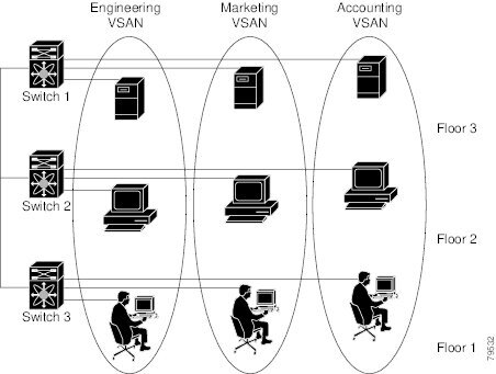
The following figure shows a fabric with three switches, one on each floor. The geographic location of the switches and the attached devices is independent of their segmentation into logical VSANs. No communication between VSANs is possible. Within each VSAN, all members can talk to one another.
The application servers or storage arrays can be connected to the switch using Fibre Channel or virtual Fibre Channel interfaces. A VSAN can include a mixture of Fibre Channel and virtual Fibre Channel interfaces.
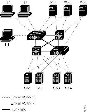
The following figure shows a physical Fibre Channel switching infrastructure with two defined VSANs: VSAN 2 (dashed) and VSAN 7 (solid). VSAN 2 includes hosts H1 and H2, application servers AS2 and AS3, and storage arrays SA1 and SA4. VSAN 7 connects H3, AS1, SA2, and SA3.
The four switches in this network are interconnected by VSAN trunk links that carry both VSAN 2 and VSAN 7 traffic. You can configure a different inter-switch topology for each VSAN. In the preceding figure, the inter-switch topology is identical for VSAN 2 and VSAN 7.
Without VSANs, a network administrator would need separate switches and links for separate SANs. By enabling VSANs, the same switches and links might be shared by multiple VSANs. VSANs allow SANs to be built on port granularity instead of switch granularity. The preceding figure illustrates that a VSAN is a group of hosts or storage devices that communicate with each other using a virtual topology defined on the physical SAN.
The criteria for creating such groups differ based on the VSAN topology:
VSAN Advantages
VSANs offer the following advantages:
- Traffic isolation—Traffic is contained within VSAN boundaries and devices reside only in one VSAN ensuring absolute separation between user groups, if desired.
- Scalability—VSANs are overlaid on top of a single physical fabric. The ability to create several logical VSAN layers increases the scalability of the SAN.
- Per VSAN fabric services—Replication of fabric services on a per VSAN basis provides increased scalability and availability.
- Redundancy—Several VSANs created on the same physical SAN ensure redundancy. If one VSAN fails, redundant protection (to another VSAN in the same physical SAN) is configured using a backup path between the host and the device.
- Ease of configuration—Users can be added, moved, or changed between VSANs without changing the physical structure of a SAN. Moving a device from one VSAN to another only requires configuration at the port level, not at a physical level.
Up to 256 VSANs can be configured in a switch. Of these, one is a default VSAN (VSAN 1), and another is an isolated VSAN (VSAN 4094). User-specified VSAN IDs range from 2 to 4093.
VSANs Versus Zones
Zones are always contained within a VSAN. You can define multiple zones in a VSAN.
Because two VSANs are equivalent to two unconnected SANs, zone A on VSAN 1 is different and separate from zone A in VSAN 2. The following table lists the differences between VSANs and zones.
Table 1 VSAN and Zone Comparison VSAN Characteristic
Zone Characteristic
VSANs equal SANs with routing, naming, and zoning protocols.
Routing, naming, and zoning protocols are not available on a per-zone basis.
VSANs limit unicast, multicast, and broadcast traffic.
Zones limit unicast traffic.
Membership is typically defined using the VSAN ID to F ports.
Membership is typically defined by the pWWN.
An HBA or a storage device can belong only to a single VSAN (the VSAN associated with the F port).
An HBA or storage device can belong to multiple zones.
VSANs enforce membership at each E port, source port, and destination port.
Zones enforce membership only at the source and destination ports.
VSANs are defined for larger environments (storage service providers).
Zones are defined for a set of initiators and targets not visible outside the zone.
VSANs encompass the entire fabric.
Zones are configured at the fabric edge.
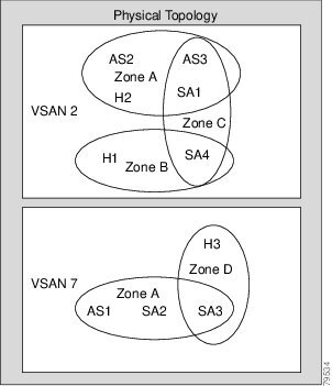
The following figure shows the possible relationships between VSANs and zones. In VSAN 2, three zones are defined: zone A, zone B, and zone C. Zone C overlaps both zone A and zone B as permitted by Fibre Channel standards. In VSAN 7, two zones are defined: zone A and zone D. No zone crosses the VSAN boundary. Zone A defined in VSAN 2 is different and separate from zone A defined in VSAN 7.
Guidelines and Limitations for VSANs
VSANs have the following configuration guidelines and limitations:
- VSAN ID—The VSAN ID identifies the VSAN as the default VSAN (VSAN 1), user-defined VSANs (VSAN 2 to 4093), and the isolated VSAN (VSAN 4094).
- State—The administrative state of a VSAN can be configured to an active (default) or suspended state. Once VSANs are created, they may exist in various conditions or states.
- The active state of a VSAN indicates that the VSAN is configured and enabled. By enabling a VSAN, you activate the services for that VSAN.
- The suspended state of a VSAN indicates that the VSAN is configured but not enabled. If a port is configured in this VSAN, it is disabled. Use this state to deactivate a VSAN without losing the VSAN’s configuration. All ports in a suspended VSAN are disabled. By suspending a VSAN, you can preconfigure all the VSAN parameters for the whole fabric and activate the VSAN immediately.
- VSAN name—This text string identifies the VSAN for management purposes. The name can be from 1 to 32 characters long and it must be unique across all VSANs. By default, the VSAN name is a concatenation of VSAN and a four-digit string representing the VSAN ID. For example, the default name for VSAN 3 is VSAN0003.
Note
A VSAN name must be unique.
- Load-balancing attributes—These attributes indicate the use of the source-destination ID (src-dst-id) or the originator exchange OX ID (src-dst-ox-id, the default) for load-balancing path selection.
- A VSAN is in the operational state if the VSAN is active and at least one port is up. This state indicates that traffic can pass through this VSAN. This state cannot be configured.
- About VSAN Creation
- Creating VSANs Statically
- Port VSAN Membership
- Assigning Static Port VSAN Membership
- Displaying VSAN Static Membership
- Default VSANs
- Isolated VSANs
- Displaying Isolated VSAN Membership
- Operational State of a VSAN
- Static VSAN Deletion
- Deleting Static VSANs
- About Load Balancing
- Configuring Load Balancing
- Interop Mode
Creating VSANs Statically
ProcedurePort VSAN Membership
Port VSAN membership on the switch is assigned on a port-by-port basis. By default each port belongs to the default VSAN. You can assign VSAN membership to ports using one of two methods:
- Statically—Assigning VSANs to ports.
- Dynamically—Assigning VSANs based on the device WWN. This method is referred to as dynamic port VSAN membership (DPVM).Cisco Nexus devices do not support DPVM.
VSAN trunking ports have an associated list of VSANs that are part of an allowed list.
Related Tasks
Related Information
Assigning Static Port VSAN Membership
ProcedureDisplaying VSAN Static Membership
To display the VSAN static membership information, use the show vsan membership command.
The following example displays membership information for the specified VSAN:
switch # show vsan 1 membershipvsan 1 interfaces:fc2/1 fc2/2 fc2/3 fc2/4san-port-channel 3 vfc1/1
Note
Interface information is not displayed if interfaces are not configured on this VSAN.
The following example displays membership information for all VSANs:
switch # show vsan membershipvsan 1 interfaces:fc2/1 fc2/2 fc2/3 fc2/4san-port-channel 3 vfc3/1vsan 2 interfaces:fc2/3 vfc4/1vsan 7 interfaces:vsan 100 interfaces:vsan 4094(isolated vsan) interfaces:The following example displays static membership information for the specified interface:
switch # show vsan membership interface fc2/1
fc2/1
        vsan:1
        allowed list:1-4093
Default VSANs
The factory settings for Cisco SAN switches have only the default VSAN 1 enabled. We recommend that you do not use VSAN 1 as your production environment VSAN. If no VSANs are configured, all devices in the fabric are considered part of the default VSAN. By default, all ports are assigned to the default VSAN.
Note
VSAN 1 cannot be deleted, but it can be suspended.
Up to 256 VSANs can be configured in a switch. Of these, one is a default VSAN (VSAN 1), and another is an isolated VSAN (VSAN 4094). User-specified VSAN IDs range from 2 to 4093.
Isolated VSANs
VSAN 4094 is an isolated VSAN. When a VSAN is deleted, all nontrunking ports are transferred to the isolated VSAN to avoid an implicit transfer of ports to the default VSAN or to another configured VSAN. This action ensures that all ports in the deleted VSAN become isolated (disabled).
Note
When you configure a port in VSAN 4094 or move a port to VSAN 4094, that port is immediately isolated.
Caution
Do not use an isolated VSAN to configure ports.
Note
Up to 256 VSANs can be configured in a switch. Of these, one is a default VSAN (VSAN 1), and another is an isolated VSAN (VSAN 4094). User-specified VSAN IDs range from 2 to 4093.
Static VSAN Deletion
When an active VSAN is deleted, all of its attributes are removed from the running configuration. VSAN-related information is maintained by the system software as follows:
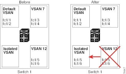
- VSAN attributes and port membership details are maintained by the VSAN manager. This feature is affected when you delete a VSAN from the configuration. When a VSAN is deleted, all the ports in that VSAN are made inactive and the ports are moved to the isolated VSAN. If the same VSAN is recreated, the ports do not automatically get assigned to that VSAN. You must explicitly reconfigure the port VSAN membership (see the figure below).
- VSAN-based runtime (name server), zoning, and configuration (static routes) information is removed when the VSAN is deleted.
- Configured VSAN interface information is removed when the VSAN is deleted.
Note
The allowed VSAN list is not affected when a VSAN is deleted.
Any commands for a nonconfigured VSAN are rejected. For example, if VSAN 10 is not configured in the system, a command request to move a port to VSAN 10 is rejected.
Related Information
Deleting Static VSANs
Procedure
Command or Action Purpose
Step 1 configure terminal
Example:switch# configure terminal switch(config)#Enters global configuration mode.
Step 2 vsan database
Example:switch(config)# vsan database switch(config-vsan-db)#Configures the VSAN database.
Step 3 vsan vsan-id
Example:switch(config-vsan-db)# vsan 2Places you in VSAN configuration mode.
Step 4 switch(config-vsan-db)# no vsanvsan-id
Example:switch(config-vsan-db)# no vsan 5Deletes VSAN 5 from the database and switch.
Step 5 switch(config-vsan-db)# end
Example:switch(config-vsan-db)# endPlaces you in EXEC mode.
Configuring Load Balancing
ProcedureYou can configure load balancing on an existing VSAN.
Load-balancing attributes indicate the use of the source-destination ID (src-dst-id) or the originator exchange OX ID (src-dst-ox-id, the default) for load-balancing path selection.
Command or Action Purpose
Step 1 configure terminal
Example:switch# configure terminal switch(config)#Enters global configuration mode.
Step 2 vsan database
Example:switch(config)# vsan database switch(config-vsan-db)#Enters VSAN database configuration submode
Step 3 vsan vsan-id
Example:switch(config-vsan-db)# vsan 15Specifies an existing VSAN.
Step 4 vsan vsan-id loadbalancing src-dst-id
Example:switch(config-vsan-db)# vsan 15 loadbalancing src-dst-idEnables the load-balancing guarantee for the selected VSAN and directs the switch to use the source and destination ID for its path selection process.
Step 5 no vsan vsan-id loadbalancing src-dst-id
Example:switch(config-vsan-db)# no vsan 15 loadbalancing src-dst-idNegates the command entered in the previous step and reverts to the default values of the load-balancing parameters.
Step 6 vsan vsan-id loadbalancing src-dst-ox-id
Example:switch(config-vsan-db)# vsan 15 loadbalancing src-dst-ox-idChanges the path selection setting to use the source ID, the destination ID, and the OX ID (default).
Step 7 vsan vsan-id suspend
Example:switch(config-vsan-db)# vsan 23 suspendSuspends the selected VSAN.
Step 8 no vsan vsan-id suspend
Example:switch(config-vsan-db)# no vsan 23 suspendNegates the suspend command entered in the previous step.
Step 9 end
Example:switch(config-vsan-db)# endReturns you to EXEC mode.
Displaying the Static VSAN Configuration
The following example shows how to display information about a specific VSAN:
switch# show vsan 100The following example shows how to display VSAN usage:
switch# show vsan usage4 vsan configuredconfigured vsans:1-4vsans available for configuration:5-4093The following example shows how to display all VSANs:
switch# show vsan