Cisco MDS 9000 Family Troubleshooting Guide, Release 3.x
Troubleshooting VSANs, Domains, and FSPF

Table Of Contents

Troubleshooting VSANs, Domains, and FSPF

Overview

Initial Troubleshooting Checklist

Common Troubleshooting Tools in Fabric Manager

Common Troubleshooting Commands in the CLI

VSAN Issues

Host Cannot Communicate with Storage

Verifying VSAN Membership Using Fabric Manager

Verifying VSAN Membership Using the CLI

E Port Is Isolated in a VSAN

Resolving an Isolated E Port Using Fabric Manager

Resolving an Isolated E Port Using the CLI

Resolving an Isolated ISL Using Fabric Manager

Resolving an Isolated ISL Using the CLI

Resolving Fabric Timer Issues Using Fabric Manager

Resolving Fabric Timer Issues Using the CLI

Troubleshooting Interop Mode Issues

Dynamic Port VSAN Membership Issues

Troubleshooting DPVM Using Fabric Manager

Troubleshooting DPVM Using the CLI

DPVM Configuration Not Available

DPVM Database Not Distributed

DPVM Autolearn Not Working

No Autolearn Entries in Active Database

VSAN Membership not Added to Database

DPVM Config Database Not Activating

Cannot Copy Active to Config DPVM Database

Port Suspended or Disabled After DPVM Activation

DPVM Merge Failed

DPVM Process Terminates

Disabling DPVM

Domain Issues

Domain ID Conflict Troubleshooting

Switch Cannot See Other Switches in a VSAN

FC Domain ID Overlap

Assigning a New Domain ID Using Fabric Manager

Assigning a New Domain ID Using the CLI

Using Fabric Reconfiguration for Domain ID Assignments

CFS Distribution of Domain ID List Fails

Allowed Domain ID List Incorrect After a VSAN Merge

Changes to fcdomain Do Not Take Effect

FSPF Issues

Troubleshooting FSPF

Troubleshooting FSPF Using Device Manager

Troubleshooting FSPF Using the CLI

Loss of Two-Way Communication

Resolving a Wrong Hello Interval on an ISL Using Device Manager

Resolving a Wrong Hello Interval on an ISL Using the CLI

Resolving a Mismatched Retransmit Interval on an ISL Using Device Manager

Resolving a Mismatched Retransmit Interval on an ISL Using the CLI

Resolving a Mismatch in Dead Intervals on an ISL Using Fabric Manager

Resolving a Mismatch in Dead Intervals on an ISL Using the CLI

Resolving a Region Mismatch Using Fabric Manager

Resolving a Region Mismatch Using the CLI


Troubleshooting VSANs, Domains, and FSPF


This chapter describes how to identify and resolve problems that might occur when implementing VSANs, domains, and FSPF. This chapter includes the following sections:

Overview

Initial Troubleshooting Checklist

VSAN Issues

Dynamic Port VSAN Membership Issues

Domain Issues

FSPF Issues

Overview

Virtual SANs (VSANs) provide a method of isolating devices that are physically connected to the same storage network, but are logically considered to be part of different SAN fabrics that do not need to be aware of one another. Each VSAN can contain up to 239 switches and has an independent address space that allows identical Fibre Channel IDs (FC IDs) to be used simultaneously in different VSANs.

VSANs provide the following capabilities:

Isolate devices physically connected to the same fabric.

Reduce the size of a Fibre Channel distributed database.

Enable more scalable and secure fabrics.

Initial Troubleshooting Checklist

Most VSAN problems can be avoided by following the best practices for VSAN implementation. However, if needed, you can use the Fabric Analysis tool in Fabric Manager to verify different categories of problems such as VSANs, zoning, FCdomain, admin issues, or switch-specific or fabric-specific issues.

Fabric Manager provides the configuration consistency check tool. Refer to the Cisco MDS 9000 Fabric Manager Configuration Guide for more information about this tool.


Note When suspending or deleting VSANs, make sure that you suspend and unsuspend one VSAN at a time, and that you wait a minimum of 60 seconds after you issue the vsan suspend command before you issue any other config command. Failure to do so may result in some Fibre Channel interfaces or member ports in a PortChannel becoming suspended or error-disabled.


Troubleshooting a SAN problem involves gathering information about the configuration and connectivity of individual devices as well as the status of the entire SAN fabric. In the case of VSANs, begin your troubleshooting activity as follows:

Checklist 
Check off

Verify the FSPF parameters for switches in the VSAN.

Verify the domain parameters for switches in the VSAN.

Verify the physical connectivity for any problem ports or VSANs.

Verify that you have both devices in the name server.

Verify that you have both end devices in the same VSAN.

Verify that you have both end devices in the same zone.

Verify that the zone is part of the active zone set.


Common Troubleshooting Tools in Fabric Manager

Use the following Fabric Manager procedures to verify the VSAN, FC domain, FSPF, and zone s:

Choose Fabricxx > VSANxx to view the VSAN configuration in the Information pane.

Choose Fabricxx > VSANxx and select the Host or Storage tab in the Information pane to view the VSAN members.

Choose Fabricxx > VSANxx > Domain Manager to view the FC domain configuration in the Information pane.

Choose Fabricxx > VSANxx > FSPF to view the FSPF configuration in the Information pane.

Choose Fabricxx > VSANxx > zoneset-name to view the zone configuration for this VSAN. Zone configuration problems may appear to be a VSAN problem.

Common Troubleshooting Commands in the CLI

Use the following CLI commands to display VSAN, FC domain, and FSPF information:

show vsan

show vsan vsan-id

show vsan membership

show interface fc slot/port trunk vsan-id

show vsan-id membership

show vsan membership interface fc slot/port

show fcdomain

show fspf

show fspf internal route vsan vsan-id

show fcns database vsan vsan-id

Use the following zone CLI commands to validate your configuration:

show zoneset name zoneset-name vsan vsan-id

show zoneset active vsan vsan-id


Note An asterix (*) near the device listed by the show zoneset active command indicates that the device is logged into the name server.


show zone vsan vsan-id

show zone status show vsan vsan-range


Note For more information on zoning issues, see Chapter 14, "Troubleshooting Zones and Zone Sets."


VSAN Issues

This section includes the following topics:

Host Cannot Communicate with Storage

E Port Is Isolated in a VSAN

Troubleshooting Interop Mode Issues

Host Cannot Communicate with Storage

Communication problems between a host and storage devices can be caused by port, VSAN, or zone issues.

Symptom    Host cannot communicate with storage.

Table 11-1 Host Cannot Communicate with Storage

Symptom
Possible Cause
Solution

Host cannot communicate with storage.

Host and storage are not in the same VSAN.

Verify the VSAN membership. See the "Verifying VSAN Membership Using Fabric Manager" section or the "Verifying VSAN Membership Using the CLI" section.

xE port connecting to the remote switch is isolated.

See the "E Port Is Isolated in a VSAN" section.

Host and storage are not in the same zone.

See the "Zone and Zone Set Issues" section on page 14-4.


Verifying VSAN Membership Using Fabric Manager

To verify VSAN membership for host and storage devices using Fabric Manager, follow these steps:


Step 1 Choose Fabricxx > VSANxx and select the Host or Storage tab in the Information pane. Verify that both devices are in the same VSAN.

Step 2 If the host and storage are in different VSANs, verify which port is not in the correct VSAN and then follow these steps to change the port VSAN:

a. Highlight the host or storage in the Information pane. You see the link to that end device highlighted in blue in the map pane.

b. Right-click on the highlighted link and select Interface Attributes from the pop-up menu.

c. Set the PortVSAN field to the VSAN that holds the other end device and click Apply Changes.

Step 3 Right-click any ISL between the switches and select Interface Attributes. Select the Trunk Config tab and verify that the allowed VSAN list includes the VSAN found in Step 1.

Step 4 If the trunk is not configured for the VSAN, set the Allowed VSANs field to include the VSAN that the host and storage devices are on and click Apply Changes.


Verifying VSAN Membership Using the CLI

To verify VSAN membership for host and storage devices using the CLI, follow these steps:


Step 1 Use the show vsan membership command to see all the ports connected to your host and storage, and verify that both devices are in the same VSAN. Use this command on the switches that connect to your host or storage devices.

switch# show vsan membership 
vsan 1 interfaces:
        fc2/7   fc2/8   fc2/9   fc2/10  fc2/11  fc2/12  fc2/13  fc2/14
        fc2/15  fc2/16  fc7/1   fc7/2   fc7/3   fc7/4   fc7/5   fc7/6
        fc7/7   fc7/8   fc7/9   fc7/10  fc7/11  fc7/12  fc7/13  fc7/14
        fc7/15  fc7/16  fc7/17  fc7/18  fc7/19  fc7/20  fc7/21  fc7/22
        fc7/25  fc7/26  fc7/27  fc7/28  fc7/29  fc7/30  fc7/31  fc7/32

vsan 2 interfaces:
        fc2/6   fc7/23  fc7/24

vsan 3 interfaces:
        fc2/1   fc2/2   fc2/5

vsan 4 interfaces:
        fc2/3   fc2/4

Step 2 If the host and storage are in different VSANs, use the vsan database vsan vsan-id interface command to move the interface connected to the host and storage devices into the same VSAN.

Step 3 Use the show interface command to verify that the trunks connecting the end switches are configured to transport the VSAN found in Step 1.

 switch# show interface fc2/14
 fc2/14 is trunking
    Hardware is Fibre Channel, WWN is 20:4e:00:05:30:00:63:9e
    Port mode is TE
    Speed is 2 Gbps
    vsan is 2
    Beacon is turned off
    Trunk vsans (allowed active) (1-3,5)
    Trunk vsans (operational)    (1-3,5)
    Trunk vsans (up)             (2-3,5)
    Trunk vsans (isolated)       (1)
    Trunk vsans (initializing)   ()
      475 frames input, 8982 bytes, 0 discards
      0 runts, 0 jabber, 0 too long, 0 too short
      0 input errors, 0 CRC, 3 invalid transmission words
      0 address id, 0 delimiter
      0 EOF abort, 0 fragmented, 0 unknown class
      514 frames output, 7509 bytes, 16777216 discards
      Received 30 OLS, 21 LRR, 18 NOS, 53 loop inits
      Transmitted 68 OLS, 25 LRR, 28 NOS, 32 loop inits

Step 4 If the trunk is not configured for the VSAN, use the interface command and then the switchport trunk allowed vsan command in interface mode to add the VSAN to the allowed VSAN list for the interface that connects the host and storage devices.


E Port Is Isolated in a VSAN

Symptom    E port is isolated in a VSAN.

Table 11-2 xE Port Is Isolated in a VSAN 

Symptom
Possible Cause
Solution

E port is isolated in a VSAN.

E port connecting to the remote switch is isolated.

Verify the VSAN. See the "Resolving an Isolated E Port Using Fabric Manager" section or the "Resolving an Isolated E Port Using Fabric Manager" section.

TE port connecting to the remote switch is isolated.

See the "Resolving an Isolated ISL Using Fabric Manager" section or the "Resolving an Isolated ISL Using the CLI" section

Fabric timers misconfigured.

Use caution when changing fabric timers. See the "Resolving Fabric Timer Issues Using Fabric Manager" section or the "Resolving Fabric Timer Issues Using the CLI" section.

Port parameters misconfigured.

See the "Common Problems with Port Interfaces" section on page 8-13.

Zoning mismatch.

See Chapter 14, "Troubleshooting Zones and Zone Sets."


Resolving an Isolated E Port Using Fabric Manager

To resolve VSAN isolation on an E port using Fabric Manager, follow these steps:


Step 1 Choose Switches > Interfaces > FC Physical and check the FailureCause column on the E port to verify that you have a VSAN mismatch.

Step 2 Choose Switches > Interfaces > FC Physical and use the PortVSAN field to correct a VSAN mismatch.


Resolving an Isolated E Port Using the CLI

To resolve VSAN isolation on an E port using the CLI, follow these steps:


Step 1 Use the show interface command to verify that the port is isolated because of a VSAN mismatch.

switch# show interface fc2/4
fc2/4 is down fc2/4 is down (isolation due to port vsan mismatch) 

    Hardware is Fibre Channel, WWN is 20:44:00:05:30:00:63:5e
    vsan is 4
    Beacon is turned off
      30 frames input, 682 bytes, 0 discards
      0 runts, 0 jabber, 0 too long, 0 too short
      0 input errors, 0 CRC, 0 invalid transmission words
      0 address id, 0 delimiter
      0 EOF abort, 0 fragmented, 0 unknown class
      30 frames output, 583 bytes, 0 discards
      Received 2 OLS, 2 LRR, 2 NOS, 5 loop inits
      Transmitted 5 OLS, 3 LRR, 2 NOS, 4 loop inits

Step 2 Use the show vsan membership command to verify that the ports are in separate VSANs.

switch# show vsan membership
vsan 3 interfaces:
        fc2/1   fc2/2   fc2/3   fc2/4   fc2/6   fc2/7   fc2/8   fc2/9
        fc2/10  fc2/11  fc2/12  fc2/14  fc2/15  fc2/16  fc7/1   fc7/2
        fc7/3   fc7/4   fc7/5   fc7/6   fc7/7   fc7/8   fc7/9   fc7/10
        fc7/11  fc7/12  fc7/13  fc7/14  fc7/15  fc7/16  fc7/17  fc7/18
        fc7/19  fc7/20  fc7/21  fc7/22  fc7/23  fc7/24  fc7/25  fc7/26
        fc7/27  fc7/28  fc7/29  fc7/30  fc7/31  fc7/32

vsan 4 interfaces:
        fc2/5   fc2/13

vsan 4094(isolated_vsan) interfaces:

This sample output shows that all the interfaces on the switch belong to VSAN 3, with the exception of interface fc2/5 and fc2/13, which are part of VSAN 4.

Step 3 Use the vsan database vsan vsan-id interface command to move the ports into the same VSAN.


Resolving an Isolated ISL Using Fabric Manager

Trunking E ports (TE ports) are similar to E ports except that they carry traffic for multiple VSANs. E ports carry traffic for a single VSAN. Because TE ports carry traffic for multiple VSANs, ISL isolation can affect one or more VSANs. For this reason, on a TE port you must troubleshoot for ISL isolation on each VSAN.

To resolve VSAN isolation on a TE port using Fabric Manager, follow these steps:


Step 1 Choose Switches > Interfaces > FC Physical and check the FailureCause column on the TE port to verify that you have a trunk problem.

Step 2 Choose Switches > Interfaces > FC Physical and select the Trunk Failures tab to determine the reason for the trunk problem.

Step 3 Correct the problem listed in the FailureCause column. See the "DPVM Config Database Not Activating" section for domain misconfiguration problems. Choose Switches > Interfaces > FC Physical and use the PortVSAN field to correct the VSAN misconfiguration problems.

Step 4 Repeat this procedure for all isolated VSANs on this TE port.


Resolving an Isolated ISL Using the CLI

Trunking E ports (TE ports) are similar to E ports except that they carry traffic for multiple VSANs. E ports carry traffic for a single VSAN. Because TE ports carry traffic for multiple VSANs, ISL isolation can affect one or more VSANs. For this reason, on a TE port you must troubleshoot for ISL isolation on each VSAN.

To resolve VSAN isolation on a TE port using the CLI, follow these steps:


Step 1 Use the show interface command on the TE port to verify that you have an isolated VSAN.

switch# show interface fc2/14
fc2/14 is trunking
    Hardware is Fibre Channel, WWN is 20:4e:00:05:30:00:63:9e
    Port mode is TE
    Speed is 2 Gbps
    vsan is 2
    Beacon is turned off
    Trunk vsans (allowed active) (1-3,5)
    Trunk vsans (operational)    (1-3,5)
    Trunk vsans (up)             (2-3,5)
    Trunk vsans (isolated)       (1)
    Trunk vsans (initializing)   ()
      475 frames input, 8982 bytes, 0 discards
      0 runts, 0 jabber, 0 too long, 0 too short
      0 input errors, 0 CRC, 3 invalid transmission words
      0 address id, 0 delimiter
      0 EOF abort, 0 fragmented, 0 unknown class
      514 frames output, 7509 bytes, 16777216 discards
      Received 30 OLS, 21 LRR, 18 NOS, 53 loop inits

The example shows the output of the show interface command with one or more isolated VSANs. Here, the TE port has one VSAN isolated.

Step 2 Use the show interface fc slot/port trunk vsan vsan-id command to verify the reason for VSAN isolation.

switch# show interface fc2/14 trunk vsan 1
fc2/15 is trunking
    Vsan 1 is down (Isolation due to zone merge failure)

This output shows that VSAN 1 is isolated because of a zone merge error.

Step 3 Use the show port internal info interface fc slot/port command to determine the root cause of the VSAN isolation.


Note To issue commands with the internal keyword, you must have an account that is a member of the network-admin group.


switch# show port internal info interface fc2/14

fc2/14 - if_index: 0x0109C000, phy_port_index: 0x3c
  Admin Config - state(up), mode(TE), speed(auto), trunk(on)
    beacon(off), snmp trap(on), tem(false)
    rx bb_credit(default), rx bb_credit multiplier(default)
    rxbufsize(2112), encap(default), user_cfg_flag(0x3)
    description()
    Hw Capabilities: 0xb
    trunk vsans (up) (7)
    .
    .
    .
    trunk vsans (isolated) (1,8)
  TE port per vsan information
  fc2/29, Vsan 1 - state(down), state reason(Isolation due to domain other side eport 
isolated), fcid(0x000000)
    port init flag(0x10000), current state [TE_FSM_ST_ISOLATED_DM_ZS]
  fc2/29, Vsan 7 - state(up), state reason(None), fcid(0x690202)
    port init flag(0x38000), current state [TE_FSM_ST_E_PORT_UP]
  fc2/29, Vsan 8 - state(down), state reason(Isolation due to vsan not configured on 
peer), fcid(0x000000)
    port init flag(0x0), current state [TE_FSM_ST_ISOLATED_VSAN_MISMATCH]

The last few lines of the command output provide a description of the reason for VSAN isolation for every isolated VSAN.

In this example, VSAN 7 is up, while two VSANs are isolated. VSAN 1 is isolated because of domain ID misconfiguration, and VSAN 8 is isolated because of VSAN misconfiguration.

Step 4 Correct the root cause. See the "DPVM Config Database Not Activating" section for domain misconfiguration problems. Use the vsan vsan-id interface command to correct the VSAN misconfiguration problems.

Step 5 Repeat this procedure for all isolated VSANs on this TE port.


Resolving Fabric Timer Issues Using Fabric Manager

Use caution when changing fabric timers.

To resolve fabric timer issues between VSANs using Fabric Manager, follow these steps:


Step 1 Choose Fabricxx > VSANxx > VSAN Attributes to verify that the fabric timers are inconsistent across the VSANs.

Step 2 Choose Switches > FC Services > Timers and Policies. You see the fabric timers in the Information pane.

Step 3 Click Change Timeout Values and set the timers and click Apply.


Resolving Fabric Timer Issues Using the CLI

Use caution when changing fabric timers.

To resolve fabric timer issues between VSANs using the CLI, follow these steps:


Step 1 Use the show fctimer command to verify that the fabric timers are inconsistent across the VSANs.

Step 2 Use the fctimer distribute command to enable CFS distribution for the fabric timers. Repeat this on all switches in this VSAN.

Step 3 Use the fctimer command to set each timer.

Step 4 Use the fctimer commit command to save these changes and distribute them to all switches in the VSAN.


Troubleshooting Interop Mode Issues

To troubleshoot interop modes, refer to the switch to switch interop guide at the following website:

http://www.cisco.com/univercd/cc/td/doc/product/sn5000/mds9000/mdsint/intgd.pdf

Dynamic Port VSAN Membership Issues

You can dynamically assign VSAN membership to ports is achieved by assigning VSANs based on the device WWN. Dynamic port VSAN membership (DPVM) offers flexibility and eliminates the need to reconfigure the VSAN to maintain fabric topology when a host or storage device connection is moved between two switches or between ports on the same switch. It retains the configured VSAN regardless of where a device is connected or moved.

Verify the following requirements when using DPVM:

The interface through which the dynamic device connects to the Cisco MDS switch must be configured as an F port. FL ports do not support DPVM and no entries will be learned through an FL port.

The static port VSAN of the F port should be valid (not isolated, not suspended, and in existence).

The dynamic VSAN configured for the device in the DPVM database should be valid (not isolated, not suspended, and in existence).


Note The DPVM feature overrides any existing static port VSAN membership configuration. If the VSAN corresponding to the dynamic port is deleted or suspended, the port is shut down.


Note If you copy the DPVM database and fabric distribution is enabled, you must commit the changes.


To begin configuring DPVM, you must explicitly enable DPVM on the required switches in the fabric. By default, this feature is disabled in all switches in the Cisco MDS 9000 Family.

For more information on enabling DPVM, refer to one of the following guides:

Cisco MDS 9000 Family Fabric Manager Configuration Guide

Cisco MDS 9000 Family CLI Configuration Guide

This section contains the following topics:

Troubleshooting DPVM Using Fabric Manager

Troubleshooting DPVM Using the CLI

DPVM Configuration Not Available

DPVM Database Not Distributed

DPVM Autolearn Not Working

No Autolearn Entries in Active Database

VSAN Membership not Added to Database

DPVM Config Database Not Activating

Cannot Copy Active to Config DPVM Database

Port Suspended or Disabled After DPVM Activation

DPVM Merge Failed

DPVM Process Terminates

Troubleshooting DPVM Using Fabric Manager

To troubleshoot DPVM using Fabric Manager, follow these steps:


Step 1 Choose Fabricxx > All VSANs > DPVM and select the CFS tab.

Step 2 Verify that the Oper and Global columns are enabled. If not, set the Admin drop-down menu to enable and the Global drop-down menu to enable. Then click Apply Changes.

Step 3 Select the Actions tab. Uncheck AutoLearn Enable if it is checked and click Apply Changes.

Step 4 Select the Active Database tab.

Step 5 Select Pending from the Compare To drop-down menu. You see a dialog box listing any differences between the active DPVM database and the pending database.

Step 6 Select the CFS tab and set Config Action to commit if there are any pending changes that you want to save. Click Apply Changes.

Step 7 Select the Actions tab and select activate from the Actions drop-down menu to activate the database. Click Apply Changes.


Troubleshooting DPVM Using the CLI

To troubleshoot DPVM using the CLI, follow these steps:


Step 1 Use the show dpvm command in EXEC mode to verify that CFS distribution is enabled for DPVM.
Optionally, use the dpvm distribute command in config mode to enable CFS distribution if required.

Step 2 Use the show dpvm status command in EXEC mode to verify that autolearning is disabled.
Optionally, use the no dpvm auto-learn command in config mode if you need to disable autolearning before activating the database.

Step 3 Use the show dpvm pending-diff command in EXEC mode to compare the active and pending databases.
Optionally use the dpvm commit command in config mode to commit any pending entries to the config database.

Step 4 Use the dpvm activate command in config mode to activate the database.


DPVM Configuration Not Available

Symptom    DPVM configuration is not available on Fabric Manager or CLI.

Table 11-3 DPVM Configuration Not Available

Symptom
Possible Cause
Solution

DPVM configuration is not available on Fabric Manager or CLI.

DPVM has not been enabled.

DPVM must be enabled before it can be configured. Choose Fabricxx > All VSANs > DPVM and check the Status field in Fabric Manager or use the show dpvm status CLI command to verify that DPVM is not enabled. Set the Status field to enable in Fabric Manager and then click Apply Changes or use the dpvm enable CLI command to enable DPVM.


DPVM Database Not Distributed

Symptom    DPVM databases are not distributed.

Table 11-4 DPVM Database Not Distributed

Symptom
Possible Cause
Solution

DPVM databases are not distributed.

DPVM distribution has not been enabled on the local switch.

Choose Fabricxx > All VSANs > DPVM and select the CFS tab. Check the Global field in Fabric Manager or use the show dpvm status CLI command to verify that DPVM distribution is not enabled. Set the Global field to enable in Fabric Manager and then click Apply Changes or use the dpvm distribute CLI command to enable DPVM.

DPVM distribution has not been enabled on one or more remote switches.


DPVM Autolearn Not Working

The DPVM autolearn feature allows you to automatically populate the DPVM configuration database with all devices currently in the fabric. This feature is best used when you first turn on DPVM in a stable fabric. Once the devices are learned, you disable autolearning to populate the configuration database with these autolearned entries.

When you add a new device, it is a best practice to manually add that device to the DPVM configuration database. If you turn on autolearning for a new device, you may add other devices that you did not intend to add.

Symptom    DPVM autolearn does not work or is not getting enabled.

Table 11-5 DPVM Autolearn Not Working

Symptom
Possible Cause
Solution

DPVM autolearn does not work or is not getting enabled.

DPVM active database may be absent.

Choose Fabricxx > All VSANs > DPVM and select the Active Database tab in Fabric Manager or use the show dpvm database CLI command to verify that DPVM is not enabled. Select the Actions tab and set the Action field to activate in Fabric Manager and then click Apply Changes or use the dpvm activate and dpvm commit CLI commands to create the DPVM active database.


Note When DPVM distribution is enabled, you must do an explicit commit for DPVM activate and autolearn to take effect.


No Autolearn Entries in Active Database

Symptom    There are no autolearn entries in the active database.

Table 11-6 No Autolearn Entries in Active Database

Symptom
Possible Cause
Solution

There are no autolearn entries in the active database.

Autolearn is not enabled.

Choose Fabricxx > All VSANs > DPVM and select the Actions tab in Fabric Manager or use the show dpvm status CLI command to determine if autolearn is enabled. Check the Auto Learn Enable check box in Fabric Manager and click Apply Changes or use the dpvm auto-learn enable and dpvm commit CLI commands to enable autolearning.

Port type is not supported.

Verify that the device you want to autolearn is connected to an F port. DPVM does not support FL, TE, FCIP, or PortChannels.


VSAN Membership not Added to Database

Symptom    The VSAN membership of the port is not added to the database.

Table 11-7 VSAN Membership Not Added to Database

Symptom
Possible Cause
Solution

The VSAN membership of the port is not added to the database.

Entry may be present in the config database.

Choose Fabricxx > All VSANs > DPVM and select the Config Database tab in Fabric Manager or use the show dpvm database CLI command to determine if the entry is present in the config database.

DPVM distribution is enabled but a database change was not committed.

Choose Fabricxx > All VSANs > DPVM and select the CFS tab in Fabric Manager. Set the Config Action drop-down menu to commit.

Or use the show dpvm pending CLI command to determine if there are uncommitted changes. Use the dpvm database and dpvm commit CLI commands to commit any pending changes.


DPVM Config Database Not Activating

Symptom    DPVM config database is not getting activated.

Table 11-8 DPVM Config Database Not Activating

Symptom
Possible Cause
Solution

DPVM config database is not getting activated.

Conflicting entries may be present between the DPVM config and active databases.

Determine if there are conflicting entries between the active and config databases. Use the dpvm database diff active conf CLI command.

Override the active database with the config database. Choose Fabricxx > All VSANs > DPVM and select the Actions tab in Fabric Manager. Set the Actions drop-down menu to forceActivate and click Apply Changes.

Or use the dpvm activate force and dpvm commit CLI commands to


Cannot Copy Active to Config DPVM Database

Symptom    Cannot copy the active DPVM database to the config database.

Table 11-9 Cannot Copy Active to Config DPVM Database

Symptom
Possible Cause
Solution

Cannot copy the active DPVM database to the config database.

Active database may be absent.

Choose Fabricxx > All VSANs > DPVM and select the Active Database tab in Fabric Manager or use the show dpvm database CLI command to verify that DPVM is not enabled. Select the Actions tab and set the Action field to activate in Fabric Manager and then click Apply Changes.

Or use the dpvm activate and dpvm commit CLI commands to create the DPVM active database. Then copy the active database again.


Port Suspended or Disabled After DPVM Activation

Symptom    A port in a static VSAN that was operational goes into suspended or disabled state after DPVM database activation.

Table 11-10 Port Suspended or Disabled After DPVM Activation

Symptom
Possible Cause
Solution

A port in a static VSAN that was operational goes into suspended or disabled state after DPVM database activation.

DPVM database maps a connected device to a nonexistent VSAN.

Choose Switches > Interfaces > FC Physical in Fabric Manager or use the show interface CLI command to check the interface status for a dynamic VSAN-related failure. Create the VSAN or map the device to another VSAN.


DPVM Merge Failed

Symptom    DPVM merge failed.

Table 11-11 DPVM Merge Failed

Symptom
Possible Cause
Solution

DPVM merge failed.

DPVM operational parameters in the two merging fabrics are different.

Choose Fabricxx > All VSANs > DPVM in Fabric Manager e or use the show dpvm CLI command to verify the DPVM configuration in both fabrics. Manually reconcile any differences before attempting to merge the fabrics. Use the show cfs merge status name dpvm CLI command to verify the merge status.


DPVM Process Terminates

DPVM has the following vulnerabilities that could result in a process termination and possible switch reload.

Symptom    DPVM process terminates. A switch reload may also occur.

Table 11-12 DPVM Service Failure

Symptom
Possible Cause
Solution

DPVM process may terminate, causing a possible switch reload.

If more than 64 devices login to a single switch, and a logged in device logs out and immediately logs in, the DPVM process may terminate. This can occur with SAN-OS 3.0(1) or earlier.

Upgrade to SAN-OS 3.2(1) or later.

Or, deactivate the DPVM database, and then disable DPVM. See Disabling DPVM.

If multiple devices with the same NWWN login to a switch, and then one device logs out and immediately logs in, the DPVM process may terminate. This can occur with SAN-OS 3.0(2) or earlier.

If devices with NPIV / NPV enabled are connected to a switch, and one host behind this device logs out and the other performs a login, the DPVM process may terminate. This can occur with SAN-OS 3.1 or earlier.


Disabling DPVM

Before you disable DPVM on the switch, you must deactivate the DPVM database. You can deactivate the DPVM database on a switch without service disruption.

When you deactivate the database, the dynamic VSAN on a port is converted to a static VSAN on that port, ensuring that ports continue to be in the same VSANs and thus maintaining service continuity.

To disable DPVM, follow these steps:


Note No devices should login or logout during this entire process.


Step 1 Use the no dpvm activate command in config mode to deactivate the DPVM database.

Step 2 Use the dpvm commit command in config mode to commit the changes to the config database.

Step 3 Use the no dpvm enable command in config mode to disable DPVM on the switch.


Domain Issues

This section includes the following topics:

Domain ID Conflict Troubleshooting

Switch Cannot See Other Switches in a VSAN

FC Domain ID Overlap

CFS Distribution of Domain ID List Fails

Allowed Domain ID List Incorrect After a VSAN Merge

Changes to fcdomain Do Not Take Effect

Domain ID Conflict Troubleshooting

In a Fibre Channel network, the principal switch assigns domain IDs when a new switch is added to an existing fabric. However, when two fabrics merge, the principal switch selection process determines which one of the preexisting switches becomes the principal switch for the merged fabric.

The election of the new principal switch is characterized by the following rules:

A switch with a populated domain ID list takes priority over a switch that has an empty domain ID list. The principal switch becomes the one in the fabric with the populated domain ID list.

If both fabrics have a domain ID list, the priority between the two principal switches is determined by the configured switch priority. This is a user-settable parameter. The lower the value is, the higher the priority.

If the principal switch cannot be determined by the two previous criteria, the principal switch is then determined by the WWNs of the two switches. The lower the value of the WWN the higher the switch priority.

When merging two fabrics, the administrator can expect the following behavior:

In Cisco SAN-OS Release 2.1(1a) and later releases, when connecting a single-switch fabric to a multi-switch fabric, a build fabric (BF) occurs and the switch with the better priority becomes the principal switch. In earlier releases, when connecting a single-switch fabric to a multi-switch fabric, the multi-switch fabric always retains its principal switch status regardless of the principal switch priority setting on the single switch fabric.

In Cisco SAN-OS Release 2.1(1a) and later releases, when powering up a new switch in a multi-switch fabric, a BF occurs and the switch with the better priority becomes the principal switch. In earlier releases, when powering up a new switch in a multi-switch fabric, the multi-switch fabric always retains its principal switch status regardless of the principal switch priority setting on the single switch fabric.

When powering up a new switch that is connected to a standalone switch, the new principal switch is determined by the administratively assigned priority if both switches are running Cisco SAN-OS Release 2.0(x) or earlier. If no priority is assigned (where the default priority is used in every switch), the principal switch is determined by the WWN. This also applies to connecting to two single-switch fabrics.

When connecting a multi-switch fabric to another multi-switch fabric, the principal switch is determined by the administratively assigned priority. If no priority is assigned (where the default value is used by every switch), the principal switch is determined by the WWN of the existing principal switches of the two fabrics.

Two switch fabrics might not merge. If two fabrics with two or more switches are connected, and they have at least one assigned domain ID in common, and the auto-reconfigure option is disabled (this option is disabled by default), then the E ports that are used to connect the two fabrics will be isolated due to domain ID overlap.

Switch Cannot See Other Switches in a VSAN

Symptom    Switch cannot see other switches in a VSAN.

Table 11-13 Switch Cannot See Other Switches in a VSAN

Symptom
Possible Cause
Solution

Switch cannot see other switches in a VSAN.

Switch is isolated because of a domain ID overlap.

Either change the overlapping static domain ID by manually configuring a new static domain ID for the isolated switch, or disable the static domain assignment and allow the switch to request a new domain ID after a fabric reconfiguration.

See the "FC Domain ID Overlap" section.

Fabric timers are misconfigured.

See the "Resolving Fabric Timer Issues Using Fabric Manager" section or the "Resolving Fabric Timer Issues Using the CLI" section.


FC Domain ID Overlap

To resolve an FC domain ID overlap, you can either change the overlapping static domain ID by manually configuring a new static domain ID for the isolated switch, or disable the static domain assignment and allow the switch to request a new domain ID after a fabric reconfiguration.

To assign a static domain ID, see the "Assigning a New Domain ID Using Fabric Manager" section or the "Assigning a New Domain ID Using the CLI" section.

To assign a dynamic domain ID after a fabric reconfiguration, see the "Using Fabric Reconfiguration for Domain ID Assignments" section.

You may see the following system message in the message log when a domain ID overlap occurs:

Error Message    PORT-5-IF_DOWN_DOMAIN_OVERLAP_ISOLATION: Interface [chars] is down 
(Isolation due to domain overlap). 

Explanation    The interface is isolated because of a domain overlap.

Recommended Action    Use the show fcdomain domain-list to determine which domain IDs are overlapping. Use the fcdomain domain domain-id [static | preferred] vsan vsan-id CLI command or similar Fabric Manager procedure to change the domain ID for one of the overlapping domain IDs.

Assigning a New Domain ID Using Fabric Manager

All devices attached to the switch in the VSAN get a new FC ID when a new domain ID is assigned. Some hosts or storage devices may not function as expected if the FC ID of the host or storage device changes.

To verify FC domain ID overlap and reassign a new domain ID using Fabric Manager, follow these steps:


Step 1 Choose Switches > Interfaces > FC Physical and check the FailureCause column for an isolation or domain overlap status.

Step 2 Choose Fabricxx > VSANxx > Domain Manager to view which domains are currently in the VSAN.

Step 3 Repeat Step 2 on the other switch to determine which domain IDs overlap.

Step 4 Select the Configuration tab and set Config Domain and Config Type to change the domain ID for one of the overlapping domain IDs.

The static option tells the switch to request that particular domain ID. If it does not get that particular address, it will isolate itself from the fabric.

The preferred option has the switch request a specified domain ID. If that ID is unavailable, it will accept another ID.

Step 5 Set the Restart drop-down menu to disruptive and click Apply Changes to restart the Domain Manager.


Note While the static option can be applied to runtime after a disruptive or nondisruptive restart, the preferred option is applied to runtime only after a disruptive restart.


Assigning a New Domain ID Using the CLI

All devices attached to the switch in the VSAN get a new FC ID when a new domain ID is assigned. Some hosts or storage devices may not function as expected if the FC ID of the host or storage device changes.

To verify FC domain ID overlap and reassign a new domain ID using the CLI, follow these steps:


Step 1 Issue the show interface command. The following example output shows the isolation error message.

switch# show interface fc2/14
fc2/14 is down (Isolation due to domain overlap)
    Hardware is Fibre Channel, WWN is 20:4e:00:05:30:00:63:9e
    vsan is 2
    Beacon is turned off
      192 frames input, 3986 bytes, 0 discards
      0 runts, 0 jabber, 0 too long, 0 too short
      0 input errors, 0 CRC, 3 invalid transmission words
      0 address id, 0 delimiter
      0 EOF abort, 0 fragmented, 0 unknown class
      231 frames output, 3709 bytes, 16777216 discards
      Received 28 OLS, 19 LRR, 16 NOS, 48 loop inits
      Transmitted 62 OLS, 22 LRR, 25 NOS, 30 loop inits

Step 2 Use the show fcdomain domain-list vsan vsan-id command to view which domains are currently in your fabric.

switch1# show fcdomain domain-list vsan 2

Number of domains: 2
Domain ID              WWN
---------    -----------------------
 0x4a(74)    20:01:00:05:30:00:13:9f [Local] 
 0x4b(75)    20:01:00:05:30:00:13:9e [Principal]
---------    -----------------------

Step 3 Repeat Step 2 on the other switch to determine which domain IDs overlap.

switch2# show fcdomain domain-list vsan 2

Number of domains: 1
Domain ID              WWN
---------    -----------------------
0x4b(75)    20:01:00:05:30:00:13:9e [Local][Principal]
---------    -----------------------

In this example, switch 2 is isolated because of a domain ID 75 overlap.

Step 4 Use the fcdomain domain domain-id [static | preferred] vsan vsan-id command to change the domain ID for one of the overlapping domain IDs.

The static option tells the switch to request that particular domain ID. If it does not get that particular address, it will isolate itself from the fabric.

The preferred option has the switch request a specified domain ID. If that ID is unavailable, it will accept another ID.

Step 5 Use the fcdomain restart disruptive vsan command to restart the Domain Manager.


Note While the static option can be applied to runtime after a disruptive or nondisruptive restart, the preferred option is applied to runtime only after a disruptive restart.


Using Fabric Reconfiguration for Domain ID Assignments

You can use a fabric reconfiguration to reassign domain IDs and resolve any overlapping domain IDs. If you enable the auto-reconfigure option on both switches before connecting the fabric, a disruptive reconfiguration (RCF) occurs. The RCF functionality would automatically force a new principal switch selection and cause new domain IDs to be assigned to the different switches.


Caution A disruptive reconfiguration might affect data traffic.

Using Fabric Reconfiguration for Domain ID Assignments with Fabric Manager

To use fabric reconfiguration to reassign domain IDs for a particular VSAN using Fabric Manager, follow these steps:


Step 1 Choose Switches > Interfaces > FC Physical and select the Domain Manager tab in the Information pane.

Step 2 Uncheck the RcfReject check box and click Apply Changes to disable RCF rejection.

Step 3 Choose Fabricxx > VSANxx > Domain Manager in the Logical Domain pane.

Step 4 Click the Configuration tab in the Information pane and set the Config Type drop-down menu to preferred to remove any static domain ID assignments.

Step 5 Check the AutoReconfigure check box to enable the auto-reconfiguration option.

Step 6 Set the Restart drop-down menu to disruptive and click Apply Changes to restart the Domain Manager.


Using Fabric Reconfiguration for Domain ID Assignments with the CLI

To use fabric reconfiguration to reassign domain IDs for a particular VSAN using the CLI, follow these steps:


Step 1 Use the show fcdomain domain-list command to determine if you have statically assigned domain IDs on the switches.

Step 2 If you have statically assigned domain IDs, use the no fcdomain domain command to remove the static assignments.

Step 3 Use the show fcdomain vsan command to determine if you have the RCF reject option enabled.

switch# show fcdomain vsan 1
The local switch is a Subordinated Switch

Local switch run time information:
      State: Stable
      Local switch WWN:    20:01:00:05:30:00:51:1f
      Running fabric name: 10:00:00:60:69:22:32:91
      Running priority: 128
      Current domain ID: 0x64(100) ß verify domain id

Local switch configuration information:
        State: Enabled
        Auto-reconfiguration: Disabled
        Contiguous-allocation: Disabled
        Configured fabric name: 41:6e:64:69:61:6d:6f:21
        Configured priority: 128
        Configured domain ID: 0x64(100) (preferred)

Principal switch run time information:
       Running priority: 2

Interface               Role          RCF-reject
----------------    -------------    ------------
fc2/1               Downstream       Enabled
fc2/2               Downstream       Disabled
fc2/7               Upstream         Disabled
----------------    -------------    ------------

Step 4 If you have the rcf-reject option enabled, use the interface command and then the no fcdomain rcf-reject vsan command in interface mode.

Step 5 Use the fcdomain auto-reconfigure vsan command in the EXEC mode on both switches to enable auto-reconfiguration after a Domain Manager restart.

Step 6 Use the fcdomain restart disruptive vsan command to restart the Domain Manager.


CFS Distribution of Domain ID List Fails

Symptom    CFS distribution of domain ID list fails.

Table 11-14 CFS Distribution of Domain ID List Fails

Symptom
Possible Cause
Solution

CFS distribution of domain ID list fails.

Configured domain ID in remote switch not present in domain ID list.

Add all domain IDs in the VSAN to the domain ID list. Choose Fabricxx > VSANxx > Domain Manager > Allowed and select the Allowed DomainIDs tab to view the current allowed domain ID list in Fabric Manager. Choose Fabricxx > VSANxx > Domain Manager and select the Configuration tab to view the existing domain IDs for this VSAN. Choose Fabricxx > VSANxx > Domain Manager > Allowed and select the Allowed DomainIDs tab to add any missing domain IDs, and then click Apply Changes. If CFS is enabled, select the CFS tab and select commit from the ConfigAction drop-down menu and click Apply Changes.

Or use the show fcdomain domain-list to view the current allowed domain ID list. Compare this to any other switches in the VSAN to determine what domain IDs are missing. Use the fcdomain allowed CLI command to add any missing domain IDs.


Allowed Domain ID List Incorrect After a VSAN Merge

Symptom    Allowed domain ID list incorrect after a VSAN merge.

Table 11-15 Allowed Domain ID List Incorrect After a VSAN Merge

Symptom
Possible Cause
Solution

Allowed domain ID list incorrect after a VSAN merge

Domain ID lists not manually updated before the merge.

Add all domain IDs in the VSAN to the domain ID list. Choose Fabricxx > VSANxx > Domain Manager > Allowed and select the Allowed DomainIDs tab to view the current allowed domain ID list in Fabric Manager. Choose Fabricxx > VSANxx > Domain Manager and select the Configuration tab to view the existing domain IDs for this VSAN. Choose Fabricxx > VSANxx > Domain Manager > Allowed and select the Allowed DomainIDs tab to add any missing domain IDs, and then click Apply Changes. If CFS is enabled, select the CFS tab and select commit from the ConfigAction drop-down menu and click Apply Changes.

Or use the show fcdomain domain-list to view the current allowed domain ID list. Compare this to any other switches in the VSAN to determine what domain IDs are missing. Use the fcdomain allowed CLI command to add any missing domain IDs.


Changes to fcdomain Do Not Take Effect

Symptom    Changes to fcdomain do not take effect.

Table 11-16 Changes to fcdomain Do Not Take Effect

Symptom
Possible Cause
Solution

Changes to fcdomain do not take effect.

Did not trigger a fabric reconfiguration.

Trigger a fabric reconfiguration. Choose Fabricxx > VSANxx > Domain Manager and select Configuration tab in Fabric Manager. Select nonDistruptive from the Restart drop-down menu and click Apply Changes. If CFS is enabled, then select the CFS tab and select commit from the ConfigAction drop-down menu and click Apply Changes.

Or use the fcdomain restart CLI command.


FSPF Issues

The implementation of VSANs dictates that each configured VSAN support a separate set of fabric services. One such service is the FSPF routing protocol, which can be independently configured per VSAN. Therefore, within each VSAN topology, FSPF can be configured to provide a unique routing configuration and resulting traffic flow. Using the traffic engineering capabilities offered by VSANs allows greater control over traffic within the fabric and higher utilization of the deployed fabric resources.

This section describes how to identify and resolve Fabric Shortest Path First (FSFP) problems. It includes the following topics:

Troubleshooting FSPF

Loss of Two-Way Communication

Troubleshooting FSPF

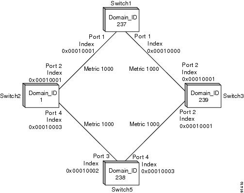
Figure 11-1 shows a single VSAN topology.

Figure 11-1 Single VSAN Topology

For the purpose of this example, assume that all interfaces are located in VSAN 1.

Troubleshooting FSPF Using Device Manager

To troubleshoot FSPF using Device Manager, follow these steps:


Step 1 Choose FC > Advanced > FSPF and select the LSDB LSRs tab to verify the link state records (LSRs) in the FSPF database.

The VSANId/ DomainId column shows the domain's view of the fabric topology.

The AdvDomainId column shows which domain is the owner of the LSR.

The Age value is a 16-bit counter starting at 0x0000, incremented by one for each switch during flooding and by one for each second held in the database. This field is used as a tie-breaker if incarnation numbers are the same.

The IncarnationNumber is a 32-bit value between 0x80000001 and 0x7FFFFFFF that is incremented by one each time the originating switch transmits an LSR. This is used before the Age value.

Step 2 Choose FC > Advanced > FSPF and select the LSDB Links tab to verify that each path is in the FSPF database.

Step 3 Choose FC > Advanced > FSPF and select the Interfaces tab to verify that the FSPF parameters are correct for each interface and verify that the AdminStatus is up.

The Cost column shows the cost of the path out of the interface.

The Intervals column shows the configured FSPF timers for this interface, which must match on both sides.

The State column shows the full or adjacent state if the interface has sent and received all database exchanges and required Acks. The port is now ready to route frames.

The Neighbors column shows FSPF neighbor information.

Step 4 Choose FC > Advanced > FSPF and select the Statistics or InterfaceStats tab to verify that there are no excessive errors present.


Troubleshooting FSPF Using the CLI

To troubleshoot FSPF using the CLI, follow these steps:


Step 1 Use the show fspf database vsan command to verify that each path is in the FSPF database.

switch1# show fspf database
FSPF Link State Database for VSAN 2 Domain 1 <-----1
LSR Type                = 1
Advertising domain ID   = 1  <-----2
LSR Age                 = 81 <-----3
LSR Incarnation number  = 0x80000098 <-----4
LSR Checksum            = 0x2cd3
Number of links         = 2
 NbrDomainId          IfIndex          NbrIfIndex          Link Type          Cost
--------------------------------------------------------------------------------------
237          0x00010002          0x00010001          1          1000 <-----5
238          0x00010003          0x00010002          1          1000 <-----6

FSPF Link State Database for VSAN 2 Domain 237 <-----------LSR for another switch
LSR Type                = 1
Advertising domain ID   = 237 <-----7
LSR Age                 = 185
LSR Incarnation number  = 0x8000000c
LSR Checksum            = 0xe0a2
Number of links         = 2
 NbrDomainId          IfIndex          NbrIfIndex          Link Type          Cost
--------------------------------------------------------------------------------------
239          0x00010000          0x00010003          1          1000 <-----8
  1          0x00010001          0x00010002          1          1000 <-----9

FSPF Link State Database for VSAN 2 Domain 238  <-----------LSR for another switch
LSR Type                = 1
Advertising domain ID   = 238
LSR Age                 = 1052
LSR Incarnation number  = 0x80000013
LSR Checksum            = 0xe294
Number of links         = 2
 NbrDomainId          IfIndex          NbrIfIndex          Link Type         Cost
--------------------------------------------------------------------------------------
239          0x00010003          0x00010001          1          1000
 1           0x00010002          0x00010003          1          1000

FSPF Link State Database for VSAN 2 Domain 239 <-----------LSR for another switch
LSR Type                = 1
Advertising domain ID   = 239
LSR Age                 = 1061
LSR Incarnation number  = 0x80000086
LSR Checksum            = 0x66ac
Number of links         = 4
 NbrDomainId          IfIndex          NbrIfIndex          Link Type          Cost
--------------------------------------------------------------------------------------
237          0x00010003          0x00010000          1          1000
238          0x00010001          0x00010003          1          1000

1. The domain 1 view of the fabric topology.

2. Domain 1 is owner of the LSR (link state record).

3. This is a 16-bit counter starting at 0x0000, incremented by one for each switch during flooding and by one for each second held in the database. This field is used as a tie-breaker if incarnation numbers are the same.

4. This is a 32-bit value between 0x80000001 and 0x7FFFFFFF. which is incremented by one each time the originating switch transmits an LSR. This is used before LSR Age.

5. The path to domainID 237, switch 1.

6. The path to domain ID 238, switch 5.

7. Switch 1, domain ID 237 is the owner.

8. The path to domain ID 239, switch 3.

9. The path to domain ID 1, switch 2.

Step 2 Use the show fspf vsan vsan-id interface command to verify that the FSPF parameters are correct for each interface and verify that the interface is in the FSPF active state.

switch1# show fspf vsan 2 interface fc1/2 
FSPF interface fc1/2 in VSAN 2
FSPF routing administrative state is active <-----1
Interface cost is 1000  <-----2
Timer intervals configured, Hello 20 s, Dead 80 s, Retransmit 5 s <-----3
FSPF State is FULL <-----4
Neighbor Domain Id is 1, Neighbor Interface index is 0x00010002 <-----5
Statistics counters : 
   Number of packets received : LSU  46  LSA  24  Hello 103  Error packets 0   
   Number of packets transmitted : LSU  24  LSA  45  Hello 104  Retransmitted LSU  0 
   Number of times inactivity timer expired for the interface = 0 

This displays the number of packets; Hellos should be received every 20 seconds.

1. FSPF routing is active.

2. The cost of the path out this interface.

3. The configured FSPF timers for this interface, which must match on both sides.

4. Either Full State or Adjacent. Sent and received all database exchanges and required Acks. Port is now ready to route frames.

5. FSPF neighbor information.

Step 3 Use the show fspf internal route vsan command to verify that all Fibre Channel routes are available.


Note To issue commands with the internal keyword, you must have an account that is a member of the network-admin group.


switch1# show fspf internal route vsan 2
FSPF Unicast Routes 
---------------------------
 VSAN     Number          Dest Domain          Route Cost          Next hops
----------------------------------------------------------------------------------------
1                   0x01(1)                    1000                  fc1/2
1                   0xEF(239)                  1000                  fc1/1
1                   0xED(238)                  2000                  fc1/1
                                                                     fc1/2

This shows the total cost of all links.

The next hop (238) has two interfaces. This indicates that both paths will be used during load sharing. Up to sixteen paths can be used by FSPF with a Cisco MDS 9000 Family switch.


With the implementation of VSANs used with Cisco MDS 9000 Family switches, a separate instance of FSPF runs within each VSAN, and each instance is independent of the others. For this reason, FSPF issues affecting one VSAN have no effect on FSPF running in other VSANs.


Note For all FSPF configuration statements and diagnostic commands, if the vsan keyword is not specified, VSAN 1 is used by default. When making configuration changes or issuing diagnostic commands in a multi-VSAN environment, be sure to explicitly specify the target VSAN by including the vsan keyword in the statement or command


Loss of Two-Way Communication

If FSPF is misconfigured, then the switches will not reach the "two-way" state.

The following events occur when two-way communication is lost:

The port enters Init state and removes its neighbor's domain ID from the Recipient Domain ID field and inserts 0xFFFFFFFF.

FSPF removes the Inter-Switch Link (ISL) from the topology database.

New link state records (LSRs) are flooded to adjacent switches to notify them that the FSPF database has changed.

Symptom    Traffic is not being routed through the fabric.

Table 11-17 Traffic Is not Being Routed Through the Fabric

Symptom
Possible Cause
Solution

Traffic is not being routed through the fabric.

FSPF hello interval misconfigured.

See the "Resolving a Wrong Hello Interval on an ISL Using Device Manager" section or the "Resolving a Wrong Hello Interval on an ISL Using the CLI" section.

FSPF retransmit time misconfigured.

See the "Resolving a Mismatched Retransmit Interval on an ISL Using Device Manager" section or the "Resolving a Mismatched Retransmit Interval on an ISL Using the CLI" section.

FSPF dead interval misconfigured.

See the "Resolving a Mismatch in Dead Intervals on an ISL Using Fabric Manager" section or the "Resolving a Mismatch in Dead Intervals on an ISL Using the CLI" section.

There is a region mismatch on the switch.

See the "Resolving a Region Mismatch Using Fabric Manager" section or the "Resolving a Region Mismatch Using the CLI" section.


Resolving a Wrong Hello Interval on an ISL Using Device Manager

To resolve a wrong hello interval on an ISL using Device Manager, follow these steps:


Step 1 Choose FC > Advanced > FSPF and select the Interfaces tab to verify that the FSPF parameters are correct for each interface and check the Hello interval column and the State column.

The Intervals column shows the configured FSPF timers for this interface, which must match on both sides.

The State column shows the full or adjacent state if the interface has sent and received all database exchanges and required Acks. The port is now ready to route frames.

Step 2 Repeat Step 1 to determine the value of the hello interval on the adjacent switch.

Step 3 Fill in the Hello field to change the hello interval and click Apply.


Resolving a Wrong Hello Interval on an ISL Using the CLI

To resolve a wrong hello interval on an ISL using the CLI, follow these steps:


Step 1 Use the debug fspf all command and look for wrong hello interval messages.

switch1# debug fspf all
Jan  5 00:28:14 fspf: Wrong hello interval for packet on interface 100f000 in VSAN 1 
Jan  5 00:28:14 fspf: Error in processing hello packet ,  error code = 4  

Tip We recommend that you open a second Telnet or SSH session before entering any debug commands. If the debug output overwhelms the current session, you can use the second session to enter the undebug all command to stop the debug message output.


Step 2 Use the undebug all command to turn off debugging.

Step 3 Use the show fspf internal route vsan command to show FSPF information.


Note To issue commands with the internal keyword, you must have an account that is a member of the network-admin group.


switch1# show fspf internal route vsan 1
FSPF Unicast Routes 
---------------------------
 VSAN Number   Dest Domain   Route Cost    Next hops
----------------------------------------------------------------------
1              0xEF(239)      1000          fc1/1 <-----1
1              0xED(238)      2000          fc1/1 
1              0x01(1)        3000          fc1/1 <-----2

1. There is no second path to domain 238, through domain 1 switch 2.

2. There is no direct path to domain 1 switch 2; traffic must travel through three ISLs. This is based on the route cost column.


Step 4 Use the show fspf vsan vsan-id interface command to view the FSFP configuration.

switch1# show fspf vsan 1 interface fc1/16
FSPF interface fc1/16 in VSAN 1
FSPF routing administrative state is active
Interface cost is 500
Timer intervals configured, Hello 5 s, Dead 80 s, Retransmit 5 s <-----1
FSPF State is INIT <-----2
Statistics counters :
   Number of packets received : LSU  0  LSA  0  Hello 2  Error packets 1 
   Number of packets transmitted : LSU  0  LSA  0  Hello 4  Retransmitted LSU  0
Number of times inactivity timer expired for the interface = 0

1. The Hello timer is not set to the default, so you should check the neighbor configuration to make sure it matches.

2. FSPF is not in FULL state, indicating a problem.

Step 5 Repeat Step 4 to determine the value of the Hello timer on the adjacent switch.

switch2# show fspf v 1 interface fc2/16
FSPF interface fc2/16 in VSAN 1
FSPF routing administrative state is active
Interface cost is 500
Timer intervals configured, Hello 20 s, Dead 80 s, Retransmit 5 s <-----1
FSPF State is INIT <-----2
Statistics counters :
   Number of packets received : LSU  0  LSA  0  Hello 2  Error packets 1 
   Number of packets transmitted : LSU  0  LSA  0  Hello 4  Retransmitted LSU  0
   Number of times inactivity timer expired for the interface = 0

1. The neighbor FSPF Hello interval is set to the default (20 seconds).

2. FSPF is not in full state, indicating a problem.

Step 6 Use the interface command and then the fspf hello-interval command in interface mode to change the default Hello interval.


Resolving a Mismatched Retransmit Interval on an ISL Using Device Manager

To resolve a mismatched retransmit interval on an ISL using Device Manager, follow these steps:


Step 1 Choose FC > Advanced > FSPF and select the Interfaces tab to verify that the FSPF parameters are correct for each interface and check the Retransmit interval column and the State column.

The Intervals column shows the configured FSPF timers for this interface, which must match on both sides.

The State column shows the full or adjacent state if the interface has sent and received all database exchanges and required Acks. The port is now ready to route frames.

Step 2 Repeat Step 1 to determine the value of the retransmit interval on the adjacent switch.

Step 3 Fill in the Retransmit field to change the retransmit interval and click Apply.


Resolving a Mismatched Retransmit Interval on an ISL Using the CLI

To resolve a mismatched retransmit interval on an ISL using the CLI, follow these steps:


Step 1 Use the show fspf vsan vsan-id interface command to view the FSFP configuration.

switch1# show fspf vsan 1 interface fc1/16
FSPF interface fc1/16 in VSAN 1
FSPF routing administrative state is active
Interface cost is 500
Timer intervals configured, Hello 5 s, Dead 80 s, Retransmit 10 s <-----1
FSPF State is INIT <-----2
Statistics counters :
   Number of packets received : LSU  0  LSA  0  Hello 2  Error packets 1 
   Number of packets transmitted : LSU  0  LSA  0  Hello 4  Retransmitted LSU  0
Number of times inactivity timer expired for the interface = 0

1. The retransmit interval is not set to the default, so you should check the neighbor configuration to make sure it matches.

2. FSPF is not in FULL state, indicating a problem.

Step 2 Repeat Step 1 to determine the value of the retransmit interval on the adjacent switch.

switch2# show fspf v 1 interface fc2/16
FSPF interface fc2/16 in VSAN 1
FSPF routing administrative state is active
Interface cost is 500
Timer intervals configured, Hello 20 s, Dead 80 s, Retransmit 5 s <-----1
FSPF State is INIT <-----2
Statistics counters :
   Number of packets received : LSU  0  LSA  0  Hello 2  Error packets 1 
   Number of packets transmitted : LSU  0  LSA  0  Hello 4  Retransmitted LSU  0
   Number of times inactivity timer expired for the interface = 0

1. The neighbor retransmit interval interval is set to the default (5 seconds).

2. FSPF is not in FULL state, indicating a problem.

Step 3 Use the interface command and then the fspf retransmit-interval command in interface mode to change the retransmit interval.


Resolving a Mismatch in Dead Intervals on an ISL Using Fabric Manager

To resolve a mismatch of dead intervals on an ISL using Fabric Manager, follow these steps:


Step 1 Choose FC > Advanced > FSPF and select the Interfaces tab to verify that the FSPF parameters are correct for each interface and check the Dead interval column and the State column.

The Intervals column shows the configured FSPF timers for this interface, which must match on both sides.

The State column shows the full or adjacent state if the interface has sent and received all database exchanges and required Acks. The port is now ready to route frames.

Step 2 Repeat Step 1 to determine the value of the dead interval on the adjacent switch.

Step 3 Fill in the Dead field to change the dead interval and click Apply.


Resolving a Mismatch in Dead Intervals on an ISL Using the CLI

To identify a mismatch in dead intervals on an ISL, follow these steps:


Step 1 Use the debug fspf all command and look for wrong dead interval messages.

switch1# debug fspf all
Jan  5 00:28:14 fspf: Wrong dead interval for packet on interface 100f000 in VSAN 1 
Jan  5 00:28:14 fspf: Error in processing hello packet ,  error code = 4  

Tip We recommend that you open a second Telnet or SSH session before entering any debug commands. If the debug output overwhelms the current session, you can use the second session to enter the undebug all command to stop the debug message output.


Step 2 Use the undebug all command to turn off debugging.

Step 3 Use the show fspf vsan vsan-id interface command to show FSPF information.


Note To issue commands with the internal keyword, you must have an account that is a member of the network-admin group.


switch1# show fspf vsan 1 interface fc1/16
FSPF interface fc1/16 in VSAN 1
FSPF routing administrative state is active
Interface cost is 500
Timer intervals configured, Hello 20 s, Dead 95 s, Retransmit 5 s <-----1
FSPF State is INIT <-----2
xStatistics counters :
   Number of packets received : LSU  0  LSA  0  Hello 2  Error packets 1 
   Number of packets transmitted : LSU  0  LSA  0  Hello 4  Retransmitted LSU  0
   Number of times inactivity timer expired for the interface = 0

1. The dead timer is not set to the default, so you should check the neighbor configuration.

2. FSPF is not in full state, which indicates a problem.

Step 4 Use the interface comma nd and then the fspf dead-interval command in interface mode to change the dead interval.


Resolving a Region Mismatch Using Fabric Manager

To identify a region mismatch problem on a switch using Fabric Manager, follow these steps:


Step 1 Choose FC > Advanced > FSPF and select the General tab to verify the RegionId.

Step 2 Repeat Step 1 to determine the value of the region on the adjacent switch.

Step 3 Fill in the RegionId field to change the region and click Apply.


Resolving a Region Mismatch Using the CLI

To identify a region mismatch problem on a switch using the CLI, follow these steps:


Step 1 Use the show fspf vsan command to display the currently configured region in a VSAN.

switch# show fspf vsan 99

FSPF routing for VSAN 99 
FSPF routing administration status is enabled 
FSPF routing operational status is UP 
It is an intra-domain router 
Autonomous region is 0    /* This is the region */ 
SPF hold time is 0 msec 
MinLsArrival = 1000 msec , MinLsInterval = 5000 msec 
Local Domain is 0x78(120) 
Number of LSRs = 2, Total Checksum = 0x000133de

Step 2 Use the debug fspf all command and look for nonexistent region messages.

switch1# debug fspf all
Jan  5 00:39:31 fspf: FC2 packet received for non existent  region 0 in VSAN 1 <-----1
Jan  5 00:39:33 fspf: FC2 packet received for non existent  region 0 in VSAN 1  
Jan  5 00:39:45 fspf: Interface fc1/1 in VSAN 1 : Event INACTIVITY , State change INIT -> 
INIT  
Jan  5 00:39:45 fspf: Interface fc1/2 in VSAN 1 : Event INACTIVITY , State change INIT -> 
INIT <-----2

1. The neighbor switch advertising region is 0.

2. FSPF is in init state for each ISL.


Tip We recommend that you open a second Telnet or SSH session before entering any debug commands. If the debug output overwhelms the current session, you can use the second session to enter the undebug all command to stop the debug message output.


Step 3 Use the undebug all command to turn off debugging.

Step 4 Use the show fspf command to show FSPF configuration and check the autonomous region.

Step 5 Use the fspf config vsan command to enter the FSPF configuration mode and use the region command to change the region.


The region must match on all switches in the VSAN.