Table Of Contents
Troubleshooting IPsec
Overview
IPsec Compatibility
Supported IPsec and IKE Algorithms for Microsoft Windows and Linux Platforms
IKE Allowed Transforms
IPsec Allowed Transforms
Initial Troubleshooting Checklist
Common Troubleshooting Tools in Fabric Manager
Common Troubleshooting Commands in the CLI
IPsec Issues
Verifying IKE Configuration Compatibility
Verifying IPsec Configuration Compatibility Using Fabric Manager
Verifying IPsec Configuration Compatibility Using the CLI
Verifying Security Policy Databases Compatibility
Verifying Interface Status Using Fabric Manager
Verifying Interface Status Using the CLI
Verifying Security Associations
Security Associations Do Not Re-Key
Clearing Security Associations
Debugging the IPsec Process
Debugging the IKE Process
Obtaining Statistics from the IPsec Process
Troubleshooting IPsec
This chapter describes how to troubleshoot IP security (IPsec) and Internet Key Exchange (IKE) encryption in the Cisco MDS 9000 Family. It includes the following sections:
•Overview
•Initial Troubleshooting Checklist
•IPsec Issues
Overview
The IPsec protocol is a framework of open standards that provides data confidentiality, data integrity, and data authentication between participating peers. It was developed by the Internet Engineering Task Force (IETF). IPsec provides security services at the IP layer, including protecting one or more data flows between a pair of hosts, between a pair of security gateways, or between a security gateway and a host. IPsec is supported for iSCSI and FCIP using IKE and Encapsulated Security Protocol (ESP) in tunnel mode.
This section contains the following topics:
•IPsec Compatibility
•Supported IPsec and IKE Algorithms for Microsoft Windows and Linux Platforms
•IKE Allowed Transforms
•IPsec Allowed Transforms
IPsec Compatibility
IPsec features are compatible with the following Cisco MDS 9000 Family hardware:
•Cisco 14/2-port Multiprotocol Services (MPS-14/2) modules in Cisco MDS 9200 switches or Cisco MDS 9500 directors
•Cisco MDS 9216i Switch with the MPS-14/2 capability in the integrated supervisor module. Refer to the Cisco MDS 9200 Series Hardware Installation Guide for more information on the Cisco MDS 9216i Switch.
•The IPsec feature is not supported on the management interface.
Note IPsec and IKE are not supported by the Cisco Fabric Switch HP c-Class BladeSystem and the Cisco Fabric Switch for IBM BladeCenter.
IPsec features are compatible with the following fabric setup:
•Two connected Cisco MDS 9200 switches or Cisco MDS 9500 directors running Cisco MDS SAN-OS Release 2.0(1b) or later.
•A Cisco MDS 9200 switches or Cisco MDS 9500 directors running Cisco MDS SAN-OS Release 2.0(1b) or later connected to any IPsec compliant device.
•The following features are not supported in the Cisco SAN-OS implementation of the IPsec feature:
–Authentication Header (AH).
–Transport mode.
–Security association bundling.
–Manually configuring security associations.
–Per host security association option in a crypto map.
–Security association idle timeout
–Dynamic crypto maps.
–IPv6
Note Any reference to crypto maps in this document only refers to static crypto maps.
•For IPsec to interoperate effectively with Microsoft iSCSI initiators, specify the TCP protocol and the local iSCSI TCP port number (default 3260) in the IPv4-ACL. This configuration ensures the speedy recovery of encrypted iSCSI sessions following disruptions such as Gigabit Ethernet interfaces shutdowns, VRRP switchovers, and port failures. The following example of a IPv4-ACL entry shows that the MDS switch IPv4 address is 10.10.10.50 and remote Microsoft host running encrypted iSCSI sessions is 10.10.10.16:
switch(config)# ip access-list aclmsiscsi2 permit tcp 10.10.10.50 0.0.0.0 range port
3260 3260 10.10.10.16 0.0.0.0
Note Cisco MDS IKEv2 will not interoperate with other IKEv2 implementations.
Supported IPsec and IKE Algorithms for Microsoft Windows and Linux Platforms
Table 22-2 lists the supported and verified settings for IPsec and IKE encryption authentication algorithms on the Microsoft Windows and Linux platforms.
Table 22-1 IPsec and IKE for Windows and Linux
Platform
|
IKE
|
IPsec
|
Microsoft iSCSI initiator, Microsoft IPsec implementation on Microsoft Windows 2000 platform
|
3DES, SHA-1 or MD5, DH group 2
|
3DES, SHA-1
|
Cisco iSCSI initiator, Free Swan IPsec implementation on Linux platform
|
3DES, MD5, DH group 1
|
3DES, MD5
|
IKE Allowed Transforms
Table 22-2 provides a list of allowed transform combinations for IKE.
Table 22-2 IKE Transform Configuration Parameters
Parameter
|
Accepted Values
|
Default Value
|
Encryption algorithm
|
56-bit DES-CBC
168-bit DES (3DES)
128-bit AES
|
3DES
|
Hash algorithm
|
SHA-1 (HMAC variant)
MD5 (HMAC variant)
|
SHA-1
|
Authentication method
|
Preshared keys
RSA signatures in digital certificates
|
Preshared keys
|
DH group identifier
|
768-bit DH
1024-bit DH
1536-bit DH
|
768-bit DH (1)
|
IPsec Allowed Transforms
Table 22-3 provides a list of allowed transform combinations for IPsec.
Table 22-3 IPsec Transform Configuration Parameters
Parameter
|
Accepted Values
|
Encryption algorithm
|
56-bit DES-CBC
168-bit DES
128-bit AES-CBC
128-bit AES-CTR1
256-bit AES-CBC
256-bit AES-CTR1
|
Hash/authentication algorithm1 (optional)
|
SHA-1 (HMAC variant)
MD5 (HMAC variant)
AES-XCBC-MAC
|
Initial Troubleshooting Checklist
Begin troubleshooting IPsec issues by checking the following issues:
Checklist
|
Check off
|
Verify licensing requirements. See Cisco MDS 9000 Family Fabric Manager Configuration Guide.
|
|
Verify that IKE has been configured for IPsec.
|
|
Verify the digital certificates configuration if it is enabled for IPsec. See Chapter 24, "Troubleshooting Digital Certificates."
|
|
Verify that there are matching IKE policies defined at each peer.
|
|
Verify that you have refreshed SAs after any IKEv2 reconfiguration.
|
|
Verify that you have configured mirror crypto map ACLs at the peer for every crypto map ACL configured locally.
|
|
Common Troubleshooting Tools in Fabric Manager
Choose Switches > Security > IPsec to access IPsec.
Choose Switches > Security > IKE to access IKE.
Common Troubleshooting Commands in the CLI
Use the following commands to troubleshoot IPsec issues:
•show crypto transform-set domain ipsec
•show crypto global domain ipsec
•show crypto global domain ipsec security-association lifetime
•show crypto sad domain ipsec
Use the following internal commands to gather more information for IPsec issues:
•show ipsec internal error—Displays a log of error history.
•show ipsec internal mem-stats detail—Displays memory usage.
•show ipsec internal event-history msgs —Displays a log of message history.
Use the following commands to gather information from the hardware accelerator:
•show ipsec internal crypto-accelerator interface gigabit 2/1 sad inbound/outbound sa-index— Displays detailed information of an SA from the hardware accelerator.
•show ipsec internal crypto-accelerator interface gigabit 2/1 stats—Displays detailed information per interface from the hardware accelerator.
IPsec Issues
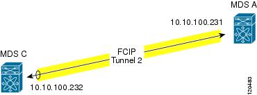
This section provides the procedures required to troubleshoot IKE and IPsec issues in an FCIP configuration. Figure 22-1 shows a simple FCIP configuration where FCIP Tunnel 2 carries encrypted data between switches MDS A and MDS C.
Figure 22-1 Simple FCIP Configuration
This section includes the following topics:
•Verifying IKE Configuration Compatibility
•Verifying IPsec Configuration Compatibility Using Fabric Manager
•Verifying IPsec Configuration Compatibility Using the CLI
•Verifying Security Policy Databases Compatibility
•Verifying Interface Status Using Fabric Manager
•Verifying Interface Status Using the CLI
•Verifying Security Associations
•Security Associations Do Not Re-Key
•Clearing Security Associations
•Debugging the IPsec Process
•Debugging the IKE Process
•Obtaining Statistics from the IPsec Process
Verifying IKE Configuration Compatibility
To verify the compatibility of the IKE configurations of MDS A and MDS C shown in Figure 22-1, follow these steps:
Step 1 Ensure that the preshared keys are identical on each switch. Use the show crypto ike domain ipsec key CLI command on both switches. Command outputs for the configuration shown in Figure 22-1 follow:
MDSA# show crypto ike domain ipsec key
key ctct address 10.10.100.232
MDSC# show crypto ike domain ipsec key
key ctct address 10.10.100.231
Step 2 Ensure that at least one matching policy that has the same encryption algorithm, hash algorithm, and Diffie-Hellman (DH) group is configured on each switch. Issue the show crypto ike domain ipsec policy command on both switches. Example command outputs for the configuration shown in Figure 22-1 follow:
MDSA# show crypto ike domain ipsec policy
Priority 1, auth pre-shared, lifetime 86300 secs, encryption 3des, hash md5, DH group 1
MDSC# show crypto ike domain ipsec policy
Priority 1, auth pre-shared, lifetime 86300 secs, encryption 3des, hash md5, DH group 1
Verifying IPsec Configuration Compatibility Using Fabric Manager
To verify the compatibility of the IPsec configurations of MDS A and MDS C shown in Figure 22-1 using Fabric manager, follow these steps:
Step 1 Choose Switches > Security > IPSEC and select the CryptoMap Set Entry tab. Verify that the Peer Address, IpFilter, Lifetime, and PFS fields match for MDS A and MDS C.
Step 2 Select the Transform Set tab and verify that the transform set on both switches match.
Step 3 Select the Interfaces tab and verify that the crypto map set is applied to the correct interface on both switches.
Step 4 In Device Manager, choose IP > ACLs and verify that the ACLs used in the crypto map in Step 1 are compatible on both switches.
Verifying IPsec Configuration Compatibility Using the CLI
To verify the compatibility of the IPsec configurations of MDS A and MDS C shown in Figure 22-1 using the CLI, follow these steps:
Step 1 Use the show crypto map domain ipsec command and the show crypto transform-set domain ipsec command. The following command outputs display the fields discussed in Step 2 through Step 7.
MDSA# show crypto map domain ipsec
Crypto Map "cmap-01" 1 ipsec
Peer = 10.10.100.232
IP ACL = acl1
permit ip 10.10.100.231 255.255.255.255 10.10.100.232 255.255.255.255
Security Association Lifetime: 3000 gigabytes/120 seconds
PFS (Y/N): Y
PFS Group: group5
Interface using crypto map set cmap-01:
MDSC# show crypto map domain ipsec
Crypto Map "cmap-01" 1 ipsec
Peer = 10.10.100.231
IP ACL = acl1
permit ip 10.10.100.232 255.255.255.255 10.10.100.231 255.255.255.255
Security Association Lifetime: 3000 gigabytes/120 seconds
PFS (Y/N): Y
PFS Group: group5
Interface using crypto map set cmap-01:
MDSA# show crypto transform-set domain ipsec
Transform set:tfs-01 {esp-3des null}
Transform set:tfs-02 {esp-3des esp-md5-hmac}
Transform set:ipsec_default_transform_set {esp-aes 128 esp-sha1-hmac}
MDSC# show crypto transform-set domain ipsec
Transform set:tfs-01 {esp-3des null}
Transform set:tfs-02 {esp-3des esp-md5-hmac}
Transform set:ipsec_default_transform_set {esp-aes 128 esp-sha1-hmac}
Step 2 Ensure that the ACLs are compatible in the show crypto map domain ipsec command outputs for both switches.
Step 3 Ensure that the peer configuration is correct in the show crypto map domain ipsec command outputs for both switches.
Step 4 Ensure that the transform sets are compatible in the show crypto transform-set domain ipsec command outputs for both switches.
Step 5 Ensure that the PFS settings in the show crypto map domain ipsec command outputs are configured the same on both switches.
Step 6 Ensure that the security association (SA) lifetime settings in the show crypto map domain ipsec command outputs are large enough to avoid excessive re-keys (the default settings ensure this).
Step 7 Ensure that the crypto map set is applied to the correct interface in the show crypto map domain ipsec command outputs for both switches.
Verifying Security Policy Databases Compatibility
To verify that the security policy databases (SPDs) are compatible on both switches, follow these steps:
Step 1 Issue the show crypto spd domain ipsec command on both switches to display the SPD. The command outputs follow:
MDSA# show crypto spd domain ipsec
Policy Database for interface:GigabitEthernet7/1, direction:Both
# 0: deny udp any port eq 500 any <-----------Clear test policies for IKE
# 1: deny udp any any port eq 500 <-----------Clear test policies for IKE
# 2: permit ip 10.10.100.231 255.255.255.255 10.10.100.232 255.255.255.255
# 127: deny ip any any <------------Clear test policy for all other traffic
MDSC# show crypto spd domain ipsec
Policy Database for interface:GigabitEthernet1/2, direction:Both
# 0: deny udp any port eq 500 any
# 1: deny udp any any port eq 500
# 2: permit ip 10.10.100.232 255.255.255.255 10.10.100.231 255.255.255.255
Step 2 Issue the show ipsec internal crypto-accelerator interface gigabitethernet slot/port spd inbound command on both switches to display SPD information from the crypto-accelerator.
Note To issue commands with the internal keyword, you must have an account that is a member of the network-admin group.
The example command outputs follow:
MDSA# show ipsec internal crypto-accelerator interface gigabitethernet 7/1 spd inbound
Destination IP Address :*
Source port :500, Destination port :* Protocol UDP
Physical port:0/0, Vlan_id:0/0
Destination IP Address :*
Source port :*, Destination port :500 Protocol UDP
Physical port:0/0, Vlan_id:0/0
Source IP Address :10.10.100.232/255.255.255.255
Destination IP Address :10.10.100.231/255.255.255.255
Source port :*, Destination port :* Protocol *
Physical port:0/1, Vlan_id:0/4095
Destination IP Address :*
Source port :*, Destination port :* Protocol *
Physical port:0/0, Vlan_id:0/0
MDSC# show ipsec internal crypto-accelerator interface gigabitethernet 1/2 spd inbound
Destination IP Address :*
Source port :500, Destination port :* Protocol UDP
Physical port:0/0, Vlan_id:0/0
Destination IP Address :*
Source port :*, Destination port :500 Protocol UDP
Physical port:0/0, Vlan_id:0/0
Source IP Address :10.10.100.231/255.255.255.255
Destination IP Address :10.10.100.232/255.255.255.255
Source port :*, Destination port :* Protocol *
Physical port:1/1, Vlan_id:0/4095
Destination IP Address :*
Source port :*, Destination port :* Protocol *
Physical port:0/0, Vlan_id:0/0
Verifying Interface Status Using Fabric Manager
To verify the status of the interfaces using Fabric Manager, follow these steps:
Step 1 Choose Switches > Interfaces > GigabitEthernet to verify that the interfaces are up and their IP addresses are correct.
Step 2 Choose ISLs > FCIP and select the Tunnels tab. Verify that each interface is using the correct profile, the peer internet addresses are configured correctly, and the FCIP tunnels are compatible.
Verifying Interface Status Using the CLI
To verify the status of the interfaces using the CLI, follow these steps:
Step 1 Issue the show interface gigabitethernet command on both switches. Verify that the interfaces are up and their IP addresses are correct. Issue the no shutdown command if necessary. The command outputs follow:
MDSA# show interface gigabitethernet 7/1
GigabitEthernet7/1 is up
Hardware is GigabitEthernet, address is 0005.3001.804e
Internet address is 10.10.100.231/24
Auto-Negotiation is turned on
5 minutes input rate 7728 bits/sec, 966 bytes/sec, 8 frames/sec
5 minutes output rate 7968 bits/sec, 996 bytes/sec, 8 frames/sec
7175 packets input, 816924 bytes
0 multicast frames, 0 compressed
0 input errors, 0 frame, 0 overrun 0 fifo
7285 packets output, 840018 bytes, 0 underruns
0 output errors, 0 collisions, 0 fifo
MDSC# show interface gigabitethernet 1/2
GigabitEthernet1/2 is up
Hardware is GigabitEthernet, address is 0005.3001.7f0f
Internet address is 10.10.100.232/24
Auto-Negotiation is turned on
5 minutes input rate 7528 bits/sec, 941 bytes/sec, 8 frames/sec
5 minutes output rate 7288 bits/sec, 911 bytes/sec, 8 frames/sec
7209 packets input, 835518 bytes
0 multicast frames, 0 compressed
0 input errors, 0 frame, 0 overrun 0 fifo
7301 packets output, 827630 bytes, 0 underruns
0 output errors, 0 collisions, 0 fifo
Step 2 Issue the show interface fcip command on both switches. Verify that each interface is using the correct profile, the peer internet addresses are configured correctly, and the FCIP tunnels are compatible. Issue the no shutdown command if necessary. The command outputs follow:
MDSA# show interface fcip 1
Hardware is GigabitEthernet
Port WWN is 21:90:00:0d:ec:02:64:80
Peer port WWN is 20:14:00:0d:ec:08:5f:c0
Admin port mode is auto, trunk mode is on
Trunk vsans (admin allowed and active) (1,100,200,302-303,999,3001-3060)
Trunk vsans (isolated) (100,200,302-303,999,3001-3060)
Trunk vsans (initializing) ()
Using Profile id 1 (interface GigabitEthernet7/1)
Peer Internet address is 10.10.100.232 and port is 3225
FCIP tunnel is protected by IPSec
Write acceleration mode is off
Tape acceleration mode is off
Tape Accelerator flow control buffer size is automatic
IP Compression is disabled
Special Frame is disabled
Maximum number of TCP connections is 2
QOS control code point is 0
TCP Connection Information
Control connection:Local 10.10.100.231:3225, Remote 10.10.100.232:65492
Data connection:Local 10.10.100.231:3225, Remote 10.10.100.232:65494
20 Attempts for active connections, 0 close of connections
Current retransmission timeout is 200 ms
Round trip time:Smoothed 2 ms, Variance:3
Advertized window:Current:118 KB, Maximum:14 KB, Scale:6
Peer receive window:Current:128 KB, Maximum:128 KB, Scale:6
Congestion window:Current:14 KB, Slow start threshold:204 KB
Current Send Buffer Size:14 KB, Requested Send Buffer Size:0 KB
5 minutes input rate 2960 bits/sec, 370 bytes/sec, 4 frames/sec
5 minutes output rate 3184 bits/sec, 398 bytes/sec, 4 frames/sec
3628 frames input, 340644 bytes
3610 Class F frames input, 338396 bytes
18 Class 2/3 frames input, 2248 bytes
0 Error frames timestamp error 0
3624 frames output, 359140 bytes
3608 Class F frames output, 357332 bytes
16 Class 2/3 frames output, 1808 bytes
MDSC# show interface fcip 1
Hardware is GigabitEthernet
Port WWN is 20:14:00:0d:ec:08:5f:c0
Peer port WWN is 21:90:00:0d:ec:02:64:80
Admin port mode is auto, trunk mode is on
Trunk vsans (admin allowed and active) (1)
Trunk vsans (isolated) ()
Trunk vsans (initializing) ()
Using Profile id 1 (interface GigabitEthernet1/2)
Peer Internet address is 10.10.100.231 and port is 3225
FCIP tunnel is protected by IPSec
Write acceleration mode is off
Tape acceleration mode is off
Tape Accelerator flow control buffer size is automatic
IP Compression is disabled
Special Frame is disabled
Maximum number of TCP connections is 2
QOS control code point is 0
TCP Connection Information
Control connection:Local 10.10.100.232:65492, Remote 10.10.100.231:3225
Data connection:Local 10.10.100.232:65494, Remote 10.10.100.231:3225
22 Attempts for active connections, 1 close of connections
Current retransmission timeout is 200 ms
Round trip time:Smoothed 2 ms, Variance:3
Advertized window:Current:128 KB, Maximum:14 KB, Scale:6
Peer receive window:Current:118 KB, Maximum:118 KB, Scale:6
Congestion window:Current:15 KB, Slow start threshold:204 KB
Current Send Buffer Size:14 KB, Requested Send Buffer Size:0 KB
5 minutes input rate 3192 bits/sec, 399 bytes/sec, 4 frames/sec
5 minutes output rate 2960 bits/sec, 370 bytes/sec, 4 frames/sec
3626 frames input, 359324 bytes
3610 Class F frames input, 357516 bytes
16 Class 2/3 frames input, 1808 bytes
0 Error frames timestamp error 0
3630 frames output, 340828 bytes
3612 Class F frames output, 338580 bytes
18 Class 2/3 frames output, 2248 bytes
Verifying Security Associations
To verify security associations (SAs), follow these steps:
Step 1 Issue the show crypto sad domain ipsec command to verify the current peer, mode, and inbound and outbound index of each switch. The example command outputs follow:
MDSA# show crypto sad domain ipsec
interface:GigabitEthernet7/1
Crypto map tag:cmap-01, local addr. 10.10.100.231
local ident (addr/mask):(10.10.100.231/255.255.255.255)
remote ident (addr/mask):(10.10.100.232/255.255.255.255)
current_peer:10.10.100.232
local crypto endpt.:10.10.100.231, remote crypto endpt.:10.10.100.232
mode:tunnel, crypto algo:esp-3des, auth algo:esp-md5-hmac
current outbound spi:0x822a202 (136487426), index:1
lifetimes in seconds::3600
lifetimes in bytes::483183820800
current inbound spi:0x38147002 (940863490), index:1
lifetimes in seconds::3600
lifetimes in bytes::483183820800
MDSC# show crypto sad domain ipsec
interface:GigabitEthernet1/2
Crypto map tag:cmap-01, local addr. 10.10.100.232
local ident (addr/mask):(10.10.100.232/255.255.255.255)
remote ident (addr/mask):(10.10.100.231/255.255.255.255)
current_peer:10.10.100.231
local crypto endpt.:10.10.100.232, remote crypto endpt.:10.10.100.231
mode:tunnel, crypto algo:esp-3des, auth algo:esp-md5-hmac
current outbound spi:0x38147002 (940863490), index:513
lifetimes in seconds::3600
lifetimes in bytes::483183820800
current inbound spi:0x822a202 (136487426), index:513
lifetimes in seconds::3600
lifetimes in bytes::483183820800
Step 2 The SA index can be used to look at the SA in the crypto-accelerator. Issue the show ipsec internal crypto-accelerator interface gigabitethernet slot/port sad [inbound | outbound] sa-index command to display the inbound or outbound SA information. The hard limit bytes and soft limit bytes fields display the lifetime in bytes. The hard limit expiry secs and the soft limit expiry secs fields display the lifetime in seconds.
Note To issue commands with the internal keyword, you must have an account that is a member of the network-admin group.
The command outputs follow:
MDSA# show ipsec internal crypto-accelerator interface gigabitethernet 7/1 sad inbound 1
sw172.22.48.91# show ipsec internal crypto-accelerator interface gigabitethernet 7/1 sad
inbound 1
Mode :Tunnel, flags:0x492300000000000
Encrypt algorithm is DES/3DES
Source ip address 10.10.100.232/255.255.255.255
Destination ip address 10.10.100.231/255.255.255.255
Physical port 0, mask:0x1
Source port no 0 mask:0x0
Hard limit 483183820800 bytes
Soft limit 401042571264 bytes
SA byte count 845208 bytes <----Elapsed traffic
SA user byte count 845208 bytes <----Elapsed traffic
Error count:auth:0, pad:0, replay:0
Hard limit expiry 1100652419 secs (since January 1, 1970), remaining 219 7 secs
Soft limit expiry 1100652386 secs (since January 1, 1970), remaining 216 4 secs
Antireplay window:0xffffffff.0xffffffff.0xffffffff.0xffffffff
MDSC# show ipsec internal crypto-accelerator interface gigabitethernet 1/2 sad inbound 513
Mode :Tunnel, flags:0x492300000000000
Encrypt algorithm is DES/3DES
Source ip address 10.10.100.231/255.255.255.255
Destination ip address 10.10.100.232/255.255.255.255
Physical port 1, mask:0x1
Source port no 0 mask:0x0
Hard limit 483183820800 bytes
Soft limit 420369924096 bytes
SA byte count 873056 bytes <----Elapsed traffic
SA user byte count 873056 bytes <----Elapsed traffic
Error count:auth:0, pad:0, replay:0
Packet count 7137
Hard limit expiry 1100652419 secs (since January 1, 1970), remaining 214 1 secs
Soft limit expiry 1100652394 secs (since January 1, 1970), remaining 211 6 secs
Antireplay window:0xffffffff.0xffffffff.0xffffffff.0xffffffff
MDSA# show ipsec internal crypto-accelerator interface gigabitethernet 7/1 sad outbound 1
SPI 136487426 (0x822a202), MTU 1400, MTU_delta 4
Mode :Tunnel, flags:0x92100000000000
Tunnel options index:0, ttl:0x40, flags:0x1
Encrypt algorithm is DES/3DES
Tunnel source ip address 10.10.100.231
Tunnel destination ip address 10.10.100.232
Hard limit 483183820800 bytes
Soft limit 376883380224 bytes
SA byte count 874544 bytes <----Elapsed traffic
SA user byte count 874544 bytes <----Elapsed traffic
Hard limit expiry 1100652419 secs (since January 1, 1970), remaining 208 9 secs
Soft limit expiry 1100652384 secs (since January 1, 1970), remaining 205 4 secs
Outbound MAC table index:1
MDSC# show ipsec internal crypto-accelerator interface gigabitethernet 1/2 sad outbound
513
SPI 940863490 (0x38147002), MTU 1400, MTU_delta 4
Mode :Tunnel, flags:0x92100000000000
Tunnel options index:0, ttl:0x40, flags:0x1
Encrypt algorithm is DES/3DES
Tunnel source ip address 10.10.100.232
Tunnel destination ip address 10.10.100.231
Hard limit 483183820800 bytes
Soft limit 449360953344 bytes
SA byte count 855648 bytes <----Elapsed traffic
SA user byte count 855648 bytes <----Elapsed traffic
Hard limit expiry 1100652419 secs (since January 1, 1970), remaining 206 4 secs
Soft limit expiry 1100652397 secs (since January 1, 1970), remaining 204 2 secs
Outbound MAC table index:125
Security Associations Do Not Re-Key
A lifetime counter (in seconds and bytes) is maintained as soon as an SA is created. When the time limit expires, the SA is no longer operational and is automatically renegotiated (re-keyed) if traffic is present. If there is no traffic, the SA will not be re-keyed and the tunnel will go down.
The re-key operation starts when the soft lifetime expires. That happens approximately 20 to 30 seconds before the time-based lifetime expires, or when approximately 10 to 20 percent of the bytes are remaining in the bytes-based lifetime.
To troubleshoot this problem, follow these steps:
Step 1 Verify that traffic was flowing when the soft SA lifetime expired.
Step 2 Verify that the configurations are still compatible.
Clearing Security Associations
To clear a specific SA, obtain the SA index value and issue the clear crypto sa domain ipsec interface gigabitethernet slot/port outbound sa-index command.
To obtain the SA index value, issue the show crypto sad domain ipsec command.
Debugging the IPsec Process
Use the following commands to print debug messages to the console:
•debug ipsec error for error messages.
•debug ipsec warning for warning messages.
•debug ipsec config for configuration messages.
•debug ipsec flow for SA related messages.
Debugging the IKE Process
Use the following commands to show the internal state of the IKE process:
•show crypto ike domain ipsec initiator
•show crypto ike domain ipsec sa
Obtaining Statistics from the IPsec Process
To obtain statistics from the IPsec process, issue the show crypto global domain ipsec command and the show crypto global domain ipsec interface gigabitethernet slot/port command. The show crypto global domain ipsec command output displays statistics for all SAs. Command output follows:
MDSA# show crypto global domain ipsec
Number of crypto map sets:1
IKE transaction stats:0 num, 64 max
The show crypto global domain ipsec interface gigabitethernet slot/port command output displays interface level statistics. Example command output follows:
MDSA# show crypto global domain ipsec interface gigabitethernet 7/1
IPSec interface statistics:
IKE transaction stats:0 num
Inbound SA stats:1 num, 512 max
Outbound SA stats:1 num, 512 max