-
Cisco MDS 9020 Fabric Switch Configuration Guide and Command Reference, Release 2.x
-
Index
-
Preface
-
Product Overview
-
Before You Begin
-
Initial Configuration
-
Software Images
-
Managing System Hardware
-
Configuring Interfaces
-
Configuring and Managing Zones
-
Managing FLOGI and FDMI
-
Configuring Switch Security
-
Configuring SNMP
-
Configuring Fibre Channel Routing Services and Protocols
-
Configuring IP Services
-
Configuring Domain Parameters
-
Configuring System Message Logging
-
Advanced Features and Concepts
-
Monitoring System Processes and Logs
-
Cisco SAN-OS Features Supported in CiscoFabricWare
-
Command Reference
-
 Feedback
Table Of Contents
Management Interface Configuration
IP-ACL Configuration Guidelines
Adding filters to an Existing IP-ACL
Removing Entries from an Existing IP-ACL
IP-ACL Configuration Verification
Displaying IP Interface Information
Configuring IP Services
Cisco MDS 9020 Fabric Switches can route IP traffic between Ethernet and Fibre Channel interfaces.
This chapter includes the following sections:
•
Management Interface Configuration
•
•
Traffic Management Services
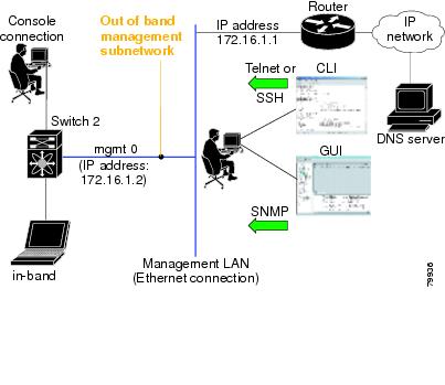
All traffic management is performed through the console connection or the mgmt0 Ethernet interface. (See Figure 12-1.)
Figure 12-1 Management Access to Switches
Management Interface Configuration
The management interface on the switch allows multiple simultaneous Telnet or SNMP sessions. You can remotely configure the switch through the management interface, but first you must configure some IP parameters (IP address, subnet mask) so that the switch is reachable. You can manually configure the management interface from the CLI.
Note
To configure the mgmt0 Ethernet interface, perform this task:
Default Gateway Configuration
The default gateway IP address should be configured along with the IP static routing commands (IP default network, destination prefix, destination mask, and next hop address).
Tip
See the "Initial Setup Routine" section for more information on configuring the IP addresses for all entries in the switch.
Use the IP default-gateway command to configure the IP address for a switch's default gateway and the show ip route command to verify that the IP address for the default gateway is configured.
To configure default gateways, perform this task:
Step 1
switch# config t
Enters configuration mode.
Step 2
switch(config)# ip default-gateway 10.12.11.1
Configures the IP address for the default gateway.
IP Access Control Lists
IP access control lists (IP-ACLs) enhance network security for Cisco MDS 9020 Fabric Switches. IP-ACLs restrict IP-related traffic based on the configured IP filters. A filter contains the rules to match an IP packet, and if the packet matches, the rule also stipulates whether the packet should be permitted or denied.
Each Cisco MDS 9020 Fabric Switch can have a maximum of 64 IP-ACLs, and each IP-ACL can have a maximum of 256 filters.
IP-ACL Configuration Guidelines
When configuring IP-ACLs in a Cisco MDS 9020 Fabric Switch, configure the order of conditions accurately. Because the IP-ACL filters are sequentially applied to the IP flows, only the first match determines the action taken. Subsequent matches are not considered. Be sure to configure the most important condition first. If no conditions match, the software drops the packet.
Filter Contents
An IP filter contains rules for matching an IP packet based on the protocol, address, port, ICMP type, and type of service (TOS).
Protocol Information
The protocol information is required in each filter. It identifies the IP name or number. You can specify the IP in one of two ways:
•
•
Address Information
The address information is required in each filter. It identifies the following details:
•
•
•
•
You can specify the source and source-wildcard or the destination and destination-wildcard in one of two ways:
•
–
–
•
Port Information
The port information is optional. To compare the source and destination ports, use the eq (equal) option, the gt (greater than) option, the lt (less than) option, or the range (range of ports) option. You can specify the port information in one of two ways:
•
•
–
–
ICMP Information
IP packets can be filtered based on the following optional ICMP conditions:
•
•
Table 12-2 displays the value for each ICMP type.
Table 12-2 ICMP Type Value
echo
8
echo-reply
0
destination unreachable
3
traceroute
30
time exceeded
11
1 ICMP redirect packets are always rejected.
TOS Information
IP packets can be filtered based on the following optional TOS conditions:
•
•
IP-ACL -Creation
Traffic coming into the switch is compared with IP-ACL filters based on the order that the filters occur in the switch. New filters are added to the end of the IP-ACL. The switch keeps looking until it has a match. If no matches are found when the switch reaches the end of the filter, the traffic is denied. For this reason, you should have the frequently hit filters at the top of the filter. There is an implied deny for traffic that is not permitted. A single-entry IP-ACL with only one deny entry has the effect of denying all traffic.
To configure an IP-ACL, you must complete the following tasks:
1.
2.
To create an IP-ACL, perform this task:
To define an IP-ACL that permits a specified network, perform this task:
To use the operand and port options, perform this task:
Adding filters to an Existing IP-ACL
After you create an IP-ACL, you place subsequent additions at the end of the IP-ACL. You cannot insert filters in the middle of an IP-ACL. Each configured entry is automatically added to the end of an IP-ACL.
To add entries to an existing IP-ACL, perform this task:
Removing Entries from an Existing IP-ACL
To remove configured entries from an IP-ACL, perform this task:
Reading the IP-ACL Log Dump
Use the log-deny option at the end of a filter condition to log information about packets that match dropped entries. The log output displays the ACL number, permit or deny status, and port information.
For the input ACL, the log displays the raw MAC information. The keyword MAC= does not refer to showing an Ethernet MAC frame with MAC address information. It refers to the Layer 2 MAC-layer information dumped to the log. For the output ACL, the raw Layer 2 information is not logged.
The following example shows an input ACL log dump:
Jul 17 20:38:44 excal-2%KERN-7-SYSTEM_MSG:%IPACL-7-DENY:IN=vsan1 OUT= MAC=10:00:00:05:30:00:47:df:10:00:00:05:30:00:8a:1f:aa:aa:03:00:00:00:08:00:45:00:00:54:00 :00:40:00:40:01:0e:86:0b:0b:0b:0c:0b:0b:0b:02:08:00:ff:9c:01:15:05:00:6f:09:17:3f:80:02:01 :00:08:09:0a:0b:0c:0d:0e:0f:10:11:12:13:14:15:16:17:18:19:1a:1b:1c:1d:1e:1f:20:21:22:23:24 :25:26:27:28:29:2a:2b SRC=11.11.11.12 DST=11.11.11.2 LEN=84 TOS=0x00 PREC=0x00 TTL=64 ID=0 DF PROTO=ICMP TYPE=8 CODE=0 ID=277 SEQ=1280The following example is an output ACL log dump:
Jul 17 20:38:44 excal-2%KERN-7-SYSTEM_MSG:%IPACL-7-DENY:IN= OUT=vsan1 SRC=11.11.11.2 DST=11.11.11.12 LEN=84 TOS=0x00 PREC=0x00 TTL=255 ID=38095 PROTO=ICMP TYPE=0 CODE=0 ID=277 SEQ=1280IP-ACL Interface Application
You can define IP-ACLs without applying them. However, the IP-ACLs will have no effect until they are applied to the switch's interface.
Tip
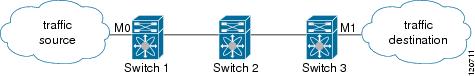
When you are trying to block traffic from source to destination, you can apply an inbound IP-ACL to M0 on Switch 1 instead of an outbound filter to M1 on Switch 3. (See Figure 12-2.)
Figure 12-2 Denying Traffic on the Inbound Interface
The access-group option controls access to an interface. Each interface can only be associated with one access filter per direction. The ingress direction can have a different ACL than the egress direction. The access group becomes active on creation.
Tip
Caution
The terms in, out, source, and destination are used as referenced by the switch.
•
Tip
•
Tip
To create an access group, perform this task:
IP-ACL Configuration Verification
Use the show ip access-list command to view the contents of configured access filters. Each access filter can have several conditions. (See Examples 12-1 and 12-2.)
Example 12-1 Displays Configured IP-ACLs
switch# show ip access-list usageAccess List Name/Number Filters IF Status Creation Time-------------------------------- ------- ---- --------- -------------abc 3 7 active Tue Jun 24 17:51:40 2003x1 3 1 active Tue Jun 24 18:32:25 2003x3 0 1 not-ready Tue Jun 24 18:32:28 2003Example 12-2 Displays a Summary of the Specified IP-ACL
switch# show ip access-list abcip access-list abc permit tcp any any (0 matches)ip access-list abc permit udp any any (0 matches)ip access-list abc permit icmp any any (0 matches)ip access-list abc permit ip 10.1.1.0 0.0.0.255 (2 matches)ip access-list abc permit ip 10.3.70.0 0.0.0.255 (7 matches)IP-ACL Counter Cleanup
Use the clear command to clear the counters for a specified IP-ACL entry.
Note
switch# clear ip access-list counters abcDisplaying IP Interface Information
Use the following show commands to view configured IP interface information. (See Examples 12-3 and 12-4.)
Example 12-3 Displays the Interface
switch# show interface mgmt0mgmt0 is upHardware is FastEthernetInternet address is 10.20.83.122/24Example 12-4 Displays the Connected and Static Route Details
switch# show ip route
Codes: C - connected, S - static
Default gateway is 10.20.83.1C 10.20.83.0/24 is directly connected, mgmt0