Table Of Contents
Power and Cooling Requirements
Line Card Chassis Power System Overview
General Power and Grounding Requirements
DC Power System
DC Power Shelf Wiring
AC Power System
AC Delta and AC Wye Power Shelf Wiring
AC Delta Power Shelf Wiring
AC Wye Power Shelf Wiring
Supplemental Bonding and Grounding
Line Card Chassis Airflow
Power and Cooling Requirements
This chapter describes the power and cooling requirements for the Cisco CRS-1 Carrier Routing System 16-Slot Line Card Chassis. It contains the following sections:
•
Line Card Chassis Power System Overview
•
General Power and Grounding Requirements
•
DC Power System
•
AC Power System
•
AC Delta and AC Wye Power Shelf Wiring
•
Supplemental Bonding and Grounding
•
Line Card Chassis Airflow
Line Card Chassis Power System Overview
The chassis power system provides power to chassis components and is made up of two power shelves that contain power modules. Each power shelf is connected to a separate and independent power source. Input power enters the power shelves and is processed by the power modules before being distributed to the components in the chassis.
Because each power module receives input power from a different power source, the power system provides 2N power redundancy. During normal operation when both power sources are operational, both sets of power shelves and power modules function together to power the chassis. However, if a power sources fails, the other power source provides the other power shelf and power module with enough input power to power the chassis. This 2N power redundancy enables the chassis to operate despite the power failure.
The line card chassis can be either DC or AC powered:
•
-48 VDC or -60 VDC
•
Wye 3-phase, 5-wire connection 200 to 240 VAC (L-N), 3-phase, 3W+N+PE, 25A, 50 to 60 Hz
•
Delta 3-phase, 4-wire connection 200 to 240 VAC (L-L), 3-phase, 3W+PE, 60A, 50 to 60 Hz
Maximum input power requirements for the line card chassis are as follows:
•
A DC-powered chassis requires 13,900 watts (13.9 kW) of DC input power.
•
An AC-powered chassis requires 14,600 watts (14.6 kW) of AC input power.
General Power and Grounding Requirements
This section describes the power and grounding requirements you must consider when planning the site facilities for the line card chassis. In addition, see the "DC Power System" section or the "AC Power System" section for additional power requirements.
Note
A certified electrician should review the information in these sections to ensure that the installation site meets these requirements. For larger system configurations, you may want to consult a facilities electrical expert to understand the load that the routing system may put on the facility power plant.
•
Installation of the fabric card chassis must follow national and local electrical codes:
•
In the United States—United States National Fire Protection Association (NFPA) 70 and United States National Electrical Code (NEC)
•
In Canada—Canadian Electrical Code, part I, CSA C22.1
•
In other countries—International Electrotechnical Commission (IEC) 60364, parts 1 through 7
•
Two separate and independent AC or DC power sources are needed to provide 2N redundancy for system power. Each power source requires its own circuit breaker.
•
Each power source must provide clean power to the site. If necessary, install a power conditioner.
•
The site must provide short-circuit (over-current) protection for devices.
•
Proper grounding is required at the site to ensure that equipment is not damaged by lightning and power surges. In addition:
•
For AC-powered systems, a grounding-type AC power outlet is required.
•
For DC-powered systems, each DC power shelf requires a connection to earth ground.
•
When planning the power for the site, be sure to include the power requirements for any external terminals and test equipment you will use with your system.
Note
Be sure to review the safety warnings in Regulatory Compliance and Safety Information for the Cisco CRS-1 Carrier Routing System before attempting to install the routing system.
DC Power System
To power the line card chassis, the DC power system requires 13,900 watts (13.9 kW) of DC input power. Although the power system provides slightly less power (13.2 kW) to chassis components, the additional input power is required to accommodate the 95% efficiency of the power system.
To provide 2N power redundancy, each DC-powered chassis contains:
•
Two DC power shelves, each powered by a separate and independent power source. Input power connections from the DC power source are made to terminals at the rear of each power shelf.
•
Three DC PEMs in each power shelf (six PEMs in each chassis).
The power shelves and power modules are field replaceable. Each power shelf and power module has its own circuit breaker.
Observe the following guidelines for DC-powered chassis. In addition, be sure to review the requirements in the "General Power and Grounding Requirements" section.
•
Each DC-powered chassis requires 13,900 watts of DC input power.
•
Two separate and independent power sources are required, each providing nominal -48 or -60 VDC, 60-amp service.
•
All power connection wiring should conform to the rules and regulations in the National Electrical Code (NEC) and any local codes. In addition, make sure that the wiring conforms to any internal requirements at the installation site.
•
Each DC power source must comply with the safety extra-low voltage (SELV) requirements in UL 60950-1, CSA-C22.2 No. 60950-1, EN60950-1, AS/NZS 60950, and IEC60950-1.
•
A DC-powered system should be installed in a restricted access area in accordance with the National Electric Code, ANSI/NFPA 70.
•
All components in the area where DC input power is accessible must be properly insulated.
•
A readily accessible two-pole disconnect device must be incorporated in the fixed wiring, unless it is possible to rely on the identification of the power return conductor that is earth-grounded in the DC power system.
•
Each PEM requires two VDC inputs of nominal -48 or -60 VDC, 60-amp service. Because each VDC input consists of two pairs of cable leads, source DC (-) and source DC return (+), you need four wires (two pairs) for each PEM or 12 total wires (six pairs) for each power shelf. In addition, each power shelf requires one grounding wire.
•
All input power cables for the chassis should have the same wire gauge, and cable lengths should match within 10 percent of deviation.
•
For DC input power cables, use the appropriate wire gauge for 60-amp service at nominal DC input voltage (-48 or -60 VDC). We recommend that you use a commensurately rated, high-strand-count copper wire cable. This cable is not available from Cisco Systems; it is available from any commercial vendor. The length of the input power cables depends on the chassis location. The cables must be long enough to reach the chassis from the A and B power bus access points.
Caution 
A certified electrician must select the appropriate DC input power cable based on standard electrical practices, such as derating factors, wiring type, operating temperatures, and so on. The electrician must verify that the cable complies with the National Electrical Code (NEC) and local codes and any guidelines in effect at the installation site. At minimum, DC input power cables must be 6-AWG or heavier and rated for 90°C (194°F) temperature or higher.
Note
Table C-3 and Table C-4 describe DC wire gauges. Note, however, that the information in these tables is provided for planning purposes only. A certified electrician must verify that the selected wire gauge and rating is appropriate for the Cisco CRS-1 installation.
•
An earth ground cable is required for each power shelf. We recommend that you use at least 6-AWG multistrand copper wire, which is available from any commercial cable vendor.
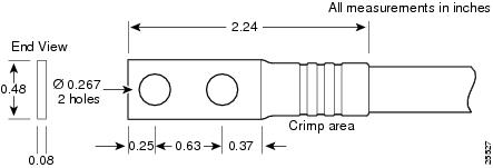
The ground wire cable lug should be dual hole and able to fit over M6 terminal studs at 0.625-inch (15.88-mm) centers (for example, Panduit part number LCD6-14A-L or equivalent). The cable lug is similar to the cable lug for the input power cable (see Figure 3-1).
•
Each DC input power cable must be terminated by a cable lug at the power shelf. The cable lug must be dual hole and able to fit over M6 terminal studs at 0.625-inch (15.88-mm) centers. For example, you could terminate a 6-AWG power cable with a cable lug such as Panduit part number LCD6-14A-L or equivalent (see Figure 3-1).
Figure 3-1 DC Input Power Cable Lug
Note
To avoid hazardous conditions, all components in the area where DC input power is accessible must be properly insulated. Therefore, before installing the DC cable lugs, be sure to insulate the lugs according to the instructions from the manufacturer.
DC Power Shelf Wiring
Each wiring block on the DC power shelf contains two sets of terminals, one positive and one negative, and is covered by a plastic block cover that snaps onto the power shelf and is secured by a screw. You must remove the block cover or rotate it out of the way before you work with the wires. The block covers are slotted in such a way that the wires can exit only one end. If you want the wires pointing in a different direction, remove the block cover, rotate it, and snap it back on.
The color-coding of the DC input power cables depends on the color-coding of the site DC power source. Typically, green or green and yellow indicates that the cable is a ground cable. Because no color-coding standard for the source DC wiring exists, you must ensure that the power cables are connected to the DC-input power shelf terminal studs in the proper positive (+) and negative (-) polarity.
Caution 
DC input power cables must be connected to the power shelf terminal studs in the proper positive (+) and negative (-) polarity. In some cases, the DC cable leads are labeled, which is a relatively safe indication of the polarity. However, you must verify the polarity by measuring the voltage between the DC cable leads. When making the measurement, the positive (+) lead and the negative (-) lead must always match the (+) and (-) labels on the power shelf.
Note
If reverse polarity occurs, the DC power module circuit breaker trips. No damage should occur because of reverse polarity protection, but you should correct the situation immediately.
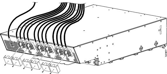
Figure 3-2 shows the DC input power connections at the rear of the power shelf. The ground wire is to the far left on the shelf.
Figure 3-2 DC Power Shelf Input Power Wiring
Table 3-1 DC Input Current and Voltage Information
Nominal input voltage
|
48, 60 VDC (range: -42 to -75 VDC)
|
Input line current
|
50 A maximum at -48 VDC 40 A maximum at -60 VDC
|
Inrush current
|
168 A peak at 75 VDC (maximum for 1 ms)
|
Note
When wiring the power shelf, be sure to attach the ground wire first. When removing the wiring, be sure to remove the ground wire last.
AC Power System
Each AC-powered line card chassis requires 14,600 watts (14.6 kW) of AC input power. Although the AC power system provides slightly less power (13.2 kW) to chassis components, the additional input power is required to accommodate the 90% efficiency of the power system.
Each AC-powered chassis uses two AC power shelves for 2N redundancy. The shelves contain the input power connectors. Each power shelf supports three AC-to-DC rectifiers that are field replaceable. The AC-to-DC rectifiers convert 200 to 240 VAC power to 54.5 VDC used by the line card chassis. Each power shelf and each AC-to-DC rectifier has its own circuit breaker.
Two versions of the AC power shelf are available for AC input power in either the Delta or Wye configuration. Each power shelf has a different Cisco part number to distinguish it from the other. All chassis have two power shelves of the same type; that is, two AC Delta or two AC Wye power shelves.
•
The AC Wye power shelf has a Wye 3-phase, 5-wire connection: 200 to 240 (L-N)/346 to 415 (L-L) VAC, 50 to 60 Hz, 25 A. For redundant operation, two 3-phase Wye branch circuits are required: 40 A (North America) or 32 A (International). One power connection to each power shelf. The 5-wire connection is 3 wire + neutral + protective earthing, or ground wire (3W+N+PE).
•
The AC Delta power shelf has a Delta 3-phase, 4-wire connection: 200 to 240 VAC, 42 A, 50 to 60 Hz. For redundant operation, two 3-phase Delta 60-A branch circuits are required. One power connection to each power shelf. The 4-wire connection is 3 wire + protective earthing, or ground wire (3W+PE).
Cable accessory packages for the AC power shelves contain AC power cables for the power shelves. The power cables, which are 13 feet (4 meters) long, are not shipped preattached to the power shelves.
•
The Wye power cord is rated for 415 VAC, 40 A (North America) or 32 A (International). The power cord has a 5-pin 532P6W plug (3W+N+PE) that plugs into a similarly rated 532R6W power receptacle (see Figure 3-3).
•
The Delta power cord is rated for 250 VAC, 60 A. The power cord has a 4-pin 460P9W plug (3W+PE) that plugs into a 460R9W power receptacle (see Figure 3-4).
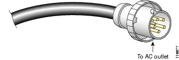
Figure 3-3 AC Wye Power Cord Plug
Figure 3-4 AC Delta Power Cord Plug
For additional power system details, see Cisco CSR-1 Carrier Routing System 16-Slot Line Card Chassis System Description.
AC Delta and AC Wye Power Shelf Wiring
The Cisco CRS-1 line card chassis can be ordered with AC power shelves in either the Delta or Wye configuration. Each type of power shelf has a different Cisco part number to distinguish it from the other. Both types of power shelves require 3-phase, 220-to-240 VAC input power.
•
The AC Delta configuration is typically used in the United States, Japan, and other countries where the phase-to-phase voltage is approximately 208 VAC. The power supplies are wired between the phases (see Figure 3-5) and a neutral is not required.
•
The AC Wye configuration is typically used in Europe and countries where each phase-to-neutral voltage is approximately 220 VAC. The power supplies are wired between each phase and neutral (see Figure 3-6).
AC Delta Power Shelf Wiring
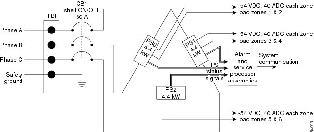
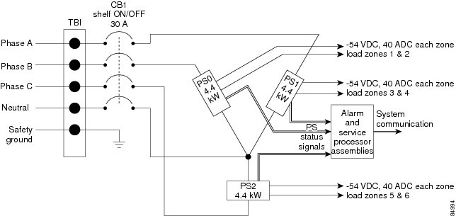
Figure 3-5 is a sample of how AC Delta power is wired to the power shelf. As shown, AC Delta has 4 wires (three phases and a safety ground) wired into a terminal board (TB1) on the power shelf. The input-AC power is routed through a circuit breaker (CB1) to the three 4.4-kW AC rectifiers (PS0, PS1, and PS2), where it is converted into DC power (nominal 54.5 VDC, 37 ADC) and routed to the six load zones of the chassis. The load zones distribute power to the various components in the chassis through the backplane. Power supply status signals are also routed to an alarm and service processor for system communication.
Figure 3-5 AC Delta Power Shelf Wiring
AC Wye Power Shelf Wiring
Figure 3-6 is a sample of how AC Wye power is wired to the power shelf. As shown, the AC Wye configuration has 5 wires (three phases, neutral, and a safety ground) wired into a terminal board (TB1) on the power shelf. The input-AC power is routed through a circuit breaker (CB1) to the three 4.4-kW AC rectifiers (PS1, PS2, and PS3), where it is converted into DC power (nominal 54.5 VDC,
37 ADC) and routed to the six load zones of the chassis. The load zones distribute power to the various components in the chassis through the backplane. Power supply status signals are also routed to an alarm and service processor for system communication.
Figure 3-6 AC Wye Power Shelf Wiring
Supplemental Bonding and Grounding
The line card chassis has a safety earth ground connection as part of the power cabling to the power shelves. The chassis also has a supplemental bonding and grounding point (two threaded ground inserts) that you can use to connect the chassis to the central office ground system or interior equipment grounding system. This grounding point is sometimes referred to as network equipment building system (NEBS) bonding and grounding studs.
The threaded ground inserts are located on top of the chassis rear panel on the back of the chassis to the left of the lower power shelf (see Figure 3-7).
Figure 3-7 NEBS Bonding and Grounding Points
1
|
NEBS supplemental bonding and grounding points
|
The grounding points are obscured by a cover plate. When the cover plate is removed, you can easily see the labels indicating the location of the grounding points. Two grounding points are provided; although you may use both if you wish, only one is needed for NEBS grounding purposes.
Note
The NEBS bonding and grounding points are intended to satisfy the Telcordia NEBS requirements for supplemental bonding and grounding connections. If you are not installing the router in an NEBS environment, you can skip these guidelines and rely on the safety earth ground connection.
To connect the chassis to a supplemental ground connection, you must have the following:
•
Grounding lug that has two M6 bolt holes with 0.625 to 0.75 inches (15.86 to 19.05 mm) of spacing between them and a wire receptacle large enough to accept a 6-AWG or larger multistrand copper wire. The lug is similar to the type used for the DC input power cables (see Figure 3-1). The lug is not available from Cisco Systems; it is available from electrical-connector vendors, such as Panduit.
•
Two M6 or equivalent hex-head bolts and locking washers (nickel-plated brass is ideal). These bolts, locking washers, and nuts are not available from Cisco Systems; they are available from any commercial hardware vendor.
•
Grounding wire. Although we recommend at least 6-AWG multistrand copper wire, the actual wire diameter and length depend on your router location and site environment. This wire is not available from Cisco Systems; it is available from any commercial cable vendor.
Line Card Chassis Airflow
The airflow through the line card chassis is controlled by a push-pull configuration. As shown in the following figure, ambient air flows in at the bottom front of the line card chassis and up through the card cages until it exhausts at the top rear. The bottom fan tray pulls ambient air in from the bottom front of the chassis; the top fan tray pushes warm air out the back of the chassis. The power modules in the power shelves have their own self-contained cooling fans.
A replaceable air filter is positioned above the lower fan tray. How often the air filter should be replaced depends on the facility environment. In a dirty environment, or when you start getting frequent temperature alarms, you should always check the intake grills for debris, and then check the air filter to see if it needs replacement.
Before removing the air filter for replacement, you should have a spare filter on hand; then, when you remove the dirty filter, install the spare filter in the chassis.
Figure 3-8 Airflow Through Line Card Chassis
The line card chassis has a maximum airflow of 2050 cubic feet per minute.
Note
You should consider ordering and installing the rear grille on the chassis (CRS-16-LCC-R-GRL). The grille directs the flow of the air exhaust upward and away from the aisle.