Feedback
Table Of Contents
Problem Solving with Subsystems
Troubleshooting the Power Subsystems
Troubleshooting the Cooling Subsystems
Troubleshooting the Processor Subsystems
Troubleshooting the Feature Cards
Troubleshooting Network Interfaces
Hardware Troubleshooting
Your Cisco AS5850 was thoroughly tested before leaving the factory. If you encounter problems initializing system startup, use the information in this chapter to help isolate the cause.
This chapter contains the following sections:
•
Problem Solving with Subsystems
•
•
•
•
The procedures in this chapter assume that you are troubleshooting the initial hardware configuration and system startup. If you have removed or replaced components or changed any default settings, the recommendations in this chapter might not apply. Review the safety warnings listed in the publication Cisco AS5850 Universal Gateway Regulatory Compliance and Safety Information before using the troubleshooting procedures in this chapter.
If you are unable to resolve the problem, contact a customer service representative (see the "Obtaining Technical Assistance" section on page xiv) for assistance and further instructions. Provide the representative with the following information:
•
•
•
•
•
•
Problem Solving with Subsystems
The key to problem solving is isolating the problem to a specific subsystem. The first step in solving startup problems is to compare what the system is doing to what it should be doing. Try to isolate the problem to one of the following three subsystems:
•
•
•
Start by checking the power components. Power components include the following:
•
•
•
•
•
Next, check the cooling components. Fans should be operating whenever system power is on. Cooling components include the following:
•
•
Last, check the server processor cards. Most processor cards contain LEDs that indicate the status of the card. Observing these LEDs can help you isolate the problem to a particular card. (See "Powering On the Cisco AS5850 and Observing Initial Startup Conditions," for LED descriptions and troubleshooting tips.) The system memory and management functions reside on the route switch controller card.
The following sections will help you isolate a problem within one of these subsystems and direct you to the appropriate troubleshooting section.
Identifying Startup Problems
Hardware startup problems are commonly traced to cabling problems or incorrectly installed power supplies or cards. In rare cases, problems are caused by part failures.
When you start up a Cisco AS5850 for the first time, you should observe the startup sequence, described in the following sections. This chapter describes the normal startup sequence for the universal gateway and the steps to take if the system does not perform that sequence as expected.
In most cases, LEDs indicate system states in the startup sequence. By checking these LEDs, you can determine when and where the system failed. Use the following descriptions to isolate the problem to a subsystem, then proceed to the appropriate sections to try to resolve the problem.
Note
When you first power on the Cisco AS5850, the following should occur:
•
If the green power LEDs do not come on, proceed to the section "Troubleshooting the Power Subsystem."
•
If the fans do not operate, proceed to the section "Troubleshooting the Cooling Subsystems."
•
–
–
–
–
If the processor component LEDs do not come on as described, proceed to the section "Troubleshooting the Processor Subsystems."
Troubleshooting the Power Subsystems
The Cisco AS5850 is designed to minimize problems in the power subsystem. The power subsystem includes the PEMFs and the 2400 W AC-input power shelf (if used).
The Cisco AS5850 comes with two DC power entry modules, which allow you to replace power supplies while the system is operating. However, if you are using an AC-configured system and you discover a faulty PEMF, you must power off the system before performing a replacement.
Caution
The failure of a single PEMF or AC power module, if used, will not stop the universal gateway from operating; however, to maintain power redundancy, both DC PEMFs and all three AC power modules must be receiving power.
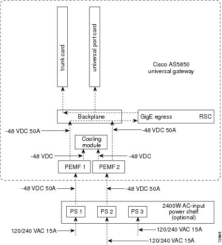
Figure 5-1 shows the flow of power for either AC-input or DC-input systems. Understanding this flow can aid in diagnosing power flow problems.
Figure 5-1 Power Distribution
Check the following points in the order given to help isolate a problem with the power subsystem:
•
–
–
–
If a power module FAULT LED comes on, the power shelf has detected an internal fault; the power module is defective. You need to replace the power module.
•
–
–
If the MISWIRE LED is off, the DC-input connection is wired correctly.
If the MISWIRE LED is on, the two DC conductors entering the PEMF terminal block are reversed. Power off the power at your power source and reverse the connections.
–
•
–
–
•
–
–
•
–
–
Troubleshooting the Cooling Subsystems
The Cisco AS5850 is designed to minimize problems in the cooling subsystem. The Cisco AS5850 can operate in temperatures of up to 120°F (50°C) for a maximum of 72 hours. The universal gateway also contains redundant fans in the cooling module, which allow the system to continue operating despite a single fan failure. The cooling module can be removed and replaced while the system is operating, provided that the procedure does not exceed 1 minute.
Check the following to help isolate a problem with the cooling system:
•
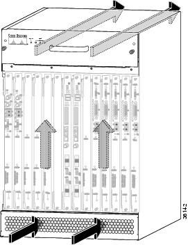
To properly cool the universal gateway, cool air needs to enter through the intake vent, flow up and past the cards, and get pushed out of the server exhaust by the fans in the cooling module (see Figure 5-2). If a card cage slot is left open, air can enter into the chassis through the card cage rather than the intake vent, upsetting the intended air flow. This prevents cards in the card cage from being cooled properly.
Figure 5-2 Airflow
•
To determine whether the fans are operating, listen for them. In noisy environments, place your hand under the exhaust vents on the back of the cooling module to feel for air being forced out the vents. If no air is coming out, there is a problem with the fans or there is a problem with the power to the cooling module.
If you determine that the power supply is functioning normally but a fan is faulty, you can replace the cooling module without powering off the universal gateway. Refer to the cooling module removal instructions in "Preparing for Installation," and the reinsertion instructions in "Installing the Cisco AS5850." For problems with the system power, refer to the section "Troubleshooting the Power Subsystem" in this chapter.
•
If no, verify that the cooling module is fully installed in the server, the connector is firmly connected to the PEMF, and the captive screws are tightened adequately.
•
There are three fault LEDs, one for each bank of fans in the cooling module. If one of these LEDs is on, the newly installed cooling module might be faulty or the Mbus and power connector might be damaged. Shut off system power, remove the cooling module, and check the connectors. If the connectors are in good condition, reinstall the cooling module in the chassis and power ON the system. If the fault LED is still on, assume that the cooling module is faulty. Install another cooling module and return the faulty cooling module to the factory.
•
Queued messages:%ENVM-1-SHUTDOWN: Environmental Monitor initiated shutdownIf an environmental shutdown results from an out-of-tolerance power condition, the POWER LED remains off and the system shuts down. (Refer to the section "Troubleshooting the Power Subsystems" in this chapter.) Although an overtemperature condition is unlikely at initial startup, ensure that heated exhaust air from other equipment is not entering the server's inlet vent and that there is sufficient clearance around the sides of the chassis to allow cooling air to flow. Refer to the "Preventive Site Configuration: Maintaining Normal Operation" section for preventive site configurations.
The previous error message could also indicate a faulty component or temperature sensor. Before the system shuts down, find out exactly which component is experiencing temperature or voltage problems. Use the show environment table command to display the internal power and temperature thresholds, and compare the thresholds with current conditions listed in the output from the show environment command.
Troubleshooting the Processor Subsystems
The processor subsystem consists of the route switch controller card, port cards, and trunk cards in the Cisco AS5850. The following sections contain specific troubleshooting information for each of these components.
The RSC is a required system component. The system cannot operate unless at least one RSC is installed properly; however, the system can operate without any feature cards installed, as long as none are in partial contact with the backplane pins. A server card that is partially connected to the backplane may cause the universal gateway to crash or to hang. Therefore, first ensure that the RSC is installed properly and that the system software has initialized successfully. Then, if necessary, you can troubleshoot individual feature cards.
Troubleshooting the RSC
The following sections describe troubleshooting procedures for the RSC.
These procedures assume that the RSC is in the original factory configuration and that you have not made changes to your configuration file.
If the RSC LEDs do not come on as expected (refer to the section "Identifying Startup Problems" in this chapter), check the following items to help isolate the problem:
•
–
–
•
–
–
To inspect the backplane pins, first power off the system to avoid hazards caused by high voltages present on the backplane connectors. Next, remove cards in neighboring slots to allow an unimpeded view of the backplane connectors. Then, using a flashlight, verify that the backplane connectors are in good condition. If you discover bent pins, you need a new backplane. Contact your service representative to order a new backplane.
•
Router> enableenter password passwordRouter# show diag type {shelf | slot}Ctrl-ZTroubleshooting the Feature Cards
Troubleshooting information for T1, E1, CT3, or STM1 trunk cards or port cards is available in the Cisco AS5850 Universal Gateway Card Guide that shipped with your system.
Troubleshooting Network Interfaces
For information about isolating problems with the network connections to your universal gateway, refer to the publication Internetwork Troubleshooting Guide, which is available on the Cisco Documentation CD-ROM that shipped with your Cisco AS5850. For more information, see the "Related Documentation" section on page xii.