Feedback
Table Of Contents
Powering On the Cisco AS5850 and Observing Initial Startup Conditions
Observing Universal Gateway LEDs
Observing Power-Entry Module LEDs
Observing Route Switch Controller Card LEDs
Viewing Your System Configuration
Powering On the Cisco AS5850 and Observing Initial Startup Conditions
This chapter explains how to power on the Cisco AS5850 and confirm normal system startup LED readings, and then confirm that the proper software is running.
This chapter contains the following sections:
•
Observing Universal Gateway LEDs
•
Powering On the Cisco AS5850
After you have installed your universal gateway and connected the cables, you are ready to start up the system by powering on the following components:
•
•
Before you power on the Cisco AS5850, you might want to prepare a terminal connection to view the software startup sequence. See the "Connecting to the RSC Console and Auxiliary Ports" section for details on setting up a terminal connection. You should also confirm the LED indications as shown in the "Observing Universal Gateway LEDs" section.
To power on the system, follow these steps:
Step 1
Step 2
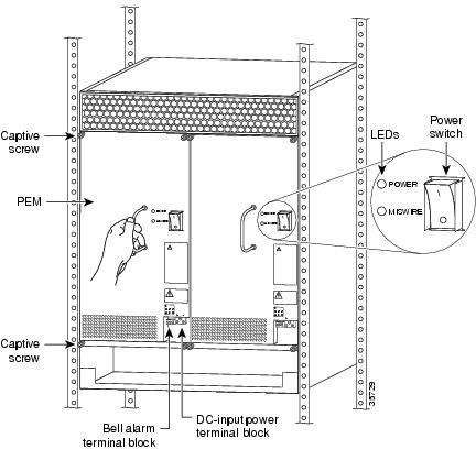
Figure 4-1 AC-Input Power Shelf—Front View
Step 3
Figure 4-2 PEMF Power Switches
Step 4
During the boot process, the LEDs on most of the port adapters in the universal gateway cards and route switch controller cards come on and go off in irregular sequence while the system is running initial self-diagnostic tests. On the RSC, the PWR LED comes on immediately.
For a description of normal server LED states, proceed to the following section "Observing Universal Gateway LEDs."
Observing Universal Gateway LEDs
This section describes the normal LED states for the following components:
•
•
•
Nominal LED Readings
Table 4-1 provides a quick reference for nominal LED readings for Cisco AS5850 core components. If LED readings vary from those listed, refer to the relevant sections for more details. If everything seems to be normal, complete the startup check with a console connection as described in the "Viewing Your System Configuration" section.
Server Card LEDs
LEDs for the individual CE1/CT3 trunk cards and 324 universal port cards are described in the Cisco AS5850 Universal Gateway Card Guide. Nominal LED readings are briefly listed in Table 4-2.
Observing Power-Entry Module LEDs
The PEMFs contain the following LEDs on the front panel—POWER and MISWIRE.
•
•
If either of these LEDs functions abnormally, proceed to Chapter 5, "Hardware Troubleshooting."
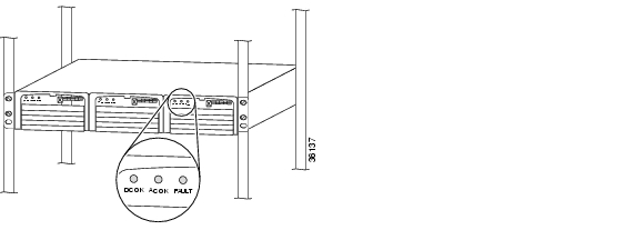
Figure 4-3 shows the location of the PEMF LEDs.
Figure 4-3 PEMF Front Panel LEDs
Observing Route Switch Controller Card LEDs
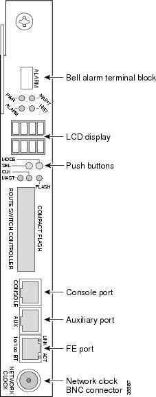
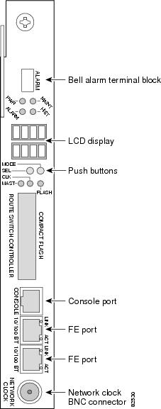
The route switch controller card front panel contains several LEDs. Figure 4-4 and Figure 4-5 show the route switch controller card front panel LEDs, and Table 4-3 describes the LED functions.
If the route switch controller card LEDs function abnormally, proceed to Chapter 5, "Hardware Troubleshooting."
Figure 4-4 RSC Front Panel LEDs
Figure 4-5 ERSC Front Panel LEDs
Note
1 A major alarm condition includes RSC failure, backplane failure, fan failure, power module failure, server card failure, or conditional environmental thresholds.
2 A minor alarm condition includes modem SIMM failure, HDLC controller failure, trunk line failure, or conditional environmental thresholds.
Cooling Module LEDs
Four LEDs—Power and Fault for fan banks 1 through 3—are mounted on the cooling module front panel, and function as described in Table 4-4.
If you detect a problem with the cooling module LEDs, proceed to Chapter 5, "Hardware Troubleshooting."
Viewing Your System Configuration
When you start up your universal gateway for the first time, the console displays the Cisco IOS software information that is loaded on your system, if you have connected a terminal as described in the "Connecting to the RSC Console and Auxiliary Ports" section. From this startup software banner (see the following example), you can identify the Cisco IOS software release version, other platform images that support system component functionality, and installed internal hardware components.
System Bootstrap, Version 12.2(2)T, RELEASE SOFTWARE (fc1)Copyright (c) 2000 by cisco Systems, Inc.5850-rsc platform with 262144 Kbytes of main memoryRestricted Rights LegendUse, duplication, or disclosure by the Government issubject to restrictions as set forth in subparagraph(c) of the Commercial Computer Software - RestrictedRights clause at FAR sec. 52.227-19 and subparagraph(c) (1) (ii) of the Rights in Technical Data and ComputerSoftware clause at DFARS sec. 252.227-7013.cisco Systems, Inc.170 West Tasman DriveSan Jose, California 95134-1706Cisco Internetwork Operating System SoftwareIOS (tm) 5850 Software (C5850-p9-mz), Released Version 12.2(2)XBCopyright (c) 1986-2001 by cisco Systems, Inc.Compiled Tue 28-Aug-01 16:20 by rajeshkImage text-base: 0x60008960, data-base: 0x6160E000cisco c5850 (R7K) processor (revision 0.12) with 196608K/65536K bytes of memory.R7000 CPU at 259Mhz, Implementation 39, Rev 2.1, 256KB L2, 2048KB L3 CacheLast reset from Mbus resetChannelized E1, Version 1.0.X.25 software, Version 3.0.0.Bridging software.SuperLAT software (copyright 1990 by Meridian Technology Corp).Primary Rate ISDN software, Version 1.1.1 FastEthernet/IEEE 802.3 interface(s)2 Gigabit Ethernet/IEEE 802.3 interface(s)1404 terminal line(s)24 Channelized E1/PRI port(s)24 Channelized T1/PRI port(s)2 Channelized T3 port(s)507K bytes of non-volatile configuration memory.32768K bytes of Compact Flash card at slot 0 (Sector size 128K).16384K bytes of Flash internal SIMM (Sector size 256K).Your Cisco AS5850 should be running the following software:
•
•
•
If you find you that have a different Cisco IOS software release, reload the correct software version. If you need to reload the software, refer to the Cisco AS5850 Operations, Administration, Maintenance, and Provisioning Guide, available online at: http://www.cisco.com/univercd/cc/td/doc/product/access/acs_serv/as5850/sw_conf/5850oamp/ index.htm
If you established a terminal connection after initial startup, you can verify that the correct software is loaded by issuing the following commands at the terminal:
Step 1
Router# show verCisco Internetwork Operating System SoftwareIOS (tm) 5850 Software (C5850-P6-M), Version 12.x(xxxxxxxx:xxxxxx) [ssangiah-121_5_xv_build 248]Copyright (c) 1986-2000 by cisco Systems, Inc.Compiled Thu 07-Dec-00 05:31 byImage text-base:0x60008960, data-base:0x61114000ROM:System Bootstrap, Version 12.0(20001106:230712) [gclendon-v121_5_xv_throttle 101], DEVELOPMENT SOFTWAREROM:5850 Software (C5850-BOOT-M), Version 12.1(xxxxxxxx:xxxxxx) [ssangiah-121_5_xv_build 251]5850 uptime is 1 day, 2 hours, 52 minutesSystem returned to ROM by reload at 00:14:27 UTC Sat Jan 1 2000System image file is "disk0:c5850-p6-mz.Dec7"cisco c5850 (R7K) processor (revision 0.12) with 491520K/32768K bytes of memory.R7000 CPU at 262Mhz, Implementation 39, Rev 2.1, 256KB L2, 2048KB L3 CacheLast reset from Mbus resetX.25 software, Version 3.0.0.Bridging software.SuperLAT software (copyright 1990 by Meridian Technology Corp).Primary Rate ISDN software, Version 1.1.1 FastEthernet/IEEE 802.3 interface(s)2 Gigabit Ethernet/IEEE 802.3 interface(s)48 Serial network interface(s)540 terminal line(s)2 Channelized T1/PRI port(s)1 Channelized T3 port(s)1 Dial Shelf Interconnect(DSI) FE interface(s)507K bytes of non-volatile configuration memory.32768K bytes of Compact Flash card at slot 0 (Sector size 128K).16384K bytes of Flash internal SIMM (Sector size 256K).Configuration register is 0x2Step 2
Router# show chassisSystem is in split shelf mode, connected to RSC in slot 6.Slots owned:0 1 2 3 4 5Slots owned by other:8 9 10 11 12 13Slot Board CPU DRAM I/O Memory State ElapsedType Util Total (free) Total (free) Time2 CT3_UP216 0%/0% 94444736( 81%) 33554432( 49%) Up 00:02:254 Multi(324) 20%/19% 94444736( 80%) 33554432( 53%) Up 00:02:38System set for auto bootFor other software-related issues, refer to the Cisco AS5850 Universal Gateway Commissioning Guidelines that shipped with your system, or the Cisco AS5850 Universal Gateway Operation, Administration, Maintenance, and Provisioning Guide. These documents are available on Cisco.com (http://www.cisco.com), by selecting:
Products and Services > Universal Gateways > Cisco AS5800 Universal Gateways
Where to Go Next
Your universal gateway is now installed, and all components are operative. When you power on the universal gateway for the first time, messages appear on your console screen. When the initialization process is complete, the console screen displays a script and system banner. At this point, you can begin to configure the software. Refer to the Cisco AS5850 Universal Gateway Commissioning Guidelines that shipped with your system, or the Cisco AS5850 Universal Gateway Operation, Administration, Maintenance, and Provisioning Guide. These documents are available on Cisco.com (http://www.cisco.com), by selecting:
Products and Services > Universal Gateways > Cisco AS5800 Universal Gateways