
Table Of Contents
Cisco AS5850 Packaging Replacement Instructions
Preparing to Repackage the Cisco AS5850 Universal Gateway
Repackaging the Cisco AS5850 Universal Gateway
Cisco AS5850 Packaging Replacement Instructions
This appendix provides packaging material information for the Cisco AS5850 universal gateway, and explains how to prepare the universal gateway for repackaging and how to package the universal gateway for shipping. This appendix assumes that you are returning your entire Cisco AS5850. If you are returning an empty chassis, use these instructions as applicable.
The Cisco AS5850 is a large, heavy chassis; it measures 19-in. (48.3 cm) wide, 21-in. (53.3 cm) deep, and 56-in. (142.2 cm) high. A fully configured universal gateway weighs approximately 221 lb (100.2 kg). In order to ship the chassis safely, a packaging kit has been engineered to prevent shock damage. This is the same packaging kit originally used to ship the universal gateway. If your original system packaging is damaged or was discarded, you must order a replacement packaging kit.
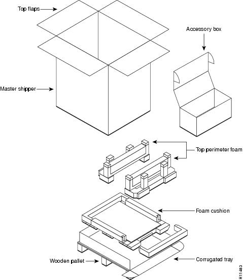
Figure C-1 shows the universal gateway packaging detail.
Figure C-1 Cisco AS5850 Packaging Detail
Required Tools and Parts
You need the following tools and parts to remove and repackage the Cisco AS5850 components:
•
Your own ESD-preventive wrist strap
•
Cable ties (recommended, but not essential)
•
An antistatic mat
•
No. 2 Phillips screwdriver
•
1/4-in. flat-blade screwdriver
•
Standard strapping tool and strap or banding material
•
Cisco AS5850 repackaging kit (PKG-AS5850=), which includes:
–
Wooden pallet and base tray assembly (corrugated tray, foam cushions, corrugated chassis platform)
–
Plastic bag
–
Top perimeter foam
–
Accessory box
–
Master shipper
Powering Off the Cisco AS5850
You must power off the Cisco AS5850 before attempting to dismantle the universal gateway for repackaging.
Powering off the universal gateway involves the following components:
•
PEMF
•
AC-input power shelf, if applicable
To power off the Cisco AS5850, follow these steps:
Warning
Before working on equipment that is connected to power lines, remove jewelry (including rings, necklaces, and watches). Metal objects will heat up when connected to power and ground and can cause serious burns or weld the metal object to the terminals. To see translations of the warnings that appear in this publication, refer to the Regulatory Compliance and Safety Information document that accompanied this device.
Step 1
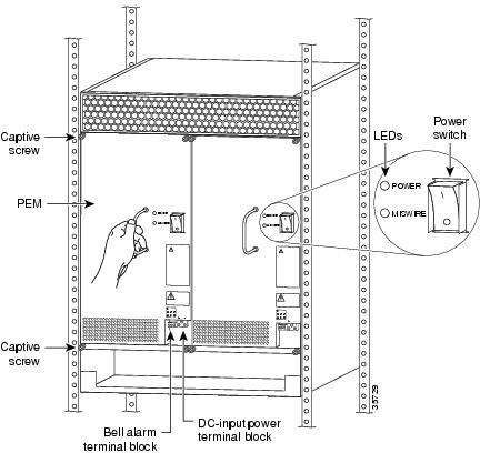
Power off (O) the power switches located on each universal gateway PEMF front panel. (See Figure C-2.)
Figure C-2 Power Switches on the PEMFs
Step 2
If you are using the optional AC-input power shelf, unplug the AC input power cables
Step 3
Power OFF the central office main circuit breaker.
CautionIf you are using the optional AC-input power shelf, you must power off all three AC-input power supplies before you disconnect the DC cables from the DC terminal blocks.
Step 4
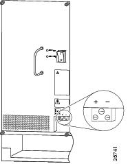
Loosen the screws in the DC-input power terminal blocks and the alarm terminal blocks using a 1/4-inch flat-blade screwdriver, and disconnect power cables and alarm cables to the universal gateway PEMFs. Figure C-3 shows the location of the terminal blocks.
Figure C-3 PEMF DC Terminal Block
Step 5
Disconnect the DC power cables from your DC power source.
The last two steps refer to the optional AC-input power shelf. If you are using a DC power source, you can skip Step 6 and Step 7 and proceed to the section "Preparing to Repackage the Cisco AS5850 Universal Gateway."
Step 6
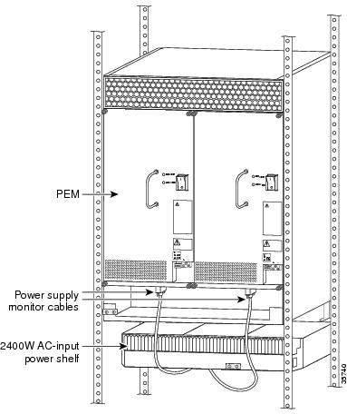
Disconnect the monitor cable DB-9 connector from the base of the PEMF. (See Figure C-4.)
Figure C-4 PEMF Monitor Cable DB-9 Connector
Step 7
Disconnect power cables to the optional AC-input power shelf. (See Figure C-4.)
Step 8
Disconnect incoming STM1 optical cable or CT1, E1 or CT3 trunk line cables and secure them out of the way using cable ties, if necessary. On the RSC, disconnect the universal gateway interconnect cable and the BNC connection if applicable.
This completes the power-off sequence. Proceed to the following section, "Preparing to Repackage the Cisco AS5850 Universal Gateway."
Preparing to Repackage the Cisco AS5850 Universal Gateway
The Cisco AS5850 is equipped with a blower assembly, server cards (trunk and modem cards) and route switch controller cards configured in the chassis. Fully loaded, the universal gateway weighs 221 lb (100.2 kg).
Before removing the Cisco AS5850 from the rack, Cisco recommends that you remove the server cards, controller cards, and the blower assembly from the universal gateway to decrease the chassis weight (see the "Removing the Cooling Module" section on page 3-3 and the "Removing Trunk and Port or RSC Cards" section on page 3-5). Then reinstall the components (see the "Replacing the Universal Gateway Components" section on page 3-16) after the universal gateway is seated on the shipping pallet/base tray assembly.
Repackaging the Cisco AS5850 Universal Gateway
To repackage the Cisco AS5850, follow these steps:
Step 1
Lay the opened plastic bag, with sides rolled down, on the pallet/base tray assembly. (See Figure C-1.)
Step 2
Remove the screws securing the rear mounting brackets on the chassis to the rear rack posts. Next, remove the rear brackets from the universal gateway chassis.
CautionIf the universal gateway is suspended in the rack, install the two support brackets that were included in your original rack-mount kit under the chassis to prevent it from falling while you are removing the rack-mount screws and brackets.
Step 3
Remove the screws securing the front of the chassis to the rack.
Step 4
Lift and slide the chassis out of the rack.
Warning
Two people are required to lift the chassis. Grasp the chassis underneath the lower edge and lift with both hands. To prevent injury, keep your back straight and lift with your legs, not your back. To prevent damage to the chassis and components, never attempt to lift the chassis with the handles on the power supplies or on the interface processors, or by the plastic panels on the front of the chassis. These handles were not designed to support the weight of the chassis. To see translations of the warnings that appear in this publication, refer to the Regulatory Compliance and Safety Information document that accompanied this device.
Step 5
Seat the universal gateway on the pallet/base tray assembly, and remove the front rack-mount brackets from the chassis sides, if applicable.
Step 6
Place all accessories (including power cords, cables, documentation, and mounting hardware) in the accessories box and tape the box closed.
Step 7
Replace the blower assembly, server cards, and controller cards you removed into the universal gateway chassis.
Step 8
Pull the sides of the plastic bag up over the chassis and seal the bag.
Step 9
Position the foam around the top chassis perimeter.
Step 10
Place the accessories box on top of the universal gateway chassis.
Step 11
Slide the master shipper over the top of the chassis and base tray; close the top flaps and seal with tape. (See Figure C-1.)
Step 12
Secure the container to the pallet and base tray using a standard strapping tool and banding.
The Cisco AS5850 universal gateway is now packaged and ready to be transported. Use a forklift or pallet jack to move the universal gateway container.

 Feedback


