Table Of Contents
Cisco AS5850 Specifications
System Specifications
Backplane Specifications
Cooling Module Specifications
RSC Specifications
Gigabit Ethernet Specifications
DC PEMF Specifications
AC Power Supply Specifications
Power Shelf Cables
Cisco AS5850 Specifications
System Specifications
Table A-1 describes the Cisco AS5850 specifications.
Table A-1 Cisco AS5850 Specifications
Description
|
Specification
|
Dimensions (H x W x D)
|
28.0 x 17.4 x 23.6 in. (71.1 x 44.2 x 59.9 cm)
|
Component Weights
|
|
With PEMF, cooling module, and 14 cards
|
221 lb (100.2 kg)
|
Without PEMF, cooling module, and cards installed
|
55 lb (24.94 kg)
|
Backplane
|
2.5 lb (1.1 kg)
|
Trunk/port card
|
8.5 lb each (3.8 kg)
|
Trunk card
|
8.5 lb each (3.8 kg)
|
Port card
|
8.5 lb each (3.8 kg)
|
RSC card
|
9 lb each (4.0 kg)
|
Cooling module
|
23 lb (10.4 kg)
|
DC power-entry module
|
11.5 lb each (5.2 kg)
|
AC-input power shelf (empty)
|
7 lb (3.2 kg)
|
AC-input power module
|
7 lb each (3.2 kg)
|
Environmental Requirements
|
|
Operational temperature
Maximum operating temperature
Acceptable temperature rise
Maximum heat generated
Maximum acoustic noise level
|
23 to 104°F (-5 to 40°C)
23 to 120°F (-5 to 50°C) (not more than 96 hours)
30°C per hour
8,000 BTU
65 dB
|
Backplane
|
14 slots
|
Power
|
Typical: 2000, Maximum: 2400
|
Frequency
|
50/60 Hz
|
Heat dissipation
|
2,000W (6820 BTU per hour)
|
AC-input voltages and frequency
|
85 to 264VAC
47 to 63 Hz
|
AC voltage and current
|
120 VAC at 16A maximum1 wide input with power factor correction (PFC)
240 VAC at 7A maximum
|
AC cable
|
12 American Wire Gauge (AWG), with three leads, an IEC-320 receptacle on the power supply end, and a US standard 3-prong 120V plug on the power source end
|
DC-input voltage
|
-48 VDC to -60 VDC
|
DC-input cable
|
6 AWG for North American environments
10 mm2 wire for international environments when connecting directly to a DC power source
|
Relative Humidity
|
|
Operating
Nonoperating
|
10 to 90%, noncondensing
10 to 95%, noncondensing
|
Factory-Installed Memory
|
|
RSC card
|
512-MB SDRAM
|
ERSC card
|
1-Gb DDR SDRAM
|
T3 trunk card
|
128-MB DRAM
|
T1/E1 trunk card
|
128-MB DRAM
|
SDH/STM-1 trunk card
|
128-MB DRAM
|
324 universal port card
|
128-MB DRAM
|
Regulatory Compliance
|
|
Agency approvals
|
Safety: UL 1950, CSA 22.2 No. 950, EN60950, ACA TS001, AS/NZS 3260, IEC 60950
Emissions: CFR 47 Part 15 Class A (FCC), CISPR22 Class B, EN55022 Class B, AS/NRZ 3548 Class B, ICES003, VCCI Class B, CNS13438 Class A
Immunity: IEC 1000-3-2, IEC 1000-3-3, IEC-1000-4-2, IEC-1000-4-3, IEC-1000-4-4, IEC-1000-4-5, IEC-1000-4-6, IEC-1000-4-11, EN50082-1, EN50082-2
For additional compliance information refer to the Regulatory Compliance and Safety Information documents that shipped with your system.
|
Backplane Specifications
Table A-2 lists the backplane DC power specifications.
Table A-2 Backplane—DC Power Requirements
Description
|
Specification
|
Input Voltage
|
Minimum
Minimum/Nominal
Nominal
Maximum/Nominal
Maximum
|
-20 (10 ms)
-38 VDC
-48 VDC
-72 VDC
-75 (IS)
|
Output Voltage
|
Maximum
Nominal
Minimum
|
-38 VDC
-51 VDC
-75 VDC
|
Current
|
Nominal
Minimum (SS)
Maximum (SS)
Peak (2 sec)
|
42A
3A
60A
80A
|
Table A-3 lists the backplane environmental specifications.
Table A-3 Backplane—Environmental Specifications
Description
|
Specification
|
Dimensions (H x W)
|
12.75 x 16.75 in. (32.4 x 42.5 cm)
|
Cooling
|
Maximum inlet air temperature is 131°F (55°C)
|
Temperature
|
Operating
Nonoperating
|
23 to 131°F (-5 to 55°C)
-13 to 158°F (-25 to +70°C)
|
Humidity
|
Operating
Nonoperating
|
10 to 90%, noncondensing
10 to 95%, noncondensing
|
Altitude
|
Operating
Nonoperating
|
9,843 ft (3,000 m) at 104°F (40°C)
15,000 ft (4,570 m) over allowable temperature range
|
Thermal shock
|
Operating
Nonoperating
|
23 to 113°F (-5 to 45°C at 0.5°C) per minute
-13 to 158°F (-25 to 70°C) with changeover time between 2 and 3 min
|
Vibration
|
Operating
Nonoperating
|
1.12 g from 3 to 500 Hz
2 g from 3 to 500 Hz
|
Ripple and noise
|
200 mV
|
Noise
|
Battery feed noise
Voice frequency noise
Radio frequency noise
|
3 KHz band between 10 KHz and 20 MHz
70 dBrnC
500 mV RMS
|
|
Long-term voltage drift
|
± -0.5%
|
Cooling Module Specifications
Table A-4 lists cooling module DC power requirements.
Table A-4 Cooling Module—DC Power Requirements
Power
|
Specification
|
Voltage to backplane
|
Maximum
Nominal
Minimum
|
-72 VDC
-48 VDC
-38 VDC
|
Current
|
Minimum (SS)
Nominal (SS)
Maximum (SS)
Peak (2 sec)
|
3.0A
42.0A
54.0A
60.0A
|
Table A-5 lists the cooling module environmental specifications, which are designed to meet NEC, NEBS, and ETSI requirements.
Table A-5 Cooling Module—Environmental Specifications
Specification
|
Description
|
Cooling
|
Maximum inlet air temperature is 131° F (55°C)
|
Audible noise
|
Maximum acoustic noise level is 60 dBa
|
Temperature
|
Operating
Nonoperating
|
23 to 131°F (-5 to 55°C)
-13 to 158°F (-25 to 70°C)
|
Humidity
|
Operating
Nonoperating
|
10 to 90%, noncondensing
10 to 95%, noncondensing
|
Altitude
|
Operating
Nonoperating
|
9,843 ft (3,000 m) at 104° F (40°C)
15,000 ft (4,570 m) over allowable temperature range
|
Thermal shock
|
Operating
Nonoperating
|
23 to 113°F at 32.9°F (-5 to 45°C at 0.5°C) per minute
-13 to 158°F (-25 to 70°C) with changeover time between 2 and 3 min
|
Vibration
|
Operating
Nonoperating
|
1.12 g from 3 to 500 Hz
2 g from 3 to 500 Hz
|
Regulatory compliance
|
UL 1950/CSA 950, EN 60950, IEC 60950, BABT, AS/NZS 3260, IEC-801
Telcordia Technologies (formerly Bellcore) NEBS TR-NWT-000063
Telcordia Technologies (formerly Bellcore) NEBS TR-NWT-001089
|
RSC Specifications
Table A-6 lists RSC card environmental specifications, and Table A-7 shows the RSC factory-installed DRAM configuration.
Table A-6 Route Switch Controller Card Environmental Specifications
Description
|
Specification
|
Cooling
|
Maximum inlet air temperature is 104° F (40° C)
|
Temperature
|
|
Operating
Nonoperating
|
23 to 104° F (-5 to 40° C)
-13 to 158° F (-25 to 70° C)
|
Humidity
|
|
Operating
Nonoperating
|
10 to 90%, noncondensing
10 to 95%, noncondensing
|
Altitude
|
|
Operating
Nonoperating
|
9,843 ft (3,000 m) at 104° F (40° C)
15,000 ft (4,570 m) over allowable temperature range
|
Thermal shock
|
|
Operating
Nonoperating
|
23 to 113° F (-5 to 45° C at 0.5° C) per minute
-13 to 158° F (-25 to 70° C) with changeover time between 2 and 3 minutes
|
Vibration
|
|
Operating
Nonoperating
|
1.12 Grms from 3 to 500 Hz
2 Grms from 3 to 500 Hz
|
Ripple and noise
|
200 mV
|
Noise
|
Battery feed noise
Voice frequency noise
Radio frequency noise
|
3 kHz band between 10 KHz and 20 MHz
70 dBrnC
500 mV RMS
|
|
Long-term voltage drift
|
± -0.5%
|
Table A-7 RSC DRAM SIMM Configurations
RSC
|
Total DRAM
|
DRAM Bank 0
|
Quantity
|
DRAM Bank 1
|
Quantity
|
Product Number
|
RSC
|
512 MB
|
U94
|
1 SIMMs
|
|
|
MEM-DS58-512MB
|
ERSC
|
1Gb
|
U71 and U72
|
2 256-MB
|
U1010 and U111
|
2 256-MB, included on board
|
TBD
|
Although the battery is not user replaceable, Cisco is required to provide the following warning:
Warning  There is the danger of explosion if the battery is replaced incorrectly. Replace the battery only with the same or equivalent type recommended by the manufacturer. Dispose of used batteries according to the manufacturer's instructions. To see translations of the warnings that appear in this publication, refer to the Regulatory Compliance and Safety Information document that accompanied this device.
Gigabit Ethernet Specifications
Table A-8 lists specifications for the Gigabit Ethernet interfaces on the RSC card. Table A-9 lists cabling distances for Gigabit ethernet connections.
Table A-8 Gigabit Ethernet Interface Specifications
Description
|
Specification
|
Standard network protocols
|
Ethernet: IEEE 802.3z, IEEE 802.3x, 1000BASE-X
|
Dimensions (H x W x D)
|
1.2 x 14.4 x 16.0 in. (3.0 x 36.6 x 40.6 cm)
|
Safety compliance
|
UL 1950, CSA C22.2 No.950, EN60950,
IEC 60950, IEC 60825-1, TS 001, CE marking, AS/NZS 3260, 21CFR1040, Network Equipment Building Systems (NEBS) Level 3
|
EMC compliance
|
FCC Part 15 (CFR 47) Class A, VCCI Class B, EN55022 Class B, CISPR 22 Class B, CE marking, AS/NZS 3548 Class B
|
Interfaces
|
GBIC only
|
Table A-9 Cabling Distances
GBIC type
|
Cabling Type
|
Distance
|
1000BASE-SX
|
50-um multimode fiber
|
Up to 550 m
|
1000BASE-LX
|
62.5-um multimode fiber
|
Up to 550 m
|
1000BASE-LX
|
50-um multimode fiber
|
Up to 550 m
|
1000BASE-LX
|
9/10-um single-mode fiber
|
Up to 5 km
|
1000BASE-LH
|
62.5-um multimode fiber
|
Up to 550 m
|
1000BASE-LH
|
50-um multimode fiber
|
Up to 550 m
|
1000BASE-LH
|
9/10-um single-mode fiber
|
Up to 10 km
|
DC PEMF Specifications
The PEMFs provide -48 VDC power, which is distributed through an internal filter module to the backplane. The PEMFs suffer no damage if any or all outputs have no load (no load occurs when there are no cards plugged into the backplane), or if the maximum input voltage is exceeded.
Table A-10 lists DC output voltage and current specifications.
Table A-10 Power Entry Module Power Specifications
Power
|
Description
|
Voltage to backplane
|
Maximum
Nominal
Minimum
|
-38 VDC
-48 VDC
-75 VDC
|
Current
|
Minimum (SS)
Nominal (SS)
Maximum (SS)
Peak (2 sec)
|
3A
42A
54A
60
|
Circuit breaker
|
60A
|
Table A-11 lists the PEMF environmental specifications, which are designed to meet NEC, NEBS, and ETSI requirements.
Table A-11 Power Entry Module Environmental Specifications
Specification
|
Description
|
Cooling
|
Maximum inlet air temperature is 104°F (40°C)
|
Temperature
|
Operating
Nonoperating
|
23 to 104°F (-5 to 40°C)
-13 to 158°F (-25 to +70°C)
|
Humidity
|
Operating
Nonoperating
|
10 to 90%, noncondensing
10 to 95%, noncondensing
|
Altitude
|
Operating
Nonoperating
|
9,843 ft (3,000 m) at 104°F (40°C)
15,000 ft (4,570 m) over allowable temperature range
|
Thermal shock
|
Operating
Nonoperating
|
23°F to 113°F (-5°C to 45°C) at 0.5°C per minute
-13°F to 158°F (-25°C to 70°C) with changeover time between 2 and 3 min
|
Vibration
|
Operating
Nonoperating
|
1.12 g from 3 to 500 Hz
2 g from 3 to 500 Hz
|
Regulatory compliance
|
UL 1950
CSA 22.2-950-95
EN 60950
IEC 60950
ACA TS001, AS3260
|
AC Power Supply Specifications
The AC-input power supply operates between 100 and 240 VAC input voltage and supplies -48 VDC or -60VDC to the universal gateway. The AC-input power supply uses a power factor corrector (PFC) that automatically adjusts for the input voltage being supplied.
Table A-12 lists the AC-input power supply specifications.
Table A-12 AC-Input Power Supply—Specifications
Description
|
Specification
|
Input
|
Input power requirement
|
2800 volt amps (85% eff.)
|
Input voltage
|
95 to 264 VAC
|
Input frequency
|
47 to 63 Hz
|
Power factor
|
0.98 for 50% to full load
|
Output
|
Power output
|
2400W with a maximum configuration of AC-input power modules
|
Voltage out (VO) set point
|
-51.0 VDC typical. Frame ground strappable to either output terminal
|
Current out
|
0 to 46A DC; 2400W maximum
|
Output current limit
(steady state)
|
58.1A DC maximum
|
Efficiency
|
88% at full load, 240 VAC, with ORing diode
|
DC-output stud torque
|
25 in. lb
|
Environmental Characteristics
|
Dimensions (H x W x D)
|
3.46 x 17.43 x 12 in. (87.9 x 442.7 x 304.2 cm)
|
Weight
|
Per power supply: 7 lb (3.2 kg)
Empty power shelf: 7 lb (3.2 kg)
With 3 power supplies: 28 lbs (9.6 kg)
|
Heat dissipation
|
1037 BTU per hour
|
AC power cable supplied
|
12 AWG; 15A
|
DC interconnect cable supplied
|
6 AWG, 2 pairs (black and red)
|
Storage temperature
|
25.8 to 185°F (-40 to 85°C)
|
Operating temperature
(air inlet to power unit)
|
32 to 122°F (0 to 50°C) airflow front to back with 3 inch clearance for exhaust air in unpressurized enclosure
|
Humidity (noncondensing)
|
5% to 95%
|
Altitude
|
-60 to 2500 m; adjust temperature -2°C per 305 m over 2500 m
|
Shock and vibration
|
Meets Network Equipment Building System (NEBS) GR-63-Core Level 3. Meets ASTM-D-4728-91 with an 8 hour duration on each axis.
|
ESD
|
IEC1000-4-2
|
Reliability (700K hours at 25°C, fully loaded)
|
7500 FITS per TR-EOP-000332
1.5 x 10⁵ hours MTBF per RIN
|
Regulatory compliance
|
Agency approvals
|
CE
UL
C-UL
VDE
For compliance information refer to the Cisco AS5850 Universal Gateway Regulatory Compliance and Safety Information document that shipped with your system.
|
Power Shelf Cables
Note This section describes and provides pinout information for the cables available for the Cisco AS5850 that connect to the power modules and supplies. For pinouts and specifications of cables that connect to server line cards (T1/E1, T3) refer to the Cisco AS5850 Universal Gateway Card Guide.
The AC-input power shelf is equipped with four types of cables:
•Three AC power cords for AC input
•Two DC interconnect cables for DC output
•One DB-9 monitor cable for status signaling
•One ground cable for grounding the power shelf to the universal gateway
The AC-input connection uses a common 15A/120 VAC power cord in North America.
Note Wiring codes prevent the AC-input power cable from being used with the power strips in equipment racks.
The European or Asian power cable is rated at 16A/250-VAC. The source-side power cable connector is either shipped to match local compliance or wired at the installation site.
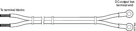
The DC interconnect cables (see Figure A-1) supplied with your AC-input power shelf attach to bus terminal studs in the AC-input power shelf using ring-lug connectors; the cables then connect to the DC terminal blocks in each PEMF.
Figure A-1 DC Interconnect Cables
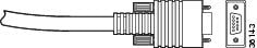
The monitor cable (see Figure A-2) has a proprietary connector on the AC-input power shelf end and a DB-9 connector on the server end that connects to the server PEMF. Figure A-2 shows the monitor cable connectors and receptacles. The pinout of the monitor cable varies slightly between the standard and enhanced AC power shelves.
Figure A-2 Monitor Cable
Table A-13 describes the cable pinout used with the AC power shelf.
Table A-13 AC Power Shelf Monitor Cable Pinout
DB-9 Pin
|
Signal Description
|
1
|
AC power failure warning signal
|
2
|
AC power shelf overtemperature signal
|
3
|
AC power shelf fault signal
|
4
|
Ground
|
6
|
Ground
|
7
|
Ground
|
8
|
Ground
|
9
|
AC power shelf missing module
|

 Feedback