Feedback
Table Of Contents
Quad T1/PRI and E1/PRI Cards (Without Serial Support)
Quad T1/PRI and E1/PRI Cards (With Serial Support)
Troubleshooting Network Interfaces
Troubleshooting
This appendix describes how to troubleshoot the access server by referring to the LEDs on the chassis and cards and using the Bantam jacks. The appendix contains the following sections:
•
LEDs
•
LEDs
Note
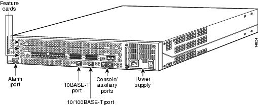
Figure A-1 Access Server Rear Panel LEDs
Figure A-2 Quad T1/PRI Card (Without Serial Support) LEDs
Figure A-3 Quad E1/PRI Card (Without Serial Support) LEDs
Figure A-4 Quad E1/PRI or T1/PRI (With Serial Support) LEDs
Figure A-5 Octal T1/PRI and E1/PRI Card LEDs
Figure A-6 MICA Card LEDs
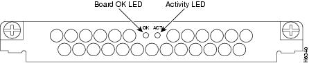
Figure A-7 12-Port V.34 Modem Card LEDs
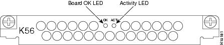
Figure A-8 12-Port 56K Modem Card LEDs
Figure A-9 VoIP Feature Card LEDs
The LEDs indicate the current operating condition of the access server. You can observe the LEDs, note any fault condition that the product is encountering, and then contact your system administrator or a customer service representative (see "Cisco Connection Online" in the "Preface"), if necessary. Refer to for a description of the LEDs.
Table A-1 LEDs
Access server chassis
Alarm
On
An alarm error is detected.
Ethernet
Flickering
Off
The Ethernet LAN connection is transmitting and receiving data normally.
The Ethernet LAN connection is not transmitting or receiving data. Check the Ethernet cable connections.
System Status (Located to right of Console/Auxiliary ports)
Off
On
Blinking
Power is off or system has not booted.
System is operating normally.
A memory failure occurred.
Quad T1/PRI card
Activity (ACT)
Flickering
The CSU/DSU in the card is communicating with a remote CSU/DSU.
Board OK (OK)
On
The T1/PRI card has passed initial power-up diagnostics tests and is operating normally.
Loopback (LB)
On
A local or remote loopback diagnostic test is running on the associated T1 port.
Monitor (MON)
On
Using the MON SEL switch, the signals to/from the associated T1 port switched to the Bantam jacks for test purposes. Only one port can be selected for monitoring. Normally, none of the MON LEDs is on.
Remote Alarm (RA)
On
An alarm is received on the associated T1 port, indicating loss of signal (LOS) or loss of multiframe alignment (OOF) at the remote node.
Local Alarm (LA)
On
The associated T1 port detected loss of signal (LOS) or loss of multiframe alignment (OOF) errors on the local node.
Quad E1/PRI card
Activity (ACT)
Flickering
The CSU/DSU in the card is communicating with a remote CSU/DSU.
Board OK (OK)
On
The E1/PRI card passed initial power-up diagnostics tests and is operating normally.
Loopback (LB)
On
A local or remote loopback diagnostic test is running on the associated E1 port.
Impedance (120)
On
Port is configured for 120-ohm line termination.
If Off, port is configured for 75-ohm line termination.Remote Alarm (RA)
On
An alarm is received on the associated E1 port, indicating loss of signal (LOS) or loss of multiframe alignment (OOF) at the remote node.
Local Alarm (LA)
On
The associated E1 port detected loss of signal (LOS) or loss of multiframe alignment (OOF) errors on the local node.
Octal E1/PRI and T1/PRI cards
Activity (ACT)
Flickering
The CSU/DSU in the card is communicating with a remote CSU/DSU.
Board OK (OK)
On
The card passed initial power up diagnostics tests and is operating normally.
Loopback (LB)
On
A local or remote loopback diagnostic test is running on the selected port.
Local Alarm (LA)
On
The selected port detected loss of signal (LOS) or loss of multiframe alignment (OOF) errors on the local node.
Remote Alarm (RA)
On
An alarm is received on the selected port, indicating loss of signal (LOS) or loss of multiframe alignment (OOF) at the remote node.
Switch Select (left LED under a port)
Green
Port is selected (by pressing the push button switch).
Alarm (right LED under a port)
Yellow
Indicates alarm condition at the port. Check the LB, LA, and RA LEDs to find out the type of alarm.
T0, T1, T2, and T3
Green
Indicates activity at the corresponding serial port.
MICA card
Activity (ACT)
Flickering
There is modem call activity on the MICA modem module cards.
Off
There is no modem call activity on the MICA modem module cards.
Board OK (OK)
One flash
The card is powering up.
On
The card passed initial power-up diagnostics tests and is operating normally.
Off
A fault condition occurred.
12-port modules1
Activity (ACT)
Flickering
There is transmit activity on one or more modems on this module.
Board OK (OK)
On
The card passed the initial power-ON diagnostic tests and is operating normally.
Off
A fault condition is present on the card.
VoIP feature card
Activity (ACT)2
Flickering
There is call activity on the DSP modules.
Off
There is no call activity on the DSP modules.
Board OK (OK)
One flash
The VoIP feature card is powering up.
On
The VoIP feature card passed initial power-up diagnostics tests and is operating normally.
Off
A fault condition occurred.
1 The 6-port modem module does not include LEDs.
2 The individual DSP modules do not include LEDs.
Bantam Jacks
Quad T1/PRI and E1/PRI Cards (Without Serial Support)
If a T1 controller does not go up, or there is a large number of errors associated with a particular controller, you might be able to determine whether the problem is in the quad T1/PRI card or in an external T1 line by using the Bantam jacks. A rotary switch at the front of the T1/PRI card selects which of the four T1 lines are to be monitored/inspected. The LED labeled MON indicates which T1 line is connected to the Bantam jacks.
External test equipment, such as a bit error rate tester, can be used to inject data into the TX IN jack and receive data from the RX OUT jack with the remote location in loopback. This would be an invasive test that would disrupt connections on that T1 port. Another example is to use passive monitoring equipment that can listen on the TX MON and RX MON jacks during regular operation to detect T1 errors.
Connecting test equipment to the following Bantam jacks provides various functions:
•
•
•
•
•
•
Quad T1/PRI and E1/PRI Cards (With Serial Support)
If a T1 or E1 controller does not go up, or there is a large number of errors associated with a particular controller, you could determine whether the problem is in the octal card or in an external line by using the Bantam jacks. A push button switch at the back of the octal card selects one of the eight T1 or E1 lines to be monitored or inspected. The LED labeled MON indicates which E1 or T1 line is connected to the Bantam jacks.
You can only use passive monitoring equipment that can listen on the TX MON and RX MON jacks during regular operation to detect errors.
Connecting test equipment to the following Bantam jacks provides these functions:
•
•
Octal T1/PRI and E1/PRI Cards
If a T1 or E1 controller does not go up, or there is a large number of errors associated with a particular controller, you could determine whether the problem is in the octal card or in an external line by using the Bantam jacks. A push button switch at the back of the octal card selects one of the eight T1 or E1 lines are to be monitored or inspected. The LED labeled MON indicates which E1 or T1 line is connected to the Bantam jacks.
You can only use passive monitoring equipment that can listen on the TX MON and RX MON jacks during regular operation to detect errors.
Connecting test equipment to the following Bantam jacks provides these functions:
•
•
Troubleshooting Network Interfaces
For information about isolating problems with the network connections to your access server, refer to the publication Troubleshooting Internetworking Systems available on the Cisco Documentation CD-ROM that shipped with the Cisco AS5300. For more information, see the section "Additional Documentation" in the Preface.
Getting Help
For information about technical support, onsite service, and exchange and repair services, refer to the Cisco Information Packet that shipped with the Cisco AS5300 universal access server.