Feedback
Table Of Contents
Maintaining Safety with Electricity
Preventing Electrostatic Discharge Damage
Preparing to Connect to a Network
Setting the Receive Shield Jumpers
Four Serial Interface Connections
Console and Auxiliary Port Considerations
Preparing to Install
This chapter describes the tasks you must perform before you begin to install the access server and includes the following sections:
•
Preparing to Connect to a Network
Safety Recommendations
Any device that uses electricity must be handled carefully; follow these guidelines to ensure general safety:
•
•
•
•
•
•
Warning
Ultimate disposal of this product should be handled according to all national laws and regulations.
Maintaining Safety with Electricity
Warning
Before working on equipment that is connected to power lines, remove jewelry (including rings, necklaces, and watches). Metal objects will heat up when connected to power and ground and can cause serious burns or can weld the metal object to the terminals.
Follow these guidelines when you work on equipment powered by electricity.
•
•
•
•
•
Warning
When installing the unit, the ground connection must always be made first and disconnected last.
•
•
Warning
Read the installation instructions before you connect the system to its power source.
•
•
•
•
•
•
Warning
This product relies on the building's installation for short-circuit (overcurrent) protection. Ensure that a fuse or circuit breaker no larger than 120 VAC, 15A U.S. (240 VAC, 10A international) is used on the phase conductors (all current-carrying conductors).
Preventing Electrostatic Discharge Damage
Electrostatic discharge (ESD) can damage equipment and impair electrical circuitry. ESD damage occurs when electronic components are improperly handled and can result in complete or intermittent failures.
Always follow ESD-prevention procedures when you remove and replace components. Ensure that the chassis is electrically connected to earth ground. Wear an ESD-preventive wrist strap, ensuring that it makes good skin contact. Connect the grounding clip to an unpainted surface of the chassis frame to safely ground unwanted ESD voltages. To guard against ESD damage and shocks, the wrist strap and cord must operate properly. If no wrist strap is available, ground yourself by touching the metal part of the chassis.
CautionFor safety, periodically check the resistance value of the antistatic strap, which should be between 1 and 10 megohm (Mohm).
Preparing to Connect to a Network
When you set up your access server, consider distance limitations and potential electromagnetic interference (EMI) as defined by the Electronic Industries Association (EIA).
Warning
Hazardous network voltages are present in WAN ports regardless of whether power to the router is OFF or ON. To avoid electric shock, use caution when working near WAN ports. When detaching cables, detach the end away from the router first.
Warning
The ISDN connection is regarded as a source of voltage that should be inaccessible to user contact. Do not attempt to tamper with or open any public telephone operator (PTO)-provided equipment or connection hardware. Any hardwired connection (other than by a nonremovable, connect-one-time-only plug) must be made only by PTO staff or suitably trained engineers.
Network Specifications
lists the network specifications you should consider before connecting the T1/PRI card to a network.
Table 2-1
Line rate
1.544 Mbps
Data rates
number x 56 or number x 64 kbps, where number = 1 to 24
Standards
AT&T Pub. 62411, 54016, and 43801
ANSI T1.403
T1/PRI Card Network Specifications
lists the network specifications you should consider before connecting the E1/PRI card to a network.
Table 2-2
Line rate
2.048 Mbps
Data rates
number x 56 or number x 64 kbps, where number = 1 to 31
Standards
G.703
E1/PRI Card Network Specifications
Quad T1/PRI Card
The Quad T1/PRI card includes four RJ-45 ports. Cables are not included with the cards; however, cable specifications and port pinouts are listed in the appendix "."
A 10-position rotary switch allows the user to choose which of the four ports is selected for monitoring through the two sets of Bantam jacks (TXMON, TXIN, TXOUT, and RXMON, RXIN, RXOUT). See the appendix "" for a detailed description of the signals available at each of the Bantam jacks. The LED labeled MON at each port lights to indicate that port has been selected for monitoring. Only one port can be selected at a time. None of the ports is selected when the switch is set to the OFF position and all of the LEDs are off.
Figure 2-1 Quad T1/PRI Card
Quad E1/PRI Card
The Quad E1/PRI WAN card includes four RJ-45 ports for terminating 120-ohm balanced lines or 75-ohm unbalanced lines. Cables are not included with the card; however, cable specifications and port pinouts are listed in the appendix "."
Figure 2-2 Quad E1/PRI Card
Setting the Port Impedance
A 10-position rotary switch (labeled IMP SEL) allows you to choose the number of ports that are terminated as 75-ohm unbalanced lines. The LED labeled 120 at each port indicates the input impedance of that port. If the LED is on, it indicates the impedance of the port is set to 120 ohms. If the LED is off, it indicates the impedance of the port is set to 75 ohms.
The input impedance of each port for various impedance selection switch settings is shown in .
Table 2-3 Impedance Selection Switch Settings
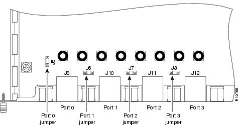
Setting the Receive Shield Jumpers
Jumpers on the Quad E1/PRI card configure the 75-ohm unbalanced ports so the receive shield is connected to ground. You can remove these jumpers to disconnect the receive shield from ground.
Figure 2-3 Receive Shield Jumpers for 75-ohm Unbalanced Ports
Octal T1/PRI or E1/PRI Card
You can install an Octal T1/PRI or E1/PRI card (see ) in any slot of the access server chassis. The board provides 8 RJ-45 T1 or E1 PRI ports and 4 serial interfaces for backhaul WAN support. It also contains Bantam jacks for troubleshooting purposes, which are controlled through the software.
Figure 2-4 Octal T1/PRI or E1/PRI Card
The T1/PRI ports are configured as 100-ohm per port. For the Octal E1/PRI WAN card, the eight ports can be configured as 75- or 120-ohm lines. The factory-set default is 120-ohm. Note that, unlike the Quad E1/PRI card, the Octal E1/PRI card does not include a rotary switch to choose the input impedence for the ports; you change the impedence using a software control register. See the Cisco AS5300 Universal Access Server Software Configuration Guide for details.
Cables are not included with the card. However, cable specifications and port pinouts are listed in the Cisco AS5300 Universal Access Server Module Installation Guide publication.
Four Serial Interface Connections
The four serial interfaces support the following six types of serial interface standards in data terminal equipment (DTE) and data communications equipment (DCE) modes:
•
•
•
•
•
•
MICA and Microcom Cards
The MICA and Microcom cards do not include physical ports to which you connect an external device. The cards connect to the network through the system backplane to a Quad or Octal T1/PRI or E1/PRI card installed in the access server chassis. Data is transmitted or received on T1 or E1 lines connected to the Quad or Octal T1/PRI or E1/PRI card and then routed to the modules on the cards.
6- and 12-Port Modem Modules
The 6- and 12-port modem modules connect to the network through the system backplane of their respective cards installed in the access server chassis. Data is transmitted or received on T1 (or E1) lines connected to the Quad or Octal T1/PRI (or E1/PRI) card, then routed to the modem modules on the cards.
Ethernet Connections
There are two Ethernet ports on the rear panel of the access server: 10BaseT and 10/100BaseT (selectable). Both ports use unshielded twisted-pair (UTP) cable, and the 10/100BaseT port requires Category 5 cable. The maximum segment distance is 328 feet (100 meters). UTP cables look like the cables used for ordinary telephones; however, UTP cables meet certain electrical standards that telephone cables do not. Cables are not included.
Console and Auxiliary Port Considerations
The access server includes an asynchronous serial console and auxiliary port. The console and auxiliary ports provide access to the access server either locally (with a console terminal) or remotely (with a modem). This section discusses important cabling information to consider before connecting a console terminal (an ASCII terminal or PC running terminal emulation software) to the console port or modem to the auxiliary port.
The main difference between the console and auxiliary ports is that the auxiliary port supports hardware (Request To Send [RTS])/Clear To Send [CTS]) flow control and the console port does not. Flow control paces the transmission of data between a sending device and a receiving device. Flow control ensures that the receiving device can absorb the data sent to it before the sending device sends more.
When the buffers on the receiving device are full, a message is sent to the sending device to suspend transmission until the data in the buffers has been processed. Because the auxiliary port supports flow control, it is ideally suited for use with the high-speed transmissions of a modem. Console terminals transmit at slower speeds than modems; therefore, the console port is ideally suited for use with console terminals.
Console Port Connections
The access server includes an EIA/TIA-232 asynchronous serial console port (RJ-45). Depending on the cable and the adapter used, this port will appear as a data terminal equipment (DTE) or data communications equipment (DCE) device at the end of the cable. Your access server arrives with cables and adapters to connect a console terminal (an ASCII terminal or PC running terminal emulation software) to the console port. To connect an ASCII terminal to the console port, use the RJ-45 rollover cable with the female RJ-45-to-DB-25 adapter (labeled TERMINAL).
To connect a PC running terminal emulation software to the console port, use the RJ-45 rollover cable with the female RJ-45-to-DB-9 adapter (labeled TERMINAL). The default parameters for the console port are 9600 baud, 8 data bits, no parity, and 2 stop bits. The console port does not support hardware flow control.
For detailed information about installing a console terminal, see the chapter
"." See appendix "" for cable and port pinouts.Auxiliary Port Connections
The access server includes an EIA/TIA-232 asynchronous serial auxiliary port (RJ-45) that supports flow control. Depending on the cable and the adapter used, this port will appear as a DTE or DCE device at the end of the cable. Your access server arrives with a cable and an adapter to connect a modem to the auxiliary port. To connect a modem to the auxiliary port, use the RJ-45 rollover cable with the male RJ-45-to-DB-25 adapter (labeled MODEM).
For detailed information about connecting devices to the auxiliary port, see the chapter "." See the appendix "" for cable and port pinouts.
Alarm Port Connections
With the alarm ports connected and configured, IOS polls every one second to detect the failure events that are configureed and turns ON the alarm when it detects any failure event.
Note
Power Supply Considerations
Check the power at your site to ensure that you are receiving "clean" power (free of spikes and noise). Install a power conditioner if necessary.
Warning
The device is designed to work with TN power systems.
The access server AC power supply includes the following features:
•
•
Warning